patent · US4716258
Stamped concentrators supporting photovoltaic assemblies
29 December 1987
Page 1 — bibliographic record
United States Patent (19) 11 Patent Number: 4,716,258 Murtha (45) Date of Patent: Dec. 29, 1987 (54. STAMPED CONCENTRATORS 4,519,384 5/1985 Murtha ................................ 126/438 SUPPORTING PHOTOVOLTAC 4,604,494 8/1986 Shepard, Jr. ... ... 136/246 ASSEMBLES 4,683,348 7/1987 Pidgeon et al. ..................... 136/246 76 Inventor: R. Michael Murtha, 1010 Janetwood FOREIGN PATENT DOCUMENTS Dr., Oxnard, Calif. 93.030 330730 10/1935 Italy .................................... 350/613 (21) Appl. No.: 6,373 OTHER PUBLICATIONS 22 Filed: Jan. 23, 1987 Article, Fred Barden, "New Solar Concentrator Dish 51) Int. Cl. ............................................... HO2N 6/00 Taylored for Industrial Use', 8-1981, p. 23, Solar Age 52 U.S. C. .................................... 136/246; 98/121.1 Magazine.
58) Field of Search ......................................... 136/246 Primary Examiner-Aaron Weisstuch 56) References Cited (57) ABSTRACT
1,951,404 3/1934 Goddard ............................. 126/438 concentrate solar energy. In its simplest form the mod 2,144,528 1/1939 Ewald ...... ... 98/12.1 ule is a louvered sheet material platform that is mounted 2,145,073 1/1939 Drake. ... 98/121.1 with a photovoltaic cell assembly. The one-piece unit is 2,366,224 1/1945 Warp. ... 98/121.1 a mass-producible stamping of ribbed monocoque con 2,945,417 7/1960 Caryl ... ... 126/451 struction. Light reflective louvers of the stamping are 3,403,615 10/1968 Dayus ...... ... 98/121.
3,861,379 1/1975 Anderson. ... 126/425 interconnected by a common-border-area grillage that 4,016,861 4/1977 Taylor. ... 126/436 maintains the louverwork position and inclination. The 4,159,710 7/1979 Prast. ... 126/425 louvers can be patterned in novel configurations to 4,173,213 11/1979 Kelly ................................... 126/425 improve the electrical output of solar cells and increase 4,228,789 10/1980 Kay ..................................... 126/439 their service lifetime. The lightweight stamping elimi 4,234,354 11/1980 Lidorenko et al. ................. 136/246 nates the complexity and assembly time associated with 4,249,514 2/1981 Jones ................................... 26/438 4,281,640 8/1981 Wells ................................... 126/438 the mirror strips of prior art slatted concentrators. 4,296,731 10/1981 Cluff.................................... 126/424 4,463,749 8/1984 Sobczak et al. ..................... 126/45 4 Claims, 11 Drawing Figures
Page 2
Drawing sheet — no readable text.
Page 3
Drawing sheet — no readable text.
Page 4
Drawing sheet — no readable text.
Page 5
2,366,224 and 3,403,615, these louvered and ribbed
STAMPED CONCENTRATORS SUPPORTING stampings are very inexpensive to mass-produce. PHOTOVOLTAIC ASSEMBLIES It is prudent to incorporate louvered sheet material and slatted solar concentrators as this combination of
BACKGROUND OF THE INVENTION 5 art produces an increased electrical efficiency and a This invention relates to solar energy collectors that lighter module that requires far fewer parts than had heretofore been used or thought necessary. Highly ad track the sun throughout the year. More particularly, vanced modules are presented hereupon. the present invention is concerned with concentrator type collectors that use mirror strips to reflect solar 10 SUMMARY OF THE INVENTION radiation to a focal Zone.
It is now well established that the cost of solar elec All of the modules of the present invention are to be mounted tricity (photovoltaics) can be greatly reduced when an day and year. on heliostats to track the sun throughout the inexpensive optical material is used to concentrate a nected and designed The modules will be electrically intercon large area of sunlight upon the small area of a solar cell. 15 curret. to deliver a specified voltage and In this manner a single photovoltaic cell will generate One-piece, louvered and ribbed, sheet material stamp the same amount of direct current electricity as would ings of monocoque construction are the basis for this many expensive cells.
Presently, parabolic reflectors and Fresnel refractors are feasibleMany invention. novel and well known module shapes are used to concentrate sunlight on cells. Though effec 20 The reflective the using louvered sheet material.
louvers of each module are angled tive, they are about three times too expensive to be during stamping to bring sunlight to a convergence. cost-competitive with conventional power plants. The louvers are connected and held in place by a unify Another type of concentrator is the "slatted' mirror. ing common-border-area that can be formed as a rib. These reflectors, as shown in U.S. Pats. Nos. 1,951,404 These border area ribs make the module rigid by distrib and 2,945,417 use narrow mirror strips, or slats, to per 25 uting the weight of the structure evenly. form work. The focal zone that these reflective slats In accordance with the present invention a common produce is distinctly advantageous to concentrator pho border-area, or rib therein, supports the photovoltaic tovoltaics. In operation, to bring sunlight to conver cell assembly in a fixed aligned position with the lou gence, the slats are set at progressively different angles vers. The louvers reflect and concentrate sunlight onto in a framework. The slats reflect many rectangular 30 the photovoltaic cell, thereby maximizing its electrical paths of light that combine, one on top of the other, output.
upon the rectangular face of the solar cell. This Heat sink type louvers, formed of the same sheet "stacked' type focal zone uniformly illuminates the material, can be used in relationship with the photovol whole cell face which results in a superior electrical taic cell to further improve the efficiency of the module. conversion efficiency. Furthermore, the evenly distrib 35 All prior art concentrator modules are made up of uted character of concentrated sunlight insures that no three separate components: first, the optical element, extreme temperature excursions occur upon the cell. second, the structural housing, and third, the photovol This prolongs the service life of expensive solar cells taic cell assembly. The primary object of this invention and their solder joints thus increasing module durability 40 is to combine these components together in a simple and and reliability. inexpensive stamping that is dedicated to the task of However, these unique advantages cannot overcome concentrating light for photovoltaics.
the high material cost and labor content involved with Another important object is to generate new reflect prior art slatted modules. Their parts are very compli ing geometries and focal zones by using novel louver cated to produce and awkward to assemble. For exam 45 work patterns that are available only on one-piece lou ple, each slat must be manufactured to include a fastener vered stampings.
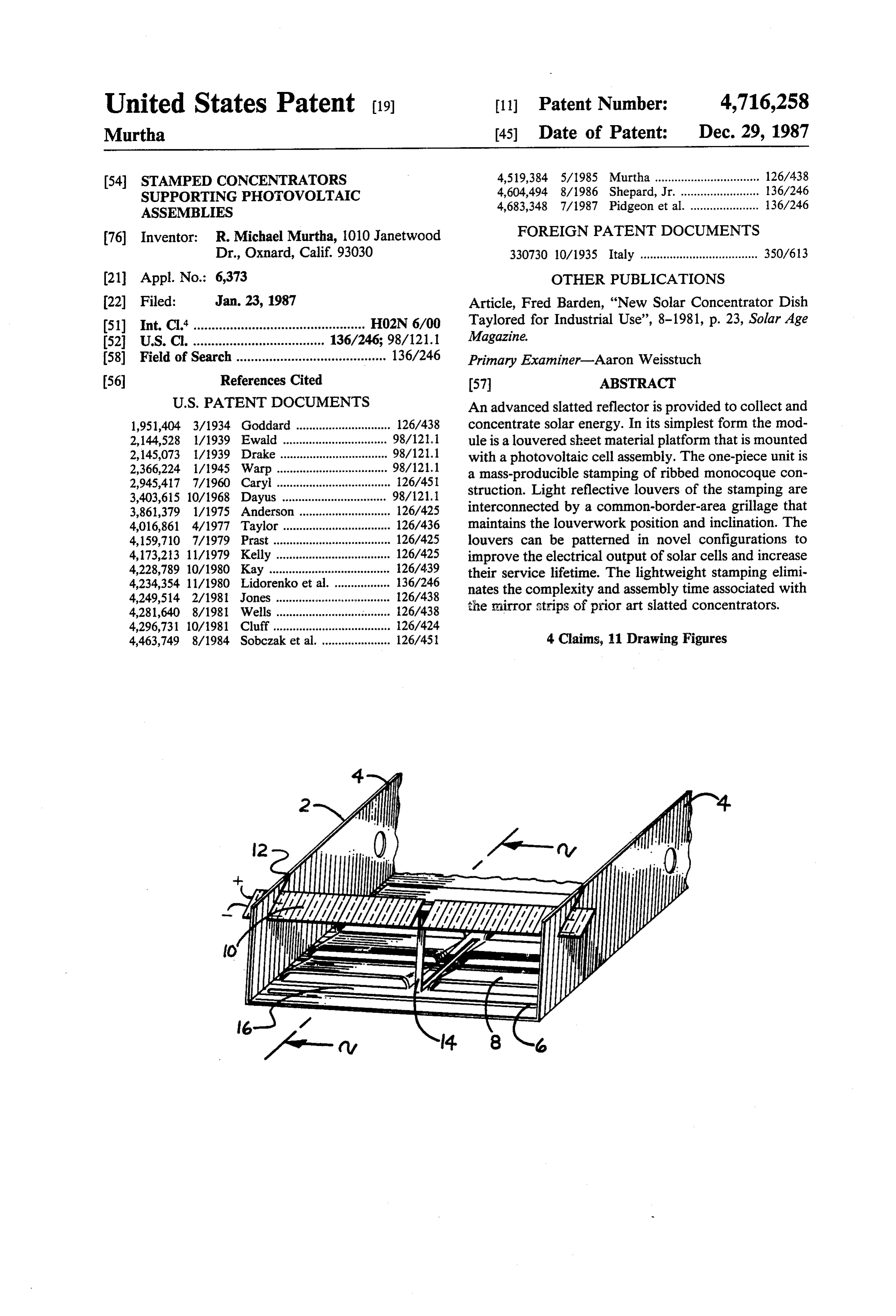
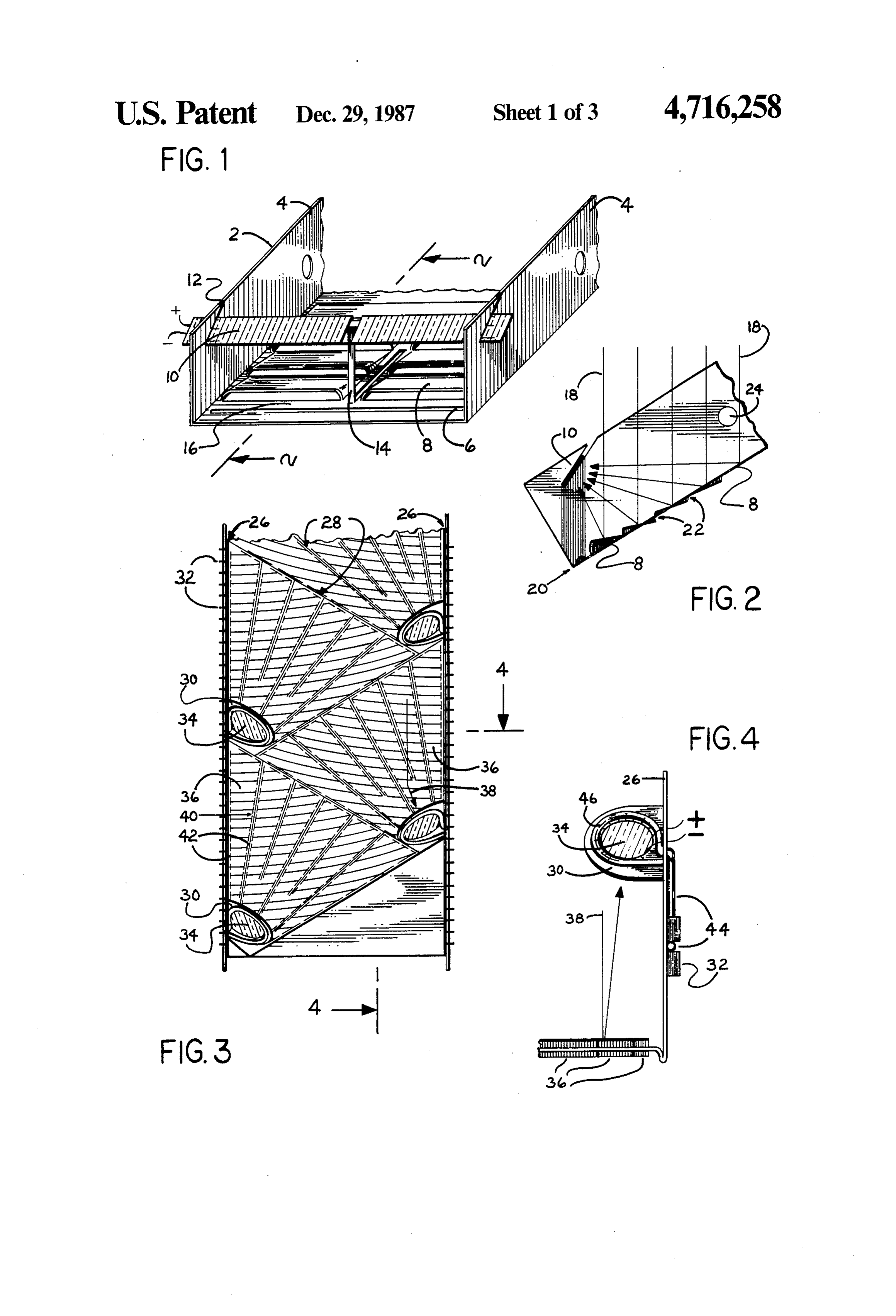
at both ends. Then both ends of each slat must be in Other objects and advantages will become apparent serted into precisely drilled holes in an expensive frame. from the following detailed description when read in Mounted on a fixture and using ray tracing techniques, connection with the accompanying drawings. each slat must be inclined in a manner that assures accu SO rate reflection geometry. Then each of the slats' fasten BRIEF DESCRIPTION OF THE DRAWINGS ers must be carefully tightened without changing the FIG. 1 is a perspective view of the first embodiment inclinations. The result is a delicate and complex device of the invention, the "line focus flat-bottom channel' that has highly desirable optical characteristics. In view module.
of their potential impact as photovoltaic concentrators a 55 FIG. 2 is a portional cross section view taken along real need exists to radically improve the cost-effective lines 2-2 of FIG. 1.
ness of manufacturing slatted reflectors. FIG. 3 is a plan view of the second embodiment, the In U.S. Pat. No. 4,519,384 by the present inventor, "spot focus flat-bottom channel' module. there is shown an enclosed slatted mirror that begins to FIG. 4 is a portional end view taken along lines 4-4 eliminate the multitude of parts associated with the of FIG, 3.
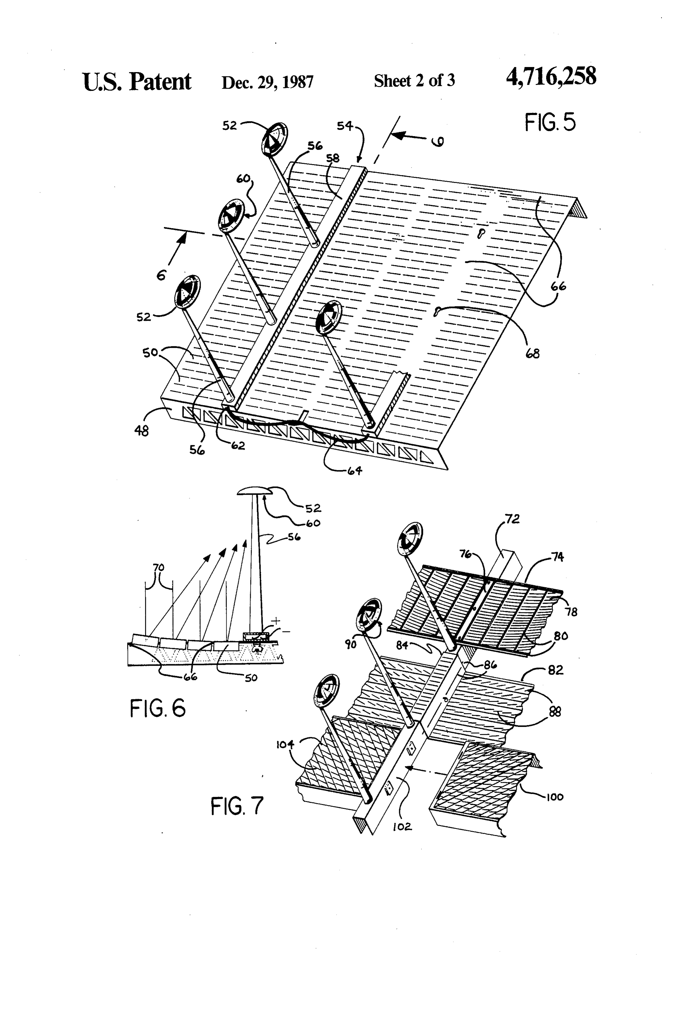
prior art. In that patent I show, but do not claim, one FIG. 5 is a perspective view of the third embodiment, piece louvered sheet material as the optical element. the "platform' type module.
Mounted in a framework, this panel uses stamped lou FIG. 6 is a portional end view taken along lines 6-6 vers to concentrate sunlight rather than individual mir of FIG. 5 showing versatility of stamped louverwork. ror slats of the prior art. Louvered sheet material was 65 FIG. 7 is a representational view of three more "plat developed for heating and ventilation purposes as a form' type modules.
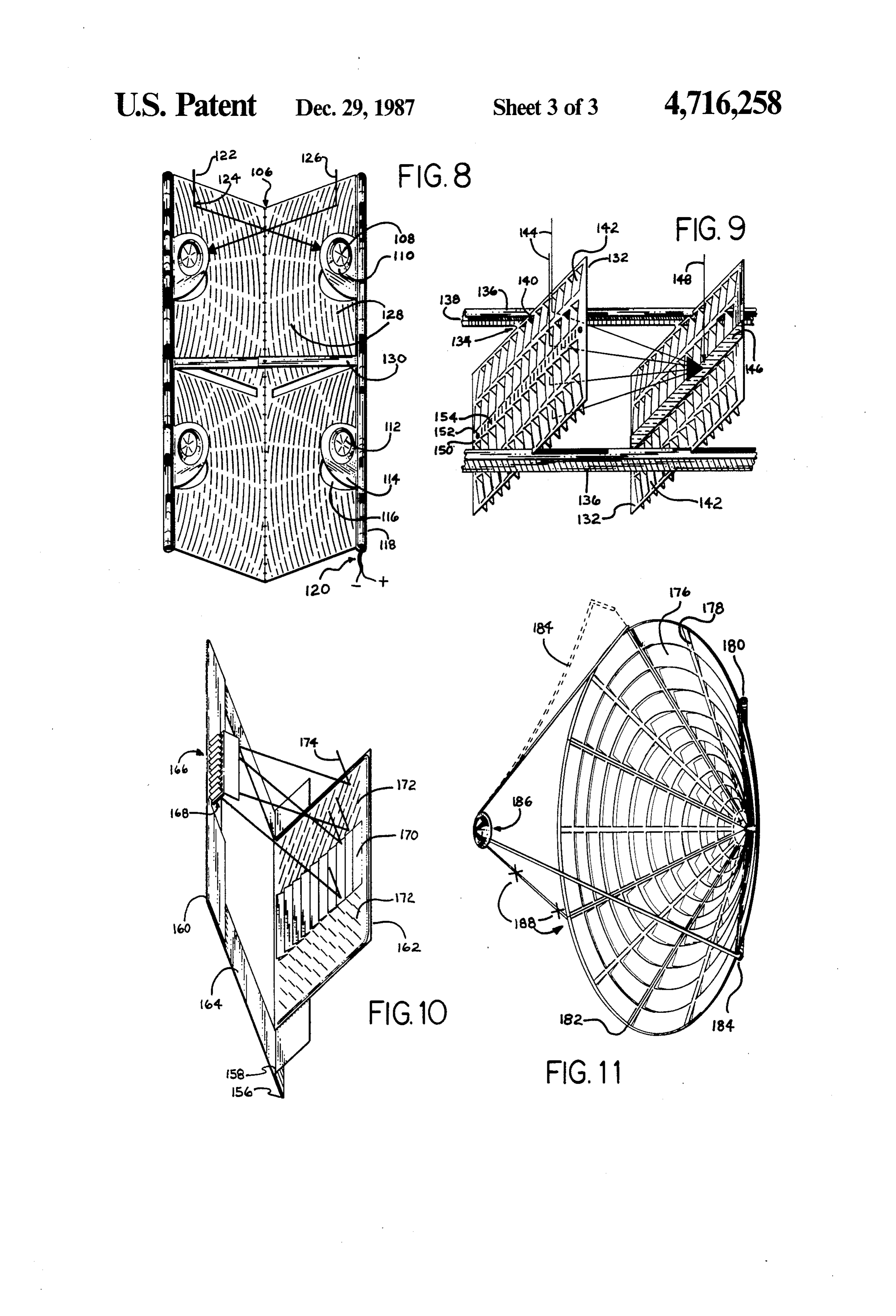
simple, yet sturdy, grill that can be found in most homes FIG. 8 is a perspective view of the fourth embodi and offices today. As embodied in U.S. Pats. Nos. ment, the "V" shaped module.
Page 6
FIG. 9 is a perspective view of the fifth embodiment, FIG. 4 is a partial elevation view taken along lines the "tray-like' module. 4-4 of FIG. 3. Receptacle tabs 30 are punched with a FIG. 10 is a perspective view of the sixth embodi notched hole during stamping to where the photovol ment, the "foldout' module. taic cell assembly 34 is mounted by pressing into place. FIG. 11 is a perspective view of the seventh embodi- 5 The solar cell assembly 34 is an environmentally-sealed ment, the "shallow cone' module. package similar in construction to an automobile head The figures show singular modules that can be either light. The cell assembly contains the photovoltaic cell, propagated in any axis through geometric scaling, or, secondary reflector, diode and leads. Heat sink louvers linked together to form arrays. 32 and tubing 44 mounted therein are provided on the O ribs 26. In practice a fluid runs through the tubing 44
DESCRIPTION OF THE PREFERRED actively cooling the cells by conduction at 46. Heat sink EMBODIMENTS louvers 32, in turn, absorb the heat from the tubing and This invention is amenable to innumerable modifica radiate it through natural convection to the surrounding tions and alternative constructions. Therefore, only air thereby optimizing the module efficiency. Light preferred embodiments are referred to in the descrip path, as represented by ray 38, is directed toward its tab tion, shown in the drawings, and set forth in the claims. 30 by the angled louver 36. The metal sheet is approxi Turning now to FIG. 1, there is shown a module mately fifteen-thousandths of an inch thick. portion in which a solid blank sheet of reflective alumi It is to be understood that all of the sheet material num 2 has been stamped or formed into the shape of a 20 stampings of the present invention are made from flat-bottom channel. Parallel ribs 4 impart a structural blanks that have been prepared in one or more ways rigidity in the longitudinal axis of the module, while before the stamping/pressing operation occures. For bead 6 and hooded-slot louvers 8 impart rigidity in the instance, the sheet stock must be of a thickness, hard transverse axis. The module must be a stiff monocoque ances ness, and ductility that is appropriate for bend allow construction to insure that the louver reflections are required of monocoque construction. The sheet 25 must be able to withstand a slight drawing operation in kept accurate. In this instance the module is a line con critical areas such as at the louver ends and bead areas centrator wherein the long linear louvers reflect narrow as paths of light upon the cell assembly. The linear photo is towell as at the folds of the ribs and flanges. The sheet have a highly reflective finish and may consist of voltaic cell assembly 10, including the cell string, is aluminum, aluminized acrylic mirror or stainless steel. supported by the ribs 4. Cell assembly 10 is oriented on 30 Inexpensive dies may be used during proof-of-con the module by receptacle slots 12 formed of the ribs. cept prototyping of the modules. The final "hard' dies The cell assembly is light and relatively rigid, but if the required distance between the ribs is very wide then a tap type and other featuresthe to stamp sheet with louvers, tabs, ribs, slots would include a male and female set rib 14 would be required to also support the assembly. or a punch used in combination with a die plate. The The tab type rib 14 is formed of the common-border sheet is fed between the two dies. During the moment of area 16 during the stamping process. stamping the louvers are formed by a lancing or slitting FIG. 2 is a cross section view taken along line 2-2 of operation
FIG. 1. The flat-bottom line concentrator can be very type louvers of the dies. Hooded-slot, flap type and tab long with, as an example, twenty cell assemblies 10, common-border-areas and their variations in combination with located on the channels' ribs. A plurality of reflective 40 The decisions and operations are used in the present invention. louvers 8 are devoted to each cell assembly. Each lou these precision stampings would involved with producing ver 8 reflects a rectangular path of light, as represented developed sheet material theory andbepractice based upon well by rays 18, directly to the cell assembly 10 because each the sheet metal and plastic industry today, asandexists more
louver is angled differently by a die during the stamping particularly, among persons involved with sheet mate process. In order to maximize usage of the reflecting 45 rial grill and register manufacturing. surfaces the dies are shaped to cause the louvers to vary FIG. 5 is a different preferred embodiment in the their depths in the sheet material plane 20. Open spaces basic shape of a platform with ribs 48. Made of acrylic 22 between the louvers are a pervasive characteristic of plastic mirror, this module is self-supporting, using the stamped modules. During tracking the module is fewer of the expensive branch ribs that normally would tilted off-axis, in relationship to the incoming parallel 50 support a module on a heliostat. FIG. 5 is also made to rays of the sun, to assure that no rays 18 are allowed to track the sun in an off-axis mode at an angle that insures pass between the louvers unreflected. Holes 24 may be that light does not escape through the open spaces be used to attach modules together, or, as an axis point for tween the louvers. The module is a multiple spot focus tracking the sun. concentrator having louvers 50 positioned to reflect FIG. 3 shows a portion of a preferred embodiment 55 light to single cell holders 52. The photovoltaic cell that is similar in appearance and in tracking mode to assembly 54 is composed of a plurality of cell holders 52 FIGS. 1 and 2. However, it discloses a multiple spot mounted on tubes 56 and attached to a base 58. The cell focus module. Ribs 26 and beads 28 make the module holders 52 include a secondary reflector encompassing rigid. Receptacle tabs 30 and heat sink louvers 32 are a self-contained solar cell 60. Electrical leads run from stamped onto the aluminum sheet before the ribs are 60 the cell buss bars through the tube 56, which protects folded up in a separate process. Receptacle tabs 30 hold the wiring from stray focal spots, and into the base 58 to the solar cell 34 at a predetermined angle to efficiently a terminal 62 located at the end of the base. Electrically receive the concentrated sunlight. Louvers 36 are rigid, isolated from the louvered reflector by the base, cell segmented, parabolic sections that are tilted at progres assembly 54 is connected by a cable 64 to adjacent cell sively different angles to bring sunlight as 38 to a con- 65 assemblies. Cell assembly 54 is supported on the module vergence upon the cell assembly 34. Reflective flap by the common-border-area 66. Cell assembly 54 is to louvers 36 are held and positioned by a transition twist be easily unattached from the module by using securing 40 connected to common-border-area 42. means 68 such as a simple slotted hole used in connec
Page 7
tion with a threaded pin and nut, of the base. Stamped as Convex louvers can be used to improve the uniform a truss, rib 48 maximizes lightness and rigidity. illumination of the cell face and its secondary reflector. FIG. 6 shows a section of the platform module taken All of the modules employ reflective louvers to con along lines 6-6 of FIG. 5. It shows how the straight, centrate parallel rays of sunlight. The modules also stay variably inclined louvers of FIG. 5 are positioned to 5 cooler because of the louvers. Louver edges increase bring sunlight 70 to spot convergence at the solar cell surface area whereby heat can be more effectively con 60. The louvers 50 are stamped descending through the vected away from the module. Louvers, and attendant plane of the sheet material. Canted in their positions and open spaces therebetween, make the module porous held by the common-border-area 66, these novel lou which inhances air current flow past the hot solar cells, vers allow the flat sheet to act as a parabolic equivalent. 10 further improving module conversion efficiency. Such In FIG. 7 the cell assembly 72, including tubes, solar porosity allows the module to be very tolerant of wind cell and base, is equivalent to the assembly of FIGS. 5 making large arrays less likely to de-focus or sustain and 6. The upper louvered sheet 74 is situated and at damage during high winds.
tached to the assembly 72 at a common-border-area 76. Although the module is highly reflective and porous, The cell assembly 72 is very light and easily supported 15 in operation it will absorb a small amount of solar heat. by the common-border-area 76 which, in turn, is stabi Heat gain calculations are simplified as the module is lized by the louvers 78 and beads 80. Louvers 78 are one material and one thickness. The louvers, border curved, interrupted, and supported by additional border areas and ribs will absorb heat at different rates due to areas and beads. This is advantageous as multiple sup their various inclinations. It may be necessary to place ports improve beam delivery accuracy. 20 appropriately sized heat sink slots near the ends of the The middle panel 82 is louvered plastic mirror. Lo louvers, or in the immediately adjacent common-bor cated centrally of the sheet is a folded rib member 84 der-area, to eliminate any temperature gradation expan that supports and orients the cell assembly 72. Cradled sion in order to maintain exact louver inclinations. This in the rib, the assembly is also supported by the interac is especially important when a louvered primary reflec tion of friction beads 86 with mating profiles of the cell 25 tor is mounted with photovoltaic cells in a Cassegrain assembly. Tab type louvers 88 are patterned in horizon configuration. In this situation a separate secondary tal parallel rows and progressively tilted in their rows to reflector, possibly louvered sheet material, is used in a reflect light to a solar cell located at 90. two-reflection device to greatly improve the cells beam Louvered sheet 100 is made like a shoe box lid with acceptance angle.
ribs at all four edges. It is pinned to and supports the cell 30 In FIG. 8 there is shown a different preferred em assembly 72 at one edge 102. The tab louvers 104 are bodiment in the basic form of a "V" shaped trough that patterned in diagonal parallel rows, when compared to has been folded lengthwise at perforations 106. This those of the upper panels, showing the versatility of modular stamping is made of thin, highly polished stain louvered sheet material. The louvers are periodically less steel, or the like, and supports a plurality of solar interrupted in their extent and supported by common 35 cells such as 108. This spot concentrator is intended to border-areas. All of the panels of FIG. 7 are made to reflect a twenty sun concentration ratio to each cell. track the sun in an off-axis mode. Each cell 108 is mounted inside a formed cup 110 and The louvers of the present invention are unique and bonded to the metal using a filled silicone adhesive. economically available only through the use of light Cups 110 are secondary reflectors stamped into the weight louvered sheet material. Louver patterns of the 40 same sheet material as that of the primary reflector. present invention would be too complex to assemble if Also called buttons or bosses, the cups redirect light one were to use the heavy individual mirror strips of the that is slightly askew, onto the solar cell face. The cups prior art slatted concentrators. If individual mirror are populated with heat sink type louvers 112 that pas strips were used to duplicate these louver patterns the sively ventilate heat or otherwise, air-cool the solar cell. resultant slatted module would be hand made, involving 45 The cell, cup and heat sink louvers are included upon a hundreds of pieces and would be extremely delicate. receptacle tab 114. This tab, which also orients the cell, Whereas louvered sheet material is a single piece, is a feature formed of the samesaid sheet material as the highly reliable mechanical stamping, with a production primary reflector. Cutouts 116 are open spaces left by rate of, possibly, one unit per second, Louvered sheet the tabs during stamping. Narrow ribs 118, or wired material gives the photovoltaic specialist the freedom to 50 edges, run coextensive of the module and are formed to choose virtually any configuration of reflection geome provide a snap-on capability for attachment to a helio tries and concentration ratios. The engineer now has stat. They also function as a protective conduit for the control to produce a specific voltage and current from wiring harness 120 that is fed by the photovoltaic cells. nearly any shape of module that a situation may require. Light ray122 reflects from louver 124 on one side of the All louver patterns of the present invention are main 55 primary reflector to a solar cell on the opposite side of tained upon or within the flat surface of the sheet mate the module. Ray 126 reflects in like manner, across to rial. High concentration ratios and uniform illumination the other side. This "crossed' type geometry is benefi profiles are produced by periodically segmented lou cial to many configurations of louvered sheet material vers eliminating the long, looping, unbalanced, and as it replaces cell assembly riser tubes with sturdy inte unsupported slats of the prior art. gral sheet material fixtures (receptacle tabs). Common The louvers can be stamped with straight or curved border-areas 128 lend rigidity and separate the rows of edges in the longitudinal axis. In the short axis they are curved, segmented louvers 124. Stiffeners 130, formed preferrably planar and with approximate the width of of the sheet, are joined at the center and help maintain the solar cell. Specialized louvers, where the short axis the modular trough shape.
is compound planar (creased) or parabolic, are easy to 65 Sheet material integral rib structures are used stamp and increase the concentration ratio. The short throughout the present invention. These structures in axis can also be stamped convex to slightly disperse the clude sheet material features such as: ribs, beads, bends, light in which case the louvers can be made smaller. flanges, channels and bosses. In some cases special
Page 8
ribbed louvers and common-border-areas are equivalent "foldout' module. As with all the modules, a blank of to rib type structures. Either folded in or stamped, these reflective sheet material is placed between a set of dies features serve to stiffen and add to the buckling resis in a press. The flat stock is then struck or stamped by tance of the sheet material. The stiffening properties of the dies with louvers, beads, perforations, and long slits. ribs make possible a unit-body or monocoque structure 5 After removal from the press, the stamping is then ma which allows the unit to become a weight bearing plat chine, or manually, folded along perforations at 156, 158 form. The weight bearing platform of the present inven and 160 resulting in strongback ribs, support ribs, and tion is then loaded at specific points along its rib struc stiffening ribs, respectively. The louvered panel 162 is ture(s) with a lightweight photovoltaic cell assembly, also folded out and held in position by support rib 158. making the unit a complete concentrator module. Gen- 10 The folding out of the panel leaves a standing rectangu erally, these rib structures are very strong and require lar rib member 164. Housing 166 formed of samesaid no handling as they are an integral part of the louvered sheet material is located centrally of the upper quarter module and do not need to be attached by fasteners. Not of the standing rib member. Housing 166 is a secondary only are rib structures used to replace module frame reflector that also attaches and orients the short photo works, they are also intended to eliminate, reduce, or, at 15 voltaic cell assembly 168. Heat sink louvers are located least, limit the number of expensive separate branch in the upper surface of the housing. The panel 162 con members associated with the torque tube of a heliostat. tains
Both single and double fold ribs can be used to dampen focus louverwork that is that produces a unique "short line' economically available only through the use the effects of vibration and thermal cycling.
It should be understood that the photovoltaic cell 20 of stamped sheet material. Short linear louvers 170, located centrally of the panel, are the same length as assembly will be the smallest but most expensive part of cell assembly 168. They are inclined at progressively the concentrator module. In the event that the louvered reflector or the cell assembly becomes damaged and upon the angles different and reflect rectangular paths of sunlight closely associated photovoltaic cells of the cell needs to be replaced it should be a simple operation to assembly 168. Tilted tab louvers 172, located on both disassociate them. Therefore, during the stamping oper- 25 ation, features such as shaped holes, slots, notches, and sides of the linear louvers 170, boost the concentration friction channels are to be included in the rib structure ratio by reflecting light diagonally 174 onto the cell areas that enhance the alignment and quick-connection assembly 168. The additional concentrated radiation capabilities of the photovoltaic cell assembly. In like would, for example, nearly triple the electrical output of manner, damaged adjacent modules are to be stamped 30 the cell string. Rib member 164 of the module is to be with quick-connection features to facilitate their re pointed directly toward the sun during operation. placement. FIG. 11 is a different preferred embodiment in the FIG. 9 is a portion of a different preferred embodi basic shape of a shallow cone having flat sides in cross ment in which reflective sheet aluminum is stamped section. The flat sided cone lacks the expensive para bolic framework associated with the similarly appearing with large louvers that contain smaller louvers and 35 parabolic photovoltaic cell assemblies. This "tray-like' module is dish. The module is prepared by first locating formed of the single piece of sheet material. Large the center of a piece of circular reflective sheet material frame louvers 132 are unified and held in position by a and then cutting out a "pie section' of about thirty common-border-area frame at transition area 134. Bor degrees. The sheet is then stamped in a flat position with der are frame 136 is flanged 138 and notched 140 during 40 louvers 176 and common-border-areas 178 that contain stamping to index and retain the large planar louvers stiffener/friction channels 180. The edges of the cut out 132 in proper position. The large louvers are populated section are brought together at 182 and secured forming with curved and segmented reflecting louvers 142 that the cone. Friction channels 180 engage and support are inclined, in this case, at the same angle. They reflect snap-in struts 184 of the cell assembly. The cell assem light rays 144 through and behind the plane of the large 45 bly positions the solar cell 186 directly in front of the frame louvers 132 to convergence upon linear photo module. The module is steered directly toward the sun voltaic cell assembly 146 located on an adjacent frame and can be designed to produce a fifty to five-hundred louver. Adjacent frame louvers may be brought closer sun geometric concentration ratio. Curved and periodi together in order to use all available sunlight, with cally interrupted, the variously inclined louvers 176 "pinch beads' formed of the common-border-area 50 redirect incoming sunlight to the cell face. Multiple frame 136. This module can be mounted in a tiered focal zones 188 indicate when focal spots may be system where two modules are positioned one above trained if so desired, by reconfiguring the louvers. A the other with the large louvers of the lower module square (pyramidal) version of this module is available located below and between the large louvers of the due to the versatility of the louvers.
upper module. A concentration often to twenty suns is 55 The invention has been described in detail with par anticipated for this module that is to be steered directly ticular reference to the preferred embodiments thereof, toward the sun in at least one axis. An additional sun but it should be understood that reasonable variations represented by ray 148, shines directly upon the cell and modifications are possible without departing from assemblies. Common-border-area seat 150 provides a the spirit and scope of the invention.
sturdy grillage that supports a cell assembly, as 146, 60 What I claim is:
along its length. This seat area 150 is perforated 152 to 1. A radiant energy concentrating collector compris provide a snap-in capability for the cell assembly. It is 1ng:
also populated with heat sink louvers 154 that are dis reflective sheet material formed as a module and tributed along its length. Photovoltaic cell assembly 146 having stamped louvers therein with open spaces is an encapsulated cell string composed of ARCO Cz or 65 therebetween and connected by common-border Solarex poly silicon cells, for example. areas, said common-border-areas including rib FIG. 10 shows a different preferred embodiment means, said rib means supporting a photovoltaic constructed of one-piece louvered sheet material: a cell assembly, the louvers being positioned to re
Page 9
flect sunlight falling on the module to said photo- flector that further supports and concentrates light 2. . Yeti R ity d in claim 1 wherei le OCleaS Cleted in Call I Were:
upon said photovoltaic cell assembly.
4. The module as defined in claim 1 wherein:
the sheet material is also formed with heat sink lou vers that further support and cool said photovo. 5 saidformed taic cell assembly.
common-border-area or rib means therein is to provide a securing means to further 3. The module as defined in claim 1 wherein: support said photovoltaic cell assembly. the sheet material is also formed as a secondary re- k k is is sk
Provenance
- Collection
- Cited prior art
- Original PDF
- patentimages.storage.googleapis.com →
- Filed
- 1987-01-23
- Pages
- 9
- Method
- pdftotext (the PDF's own text layer) + pdftoppm 300dpi page scans
- Source
- Google Patents bibliographic record
- Granted
- 1987-12-29
- Inventors
- R. Michael Murtha
- Transcribed from
- patentimages.storage.googleapis.com →