patent · US4513728
Air/fuel induction system for spark ignition internal combustion engines, and electromagnetic valves
30 April 1985
Page 1 — bibliographic record
United States Patent (19) 11 Patent Number: 4,513,728 Ullman et al. 45 Date of Patent: Apr. 30, 1985 54 AIR/FUEL INDUCTION SYSTEM FOR 2948449 4/1981 Fed. Rep. of Germany . SPARK IGNITION INTERNAL 2365703 9/1977 France
COMBUSTION ENGINES, AND 2456856 l/1981 France ................................ 123/527 ELECTROMAGNETIC VALVES 542627 1/1942 United Kingdom .
75) Inventors: Thomas J. Ullman, Cranfield; Colin 1093573 12/1967 United Kingdom . F. Shadbolt, Leighton Buzzard; Brian 2014336 8/1979 United Kingdom .
C. Pagdin; David J. Marriage, both of 1552937 9/1979 United Kingdom .
Dunstable; Peter J. Clarke, Leighton 1565706 4/1980 United Kingdom .
Buzzard; Ian J. Sheppard, St. Albans, 1569655 6/1980 United Kingdom.
all of England Primary Examiner-E. Rollins Cross 73) Assignee: Solex (U.K.) Limited, Middlesex, Attorney, Agent, or Firm-Parkhurst & Oliff England 57 ABSTRACT 21 Appl. No.: 449,786 A motor vehicle fuel system operable selectively to 22) Filed: Dec. 14, 1982 supply metered quantities of petrol or LPG in its gase 30 Foreign Application Priority Data ous state to a carburetter induction passage. The LPG system includes a single stage pressure regulator and an
Jan. 15, 1982 GB United Kingdom ................. 8201 104 injection valve which may be a digital or an analogue valve. The regulator operates to vary the pressure of 51) Int. Cl. ............................................. F02M 13/06 gaseous LPG with variations in engine loading by refer 52 U.S. C. .................................... 123/527; 123/478; ring that pressure across a single diaphragm to the pres 123/480; 261/69 R; 251/61.5 sure established in the induction passage downstream of 58) Field of Search ............... 123/527, 557, 480, 472, the throttle valve by operation of the engine, while 123/478; 261/69 A, 69 R; 251/61.5; 137/DIG. maintaining that regulated gas pressure above that sub
sisting in the induction passage upstream of the throttle (56) References Cited valve. An electronic control system, which may be an
incorporating a microprocessor having a data store 2,357,947 9/1944 Gerson ................................ 123/527 matrix, responds to certain engine operating conditions 2,696,714 12/1954 Hughes . and controls operation of the injection valve whereby 2,821,843 2/1958 Mengelkamp et al. ............. 123/527 the latter injects metered quantities of gaseous LPG for 3,543,784 12/1970 Smith ...................................... 137/8 3,960,126 6/1976 Shinoda ............................... 123/527 presentation to the induction passage upstream of the 4,020,810 5/1977 Baverstock ......................... 123/527 throttle valve in accordance with the requirements of 4,109,616 8/1978 Zechnal et al. .................... 123/478 the engine. If a digital injection valve is used, provision 4,141,326 2/1979 Wolber ........... 123/DIG. 12 is preferably made for smoothing the pulsed output of 4,335,697 6/1982 McLean .............................. 123/527 that valve before it is presented to the induction pas Sage.
FOREIGN PATENT DOCUMENTS
2131804 12/1972 Fed. Rep. of Germany . 17 Claims, 5 Drawing Figures
Page 2
Drawing sheet — no readable text.
Page 3
Drawing sheet — no readable text.
Page 4
Drawing sheet — no readable text.
Page 5
Drawing sheet — no readable text.
Page 6
on fuel enrichment. Also the low temperature operation
AIR/FUEL INDUCTION SYSTEM FOR SPARK of the equipment is often unsatisfactory. IGNITION INTERNAL COMBUSTION ENGINES, The equipment is critically dependent upon the mixer AND ELECTROMAGNETIC VALVES units but it has proved difficult to design mixer units which are sufficiently flexible in their application for
BACKGROUND AND SUMMARY OF THE them to be properly matched with the engine's require INVENTION ments. Furthermore the mixer units of the LPG conver This invention relates to air/fuel induction systems siontheequipment can significantly influence the operation for spark ignition internal combustion engines. Such 10 ofThe basic petrol fuel system in an undesirable manner. fact that the delivery stage of the part of the systems comprise an air/fuel induction passage with a driver-operable throttle valve therein, and a fuel system equipment regulator that includes the vaporizer and pressure operates at a low, near atmospheric pressure by which gaseous fuel is presented to a location in the leads to a requirement for large "active' areas but the induction passage, the gaseous fuel being vaporized resultant design compromise limits accuracy, sensitiv liquefied petroleum gas (LPG), or a natural gas, such as 15 ity, dynamic response and durability methane. This invention also relates to electromagnetic Attempts to minimise these functionalofdeficiencies the equipment.
have valves which are suitable for use in such systems.
Equipment for fueling motor vehicle spark ignition tended to increase the level of complexity of the me chanically operable pressure regulating equipment.
internal combustion engines with LPG which is avail German Offenlegungsschrift No. 2131804 and U.S. Pat. able commercially at present is in the form of conver 20 No. 3,960,126 disclose systems which incorporate com sion kits by which an existing motor vehicle spark igni plicated two stage pressure regulators which operate to tion internal combustion engine installation which in vary the pressure of the vaporized fuel within a narrow cludes a petrol supply system incorporating a carburet range of pressures which are substantially constant and ter is converted to either an LPG supply system or a near atmospheric pressure and which comprise a con dual fuel system such that the engine can be fueled by 25 trol pressure chamber at ambient pressure which is either LPG or petrol at the choice of the driver. bounded by two diaphragms and which separates the Such commercially available LPG fuel system equip vaporized fuel from another chamber which is in com ment comprises an LPG storage tank, a vaporizer, a munication with the engine air/fuel induction passage vaporized LPG pressure regulator, and a mixer unit. downstream of the driver-operable throttle valve. U.S. LPG is stored under pressure in liquid form in the tank. 30 Pat. No. 4,020,810 discloses the use of an economiser The vaporizer is connected between the interior of the valve which is responsive to pressure regions in the tank and the mixer unit which in turn is fitted to the engine air/fuel induction passage upstream from and carburetter so that it communicates with the carburetter downstream from the driver-operable throttle valve, induction passage when the equipment is fitted. A shut 35 and which is effective to modify the pressure in a con off valve is provided between the vaporizer and the trol pressure chamber of a vaporized fuel pressure regu LPG tank when the engine installation is converted into lator to cause it, under certain conditions, to lean out or a dual fuel system and that shut off valve is normally enrich the charge supplied from the pressure regulator closed but is opened automatically by the action of the to a conventional mixing valve which supplies air ac driver selecting LPG fuel for fueling the engine. The cording to engine demand.
vaporizer is adapted to vaporize liquefied petroleum gas An object of this invention is to provide fuel system fed to it from the storage tank, the vaporization being equipment for fueling a motor vehicle spark ignition effected by reducing the pressure of the liquefied petro internal combustion engine with gaseous fuel, such as leum gas and bringing it into a heat exchange relation LPG, the equipment having functional performance ship with water tapped from the engine cooling system, 45 characteristics which are more adequately matched to the vaporized LPG being collected in a chamber which fuel engine requirements than are those of commercial LPG is in direct communication with the carburetter induc system equipment currently available, and being tion passage via the mixer unit. The pressure regulator relatively simple from the mechanical viewpoint. According includes means whereby the pressure of vapour in that provided an air/fuel to one aspect of this invention there is chamber is maintained at a substantially constant near 50 tion internal combustion induction system for a spark igni atmospheric pressure. Hence vaporized LPG is drawn an air/fuel induction passage engine, the system comprising into the carburetter induction passage via the mixer unit throttle valve therein, and a fuelwith a driver-operable by engine suction and is mixed with the air flow ous fuel is presented to a location in thebyinduction system which gase pas through the induction passage to form the air/fuel mix sage; the fuel system comprising pressure regulating ture that is fed to the engine by the carburetter in the 55 means operable to regulate the pressure of the gaseous usual way. The amount of vaporized LPG drawn into fuel and conduit means by which the gaseous fuel is the carburetter induction passage is controlled by oper conveyed to said location, the pressure regulating ation of the mixer unit which is controlled by the de means being adapted to respond to changes in a depres mand signal that comprises engine suction. German sion which is established downstream of the throttle Offenlegungsschrift No. 2131804 and U.S. Pat. Nos. 60 valve by operation of the engine and to effect a conse 3,960,126 and 4,020,810 are concerned with such LPG quent change in the regulated pressure of the gaseous fuel systems. fuel such that it varies in the opposite sense to variations Such commercially available LPG fuel system con of said depression; wherein the pressure regulating version equipment rarely leads to the true potential of means are adapted to maintain the gaseous fuel at a LPG as a low emission fuel being realised. The func 65 pressure higher than that established at said location by tional performance characteristics of this equipment are operation of the engine and comprise a single movable inadequately matched to the requirements of the engine. wall which separates two chambers, one of the two Even though the engine is tolerant, there are problems chambers containing gaseous fuel at the regulated pres
Page 7
sure and the other chamber being in communication which circumferentially surrounds said induction pas with said induction passage downstream of said throttle sage at said location and which causes the pulsed output valve, there being an injection valve in said conduit of the digital injection valve to circulate around the means operable to effect injection of metered quantities induction passage and be spread circumferentially of said gaseous fuel whereby said gaseous fuel is pres 5 therearound for presentation to said location through a ented to said location, and control means responsive to circumferentially-extending inlet provided. Addition certain engine operating conditions and operable to ally or alternatively the dimensions of the flow path control operation of said injection valve in accordance between the digital injection valve and the induction with those conditions such that the volumetric flow rate passage may be selected so that smoothing of the pulsed at which said gaseous fuel is injected for presentation to O output from the digital injector valve is effected in that said location is matched to the operational requirements flowpath.
of the engine. The control means may comprise an analogue valve Accordingly, in operation of the present invention, drive circuit adapted to process an electrical input sig instead of presenting fuel vapour to the carburetter nal which is the product of electrical signals indicative induction passage via a mixer unit and relying on engine 15 of measured values of engine speed and engine load, suction to draw that vapour into the induction passage into a valve driving signal, or a digital drive circuit via the mixer unit from the delivery chamber wherein including a microprocessor having a data store matrix the pressure of the vapour is maintained substantially which is addressed by the electrical signals indicative of constant and near atmospheric pressure by operation of measured values of engine speed and engine load, the the pressure regulator, we maintain and regulate the 20 microprocessor responding automatically to provide pressure of gaseous fuel in the delivery stage at a higher the appropriate valve driving signal derived from data level which we vary automatically in accordance with, stored in the matrix.
but in the opposite sense to, changes in the engine inlet If the injection valve is a digital valve and it is oper manifold depression by means of a simple single stage ated at a constant frequency, the opening pulse width pressure regulator, and we inject that gaseous fuel into 25 being selected in accordance with control signals de the carburetter induction passage, whilst controlling the rived from signals indicative of measured values of opening of the injection valve automatically in accor engine speed and engine load, its dynamic range is not dance with certain measured engine operating parame sufficiently wide for it to respond to all the control ters, such as engine speed and engine load. By varying signals that are applied to it. With this problem in mind, the gaseous fuel injection pressure in accordance with 30 we prefer that the digital valve control means are ar engine operating conditions as well as controlling the ranged so that, for all operations of the digital valve opening of the injection valve in accordance with mea below a predetermined fuel demand requirement of the sured engine operating conditions, we are better able to engine, the valve is operated with a constant opening match the performance of the fuel system to the require pulse width at a respective frequency selected automati ments of the engine than is possible by merely control 35 cally from within the range of operating frequencies of ling the valve opening. The gaseous fuel fed to the the valve in accordance with the measured values of injection valve should be a dry gaseous fuel without any engine speed and engine load, whereas for all operations liquid phase otherwise uniform fuel metering cannot of the valve at or above said predetermined fuel demand reasonably be expected. The range of control of such an requirement, the valve is operated at maximum fre injection valve is limited in practice to such an extent 40 quency, the opening pulse width being selected auto that it is insufficient to adequately match the supply of matically in accordance with the measured values of a gaseous fuel to the requirements of the engine over the engine speed and engine load. Controlling the digital full range of engine operation if that gaseous fuel is injection valve in this way results in its having a wider injected at a constant pressure. dynamic range than it would have if it was always oper Preferably the pressure regulating means include a 45 ated at maximum frequency.
pressure relief valve operable to vent said one chamber U.S. Pat. No. 4,141,326 discloses a closed loop fuel into said other chamber and hence to said induction control system for a hydrogen fuelled engine which passage downstream of said throttle valve, should the electronically controls fuel delivery to the engine in pressure in said one chamber exceed a predetermined response to signals indicative of the engine's operating maximum. 50 parameters and a signal generated by a hydrogen sensor Conveniently the injector valve is controlled electro in the exhaust manifold to maintain the concentration of magnetically by said control means. It may be a digital hydrogen in the exhaust at a predetermined level. The valve, that is to say a valve which is so controlled for means of metering the flow of hydrogen to the engine digital operation, viz. continual valve opening and clos comprises an electrically controlled valve of digital or ing at a controlled frequency and duration of operation. 55 analogue type. Various analogue circuits for driving the Such a digital valve is advantageous as compared with valve are described as is the use of digital electronics. a simple analogue valve since friction is not a significant According to another aspect of this invention there is influence on its operation. However the output from a provided an air/fuel induction system for a spark igni digital injection valve is a pulsed flow of gaseous fuel tion internal combustion engine, the system comprising and we have not been able to synchronise that pulsed 60 an air/fuel induction passage with a driver-operable flow with operation of the engine so that fuel distribu throttle valve therein, and a fuel system by which gase tion problems follow from the use of a digital injection ous fuel is presented to a location in the induction pas valve. With these difficulties in mind we prefer to make sage; the fuel system including conduit means by which provision for smoothing the pulsed output of the digital the gaseous fuel is conveyed to said location, a digital injection valve prior to its presentation to said location 65 injection valve in said conduit means operable to effect in said induction passage. Such provision may include injection of metered quantities of said gaseous fuel arranging for said conduit means to communicate with whereby said gaseous fuel is presented to said location, said induction passage through a diffuser arrangement and control means responsive to certain engine operat
Page 8
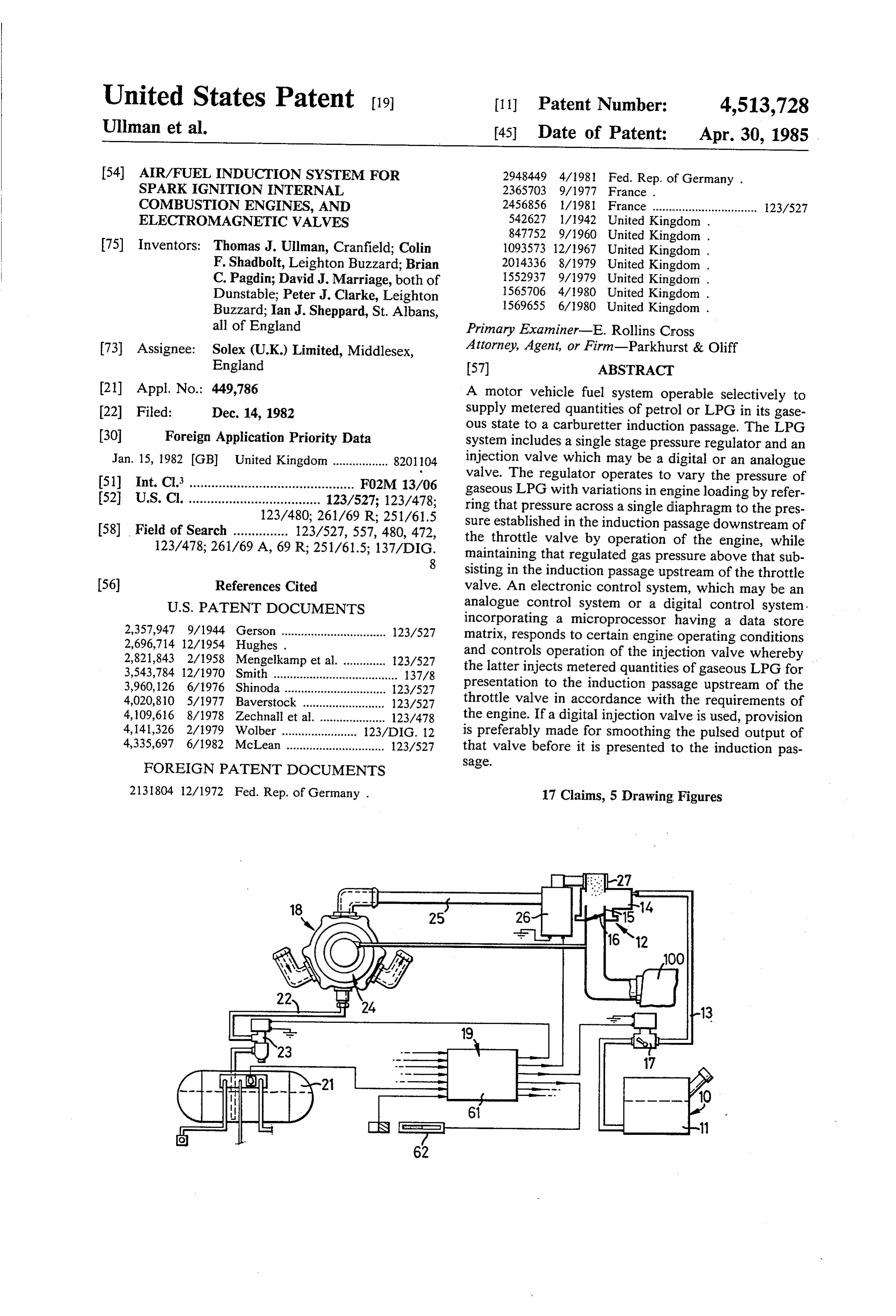
ing conditions and operable to control operation of said tion passage 15 and a driver-operable throttle valve 16 digital injection valve in accordance with those condi in the passage 15 whereby the driver controls flow to tions such that the volumetric flow rate at which said the inlet manifold of the engine 100 of a mixture of air gaseous fuel is injected for presentation to said location which is drawn into the induction passage 15 through is matched to the operational requirements of the en the usual air cleaner by operation of the engine 100 and gine; wherein gaseous fuel flow smoothing means are petrol which is drawn into the induction passage 15 provided within said conduit means between said injec from the float chamber 14 through a metering section tion valve and said induction passage whereby the by operation of the engine 100.
pulsed output of the digital injection valve is smoothed The conversion comprises fitting a solenoid-operated prior to its presentation to said location in said induction O shut-off valve 17 into the piping 13, installing an LPG passage. system 18 and connecting its LPG delivery to the car According to another aspect of this invention an buretter induction passage 15 adjacent the upstream end electromagnetic digital valve is controlled so that, for of that passage, and installing an electronic control all operations below a predetermined "mark space ra system 19 which includes various transducers which tio” (M.S.R.), it is operated with a constant opening 15 sense respective operating parameters of the engine 100 pulse width at a respective frequency selected automati and emit control signals derived from the sensed operat cally from within the range of operating frequencies of ing parameters.
the valve in accordance with certain external control The LPG system 18 comprises an LPG storage tank parameters, whereas, for all operations at or above said 21, a liquid transfer pipeline 22 including a solenoid predetermined M.S.R., it is operated at a maximum 20 operated shut-off valve 23, a vaporizer/pressure regula frequency, the opening pulse width being selected auto tor unit 24, piping 25 by which vaporized LPG is con matically in accordance with the external control pa veyed from the unit 24 to an injection valve 26 and rameters. means 27 by which vaporized LPG injected by the According to yet another aspect of this invention, injection valve 26 is directed into the induction passage operation of an internal combustion engine digital elec 25 15 of the carburetter 12 at a location upstream of the tromagnetic fluid fuel injection valve is controlled at a carburetter throat in the sense of the direction of air frequency which is not synchronised with the speed of flow through the induction passage 15. It is desirable the engine by a control arrangement comprising a mi that the vaporizer is effective to change the liquid LPG croprocessor having a data store matrix which is ad into a dry fuel gas with substantially no liquid phase so dressed by electrical signals indicative of measured 30 that the injection valve 26 can operate predictably to values of engine speed and engine load, the micro meter the injection of that fuel.
processor responding automatically to determine the The LPG storage tank 21, the liquid transfer pipeline frequency and pulse width of the digital valve driving 22 and the LPG shut-off valve 23 may be conventional signal from data stored in the matrix, the valve having a and are not described here.
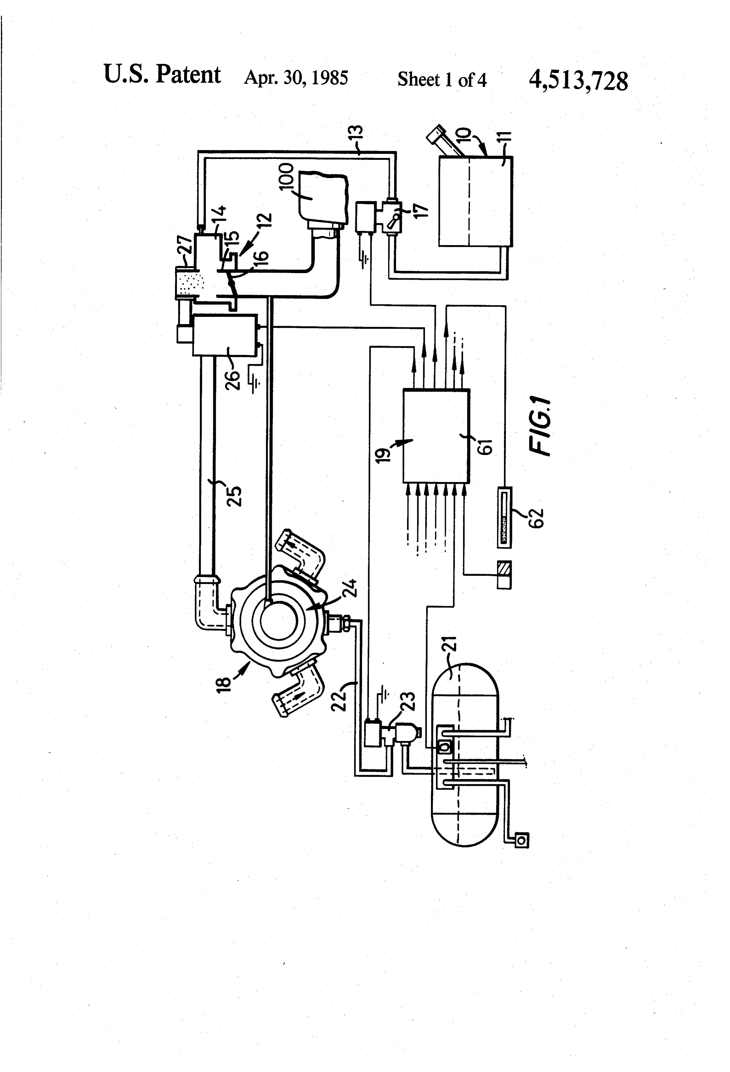
range of possible operating frequencies and pulse 35 FIG. 2 shows that the vaporizer/pressure regulator widths. unit 24 comprises a hollow casing 28 which is divided BRIEF DESCRIPTION OF THE DRAWINGS internally by a diaphragm 29 into two chambers 31 and 32. The wall of the chamber 32 that faces the diaphragm
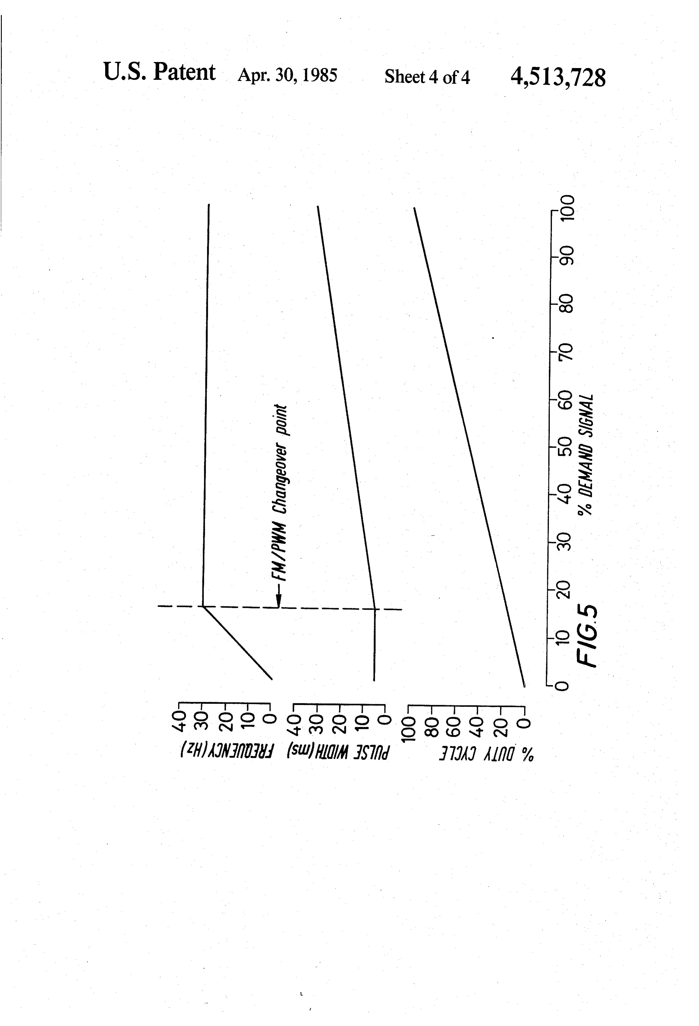
An LPG fueling system in which this invention is 29 is formed by a casting 33 which is formed with pro embodied is described now by way of example with 40 jections that form baffles projecting into the interior of reference to the accompanying drawings, of which: the chamber 32.
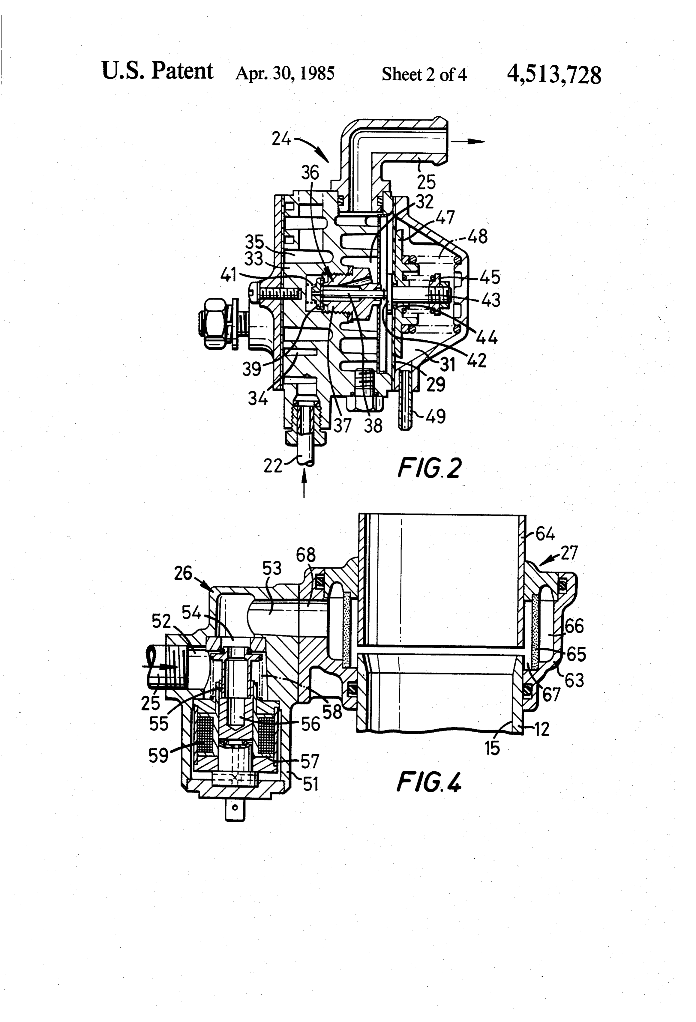
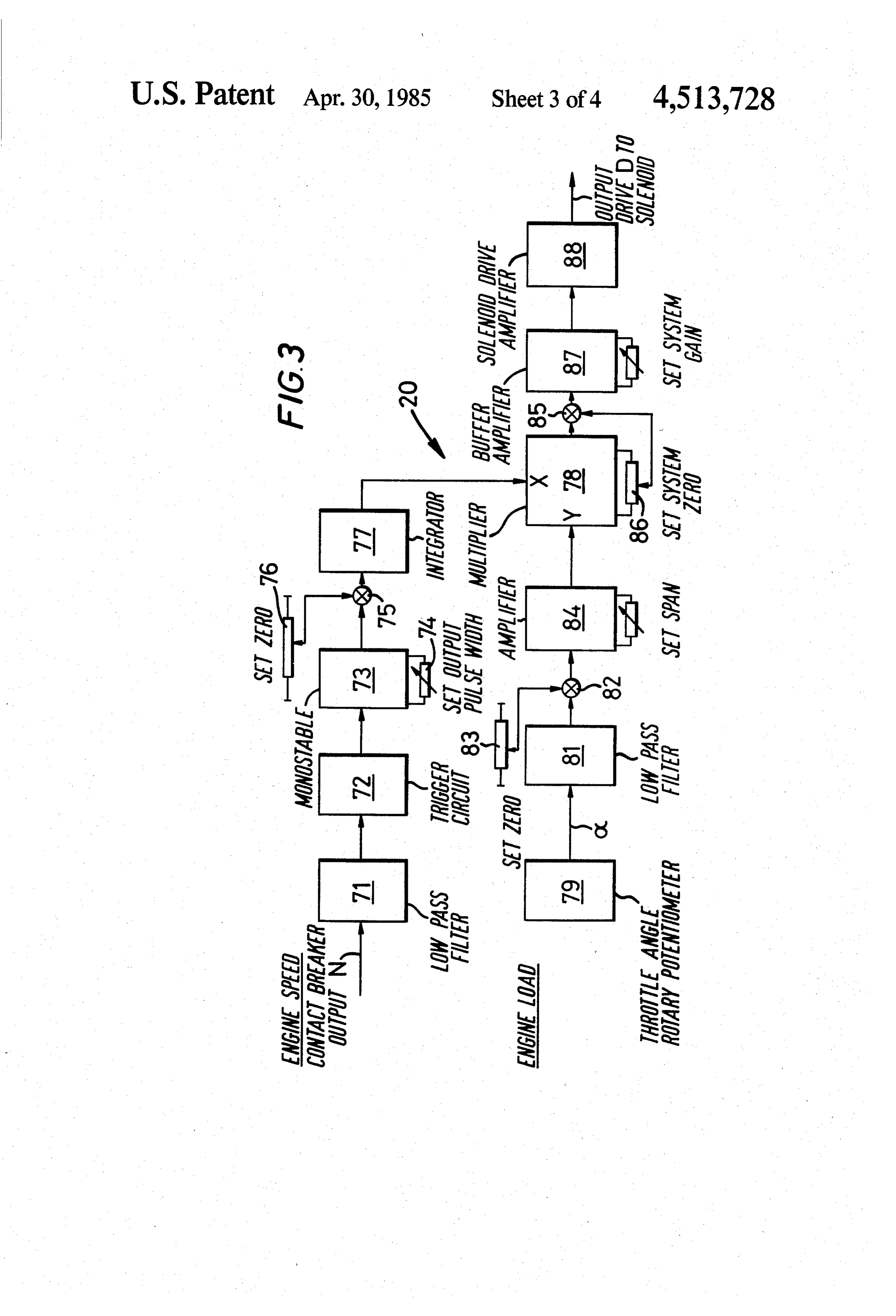
FIG. 1 is a schematic diagram of the system which Two spiral passages 34 and 35 are formed substan comprises an LPG conversion kit fitted to a spark igni tially concentrically within the casting 33. The liquid tion internal combustion engine installation which in transfer pipeline 22 is connected into the spiral passage cludes a petrol supply system incorporating a carburet 45 34 which leads to the high pressure, or inlet side of an ter; expansion valve 36 which is mounted in the casting 33, FIG. 2 is a cross-section of the vaporizer/pressure substantially at the centre thereof and which controls regulating unit of the system shown in FIG. 1; fluid flow from the spiral passage 34 into the chamber FIG. 3 is a diagram of an analogue electronic control 32. The spiral passage 35, which has a substantially system for controlling operation of the injection valve 50 larger cross sectional area than the spiral passage 34, is for the system shown in FIG. 1; connected into the cooling water system of the engine FIG. 4 is a cross-section of assembly of a digital injec 100 and extends between the turns of the spiral passage tion valve, which serves as the injection valve in the 34.
system shown in FIG. 1, and of the upstream end of the The expansion valve 36 comprises a valve body 37 carburetter of that system; and 55 with through passages formed in it, and an obturating FIG. 5 is a graphical illustration of operation of the member 38 which slides within a central one of the digital injection valve shown in FIG. 4. passages in the valve body 37. The obturating member DETAILED DESCRIPTION OF THE 38 projects from both ends of the valve body 37 and PREFERRED EMBODIMENT carries a sealing head 39 at its end which communicates 60 with the passage 34. The sealing head 39 is urged by a
FIG. 1 shows a dual fueling system of a motor vehicle coil spring 41 to seat on the valve body 37 and thereby formed by fitting an LPG conversion kit to the original isolate the passage 34 from the through passages petrol system of the spark ignition internal combustion through the valve body 37.
engine 100. A disc 42 is mounted at one end of a rod 43 which The original petrol system 10 comprises a petrol tank 65 extends slidably through a bush 44 which is fitted into a 11, a carburetter 12 and piping 13 by which petrol is central aperture of the diaphragm 29. The disc 42 is conveyed from the tank 11 to a float chamber 14 of the within the chamber 32. The rod 43 carries a reaction carburetter 12. The carburetter 12 has an air/fuel induc ring 45 within the chamber 32. A coil spring 46 reacts
Page 9
against the reaction ring 45 and urges an annular disc 47 The injection valve 26 is electronically controlled by against the diaphragm 29 so that the central part of the the control system 19 with the flow of gaseous LPG diaphragm 29 is sandwiched between the disc 42 and fluid through it being regulated by operation of a sole the annular disc 47 in a gas-tight manner. A third coil noid. The flow of gaseous LPG to the carburetter in spring 48 urges the annular disc 47, and hence the dia duction passage 15 is regulated by alteration of the phragm 29 towards the casting 33. effective bleed area available for the gas flow through The chamber 31 is connected by a pipe 49 to the inlet the injection valve 26 which is adapted to shut off the manifold of the engine downstream of the carburetter flow of gaseous LPG to the carburetter 12 for the mini throttle valve 16. The chamber 32 communicates with mum flow condition and is operable to allow flow to the the piping 25. The spiral passage 35, which is connected O carburetter induction passage 15 up to a maximum flow. into the engine cooling water circuit, hence comprises The actual effective bleed area for the flow of gaseous one part of a heat exchange section of the vaporizer/- LPG through the injection valve 26 at any instant is pressure regulator unit 24 by which the LPG in the determined by the electronic control system 19 and is a passage 34 and gaseous LPG in the chamber 32 are function of measured engine speed and a load sensing brought into heat exchange with water in the engine 5 parameter, conveniently the angle of the throttle plate cooling water circuit. The engine cooling water serves of the throttle valve 16 although any other engine load as a source of heat for vaporization of the liquid LPG parameters such as engine inlet manifold pressure could during expansion of that LPG as it flows from the pas be used.
sage 34 to the chamber 32 through the expansion valve FIG. 3 is a block diagram illustrating an analogue 36. electronic control circuit 20 which may form part of the The arrangement of the diaphragm 29 and the third electronic control system 19 and by which measured coil spring 48 is such that a constant pressure differen values of engine speed derived from the vehicle engine tial is maintained across the diaphragm 29. Hence the contact breaker output N and of engine load derived pressure of gaseous LPG in the chamber 32 is regulated from a transducer output a are used to generate an so that it varies with variations in the inlet manifold 25 appropriate solenoid drive signal by which the solenoid depression but in the opposite sense to the changes in is energised to operate the injection valve 26 for the the inlet manifold depression. Thus, for an increasing required flow of gaseous LPG.
power requirement from the engine 100, an increasing The engine speed signal N comprises a series of pulses pressure gaseous LPG feed to the injection valve 26 is having a frequency which is the measure of engine available allowing a potential increase in flow of gase 30 speed. The signal N is conditioned by being passed ous LPG to the engine. The pressure of gaseous LPG in through a low pass filter 71, where unwanted high fre the chamber 32, and hence in the conduit formed by the quency components are removed, to a trigger circuit 72 piping 25 leading to the injection valve 26, is also regu which produces a pulse output having a frequency lated so that it is between the pressure in the storage which depends on the signal received from the filter 71. tank 21 and the pressure in the carburetter induction 35 The pulse output from the trigger circuit 72 is fed to a passage 15 upstream of the carburetter throat. In a prac monostable device 73 which emits a pulse output at the tical application of this embodiment of this invention, same frequency as the output from the trigger circuit 72 the pressure of gaseous LPG in the chamber 32 is modu and having a constant pulse length which is determined lated to 0.8 bar (12 p.s. i.) above the absolute pressure in by the setting of a variable resistance 74 with which the the engine inlet manifold. Thus as full load of the engine monostable device 73 is provided. The output signal 100, the pressure of gaseous LPG in the chamber 32 is from the monostable device 73 is mixed in a mixer 75 approximately 0.8 bar (12 p.s. i.), and at low loads or idle with a reference voltage obtained from a tapping of a conditions it is approximately 0.2 bar (3 p.s. i.). potentiometer 76 whereby that signal is located relative Connection of the chamber 31 to the inlet manifold of to zero prior to feeding it to the input of an integrator the engine 100, as distinct from connecting that cham 45 77. The output of the integrator 77, which is propor ber to the surrounding atmosphere under the bonnet of tional to the average number of pulses per unit time and the motor vehicle, avoids undesirable influences on fuel hence to the frequency of the engine speed signal N, is flow to the engine 100 that may follow from changes in fed to one input of a multiplier 78. the pressure under the bonnet of the motor vehicle and A rotary potentiometer 79, which is mounted on the from the restriction due to the air cleaner. SO spindle of the throttle valve 16, serves as the transducer The arrangement of the rod 43 that is axially-slidable having the output a which is a measure of engine load. in the bush 44, the disc 42 and 47, the abutment ring 45, The output signal a is passed through a low pass filter the coil spring 46 and the portion of the surface of the 81 whereby unwanted high frequency components are chamber 31 that faces the end of the rod 43 in that removed. The output from the filter 81 is mixed in a chamber 31, serves as an over pressure relief valve for 55 mixer 82 with a reference voltage obtained from a tap the vaporizer/pressure regulator unit 24 which protects ping of a potentiometer 83 whereby that output signal is that part of the system between the expansion valve 36 located relative to zero. The signal is then amplified in and the carburetter 12 from being subjected to the LPG an amplifier 84 to a level at which it is compatible with storage tank pressure in the unlikely event of a failure of the output from the integrator 77, and is then fed to the regulator. The bush 44 is permeable by gaseous 60 another input of the multiplier 78.
LPG and serves as a vent path to the chamber 31 for The output signals from the integrator 77 and the gaseous LPG in the chamber 32 when the pressure in amplifier84, which are indicative respectfully of engine the chamber 32 exceeds a predetermined maximum speed and engine load, are multiplied together by the causing the spring 46 to collapse so that the diaphragm multiplier 78. The output from the multiplier 78 is 29 separates from the disc 42. Any gaseous LPG vented 65 mixed in a mixer 85 with a reference voltage, which is from the chamber 32 via the bush 44 is directed to the tapped from a potentiometer 86 which is connected into engine inlet manifold via the chamber 31 and the pipe the multiplier 78, whereby that output is located rela 49. tive to zero, and then is fed through a buffer amplifier87
Page 10
to an amplifier 88 which generates an analogue output demand requirement of the engine 100 (say approxi signal which is the solenoid drive signal D. mately 15% as is illustrated graphically in FIG. 5), the A solenoid drive signal produced by the circuit 20 valve 55 is operated with a constant opening pulse illustrated in FIG. 3 is appropriate for energising an width at a frequency within a range of frequencies that analogue type injection valve. However such valves increases as the engine fuel demand requirement in have problems due to friction which do not arise if a creases. This arrangement is illustrated by the portions digital type injection valve is employed. Accordingly of the upper two curves in FIG. 5 to the left hand side we prefer to use a digital type injection valve such as is of the dotted line. On the other hand for all other opera illustrated in FIG. 4. Whereas the effective bleed area of tions of the valve 55, that is to say operations to the an analogue valve is the cross-sectional area of the space 10 right of the dotted line in FIG. 5, the solenoid drive between the movable valve element and an orifice with signal is at maximum frequency and a pulse width which it co-operates, the location of that valve element which increases as the engine fuel demand requirement relative to the orifice being a function of the magnitude increases.
of the D.C. current (viz. the solenoid drive signal) by Although the electronic control system 19 could which the solenoid winding is energised to locate that 15 incorporate an analogue control circuit similar to the valve element, the effective bleed area of a digital valve; circuit 20 illustrated in FIG. 3 but modified to provide which continually opens and closes, is related to the analogue to digital conversion means for further pro frequency of its opening and the duration of each open cessing the output of the multiplier in order to convert ing which in turn is determined by the width of the that output to a pulsed solenoid drive signal having a energising electrical pulse that is the respective solenoid 20 frequency and pulse width for the sensed engine condi drive signal. The analogue output signal from the sole tions according to the graphs shown in FIG. 5, we noid drive signal generating amplifier 88 would be con prefer to use a digital control system by which the mea verted into an appropriate pulse solenoid drive signal by sured engine speed and engine load parameter signals an analogue to digital converter. are fed each to a respective input terminal of a basic FIG. 4 shows that the digital injection valve com 25 pulse frequency and pulse width memory device 61 (see prises a hollow body 51 having an internal cavity, an FIG. 1). The device 61 is a microprocessor electronic inlet port 52 and an outlet port 53 formed therein, the device which comprises a compact digital store of opti inlet and outlet ports 52 and 53 communicating with the mum pulse widths and pulse frequencies for all engine internal cavity on either side of an orifice 54 in a mem running conditions substantially as illustrated by the ber which spans the internal cavity. A valve 55 is 30 graphs in FIG. 5, in the form of a matrix memory store mounted on a plunger 56 of magnetic material which is of injector pulse frequencies and pulse widths tailored slidable in the bore of a tubular core 57 which is to match the engine requirements. The microprocessor mounted in the internal cavity coaxially with the orifice device 61 is adapted, based on the two input parameters 54 and on the same side of the orifice 54 as the inlet port of engine speed and engine load, to emit an output 52. The valve 55 is urged to seat in the orifice 54 by a 35 pulsed signal which is the solenoid drive signal appro coil spring 58. A solenoid winding 59 is wound around priate for the sensed engine condition as illustrated in - the core 57 and is arranged to unseat the valve 55, FIG. 5.
against the action of the coil spring 58 when it is energ The electronic control system 19 provides other facil ised, the plunger 56 serving as an armature of the sole ities including the selection of the fuel being used, be it noid. The bore of the tubular core 57 is closed at its end petrol or LPG, and thus control of the opening of the remote from the orifice 54 by a plug which is recessed selected one of the petrol solenoid shut-off valve 17 and at its end which is nearer to the orifice 54. An O-ring is the LPG solenoid shut-off valve 23. The control system seated in the recess and serves as a resilient cushion 19 conveniently includes a switch 62 on the vehicle which prevents metal to metal contact of the plunger 56 dash board by which the fuel is selected. with the plug. 45 FIG. 4 shows that the outlet port 53 of the digital The solenoid winding 59 is energised by a pulsed injection valve 26 is connected to the carburetter induc drive signal generated by the control system 19 so that tion passage 15 through a diffuser arrangement by the valve 55 is repreatedly unseated and reseated to which the pulsed output of the digital injection valve 26 allow pulses of gaseous LPG to pass through the orifice is smoothed before entering the carburetter induction 54 to the outlet port 53. The effective bleed area of the 50 passage 15.
valve 55 for a certain period of operation of that valve The diffuser arrangement comprises a casing 63 55 is related to the M.S.R. of the pulse drive signal, that which is fitted onto that part of the carburetter body is to say it is related to the ratio of the total of the dura that forms the upper end of the induction passage 15 and tions of all solenoid energising pulses during that period which receives an air supply duct 64 by which a supply to the remainder of that period, and hence is related to 55 of clean air for the engine 100 is conveyed to the up the frequency and pulse width of the pulsed drive sig stream end of the carburetter induction passage 15. The nal. diffuser arrangement circumferentially surrounds the We have not been able to adequately match the sup upper end of the induction passage 15. There is a cir ply of gaseous LPG produced by operation of the digi cumferentially continuous gap between the duct 64 and tal injection valve 26 to the requirements of the engine 60 the body of the carburetter 12. The duct 64 is located 100 by merely altering the pulse width of the solenoid relative to the induction passage 15 by the casing 63 drive signal whilst operating the solenoid valve at maxi which forms an annular gallery around the duct 64 and mum frequency. In order to increase the dynamic range the carburetter body, there being communication be of operation of the digital injection valve 26, and thus tween that gallery and the induction passage 15 via the more adequately match the resultant flow of gaseous 65 gap. A cylindrical wall of porous material 65 divides the LPG to the requirements of the engine 100, the elec annular gallery into two coaxial annular chambers 66 tronic control system 19 is arranged so that, for all and 67 and hence forms the radially inner boundary of operations of the valve 55 below a predetermined fuel the outer annular chamber 66. A port 68 in the side of
Page 11
the casing 63 communicates with the outlet port 53 of gine load, the microprocessor responding automatically the digital injection valve 26 and connects that outlet to provide the appropriate valve driving signal derived port 53 to the outer annular chamber 66. Hence the from data stored in the matrix. piping by which the output of the injection valve 26 is 4. An air/fuel induction system according to claim 2, connected to the diffuser 27 communicates freely with 5 wherein the injection valve is controlled electromagnet the outer annular chamber 66. Thus the pulsed output of ically by said control means and is a digital valve, said gaseous LPG is conveyed from the outlet port 53 to the digital valve being operable to continually open and outer annular chamber 66 around which it circulates so close at a controlled frequency of opening and duration that it is spread circumferentially therearound. The of each opening so as to control fuel flow in accordance gaseous LPG passes through the porous wall 65 into the O with the frequency of its opening and the duration of inner annular chamber 67 and from there into the carbu each opening.
retter induction passage 15 through the gap between the 5. An air/fuel induction system according to claim 4, carburetter 12 and the air duct 64, whereby it is pres wherein gas flow smoothing means are provided for ented to the induction passage 15, the gap Serving as an smoothing the pulsed output of the digital injection inlet to the induction passage 15. The length of the flow 15 valve prior to its presentation to said location in said path for the output of gaseous LPG from the outlet port induction passage.
53 of the digitalinjection valve 26 into the outer annular 6. An air/fuel induction system according to claim 4, chamber 66 is selected carefully and may be long in wherein the control means comprise a digital drive order to further the smoothing of the pulsed output circuit including a microprocessor having a data store from the digital valve. matrix which is addressed by electrical signals indica The LPG system 18 may be provided with a drain tive of measured values of engine speed and engine plug but it may not be necessary as the relatively high load, the microprocessor responding automatically to pressure flow of LPG may purge residuals from the provide the appropriate valve driving signal derived LPG flow passages. from data stored in the matrix. We claim: 25 7. An air/fuel induction system according to claim 6, 1. An air/fuel induction system for a spark ignition wherein the digital valve control means are arranged so internal combustion engine, the system comprising an that, for all operations of the digital valve below a pre air/fuel induction passage with a driver-operable throt determined fuel demand requirement of the engine, the tle valve therein, and a fuel system by which gaseous valve is operated with a constant opening pulse width at fuel is presented to a location in the induction passage; 30 a respective frequency selected automatically from the fuel system comprising pressure regulating means within the range of operating frequencies of the valve in operable to regulate the pressure of the gaseous fuel and accordance with the measured values of engine speed conduit means by which the gaseous fuel is conveyed to and engine load, whereas for all operations of the valve said location, the pressure regulating means being at or above said predetermined fuel demand require adapted to respond to changes in a depression which is 35 ment, the valve is operated at maximum frequency, the established downstream of the throttle valve by opera opening pulse width being selected automatically in tion of the engine and to effect a consequent change in accordance with the measured values of engine speed the regulated pressure of the gaseous fuel such that it and engine load.
varies in the opposite sense to variations of said depres 8. An air/fuel induction system according to claim 4, sion; wherein the pressure regulating means are adapted wherein the digital valve control means are arranged so to maintain the gaseous fuel at a pressure higher than that, for all operations of the digital valve below a pre that established at said location by operation of the determined fuel demand requirement of the engine, the engine and comprise a single movable wall which sepa valve is operated with a constant opening pulse width at rates two chambers, one of the two chambers contain a respective frequency selected automatically within ing gaseous fuel at the regulated pressure and the other 45 the range of operating frequencies of the valve in accor chamber being in communication with said induction dance with measured values of engine speed and engine passage downstream of said throttle valve, there being load, whereas for all operations of the valve at or above an injection valve in said conduit means operable to said predetermined fuel demand requirement, the valve effect injection of metered quantities of said gaseous is operated at maximum frequency, the opening pulse fuel whereby said gaseous fuel is presented to said loca SO width being selected automatically in accordance with tion, and control means responsive to certain engine the measured values of engine speed and engine load. operating conditions and operable to control operation 9. An air/fuel induction system according to claim 1, of said injection valve in accordance with those condi wherein the injection valve is controlled electromagnet tions such that the volumetric flow rate at which said ically by said control means.
gaseous fuel is injected is matched to the operational 55 10. An air/fuel induction system according to claim requirements of the engine. 9, wherein the control means comprise an analogue 2. An air/fuel induction system according to claim 1, valve drive circuit adapted to process an electrical input wherein the pressure regulating means include a pres signal which is the product of electrical signals indica sure relief valve operable to vent said one chamber into tive of measured values of engine speed and engine said other chamber and hence to said induction passage 60 load, into a valve driving signal. downstream of the throttle valve, should the pressure in 11. An air/fuel induction system according to claim said one chamber exceed a predetermined maximum. 9, wherein the control means comprise a digital drive 3. An air/fuel induction system according to claim 2, circuit including a microprocessor having a data store wherein the injection valve is controlled electromagnet matrix which is addressed by electrical signals indica ically by said control means which comprise a digital 65 tive of measured values of engine speed and engine drive circuit including a microprocessor having a data load, the microprocessor responding automatically to store matrix which is addressed by electrical signals provide the appropriate valve driving signal derived indicative of measured values of engine speed and en from data stored in the matrix.
Page 12
12. An air/fuel induction system according to claim engine, the valve is operated with a constant opening 9, wherein the injection valve is a digital valve, said pulse width at a respective frequency selected automati digital valve being operable to continually open and cally from within the range of operating frequencies of close at a controlled frequency of opening and duration the valve in accordance with measured values of engine of each opening so as to control fuel flow in accordance speed and engine load, whereas for all operations of the with the frequency of its opening and the duration of valve at or above said predetermined fuel demand re each opening.
13. An air/fuel induction system according to claim quency, the the quirement, valve is operated at maximum fre opening pulse width being selected auto 12, wherein gas flow smoothing means are provided for matically in accordance with the measured values of smoothing the pulsed output of the digital injection 10 engine speed and engine load.
valve prior to its presentation to said location in said 17. An air/fuel induction system for a spark ignition induction passage. internal combustion engine, the system comprising an 14. An air/fuel induction system according to claim air/fuel induction passage with a driver-operable throt 12, wherein the control means comprise a digital drive tle valve therein, and a fuel system by which gaseous circuit including a microprocessor having a data store 15 matrix which is addressed by electrical signals indica the fuel is presented to a location in the induction passage; tive of measured values of engine speed and engine gaseous fuel system including conduit means by which the load, the microprocessor responding automatically to fuel is conveyed to said location, a digital injec provide the appropriate valve driving signal derived tion valve in said conduit means operable to effectinjec from data stored in the matrix. 20 tion of metered quantities of said gaseous fuel whereby 15. An air/fuel induction system according to claim said gaseous fuel is presented to said location, said digi 14, wherein the digital valve control means are ar tal valve being operable to continually open and close at ranged so that, for all operations of the digital valve a controlled frequency of opening and duration of each below a predetermined fuel demand requirement of the opening so as to control fuel flow in accordance with engine, the valve is operated with a constant opening 25 the frequency of its opening and the duration of each pulse width at a respective frequency selected automati opening, and control means responsive to certain engine cally from within the range of operating frequencies of operating conditions and operable to control operation the valve in accordance with the measured values of of said digital injection valve in accordance with those engine speed and engine load, whereas for all operations conditions such that the volumetric flow rate at which of the valve at or above said predetermined fuel demand 30 said gaseous fuel is injected for presentation to said requirement, the valve is operated at maximum fre location is matched to the operational requirements of quency, the opening pulse width being selected auto the engine; wherein gaseous fuel flow diffusion means matically in accordance with the measured values of are provided within said conduit means between said engine speed and engine load. injection valve and said induction passage whereby the 16. An air/fuel induction system according to claim 35 pulsed output of the digital injection valve is smoothed 12, wherein the digital valve control means are ar prior to its presentation to said location in said injection ranged so that, for all operations of the digital valve passage.
below a predetermined fuel demand requirement of the k k k se k
Provenance
- Collection
- Cited prior art
- Original PDF
- patentimages.storage.googleapis.com →
- Filed
- 1982-12-14
- Pages
- 12
- Method
- pdftotext (the PDF's own text layer) + pdftoppm 300dpi page scans
- Source
- Google Patents bibliographic record
- Granted
- 1985-04-30
- Inventors
- Thomas J. Ullman; Colin F. Shadbolt; Brian C. Pagdin; David J. Marriage; Peter J. Clarke; Ian J. Sheppard; Solex UK Ltd
- Transcribed from
- patentimages.storage.googleapis.com →