patent · US4496787
Method and device for collecting and exploiting solar radiation
29 January 1985
Page 1 — bibliographic record
United States Patent (19) 11 Patent Number: 4496,787 Touchais et al. (45) Date of Patent: Jan. 29, 1985 54 METHOD AND DEVICE FOR COLLECTING FOREIGN PATENT DOCUMENTS
AND EXPLOITING SOLAR RADATION
76 Inventors: Maurice Touchais, 1706 Chemin du 2458768 2/1981 France ................................ 126/440 Pioulier, 06140 Vence; Madeleine OTHER PUBLICATIONS
Djelalian, 10 Impasse Abovian, 13015 Marseille, both of France M. A. Duguay, "Solar Electricity: The Hybrid System 21 Appl. No.: 536,158 Approach'', American Scientist, vol. 65, pp. 422-427,
(22) PCT Filed: Dec. 16, 1982 Primary Examiner-Aaron Weisstuch (86). PCT No.: PCT/FR82/00212 Attorney, Agent, or Firm-Karl W. Flocks; Sheridan Neimark; A. Fred Starobin
S 371 Date: Aug. 16, 1983 (57) ABSTRACT S 102(e) Date: Aug. 16, 1983 The method and apparatus of the invention are intended 87). PCT Pub. No.: WO83/02310 to collect, in the intermediary space comprised between
the transparent cover and the absorbing receiver sur faces of a solar insolator, the substantially parallel light (30) Foreign Application Priority Data beams from the sun by thermally insulated and orient able optical means for tracking said beams, to make said
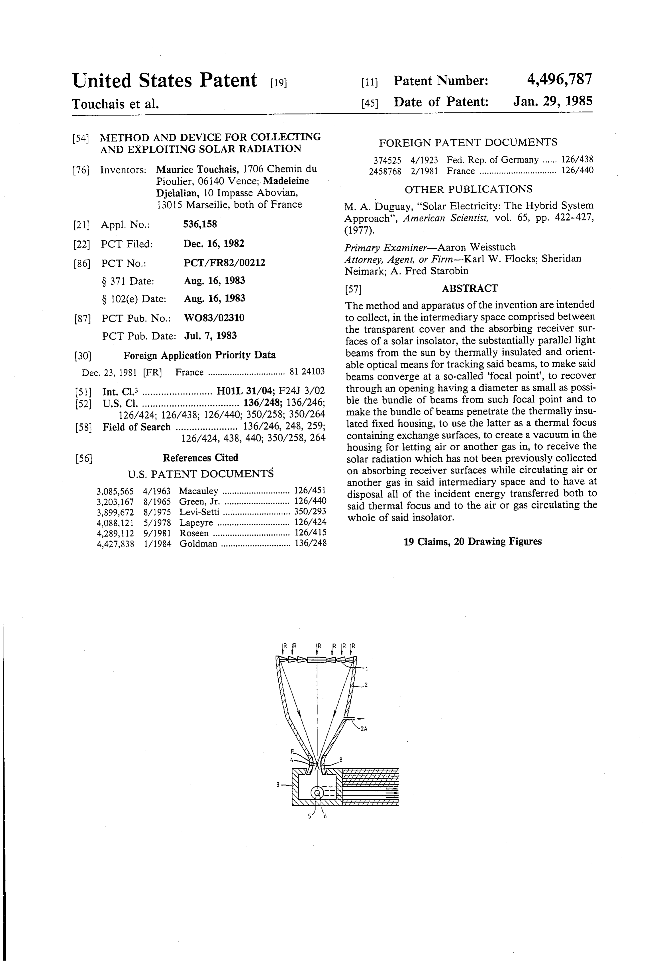
Dec. 23, 1981 (FR) France ................................ 8124103 beams converge at a so-called "focal point', to recover 51 Int. Cl........................... H01L 31/04; F24J 3/02 through an opening having a diameter as small as possi 52 U.S. Cl. .................................... 136/248; 136/246; ble the bundle of beams from such focal point and to 126/424; 126/438; 126/440; 350/258; 350/264 make the bundle of beams penetrate the thermally insu 58) Field of Search ....................... 136/246, 248, 259; lated fixed housing, to use the latter as a thermal focus 126/424, 438, 440; 350/258, 264 containing exchange surfaces, to create a vacuum in the housing for letting air or another gas in, to receive the 56) References Cited solar radiation which has not been previously collected
another gas in said intermediary space and to have at 3,085,565 4/1963 Macauley ..... - 126/451 disposal all of the incident energy transferred both to 3,203,167 8/1965 Green, Jr. ..... ... 126/440 said thermal focus and to the air or gas circulating the 3,899,672 8/1975 Levi-Setti. ... 350/293 4,088, 121 5/1978 Lapeyre .... ... 126/424 whole of said insolator.
4,289,112 9/1981 Roseen ..... ... 126/415 4,427,838 1/1984 Goldman ............................. 136/248 19 Claims, 20 Drawing Figures
Page 2
Drawing sheet — no readable text.
Page 3
Drawing sheet — no readable text.
Page 4
Drawing sheet — no readable text.
Page 5
Drawing sheet — no readable text.
Page 6
Drawing sheet — no readable text.
Page 7
Drawing sheet — no readable text.
Page 8
Drawing sheet — no readable text.
Page 9
Drawing sheet — no readable text.
Page 10
Drawing sheet — no readable text.
Page 11
Drawing sheet — no readable text.
Page 12
Drawing sheet — no readable text.
Page 13
Drawing sheet — no readable text.
Page 14
receiving surfaces of a known type, while also circulat
METHOD AND DEVICE FOR COLLECTING AND ing the air or other gas in said intermediate space and EXPLOITING SOLAR RADATION disposing of all the incident energy transferred both inside and outside said thermal focus to the various heat
BACKGROUND OF THE INVENTION transfer fluids circulating in the whole of said insolator.
It is known for using solar energy to employ fixed According to other characteristics:
Solar cells constituting thermal converters, also called Said opening of small diameter is located substan "thermal function insolators' and hereinafter desig tially at right angles to said focal point; and nated as "insolators'. The latter generally comprise: O The concurring points of the actual or virtual rota A transparent front covering through which solar tional axes serving for the orientation motion of said radiation or incident light penetrates; optical means is placed at said focal point. For carrying Absorbent receiving surfaces which convert the en out the method:
ergy from the solar radiation into heat which is then The optical means converging the direct, almost par transferred to heat transfer fluids, gases, or various 15 allel, light radiation coming from the sun towards the liquids, in particular, air or water; focal point is selected among optical devices of the A rear thermal insulation covering. catoptric or dioptric type to permit the beam of re The transparent covering which is mainly used for flected radiation to propagate in the general direction of protection of the inside of the apparatus from bad the incident light:
weather is often designed and constructed so as to re 20 According to one advantageous form of embodiment, duce thermal losses caused by transmission to the out said optical means comprises a Fresnel lens and/or side of the thermal flux generated in the apparatus, and reflective surfaces, the reflectance of which is high also to oppose the passage of convective currents either mainly from the inside of the apparatus or from the outside trum, ininassociation the visible range and low in the infrared spec with a transparent covering located thereof.
Moreover, the interval also called "intermediate 25 at the inlet of the solar radiation. In the case of a Fresnel space' between such transparent covering and the ab lens, such covering is constituted by the lens itself More particularly, said optical means consists of a sorbent receiving surfaces is generally of a small thick wide-angle paraboloid of revolution or a reflective sur ness so as to reduce the inner convective currents which may be responsible for significant thermal losses. This is face formed of several wide-angle paraboloids of revo why heretofore various devices were placed in such 30 lution located within one another and called a "mull intermediate space for specifically combatting such tiparaboloid':
convective currents and also the transmission of the The thermally insulated enclosure designed for serv infrared radiation coming from the heated surfaces, ing as the thermal focus is traversed by fixed pipes without however giving complete satisfaction as re where heat transfer fluids circulate;
gards total utilization of incident energy 35 Said thermal focus is stationary relative to said opti
OBJECTS OF THE INVENTION
cal means except for a portion which determines a junc tion between the movable elements connected to the
However, the purpose which is to be achieved by this optical means and the fixed elements; invention is to be able to utilize to the maximum the Supplementary optical means called super-concentra overall solar radiation and consequently to maximize 40 tors are provided close to the opening, situated at said the incident energy while minimizing thermal losses. focal point so as to embrace all the convergent possibly The invention is therefore directed to a method for aberrant radiations to direct them efficiently to the focal reaching said purpose, and devices for carrying out opening so that they can penetrate into said thermal such method. focus;
An object of the invention is also an insolator using 45 The walls of the thermal focus are made of a refrac such method and such devices as well as an installation tory material absorbing the received radiation; comprising several insolators according to the inven Supplementary receiving absorbent alveolar surfaces tion with a view to having an all-purpose thermal are provided either at the outlet of the optical means, in Source available.
50 the focal opening, or in said thermal focus, either at one
SUMMARY OF THE INVENTION or the other location to reduce losses due to retransmis The method according to the invention is substan sion through the focal opening; tially characterized in that it consists, within the inter The receiving absorbent surfaces outside the optical focusing means are advantageously constituted by tubu mediate space included between the transparent cover lar alveolae very absorbent in the visible and infrared ing and the absorbent receiving surfaces of an insolator, 55 ranges to form channels running in the direction of the of collecting the almost parallel light radiations coming light radiation by an air circulation brought into a tur from the sun through a suitable optical means thermally bulent motion.
insulated and orientatable so as to follow said light According to an advantageous mode of embodiment, radiation, converging said radiation towards a point called the "focal point' whereat they form a beam, 60 a safety shielding means is provided on the optical radi gathering through an opening having as small a diame ation path.
ter as possible the beam of light radiation surrounding According to the invention there are also provided the focal point and making it penetrate into a generally solar energy cells comprising, in the intermediate space stationary thermally insulated enclosure, using the latter between the transparent covering and the absorbing as a thermal focus containing fixed exchange surfaces, 65 surfaces, one or more optical means such as defined bringing such enclosure to a negative pressure to cause above and called hereinafter "concentrators' disposed air or another gas to penetrate thereinto, receiving the in one or more rows in one of the two directions in solar radiation not picked up previously onto absorbent space, i.e. East-West or North-South.
Page 15
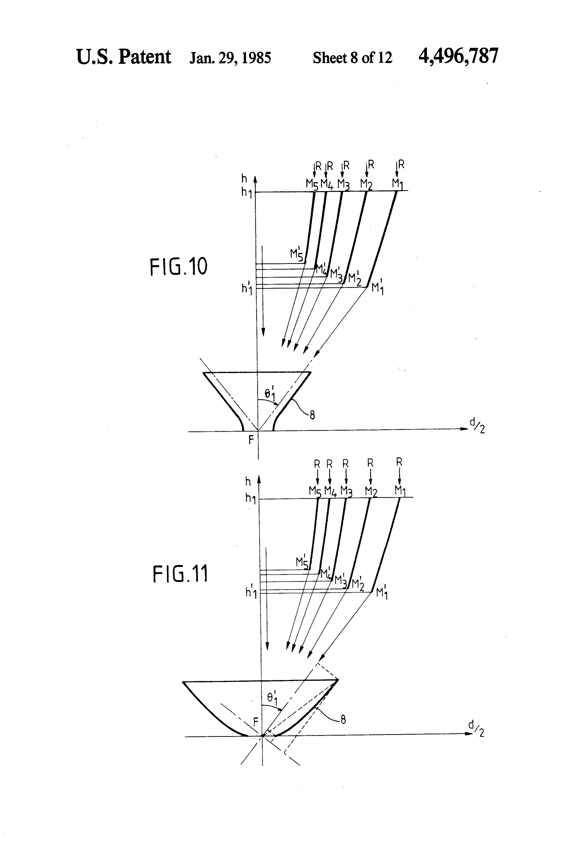
BRIEF DESCRIPTION OF THE DRAWINGS
the opening 4 for penetration of light flux into the ther mal focus 3, which would have the consequence of
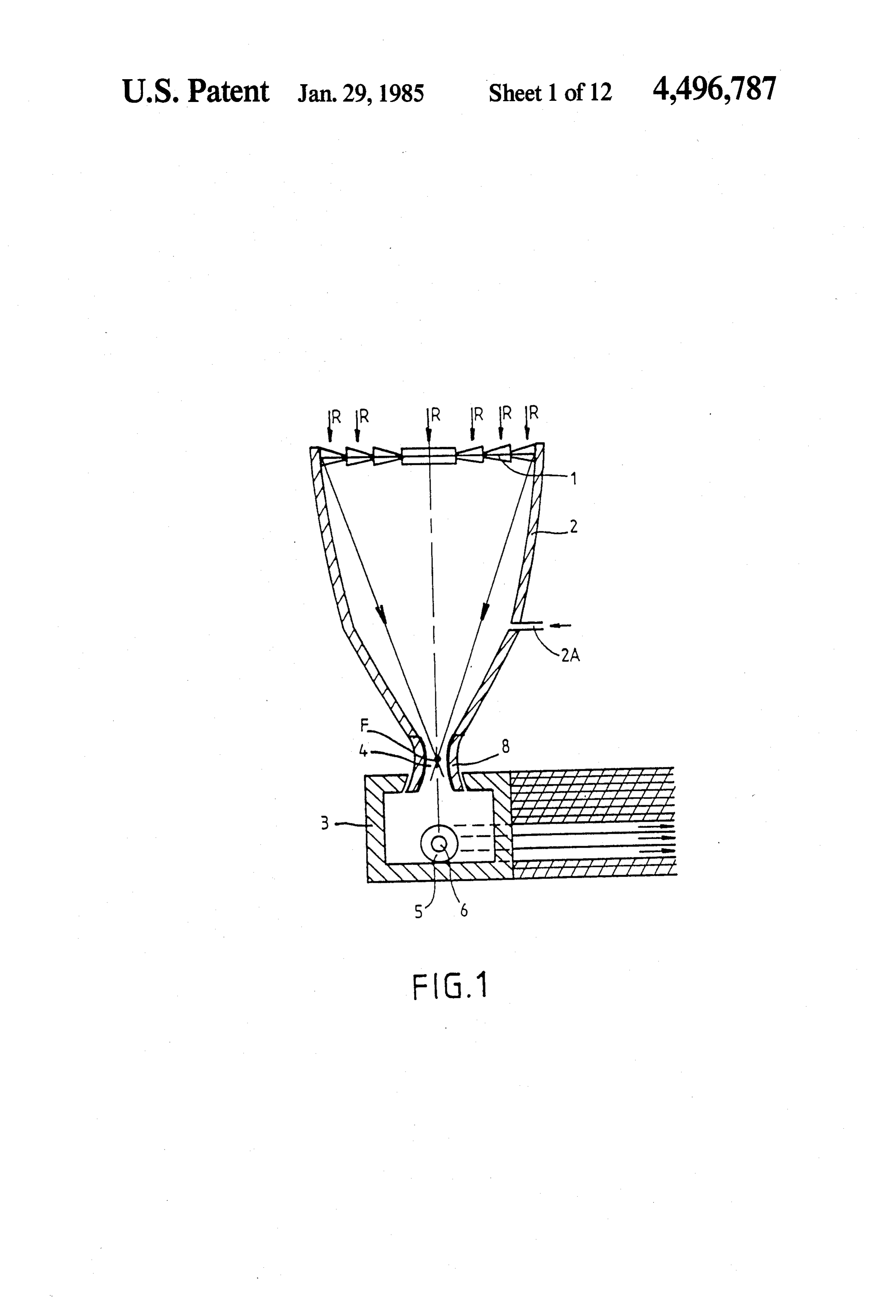
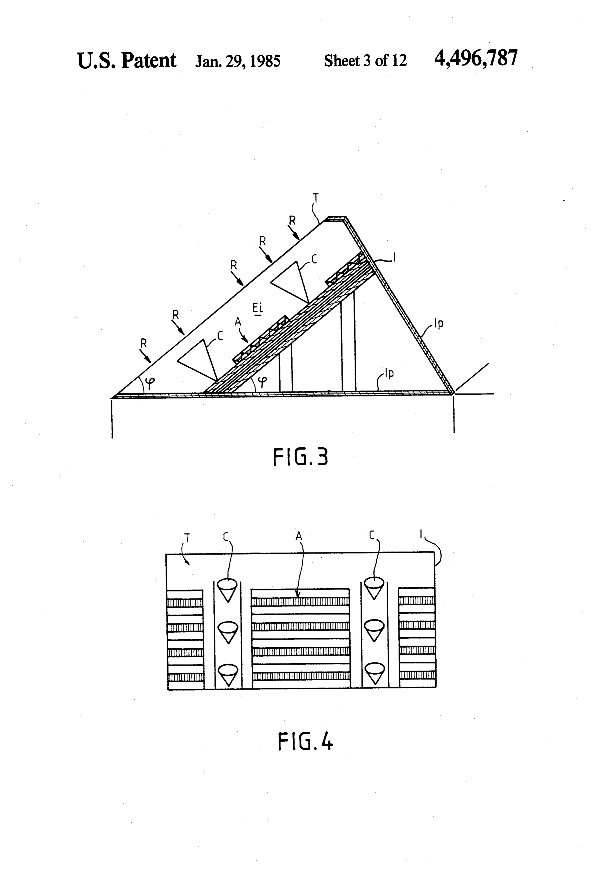
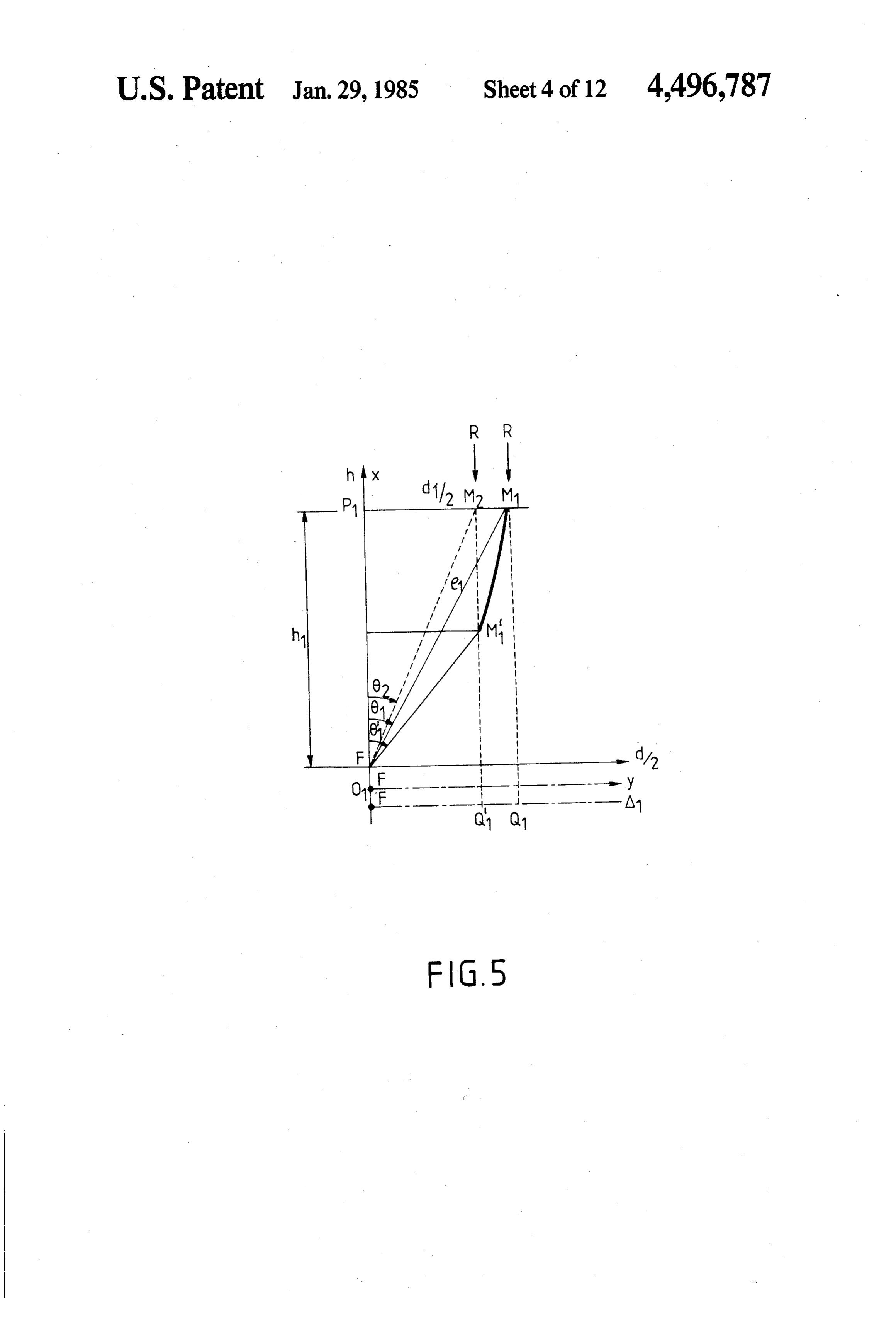
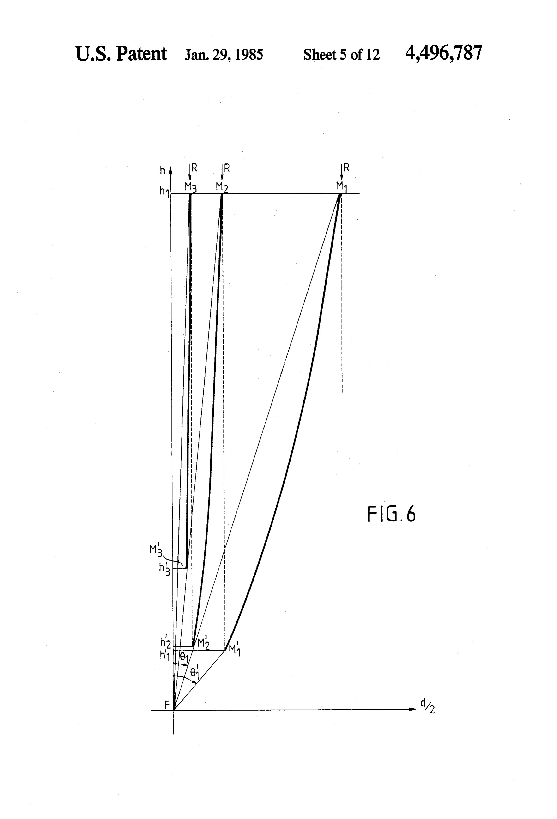
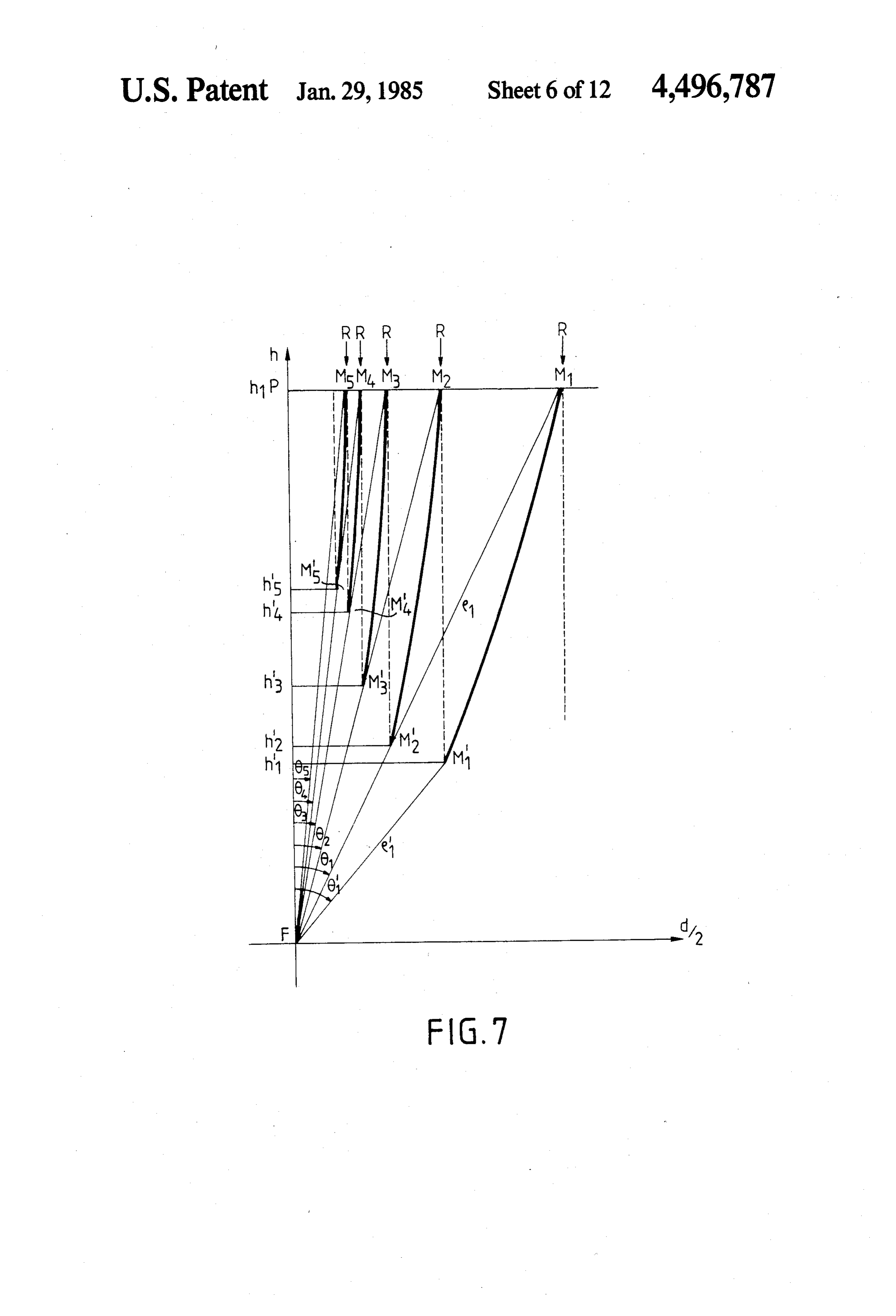
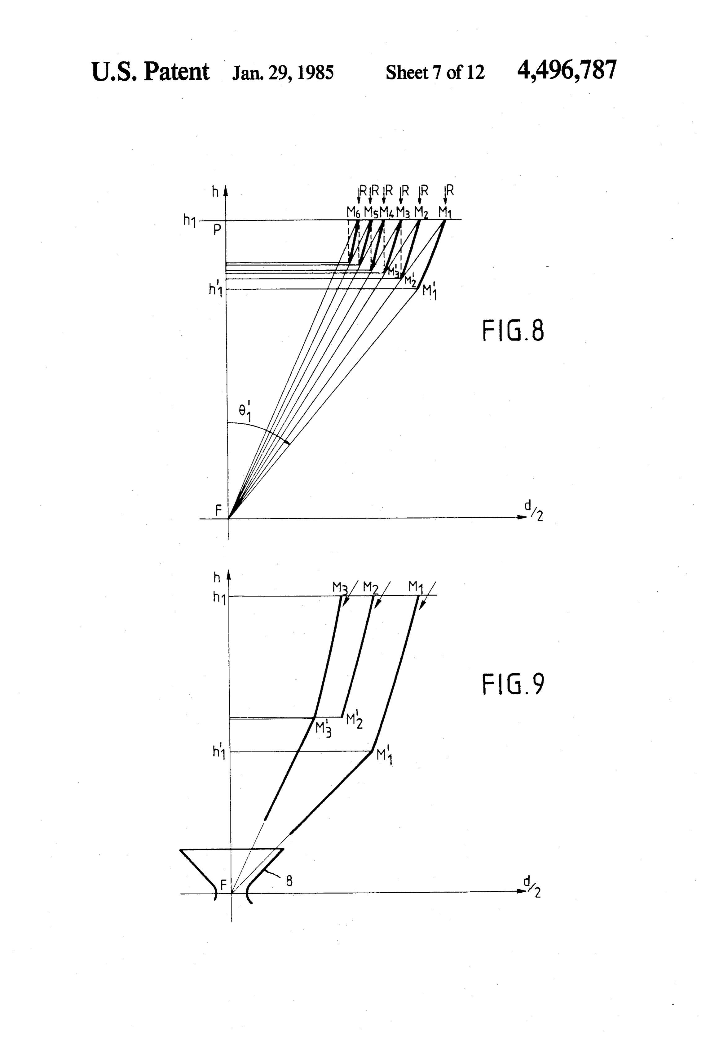
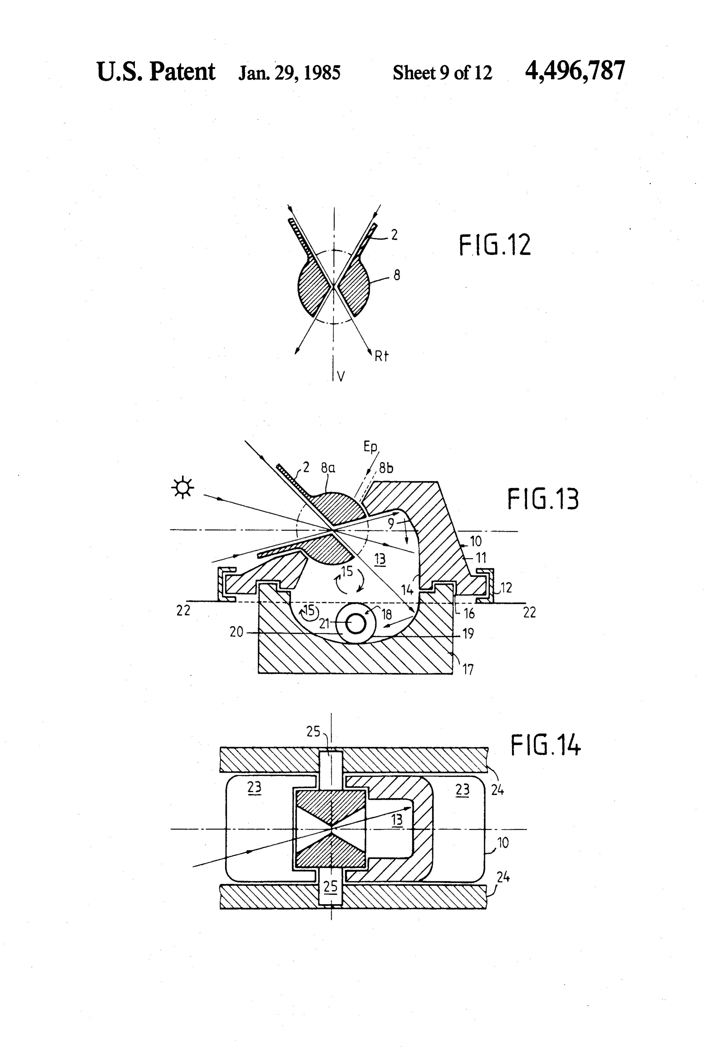
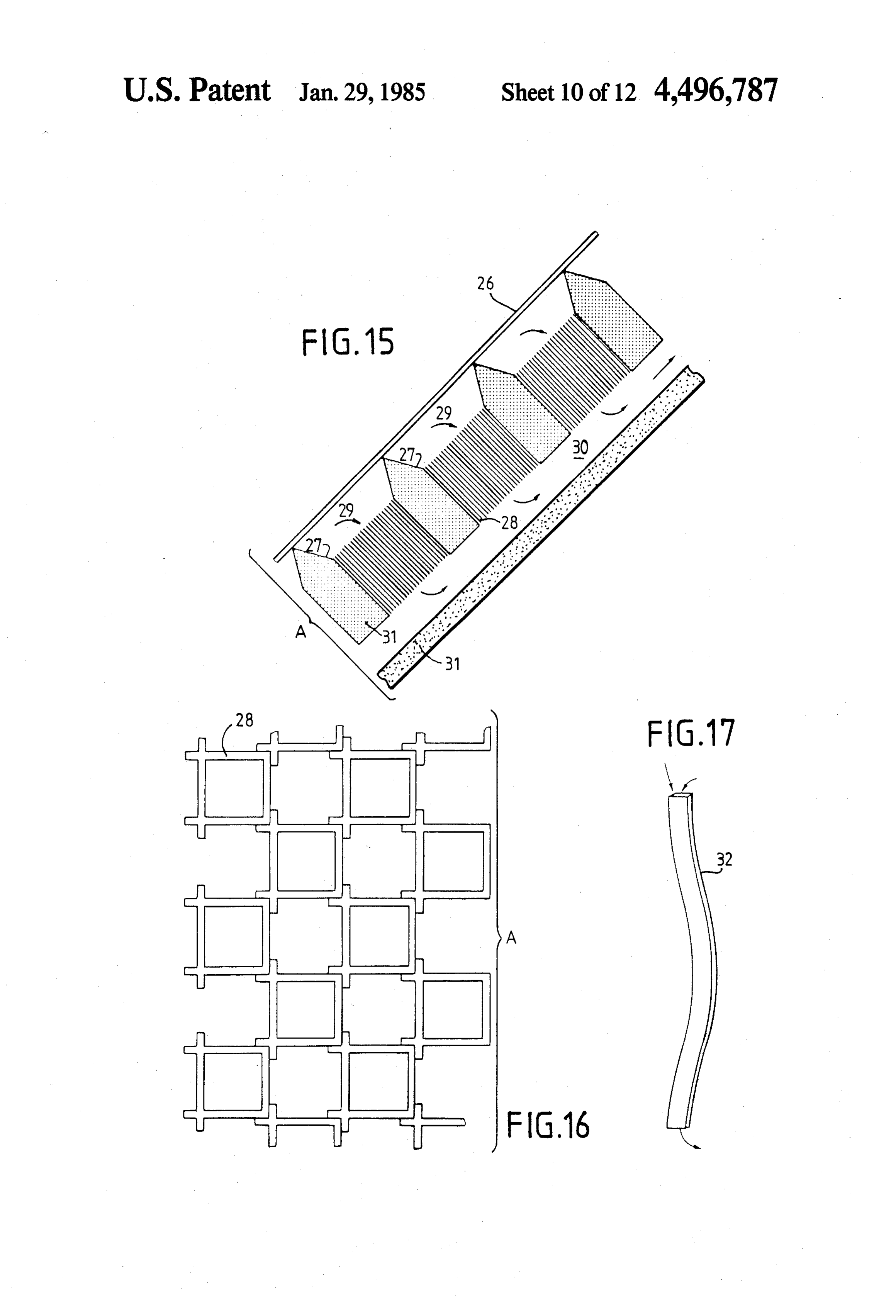
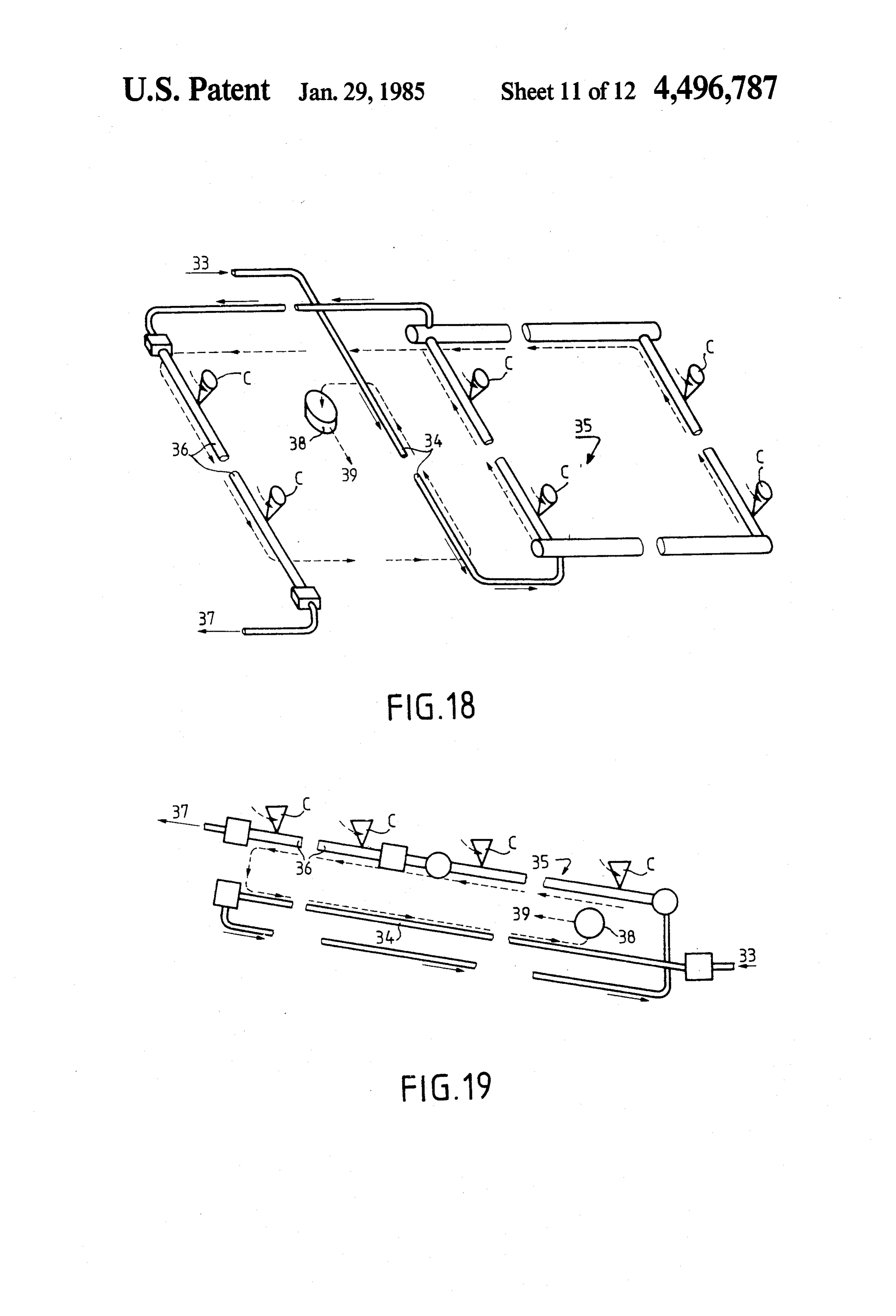
Other characteristics and advantages of this invention increasing energy losses through such opening (also will more clearly appear from the following description called second window), the first window being the inlet which is made in reference to the attached drawings in opening for solar radiation in the concentrator itself, which: which is to be closed. Such closing is effected by the FIG. 1 is a schematic elevational view illustrating an Fresnel lens 1. The dimensions of said first window are optical (dioptric) means for carrying out the method a priori arbitrary but they determine the dimensions of according to the invention; the whole of the cell and in particular of the framework FIG. 2 is a modified embodiment of such optical 10 containing and supporting all the pick up, conversion (catoptric) means; and thermal exchange elements as well as the accesso FIG. 3 is a schematic side view of an insolator for eS carrying out the invention; It will be easily understood that with the device just FIG. 4 is a schematic front view of such an insolator: described the radiation energy is converted into heat in FIGS. 5 to 8 are views illustrating four possible para 5 the "thermal focus' 3 and that it can also be transferred bolic generatrices used for realizing the optical means to the desired heat transfer fluid. According to the for carrying out the method of the invention; method of the invention the enclosure of said thermal FIGS. 9 to 11 are views illustrating generatrices of focus is brought to a negative pressure so as to circulate the reflective surfaces forming the "super-concentra air or any other gas admitted at 2A in the prefocus 2 tor' associated with the optical means according to the 20 and/or the remainder of the insolator (as will be seen invention; hereinafter) and admit it in pipes such as at 5. FIG. 12 is a schematic sectional view of such a super For safety purposes, there is also provided according concentrator adapted for a fixed thermal focus; to the invention among others a shielding device not FIG. 13 is a schematic sectional view of one embodi shown) situated on the radiation path either upstream of ment of a thermal focus for carrying out the invention, 25 the concentrator or at the outlet therefron. The control in case of an altazimuthal mount; system of such a device of a known type may use either FIG. 14 is a planar view corresponding to FIG. 13; optical or thermal waves or direct determination of the FIGS. 15 to 17 are schematic views illustrating absor orientation error.
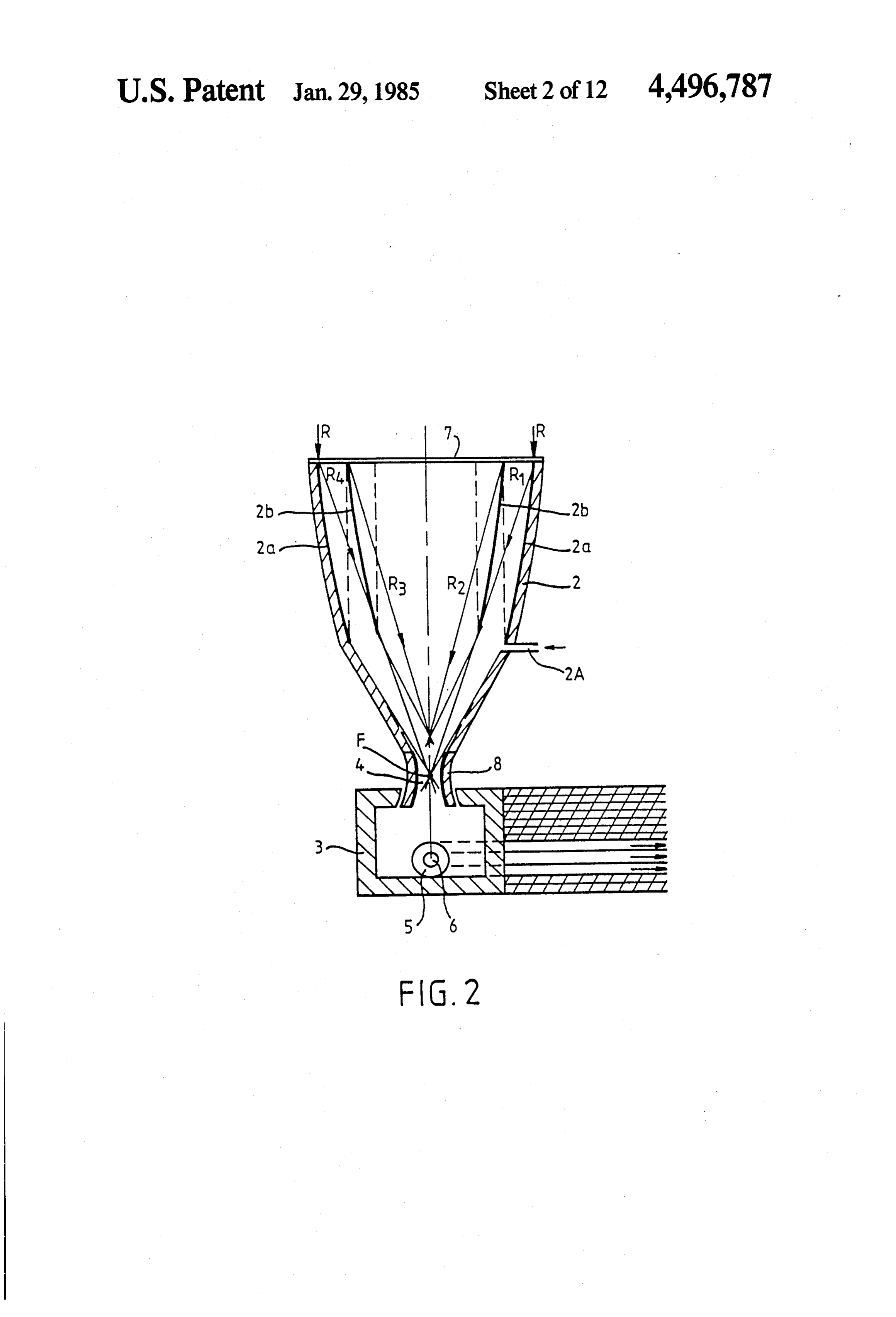
bent surfaces used for realizing an insolator for carrying With reference to FIG. 2, the prefocus 2 closed by out the invention without a concentrator; the transparent covering 7 comprises a wide-angled FIGS. 18 and 19 are schematic views to illustrate the multiparaboloid of revolution or reflective surface application of the invention for realizing thermal instal formed from several paraboloids (such as 2a-2b) inter lations; and nal relative to one another and explained in more detail FIG. 20 is the geometric illustration of the case of an hereinafter. The reflective parabola must necessarily be equatorial mount. 35 of a wide angle, i.e. using polar angles 6 greater than 90 DETAILED DESCRIPTION OF THE in order for the beam of reflected radiations (converg DRAWINGS ing beam R1, R2, R3, R4) to continue to propagate in the general direction of the incident light R, the thermal
With reference to the drawings, FIGS. 1 and 2 show focus being towards the ground and not in elevation as two modes of embodiment of an optical means for car would be the case if the polar angle of the paraboloid rying out the invention. reflector was less than 90. The selected position In the case of FIG. 1, the device consists of a Fresnel towards the ground for the thermal focus makes it possi lens 1 forming the inlet face of a thermally insulated ble to fix all the pipes for circulating the fluid to be enclosure 2 (called hereinafter "prefocus' containing heated. Thus, due to this fact, the invention permits the concentrator) made of an insulating refractory ma 45 safer realization and exploitation of these pipes in which terial which absorbs light radiation. This enclosure will high temperatures and pressures may reign; conse advantageously have the form of a volume of revolu quently, their thermal insulation is also realizable more tion (such as a cone or any other volume of revolution). easily, hence it can be of better quality, which is a very A conduit 2A is provided for admitting air or any significant aspect for attaining the purpose of this inven other suitable gas. tion, since the temperature of the heat transfer fluid(s) The incident parallel rays R coming from the sun necessarily results from a thermal balance, the loss ele after crossing the lens 1 converge at a point F called the ment of which must be reduced to the minimum, such "focal point'. The so concentrated light then penetrates reduction of the losses being precisely obtained by into a thermally insulated enclosure 3 called “thermal means of this invention.
focus' through an opening 4 of crosssection as small as 55 The wide-angled multiparaboloid reflector according possible, precisely formed at right angles with said focal to this invention is based on the following principle: point F. Said enclosure is crossed by fixed pipes for Let there be a generatrix of a wide-angle paraboloid circulation of heat transfer fluids (air-water) such as mirror, it being limited by two diameters, the high and 5-6. The optical means and its accessories described the low diameter. The light radiation directed so as to above, required to be capable of following the sun in its 60 pass through the low diameter must be stopped by an apparent diurnal motion, is designed so as to be neces other reflective paraboloid with the same focal point. sarily orientatable. To this end, the focal point F is Such other paraboloid also raises the same problems located according to the invention in principle at the and so on, which makes it necessary to consider several concurrent point of the rotational axes of the orientation paraboloids internal to one another. motion of said with its concentrator. It will be noted 65 The light rays close to the axis come directly into the that such orientation must be effected precisely (by focal opening or at least into the optical device situated means of devices not within the scope of this invention) near the focal opening. FIGS. 5 to 8 give representa for avoiding exaggerated increase in the dimensions of tions of several parabolic generatrices shown in full
Page 16
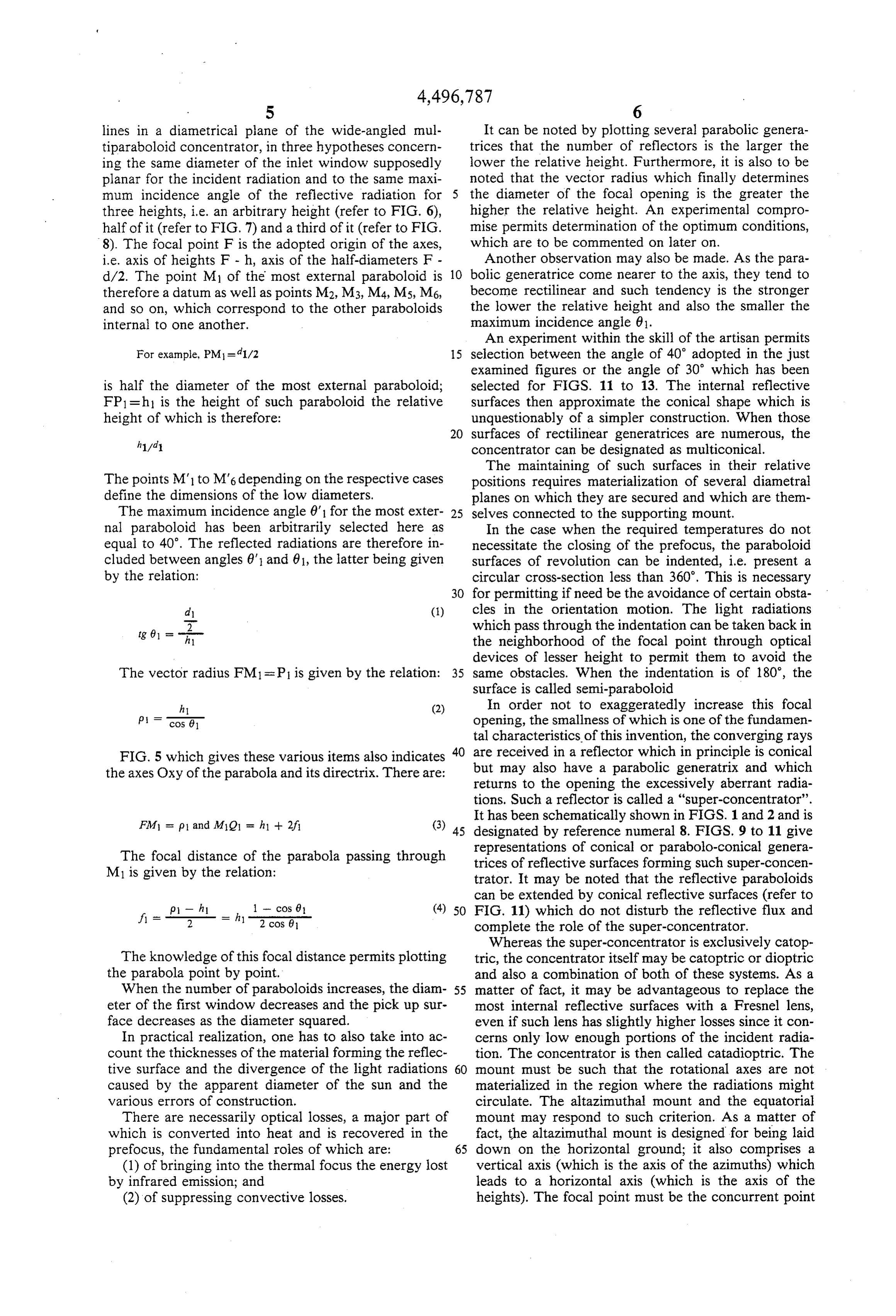
lines in a diametrical plane of the wide-angled mul It can be noted by plotting several parabolic genera tiparaboloid concentrator, in three hypotheses concern trices that the number of reflectors is the larger the ing the same diameter of the inlet window supposedly lower the relative height. Furthermore, it is also to be planar for the incident radiation and to the same maxi noted that the vector radius which finally determines mum incidence angle of the reflective radiation for the diameter of the focal opening is the greater the three heights, i.e. an arbitrary height (refer to FIG. 6), higher the relative height. An experimental compro half of it (refer to FIG. 7) and a third of it (refer to FIG. mise permits determination of the optimum conditions, 8). The focal point F is the adopted origin of the axes, which are to be commented on later on. i.e. axis of heights F - h, axis of the half-diameters F - Another observation may also be made. As the para d/2. The point M1 of the most external paraboloid is 10 bolic generatrice come nearer to the axis, they tend to therefore a datum as well as points M2, M3, M4, M5, M6, become rectilinear and such tendency is the stronger and so on, which correspond to the other paraboloids the lower the relative height and also the smaller the internal to one another. maximum incidence angle 61. An experiment within the skill of the artisan permits
For example, PM1 = 1/2 15 selection between the angle of 40' adopted in the just examined figures or the angle of 30 which has been is half the diameter of the most external paraboloid; selected for FIGS. 11 to 13. The internal reflective FP1 =h1 is the height of such paraboloid the relative surfaces then approximate the conical shape which is height of which is therefore: unquestionably of a simpler construction. When those 20 surfaces of rectilinear generatrices are numerous, the concentrator can be designated as multiconical.
The maintaining of such surfaces in their relative
The points M1 to M'6 depending on the respective cases positions requires materialization of several diametral define the dimensions of the low diameters. planes on which they are secured and which are them The maximum incidence angle 61 for the most exter 25 selves connected to the supporting mount. nal paraboloid has been arbitrarily selected here as In the case when the required temperatures do not equal to 40°. The reflected radiations are therefore in necessitate the closing of the prefocus, the paraboloid cluded between angles 6'1 and 61, the latter being given surfaces of revolution can be indented, i.e. present a by the relation: circular cross-section less than 360. This is necessary 30 for permitting if need be the avoidance of certain obsta di (1) cles in the orientation motion. The light radiations
which pass through the indentation can be taken back in the neighborhood of the focal point through optical devices of lesser height to permit them to avoid the
The vector radius FM1 = P1 is given by the relation: 35 same obstacles. When the indentation is of 180, the surface is called semi-paraboloid -- (2) In order not to exaggeratedly increase this focal p1 = ces 61 opening, the smallness of which is one of the fundamen tal characteristics of this invention, the converging rays
FIG. 5 which gives these various items also indicates 40 but are received in a reflector which in principle is conical the axes Oxy of the parabola and its directrix. There are: may also have a parabolic generatrix and which returns to the opening the excessively aberrant radia tions. Such a reflector is called a "super-concentrator'.
It has been schematically shown in FIGS. 1 and 2 and is (3) 45 designated by reference numeral 8. FIGS. 9 to 11 give
The focal distance of the parabola passing through trices representations of conical or parabolo-conical genera M1 is given by the relation: of reflective surfaces forming such super-concen trator. It may be noted that the reflective paraboloids can be extended by conical reflective surfaces (refer to
f =- - = hl 2 cos 6 (4) 50 FIG. 11) which do not disturb the reflective flux and complete the role of the super-concentrator.
Whereas the super-concentrator is exclusively catop
The knowledge of this focal distance permits plotting tric, the concentrator itself may be catoptric or dioptric the parabola point by point. and also a combination of both of these systems. As a When the number of paraboloids increases, the diam 55 matter of fact, it may be advantageous to replace the eter of the first window decreases and the pick up sur most internal reflective surfaces with a Fresnel lens, face decreases as the diameter squared. even if such lens has slightly higher losses since it con In practical realization, one has to also take into ac cerns only low enough portions of the incident radia count the thicknesses of the material forming the reflec tion. The concentrator is then called catadioptric. The tive surface and the divergence of the light radiations 60 mount must be such that the rotational axes are not caused by the apparent diameter of the sun and the materialized in the region where the radiations might various errors of construction. circulate. The altazimuthal mount and the equatorial There are necessarily optical losses, a major part of mount may respond to such criterion. As a matter of which is converted into heat and is recovered in the fact, the altazimuthal mount is designed for being laid prefocus, the fundamental roles of which are: 65 down on the horizontal ground; it also comprises a (1) of bringing into the thermal focus the energy lost vertical axis (which is the axis of the azimuths) which by infrared emission; and leads to a horizontal axis (which is the axis of the (2) of suppressing convective losses. heights). The focal point must be the concurrent point
Page 17
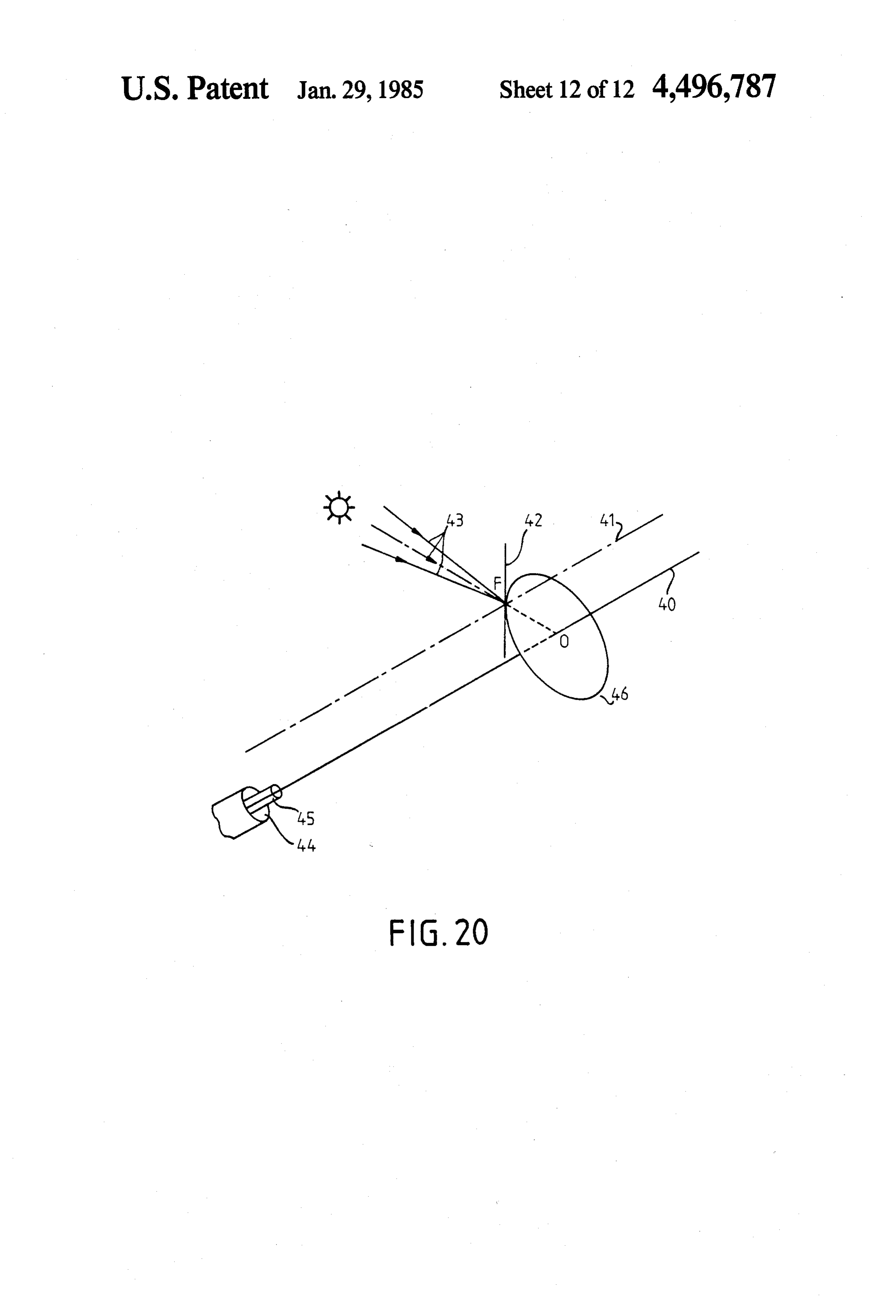
of the axes. It is indeed in this position of the focal point hand, the positions depend on those of the fluid pipes, that the divergent beam at the outlet of the focal open the design of which depends on various thermal consid ing sweeps in its motion the minimum space on follow erations. Two paths can be provided, i.e. an alignment ing the sun. This permits design of a less voluminous on the meridian, and an alignment according to the thermal focus, therefore having minimum loss surfaces East-West axis. In certain cases, in particular for equato but still achieving the desired purpose of the invention. rial regions, the transparent covering of the insolator As regards the equatorial mount (refer to FIG. 20) can be formed by an assembly of transparent domes which comprises an axis parallel to the axis of the world thereby reducing the volume of the intermediary space. (horary axis) and a perpendicular axis (declination axis), The thermal focus considered as the enclosure com the same observation applies for the focal point. How O prising the heat transfer fluid pipe is necessarily fixed, ever, in this case it is possible to avoid making the axes this being a characteristic of the invention and the per concurrent, the focal point being placed on the second formances reckoned on lying essentially on such fixity. axis or declination axis. The fixed portion of the thermal However, a movable element must provide the junction focus is then almost reduced to the pipes of heat transfer while preserving a suitable tightness between the mov fluid. 15 able prefocus which rotates about the axis of the heights Referring again to FIG. 20, reference 40 designates (or the axis taking the place thereof) and the fixed focus. the virtual horary axis, 41 the actual horary axis, 42 the Such junction part necessarily rotates with the axis of actual declination axis, 43 the convergent radiation azimuth (or the axis which also takes its place). Refer beam, 44 the cross-section of the cylindric air (or gas) ence is now made to FIGS. 12 to 14 where: pipe, 45 the tube for circulation of the heat transfer fluid 2 designates the wall of the prefocus; and 46 the maximum cross-section of the thermal focus. 8, the super-concentrator on the radiation inlet side of The horary axis can be materialized, e.g. through a the prefocus;
rotary cylinder of cross-section 46 in suitably located R represents the radiation outlet within the thermal bearings. Such an internally thermally insulated cylin focus;
der comprises on its outer surface in each focal point the 25 V designates the space reserved for the location of the declination axes which support the concentrators and thermal focus, and the junction element; about which the latter rotate. This cylinder constitutes 8a, the inlet cylinder rotating about the horizontal axis; the junction element referred to above; the fixed ele Ep, the vertical end position of the prefocus; ment is then formed only by the ends that must provide 8b, the sealing provided by various known means; for the tightness of the thermal focus. 30 9, the refractory (white) wall of the junction element of It is also to be noted that the insolator which is the the thermal focus;
container for the reception, absorption, and conversion 10, a junction part forming the upper portion of the elements and the like, must in principle have a transpar thermal focus;
ent covering inclined to the latitude of the location, 11, the thermal insulation;
facing South. This is the inclination corresponding the 35 12, a guide of motion about the vertical axis; minimum losses from reflections. This inclination, 13, the actual chamber of the thermal focus; called the "insolator setting', may deviate somewhat 14, the refractory walls;
from the latitude, thereby not resulting in large varia15, the circulating air;
16, the sealing provided by various known means;
tions in the optical losses, especially if there is used for the transparent covering an anti-reflective surface 40 17, the fixed portion of the thermal focus; which has moreover the advantage of avoiding the 18, the circulating air pipe;
external "blinking' that may be caused by certain posi 19, an insulation which only exists outside the chamber tions of the sun. The distribution of the concentrators in of the thermal focus;
the insolator can be made in two ways: 20, circulation of air in pipe 18; 1. By placing all altazimuthal mounts in the same 45 21, the tube of the heat transfer fluid, necessarily fixed; manner with respect to the transparent covering and 22, the upper face of the support or seating plane; spacing them out stepwise along the meridian; and 23, the bearings carried by the junction part 10; and 2. By inclining the altazimuthal mounts by the se 24, support arms of the concentrator fixed to the pin 25. lected setting angle and placing them always in the Realization of this structure does not present any same manner relative to the transparent covering. SO particular difficulties. Tightness (i.e., sealing) can al The vertical axis then becomes the perpendicular axis ways be provided if necessary by means of a supple, if with respect to the inclined plane. The rotation of the need be, pleated wall.
axes no longer reproduce the azimuths and the height of The pipe circulating the air which was heated in the the place of installation, but rather the azimuth and the thermal focus and in which possibly heat transfer fluid height of the sun at the point of the terrestrial globe 55 circulation tube(s) pass can be disposed in two ways: where the chosen inclined plane becomes the horizontal either in parallel to the meridian line which corre plane. The control of the motion is different but this sponds to the more logical circulation, since it permits belongs to the domain of the conventional regulation either the heated fluid to be degassed or possibly the problems. As to the equatorial mount, the distribution is produced vapor to be discharged, made by placing all the mounts in parallel in the same 60 or in parallel to the East-West line. For facilitating if manner relative to the transparent covering. need be in this case discharge of vapor, a slight inclina The kinematic devices to be provided for driving the tion, either East-West or reversed may be contem axes are devices known to the artisan. plated, the energy supplied by the lowest positions of For receiving at a given surface the maximum direct the sun on the horizon generally not being significant. radiation, the concentrators must be placed so as to be 65 Such inclination has moreover the advantage (espe as close to one another as possible, but however at a cially in case of insolators placed in the equatorial re sufficient distance apart so that they do not meet any gion) of facilitating the drainage of rainwater. The ad obstacles during their orientation motion. On the other vantage of this arrangement is to permit the use of rela
Page 18
tively long pipes which consequently collect more en the losses by infrared emission are low. The perfor ergy. As a matter of fact, if the meridian line were mance of this type of insolator, which may be manufac lengthened in order to obtain the same energetic result, tured relatively simply, is excellent so that the achieve the height of the North side framework would be pro ment of so-called "average temperatures' can be con hibitive. templated. The above-mentioned bumps may be merely Since air plays a very significant role in the system it constituted by lugs cut out from the very walls of the is suitable to supply, apart from the circulation blowers, channels, thereby permitting realization of short circuits filters for purification of air. which are used by the air streaks for more equal distri Reference will now be made to FIGS. 3 and 4 which bution thereof into the various channels. illustrate an insolator, comprising concentrators ac 10 The same alveola system can be used in the concen cording to the invention, in order to explain the opera trator either at the outlet of the prefocus in the focal tion thereof. Concentrators such as described above opening or in the thermal focus or simultaneously at the have been schematized and designated therein by the outlet of the prefocus and in the thermal focus. The general reference C. The particularity of such an insola losses through the focal opening are then significantly tor I (with its transparent covering T and its insulating 15 reduced.
and absorbing walls I) is that it comprises a very large The final purpose of the invention being the realiza intermediate space E1 where the prefocuses C are dis tion of industrial solar energy production, it is impor tributed as close as possible to one another in such a tant to obtain sufficiently high temperatures to permit way that the reception of the direct radiation R is as thermodynamic conversion and thus production of high as possible, measures being however taken for 20 electric energy under the best possible economical con preventing the orientation motions of such prefocuses, ditions. It is therefore suitable to examine more accu which moreover only move in parallel to one another rately the case of production of high pressure and high from being hampered. The volume which receives the temperature steam.
radiation not picked up by the concentrators is called The insolator with the concentrators can be consid the secondary focus. Conversion of the radiation into 25 ered as being formed of juxtaposed meridian slices or heat occurs as in any thermal insolator on the various East-West slices supplying vapor of the required char surfaces which receive the radiation and which must be acteristics, air or hot gas at a high temperature, finally treated so as to be absorbent and if possible not trans air or a hot gas or liquid at average and low tempera missive in the infrared. However, in the case of this tures. The assembly of the juxtaposed slices constitute a invention it is advantageous to carry such heat by means 30 thermal unit or steam boiler the dimensions of which of air or any other gas circulated in this secondary focus can be determined only by economical considerations. and admitted by any suitable means (not shown); such The feed water to such boilers must be preheated; the air or gas may indeed be heated to a higher temperature thermal unit must therefore comprise in the free space than that usually present in conventional insolators due provided within the insolator the equivalent of an econ to a specific mode of reception of the solar radiation and 35 omizer, the tubes of which being traveled by the feed of conversion into heat. Such air or gas which further water are heated by the air or hot gas carrying a portion more heats up little due to contact thereof with the of the main thermal flux which is the equivalent of various walls situated in the secondary focus, i.e. exter smoke in combustion type boilers. If there are other nal surfaces of the prefocus, of the mounts, of the main thermal fluxes they may be used to supply industries focus, of the pipes, and the like, is in fact introduced 40 which can be installed on the ground under the insola through aspiration into an alveolar structure A (refer to tor. FIGS. 18 and 19 illustrate several possible diagrams FIGS. 15 to 17) where 26 designates a transparent cov of installations. Thus, FIG. 18 is a schematic view illus ering; 27, internal reinforcing means with planar mir trating the case of the concentrators C aligned accord rors; 28, absorbent and anti-emissive alveolae for trans ing to the meridian inclined by the latitude whereas fer of heat to the circulating air; 29, the air inlet of the 45 FIG. 19 illustrates the case of concentrators C aligned secondary focus of the insolator; 30, the shaft for sup in the East-West direction with a slight slope. In the plying air or a hot gas, the outlet from said shaft increas drawings:
ing in the direction of circulation of the air; 31, the 33 designates the input of feed water; thermal insulation. The slightly curved channels 32 34, an economizer;
(refer to FIG. 17) receive the overall solar radiation 50 35, the vaporiation circuits;
which passes through the transparent covering of the 36, the over-heating circuits;
insolator and is partly reflected from the planar rein 37, the high pressure and high temperature steam outlet; forcing means according to Herteman-Touchais's 38, a blower; and
French patent application Ser. No. 75 07949 of Mar. 7, 39, return of air into the insolator. 1975. 55 A thermal station that can be contemplated according The walls of such channels are absorbent in the entire to the invention comprises moreover all accessories of range of the solar spectrum (visible and invisible); there the devices required for supplying vapor to the thermal fore they heat up and transfer the heat to the air or gas power station which must in particular supply electric circulating along the walls, such circulation being ren energy, i.e. heat transport collectors, separating bal dered turbulent by means of various bumps formed on 60 loons, automatic purgers, safety valves, various pipings said walls which are made of a very thin and very insu for feed, discharge, extraction, apparatus for production lating material, i.e. refractory glass, "Bakelite', and the of back up-water and treatment of such water, pumps, like. Such alveolae work from the point of view of blowers and the like, all this being within the domain of emission of infrared radiation, save for the distribution the artisan and not being specific to solar energy. As of the temperatures along the walls, a little like Francia's 65 regards the installations, specific to solar energy, the cellular structures. The circulation of the gaseous fluid random variability of the incident radiations requires occurs in the direction of propagation of the light and that regulation devices be provided to accommodate there are practically no losses through convection, and the produced energy so as to meet the consumption.
Page 19
Furthermore, it is suitable to recover all the energy Such a section can be polygonal and more particularly losses generally at a low temperature but which can be hexagonal. More generally, such surface the sections of upgraded in temperature precisely by means of the air which through the planes perpendicular to the optical insolators which are the object of this invention. This axis, are a priori indifferent can be formed to a certain upgrading can be effected either at a medium tempera extent of parabolic generatrices with or without the ture by means of the air insolator of high performance same focal point on the same axis or a parallel axis. The described hereinabove or at a higher temperature pre focal points corresponding to each generatrix can actu cisely by means of concentrators. The required ex ally be distributed in any manner on the radiation inlet changers can be housed in the intermediate space so as plane within the thermal focus. Such distribution of the to reduce thermal losses. The heat which can be up 10 focal points can be selected in particular so as to homog graded immediately may be stored temporarily, gener enize the illumination over the inlet plane or the receiv ally in perceptible form, in expectation of favorable ing surfaces located within the thermal focus itself. Sunshine. The storage containers are naturally placed In the first case, the device is particularly interesting under the insolator. for reinforcing the energetic illumination of photovol Although the regulation can be realized as is usual at 15 taic cells. In the second case, it is possible to more easily present by heat accumulation, the possibility of recover homogenize the temperatures within the thermal focus. ing the thermal losses however opens up the way to The cross-section of the radiation inlet window in the multiple applications in which a thermal source is neces thermal focus does not constitute a primary factor since sary. the near suppression of losses through such opening due The applications of the invention therefore include all to aspiration of the air, which recovers, on its passage in applications of fluid heating. the prefocus, the major portion of the re-emitted energy It is to be noted that all the above is applicable to the which is transformed into heat precisely in the focus, case when the reflective surface instead of being a pa makes the small size conditions less significant in the raboloid of revolution is cylindro-parabolic, the cross window.
sectional figures being exactly applicable to either case. 25 The rearward portion of the insolator forming the The multiple cylindro-parabolic concentrator has the thermal insulation can be locally transparent to illumi advantage of a higher energy pick up for the same nate if need be the ground or the premises located un width of the first window; it may have the disadvantage derneath. Such rearward portion, always thermally of a higher loss through infrared radiation passing insulated, can be formed of parallel transparent blades through the second window, the surface of which is a confining air streams or else alveolar structures of the little higher, still for the same width of the first window, Francia type with honeycombs, of transparent plastics but such losses are recovered by the prefocus which material or of supple plastics film pleated and depending constitutes a fundamental characteristic of this inven naturally.
tion. The light which thus crosses the pick-up assembly In particular, the following points can be specified: 35 either directly or by means of light guides may also be The transparent covering is in principle stationary, used for agronomic applications.
but, however, if it is desired to avoid the shadow of the There can be disposed in the intermediate space be frame supporting the transparent plate carried onto the tween the transparent covering and the rearward back concentrator the covering may be rendered movable. ground, apart from the already mentioned photother The transparent plate is generally rectangular; the 40 mal converters, photoelectric or photochemical con movement may then be reduced to a simple translation verters in the most favorable locations. The photoelec according to the smaller axis of the rectangle. tric cells being generally thin, their installation is there The transparent covering is generally planar but it fore facilitated. The electric energy thus obtained di may have a cylindric shape, i.e. a cylinder with or with rectly can provide energetic autonomy for the installa out a vertical axis and more generally an absolutely 45 tion or at least for the monitoring and safety devices. optional shape. It will be understood that this invention is only de In case all the concentrators cannot receive the direct scribed and represented in a purely explanatory and not radiation simultaneously, they can receive them at all limitative manner and that any useful modification through reflection from outer heliostats. The utilization can be brought thereto without departing from its of such heliostats may even be contemplated in the case Scope.
of the planar covering which is then selected preferably We claim:
as vertical. 1. A method of collecting and maximally utilizing The inlet window of incident radiation for the con Solar radiation, which comprises, in an intermediate centrator is not necessarily a planar surface of a circular Space between a transparent covering and an absorbent shape. In particular if it is: 55 receiving surface of an insolator, (a) a Fresnel lens, this window may have any shape, receiving collimated radiation coming from the sun in particular a polygonal one; it may be planar or consti through an optical means which is thermally insu tute a kind of dome on the prefocus; or lated and orientatable so as to track said radiation, (b) a multiparaboloid, this window can be a portion of converging such radiation to a focal point, a sphere to prevent diameter extension of the image spot 60 collecting through an opening having as small a diam on the focal plane. eter as possible the beam of radiation emanating The section of the optical system through a plane from said focal point, and making it penetrate into perpendicular to the optical axis may be absolutely a positionally fixed, thermally insulated enclosure, optional. In the case of the reflective surface, this may using the latter as a thermal focus containing fixed be formed of narrow elements of paraboloid of revolu 65 thermal exchange surfaces, tion having the same optical axis and the same focal bringing such enclosure to a negative pressure point, disposed close to one another to be able to pick thereby to cause air or another gas to flow there up more radiation than the usual circular shape permits. intC,
Page 20
receiving the solar radiation not previously absorbed means except for the portions that form the junction by thermal absorbent receiving surfaces while also between the fixed and movable portions. circulating air or another gas in said intermediate 10. A device according to claim 4, comprising supple Space, and mentary optical means called "super-concentrators' outputting the total incident energy transferred both 5 which are located in the neighborhood of the opening to said thermal focus and to said air or the gas situated at said focal point such as to embrace all of the circulating in the assembly of said insulator. convergent but possibly aberrant radiations to direct 2. A method according to claim 1, comprising dispos them efficiently towards the focal opening so that they ing said opening of small diameter substantially at right can penetrate into said thermal focus. angles to said focal point. O 11. A device according to claim 4, comprising supple 3. A method according to claim 1, comprising placing mentary alveolar absorbent receiving surfaces provided the concurrent point of the actual or virtual rotational either at the outlet from said optical means in the focal axes serving for the orientation motions of said optical opening or in said thermal focus or at either location so means substantially at said focal point. as to reduce the losses by re-mission through the focal 4. A device for collecting and maximally utilizing 15 opening.
Solar radiation comprising, in an intermediate space 12. A device according to claim 4, comprising, apart formed between a transparent covering and absorbent from the optical focusing means, receiving surfaces receiving surfaces of an insolator, an optical means consisting of tubular alveolae very absorbent in the which is thermally insulated and orientatable to track 20 visible and infrared ranges to form channels traveled in collimated radiation coming from the sun, said optical the direction of the radiation by circulating air having a means selected from the optical devices of the catoptric turbulent
motion.
device according to claim 4, comprising safety and dioptric type permitting propagation of a beam of shieling means disposed in the optical path of the radia reflected radiations in the general direction of incident tion.
light, a positionally fixed thermally insulated enclosure 14. A device according to claim 4, wherein the trans having negative pressures therein for causing air other parent gas to flow thereinto receiving the incident light, said trators covering may have of the insolator assembly with concen a translational motion.
insolator located in said insulated enclosure, a thermal 15. A device according to claim 14, wherein the focus in said intermediate space being a focal point of transparent covering may be planar or of different the optical path of the radiation with said intermediate 30 shapes and in that outer heliostats are provided when space having an opening of small diameter. the concentrators of the entire installation do not simul 5. A device according to claim 4, wherein the optical taneously receive the direct radiations. means comprises a Fresnel lens or reflective surfaces or 16. A device according to claim 15, wherein an inlet a combination thereof, the reflective factor of which is window of incident radiation to the optical focusing especially hight in the visible range and low in the infra- 3s means may be of a shape and cross-section, as may be red spectrum in association with a transparent covering the section of the optical means through a plane perpen located at the solar radiation inlet; said Fresnel lens dicular to the optical axis.
constituting such covering. 17. A device according to claim 4, wherein the rear 6. A device according to claim 4, wherein the optical portion of the insolator which forms thermal insulation means consists of a wide-angled multiparaboloid of 40 can be locally transparent to illuminate if need be the revolution or a reflective surface formed of several ground or the premises disposed underneath. wide-angled paraboloids of revolution located inside 18. A device according to claim 4, comprising con one another, such paraboloids being indentable over an verters other than photothermal converters including angle that reaches 180". photoelectric converters disposed at any available place 7. A device according to claim 4, wherein the optical 45 so as to best use the incident energy. means consists of wide-angled multisurface cylindro 19. A device according to claim 4 for the realization parabolic elements. of solar energy cells wherein in the intermediary space 8. A device according to claim 4, wherein the ther included between the transparent covering and the mally insulated enclosure designed fon serving as the absorbent surfaces one or more of said optical means or thermal focus is traversed by fixed pipes for circulation 50 concentrators is disposed in one or more lines in both of a heat transfer fluid. directions in space along East-West or North-South 9. A device according to claim 4, wherein said ther lines.
mal focus is stationary with respect to said optical : k s: sk k
Provenance
- Collection
- Cited prior art
- Original PDF
- patentimages.storage.googleapis.com →
- Filed
- 1982-12-16
- Pages
- 20
- Method
- pdftotext (the PDF's own text layer) + pdftoppm 300dpi page scans
- Source
- Google Patents bibliographic record
- Granted
- 1985-01-29
- Inventors
- Maurice Touchais; Madeleine Djelalian
- Transcribed from
- patentimages.storage.googleapis.com →