patent · US1993213
Solar ray apparatus
5 March 1935
Page 1
Drawing sheet — no readable text.
Page 2
Patented Mar. 5, 1935
UNITED STATES PATENT OFFICE 1993,213
soLAR RAY APPARATUS
Ferdinand A. Gill, Chicago, Ill.
Application October 18, 1933, serial No. 694,051
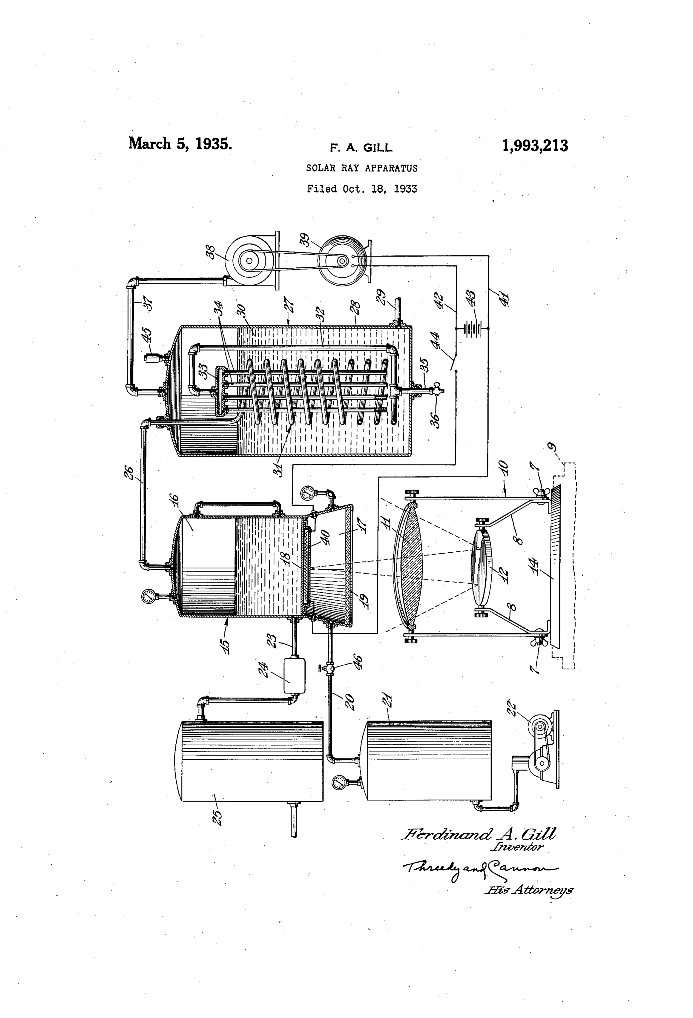
This invention relates to solar ray apparatuses. 16 of the vapor generator unit 15 is a fluid inlet It is an object of this invention to provide an 23 which leads, through an automatic cut-off improved solar ray apparatus which is relatively valve 24 of conventional design, to a fluid Stor Simple and inexpensive in construction and ef age tank. 25. The fluid storage tank 25 in turn 5 ficient in use. communicates with a suitable source of fluid un Other objects of the invention are: to provide der pressure such, for example, as a municipal an improved vapor generator for converting the water supply.
energy of the collected solar rays into energy in Leading from the boiler compartment 16 of the the form of vapor or steam pressure; and to pro vapor generator unit 15 is a conduit 26 which . vide the combination hereinafter described and leads into a second vapor pressure generator 0. claimed. unit 27. This auxiliary vapor generator unit 27 Other objects will appear hereinafter. comprises a boiler 28, which may be of any de The invention consists in the novel combina sired design and shape. This boiler 28 has an tion and arrangement of parts to be hereinafter inlet 29 through which a suitable fluid such, for 5 described and claimed. example, as water may be introduced, and is also 5 The invention will be best understood by ref provided with a safety valve 45. erence to the accompanying drawing, showing Arranged in the vapor generator or boiler 28 the preferred form of construction and in which: and surrounded by the fluid 30 is a coiled tube
The single figure, partly in section and partly 31, the uppermost convolution of which communi in elevation, shows a preferred form of the new cates with the conduit 26 and the lowermost con 20 apparatus and therein a solar ray collecting and volution of which opens into a vertical pipe Or. reflecting device is generally indicated at 10. This conduit 32 which is arranged within the boiler Solar ray collecting and reflecting device 10 com 23. This conduit 32 opens at its upper end into
prises a Suitable convex ray collecting lens 11 and a distributor head 33. Extending from the dis a Suitable ray reflector 12, both carried by a base. tributor head 33 through the coil 31 is a Series. 25 14 adjustable or rotatable in a horizontal plane of parallel injector tubes 34 which open at their upon a support 9 so as to accommodate the lens lower ends into the fluid 30 in the boiler 28; a ll and the reflector 12 to the declination of the condentate drain 35 leading from the lowermost Sun and the various angles at which the sun's coinvolution of the coil 31 out of the boiler 28. rays Strike the ray-collecting lens 11. Further This drain 35 is controlled by a valve 36 which 30 to affect the adjustment of the lens 11 and re is arranged externally of the boiler 28. flector 12, the reflector 12 is mounted on a bracket A conduit 37 leads from the top of the boiler 8 which is carried by, and which is stationary 28 to a conventional prime mover which may 3 5 relative to, the base 14 while the lens 11 is ad bg a fluid pressure operated turbine 38. This justably mounted upon the frame 13 which in prime mover 38 may be utilized in any manner turn is pivotally mounted upon the bracket 8, as to do work as by operating an electric generator at 7, for movement in a vertical plane. 39 of conventional design.
Arranged above the solar ray collecting device Arranged in the compressed air compartment 40 10 and Supported in any suitable manner is a 17 and suitably electrically insulated therein is 40 an electric heating element 40 which is elec vapor pressure generator unit which is generally trically indicated at 15. This vapor generator unit 15 connected to the generator 39 by way of Comprises a boiler compartment 16 and a com conductors 41 and 42; a storage battery or ac pressed air compartment 17, these compartments cumulator 43 being electrically connected to the being Separated by a flexible heat-conductive di generator 39 and to the heating element 40 and aphragm or wall 18 which is preferably in: the conductors 42. 44 being arranged in one of the 45 a control switch form of a sheet of flexible copper, this being the preferred metal because of its high heat conduc Operation tive capacity. A transparent wall 19, preferably The Solar rays collected by the lens 11 are di 50 made of quartz, forms the bottom of the com pressed air compartment 17; this wall 19 being rected by the reflector. 12 through the transpar ent Wall 19 of the vapor generating unit 15 and positioned to have the solar rays reflected from thence against the flexible metal bottom Wall or the reflector 12 directed therethrough.
Communicating with the compressed air com diaphragm 18 of the boiler compartment 16 thereby heating the fluid in the compartment 16 55 partment 17 of the vapor generator unit 15 is to a conduit 20 which leads to a compressed air derconvert the same into vapor. This vapor un 55 the pressure caused by its own accumulation accumulator or pressure storage tank 21 that has in the boiler compartment 16 passes through the associated therewith an air compressor 22 of con conduit 26 into the coil 31 through which it ventional design. circulates thereby heating the water or other 80 Communicating with the boiler cómpartment fluid 30 in the boiler 28 of the auxiliary generator 60
Page 3
27. After passing from the coil 3, the steam It has been found by experiment that the pre or other heated vapor enters the conduit 32, ferred ratio between the cubic volumes of the passes into the distributor 33, and thence into boiler compartment 16 and the boiler 28 is ap the injector tubes 34 from which it is ejected into proximately 1 to 10 and that the preferred cubic the fluid 30 and to convert the same into a vapor. volume of the boiler compartment 16 is about 1. The vapor formed in the auxiliary vapor gen gallon since the volume of Water can readily be erator 28 passes through the conduit 37 to the heated by the Sun's rays collected and reflected turbine or other prime mover 38 which operates as set forth. However, the boiler 28 may be made the generator 39. Part or all of the electric en larger and two or more coils 31 and associated 10 ergy output of the generator 39 may be utilized parts be placed therein, which necessitates a like 10 in any desired manner but a part, at least, of number of vapor generating units 15. the output of the generator 39 is preferably di The flexible metal wall or diaphragm 18 may, rected to the storage battery or accumulator 43 if desired, be coated with any Suitable heat-con from which it may be drawn, as desired, by cloS ductive Substance to increase the heat-conduc 5 ing the Switch 44, to heat the electric heating tive or transferring properties of the diaphragm. 15 element 40 so as to continue the operation of The air pressure in the compartment 17 must the apparatus when the solar rays are not avail be regulated to correspond with pressure able as at night and on cloudy days. changes, in the boiler compartment 16. This Some of the Stean or other vapor passing may be accomplished by conventional automatic 20 through the coil 31 will be condensed before control devices now in the market or it may be 20 passing into the conduit 32 and this condensate done manually as, for example, by manipulat may be drained from the coil 31 as desired by ing the valve 46 which is arranged between the opening the drain valve 36. compressed air tank 21 and the boiler compart It willi be noted that in the present apparatus ment 17.
25 the reflected solar rays do not directly strike the It is to be noted that the fiexible, heat-conduc bottom Wall 18 of the vapor generator or boiler tive copper metal diaphragm 18 is necessitated 15 but first pass through the transparent quartz by the fact that a rigid, relatively heavy or thick wall. 19 which forms the bottom of the con metal plate cannot be used for the bottom of the pressed air compartment 17. In addition to boiler compartment 16 since it would not have 30 functioning as the botton waii of the com the requisite high heat conductive property of 30 pressed air compartment 17 the transparent the copper sheet readily to transfer heat from quartz wall 19 also cooperates with the lens 11 the compressed air compartment 17 to the boil and reflector 12 as a part of the Solar ray-col er compartment 16.
lecting and reflecting apparatus to focus the col
While I have illustrated and described the 35 lected rays upon the heat-conductive flexible preferred form of construction for carrying my copper diaphragm 18 which, because of its high invention into effect, this is capable of variation heat-conductive property, readily transfers its and modification, without departing from the heat to the water in the boiler compartment 16 spirit of the invention. I, therefore, do not wish to generate vapor therein. to be limited to the precise details of construc 40 As the vapor pressure in the boiler compart tion set forth, but desire to avail myself of such ment 16 of the vapor generator 15 increases the Variations and modifications as come within the flexible metal bottom or diaphragm 18 yields Scope of the appended claims.
slightly and flexes downwardly, thereby slightly Having thus described my invention what I enlarging the cubic volume of the vapor genera claim as new and desire to protect by Letters tor compartment or boiler 16. This vapor pres Patent is: 45 sure on the flexible diaphragm 18 is, however, 1. A vapor generating unit, comprising: a offset or neutralized by the pressure of the com- . housing including a boiler compartment and a pressed air in the compartment 17. This ar compressed air compartment; a heat conduc rangement is made necessary because of the fact tive flexible diaphragm arranged between and 50 50 that while the side walls and top of the boiler Separating said compartments; and means for compartment 16 are made of relatively heavy introducing air under pressure into said com boiler plate metal which is capable of resisting pressed air compartment.
the maximum vapor pressure allowable in the 2. A vapor generating unit, comprising: a boiler compartment 16, the bottom wall of the housing including a boiler compartment and a 55 boiler compartment 16, being made of a rela compressed air compartment; a heat conductive SS tively thin, flexible metal diaphragm 18 is in flexible diaphragm arranged, between and Sepa capable, by itself, of resisting the vapor pressure rating said compartments; said compressed air in the boiler compartment 16 and must have an compartment having a transparent bottom wall external, resilent support on its bottom side. adapted to be arranged in the path of Solar 60 The compressed air in the compartment admir rays; and means for introducing air under pres- 60 ably provides this external support for the metal sure into said compressed air compartment. diaphragm 18 and when once heated retains its FERDNAND A. GILL. heat for a considerable length of time.
Provenance
- Collection
- Cited prior art
- Original PDF
- patentimages.storage.googleapis.com →
- Filed
- 1933-10-18
- Pages
- 3
- Method
- pdftotext (the PDF's own text layer) + pdftoppm 300dpi page scans
- Source
- Google Patents bibliographic record
- Granted
- 1935-03-05
- Inventors
- Ferdinand A Gill
- Transcribed from
- patentimages.storage.googleapis.com →