patent · US2273202
Engine
17 February 1942
Page 1
Drawing sheet — no readable text.
Page 2
Drawing sheet — no readable text.
Page 3
Patented Feb. 17, 1942 2,273,202
UNITED STATES PATENT office
ENGINE
Thomas Jackson, Kokomo, Ind., assignor to Con tinental Motors Corporation, Detroit, Mich., a corporation of Virginia
Application May 15, 1940, serial No. 335,361
My invention relates to engines and more par Supply lubricating oil to engine bearing parts and permitting the excess lubricating oil supplied ticularly to engines of the crankcase compres thereto to be subsequently discharged into the sion two-stroke cycle type.
In engines of the type aforesaid, much diffi 5 : engine crankcase where same intermingles with the fuel mixture in said crankcase to lubricate .
culty is experienced in the proper lubrication other moving parts of the engine and to be sub of engine parts due primarily to the absence Sequently carried along with the fuel to the en of proper control means for regulating the gine combustion chamber where same is burned amount of lubricating oil which is supplied to the along with the fuel in the usual manner. engine. It is customary to mix lubricating oil 10 A still further object of my present invention with the fuel in the fuel tank and depend on the is to provide an improved two-stroke cycle en fuel carrying an adequate amount of lubricating gine of the crankcase compression type by pro oil into the crankcase where same is atomized, viding separate fuel and lubricating oil supply resulting in the lubricating oil being forced intomeans and including manually adjusted control the engine bearings and other parts to be lubri 5 devices for metering the amount of fuel and lu cated when the charge of fuel and oil in the bricating oil supplied to said engine crankcase. crankcase is compressed. The above method is A still further object of my invention is to not always satisfactory because the operator improve engine performance by providing a sep sometimes becomes careless and does not provide the proper amount of lubricating oil in the fuel 20 arate engine means for supplying lubricating pil to the parts to be lubricated by reason of the tank and as a result the engine parts to be lubri suction pressure produced in the closed engine cated do not receive an adequate supply of lubri cating oil. Furthermore, this customary method crankcase chamber.
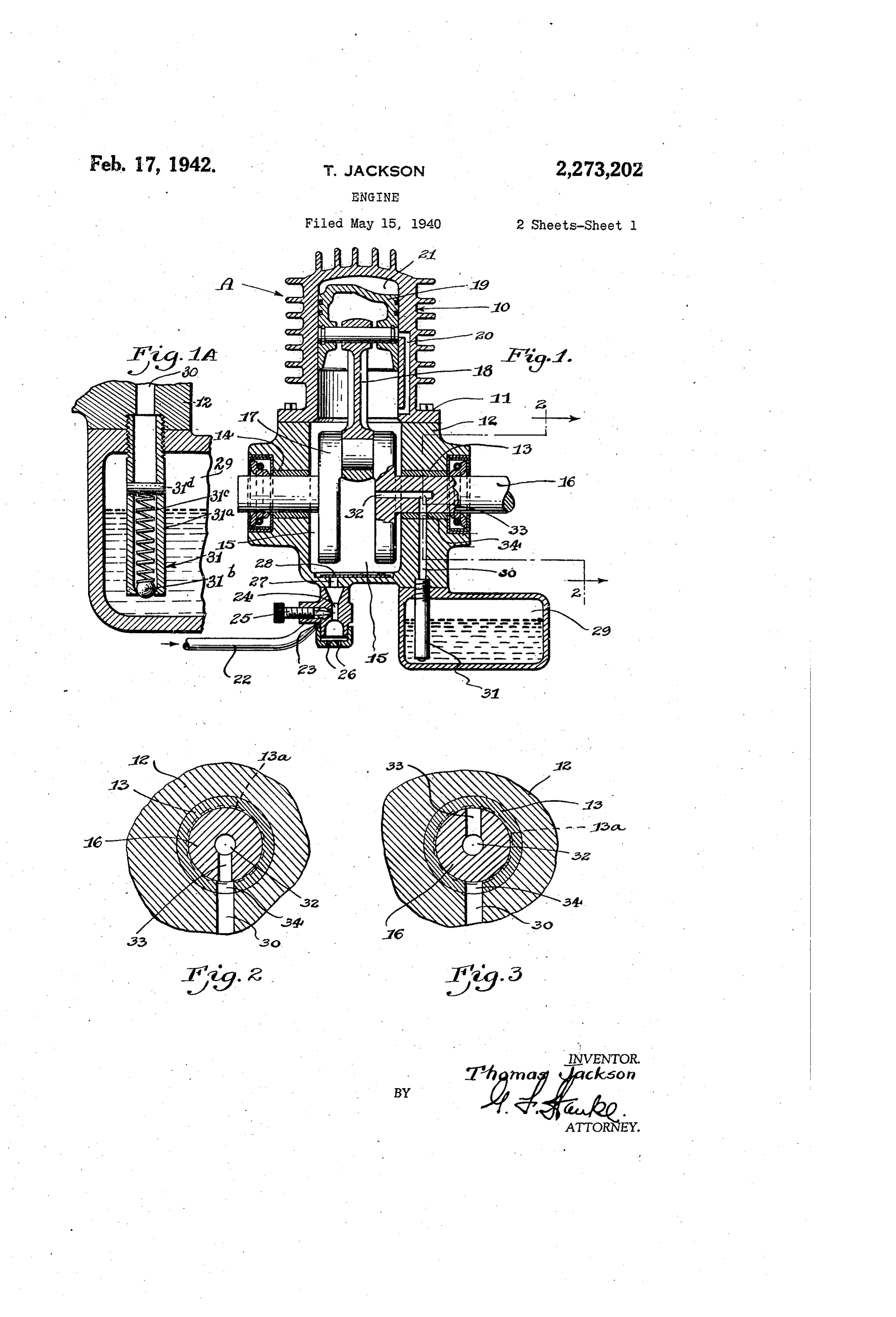
For a more detailed understanding of my in of lubricating the bearing parts of a two cycle vention, reference may be had to the accompany engine results in an excessive consumption of 25 ing drawings illustrating a preferred embodiment lubricating oil as it is the practice to provide a of my invention in which like parts are referred large excess of lubricating oil in order to make to by like characters throughout the Several views, sure that the lubricating oil is uniformly distrib and in which:
uted throughout the fuel mixture charge so as Fig. 1 is a vertical longitudinal sectional view to provide lubrication for any of the engine parts through a two-stroke cycle internal combustion coming in contact with the said charge. 30
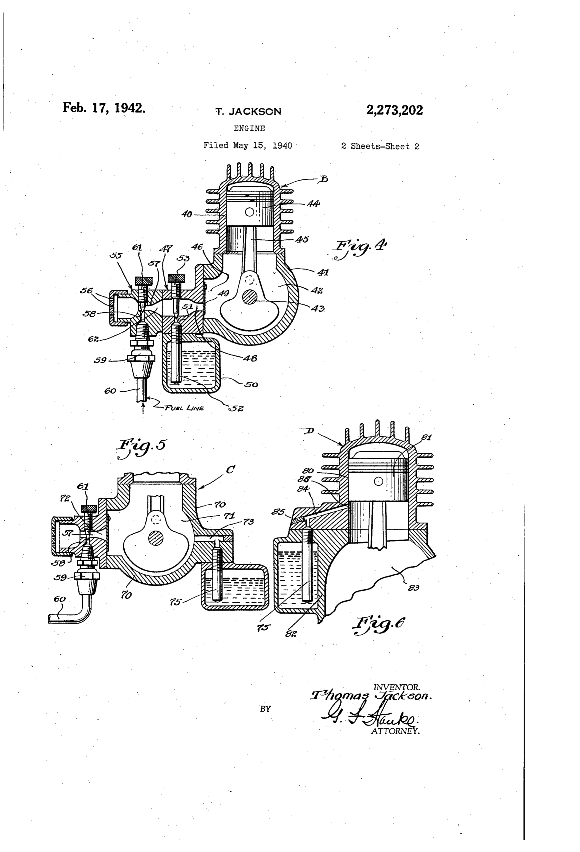
An object of my present invention is to elimi engine of the crankcase compression type and which embodies, my invention, nate the above mentioned, difficulties in connec Fig. 1A is a detail sectional view of the check. tion with the operation of a two-stroke cycle valve, engine of the crankcase compression type by pro viding a construction for separately introducing 3: lineFig.2-22 is a detail sectional view taken on the of Fig. 1, fuel and lubricating oil to the engine. Fig. 3 is a detail sectional view similar to Fig. Another object of the present invention is to 2 and showing another position, construct an engine of the type aforesaid which Fig. 4 is a detail sectional view of a modified can be more economically and efficiently operat 40 engine . ed by providing a separate means for introducing lubricating oil to the engine parts or bearings of Fig. 5construction, is a detail fragmentary sectional view to be lubricated in such a way as to obtain a a modified construction, and minimum uniform consumption of lubricating oil Fig. 6 is a detail fragmentary sectional view without the danger of bearing failure due to the of a still further modified construction. lack of an adequate supply, of lubricating oil. Referring more particularly to Figs. 1 and 2, A further object of my present invention is my improved engine structure is designated as to construct an improved engine of the type a whole by reference character “A” and com aforesaid by providing an independent lubri prises a cylinder O bolted or otherwise secured as at to a crankcase structure 2. The crank cating oil supply means for introducing lubri case structure carries crankshaft bearings 3 cating oil directly to engine bearings and/or other and 4 and defines a closed crankcase chamber parts thereof
A still to beobject further lubricated.
of the present invention 5. A crankshaft is is rotatably supported by is to construct animproved two-stroke cycle en these crankshaft bearings 3 and f4 and is pro gine and of thelubricating type aforesaid vided with the crank 7 to which is pivoted the
providing separate operable to 55 conventional connecting rod 8 connecting the
Page 4
piston 9 to the crankshaft. The cylinder cylinder 40 and a crankcase 4 providing a closed is provided with the usual by-pass 20 for, con crankcase chamber 42 in which a fuel mixture ducting the compressed fuel mixture from the is introduced, compressed and then transferred closed crankcase cylinder 2. to the interior of this engine to the engine combustion chamber in the usual . My improved engine construction comprises which way. The crankcase supports a crankshaft 43 separate fuel and lubricating oil supply means. connecting is connected with piston 44 by the usual
The fuel line 22 leading from the fuel tank is The crankcase is provided with a port 46 and connected with the carburetor inlet 23, which secured to the crankcase is a unitary lubricating carburetor is provided with the usual venturi 24 0 oil supply means 47 carrying a passage 48 open and a manually adjustable needle valve 25, the ing into the crankcase chamber 42 and having air being admitted through suitable ports 26 in the carburetor unit. The above described fuel associated therewith a check valve 49. The lu mixture and forming device connects with a pas bricating oil supply means includes an oil cham ber or reservoir 50 and an oil duct 5 opening sage 2 in the crankcase wall and has associated 5 into the passage 48. A check valve 52 is prefer therewith a conventional check valve 28 which ably associated with the oil duct 5 and said is operable to allow free flow of the air and fuel structure preferably further supports a manually mixture into the crankcase under suction pres adjustable needle valve 53 which is Operable to sure in said crankcase chamber but which closes passage 27 during compression within Said closed 20 control the discharge of the lubricating oil into the passage 8 from the oil duct 5.
Crankcase.
A suitable oil tank or reservoir 29 is bolted or The needle valves permit ready manual ad otherwise secured to the engine crankcase stric justment of the fuel and oil discharge Openings, ture and connects with a passage 30 in said varied but obviously the flow of fuel and oil may be crankcase which has associated therewith a coni by selectively varying the size of said dis charge openings.
ventional type check valve 3. More particularly 25 A carburetion device or structure 55 is prefer this check valve comprises a pipe section 3 a.
peened over at one end to support a ball Stb ably secured to the lubricating oil supply means which is urged toward its seat by a suitable light 47 and is provided with a conventional air inlet 5, carburetor venturi 4 and fuel inlet 58 con spring 3 ?c, the spring being seated against a pin 30 nected by a coupling 59 with a fuel Supply line or other suitable abutment 3d. The crankcase B. A manually adjustable needle valve 6 f is is provided with a passage 32 extending longi preferably supported by the carburetor casing tudinally of the crankshaft which communicates at all times with a radial passage 33 aligned in toItcontrol the outlet of fuel passage 58. will be thus observed that as the carbu the plane of the passage 8. The bearing f is preferably provided with an annular spiral oil 35 reted fuel flows through the primary conducting portion 2, through passage 48 and into the groove 3a and with a port 3 which iregisters with crankcase chamber 42 in response to suction passage 30 and these passages 3D and 3 cos operate to periodically be moved into registra pressure within said crankcase chamber, that tion on rotation of the crankshaft so as to in 40 lubricating oil will be picked up by the fuel termittently supply lubricating oil to bearing stream and taken into the crankcase where same 3 and to the interior of the crankcase. It will is caused to flow to the various engine parts to be noted that the passage 3 is constructed and be lubricated in the usual manner. timed with relation to crankshaft rotation so as ^ In Fig. 5 the crankcase of engine C is con to register with passage 30 when suction pressure structed to provide a closed chamber f. The is introduced in said crankcase so as to induce 45 ilarcarbureted fuel is admitted at 72 by means sim the flow of lubricating oil through said passages oil istointroduced that shown in Fig. 4, and the lubricating directly into the crankcase from in response to suction pressure in the engine closed crankcase. The diameter or size of these an oil duct 73 which is openly connected to the passages 30, 32 and 33 may be varied as desired crankcase so as to subject the oil supply to the for varying the amount of lubricating oil which 50 suction pressure in the crankcase, and prefer is permitted to flow therethrough. ably a conventional ball check valve 75 is con stricted to meter the incoming oil. Also the
It will thus be noted that the crankshaft bear size ing 8 is supplied directly with a measured of the oil discharge duct may be preferably amount of lubricating oil and excess lubricating 55 selected so as to only feed the right amount of lubricating oil into the crankcase chamber in oil is subsequently discharged into the crankcase chamber 7. The above described construction response to the suction pressure therein. insures positive lubrication of the main crank which In Fig. 6, the engine D has a cylinder 80 in shaft bearing and the adequate supply of lubri piston f is operable, and a crankcase 82 cating oil to the crankcase at all times for all 50 providing a closed crankcase chamber 83. The other parts of the engine to be lubricated. It oil supply line 4 is connected to the cylinder as will be observed that under all conditions of at 5 and the oil discharge opening 86 is arranged engine operation, we are assured of a correct to be uncovered by the piston skirt at or near supply of carbureted fuel and lubricating oil the end of the suction stroke to place the oil sup whereby to insure satisfactory engine operation s ply in open communication with the suction at all times. Furthermore, the above construc pressure in Said closed crankcase chamber. This tion results in a minimum consumption of lubri provides a construction which separately admits cating oil and provides for economical engine oil to the crankcase chamber where same inter operation with a minimum of maintenance costs. mingles with the fuel mixture therein and is con If desired lubricating oil may be directly con it. to various parts of the engine to be lubri Catec ducted from passage or conduit to other en- '
In both of these constructions, as described gine parts to be lubricated, the excess oil being above, allowed to pass into the crankcase where the oil it will be observed that I have provided can be used to lubricate other moving, parts. means for separately supplying fuel and lubri Referring to Fig. 4, the engine B includes a Cating oil to the engine in response to suction 75 pressure in the crankcase and this means is
Page 5
operable to insure at all times an adequate and cooperating passages connecting same with measured supply of lubricating oil for lubricating the crankshaft bearing and crankcase interior, the engine bearings and other parts of the en Said passages formed in the crankcase wall and gine and thus obtain efficient lubrication with a crankshaft respectively and so constructed and minimum of oil consumption. The operation of 5 arranged as to periodically place said oil reservoir an engine constructed in accordance with my in in communication with the crankcase interior whereby to periodically cause the lubricating oil vention may be economically operated and is ab solutely free from lubricating difficulties, thus in to 6.flew to said crankshaft bearing. In a crankcase compression two-stroke cycle suring continuous and reliable engine operation with a minimum of time lost for maintenance 0. engine, a closed crankcase, a crankshaft rotata and servicing. ble therein, a crankshaft bearing, means supply Although I have described some of the pre ing a carbureted mixture of fuel and air to said ferred constructions of my invention, it will be crankcase, and separate means for introducing a apparent to those skilled in the art to which my lubricating oil to the crankshaft bearing and invention pertains, that various modifications 15 crankcase and including an oil reservoir exterior and changes may be made therein without de ly of said crankcase and connecting passages parting from the spirit of my invention or from formed in said crankshaft and crankcase re the scope of the appended claims. spectively cooperating to cause an intermittent I claim: flow of lubricating oil to said crankshaft bearing 1. In an internal combustion engine of the 20 from said oil reservoir, said lubricating oil in two-stroke cycle type, a closed crankcase, a excess of that used by the crankshaft bearing crankshaft rotatable therein, an engine bearing, being 7.
introduced into the crankcase.
In a crankcase compression two-stroke cy means for supplying a vaporized mixture of fuel cle engine, a closed crankcase, a crankshaft ro and air to said crankcase, and separate means tatable therein, a crankshaft bearing, means Sup for supplying a lubricant to the engine bearing 25 plying a carbureted mixture of fuel and air to from a source of supply exteriorly of the engine said crankcase, and separate means for intro crankcase, said fuel mixture and iubricant supply ducing a lubricating oil to the crankshaft bear means operable in response to suction pressure ing and crankcase and including passages formed within the crankcase. 30 in said crankshaft and crankcase respectively 2. In an internal combustion engine of the two cooperating to cause an intermittent flow of stroke cycle type, a closed crankcase, a crank lubricating oil direct to said crankshaft bear shaft rotatable therein, an engine bearing, means ing and constructed and arranged to subsequent for supplying a vaporized mixture of fuel and air ly conduct excess lubricating oil from said crank to said crankcase in which same is compressed 35. shaft bearing to said crankcase. 8. In a crankcase compression two-stroke cy and subsequently introduced into the engine cle engine having a cylinder and a piston oper cylinder and means supplying a measured amount of lubricating oil to said engine bearing able therein, a closed crankcase chamber, a from a source of supply exteriorly of the engine crankshaft rotatable therein, means supplying a crankcase carbureted mixture of fuel and air to said crank and in an amount in excess of the 40 case, quantity to be used for lubricating the engine and separate means for introducing a lubri bearing, said Surplus lubricating of being subse cating oil to the carbureted mixture of fuel and quently discharged into the crankcase and there air in said crankcase chamber only during the - by mixed with the fuel mixture. time said crankcase is being subjected to Suc 3. In an internal combustion engine of the 45 tion pressure by reason of the travel of the pis two-stroke cycle type, a closed crankcase, & ton outwardly of the engine cylinder. crankshaft rotatable therein, an engine bearing, 9. In a crankcase compression two-stroke cy means for supplying a vaporized mixture of fuel cle engine, a closed crankcase, a crankshaft ro and air, to said crankcase in which same is con tatable therein, a crankshaft bearing, an air pressed and subsequently introduced into the 50 passage connected with said crankcase, a check engine cylinder, and separate means operable in waive associated with Said air paSSage, means response to Suction pressure in the crankcase for . supplying a carbureted fuel to said air passage, Supplying a measured amount of lubricating oil and lubricating oil inlet means intermediate Said to said engine bearing from a source supply ex fuel inlet and said check valve. teriorly of the engine crankcase. 55 10. In a crankcase compression two-stroke cy 4. In an internal, combustion engine of the cle engine, a closed crankcase, a crankshaft ro two-stroke cycle type, a closed crankcase, a tatable therein, a crankshaft bearing, an air crankshaft rotatable therein, a crankshaft bear passage connected with said crankcase, a check ing, means for Supplying a vaporized mixture of valve associated with said air passage, means fuel and air to said crankcase in which same is 60 supplying a carbureted fuel to said air paSSage, compressed and Subsequently introduced into the and metered lubricating oil inlet means inter engine cylinder, and separate means for supply mediate said fuel inlet and said check valve. ing a measured amount of lubricating oil to said 1. In a crankcase compression two-stroke cy crankshaft bearing and including an oil reservoir cle engine, a closed crankcase, a unitary lubri and cooperating passages connecting same with 65 cating oil supply means secured to said crank the crankshaft bearing and crankcase interior. case and having a passage opening into said 5. In an internal combustion engine of the crankcase, a check valve at the junction of Said two-stroke cycle type, a closed crankcase, a passage and crankcase, and a unitary fuel mix crankshaft rotatable therein, a crankshaft bear ing and forming device secured to said lubri ing, means for supplying a vaporized mixture of to cating oil supply means and having a primary fuel and air to said crankcase in which same is conducting passage arranged in open communi compressed and subsequently introduced into the cation with the passage in said lubricating oil engine cylinder, and separate means for supply supply means.
ing a measured amount of lubricating oil to said 12. In a crankcase compression two-stroke cy crankshaft bearing and including an oil reservoir 75 cle engine, a closed crankcase, a unitary lubri
Page 6
cating oil supply means secured to said crank case and having a passage opening into said in said crankcase chamber to supply lubricating oil first to an engine bearing and thence to in crankcase, a check valve at the junction of said termingle with the carbureted fuel mixture in passage and crankcase, and a unitary fuel mixing the crankcase for lubricating other engine parts. and forming device secured to said lubricating 15. In a two-stroke t cycle engine having a oil supply means and having a primary conduct closed crankcase chamber and one or more en- ', ing passage arranged in open communication gine bearings and other parts to be lubricated, with the passage in said lubricating oil supply fuel supply means operable to supply fuel to the means, said oil Supply means and Said fuel mix engine, and separate lubricating oil Supply means ing and forming device each provided with a 0 operable in response to the suction pressure in manually adjustable valve for independently con said crankcase chamber to supply lubricating oil trolling the fuel and oil supply means respec to one or more of said engine bearings and other tively. - engine parts, said oil supply means including 13. In a crankcase compression two-stroke cy means measuring the oil supplied to said engine cle engine, a cylinder, a piston operable in said 5. bearing and engine parts to be lubricated. cylinder, a crankcase structure providing a 16. In a two-stroke cycle engine having a closed crankcase chamber, Iraeans Supplying a closed crankcase chamber, a crankshaft, a carbureted fuel to the crankcase chamber, and Crankshaft bearing, means feeding a carbureted Separate oil supply means including an oil dis fuel mixture to said crankcase, a source of lubri charge port opening in said cylinder and located 20 cant supply including a reservoir and an oil pas relative to said piston to be uncovered by said sage connected with said bearing, said passage piston substantially near the end of the engine being extended beyond the bearing and termi Suction stroke, whereby to induce oil flow in the nating in an outlet openly communicating with crankcase chamber in response to the Suction the crankcase chamber, means metering the flow pressure therein. 25 of oil from said reservoir to said oil passage and 14. In a two-stroke cycle engine having a means operable to periodically open and close closed crankcase chamber and one or more en said oil passage, said means timed with engine gine bearings and other parts to be lubricated, operation to open said passage during a prede fuel Supply means operable to supply fuel to the termined interval of time when said crankcase engine, and separate lubricating oil supply means 30 is being subjected to suction pressure. including an oil reservoir and connecting pas sages Operable in response to the suction pressure HOMAS JACKSON.
Provenance
- Collection
- Cited prior art
- Original PDF
- patentimages.storage.googleapis.com →
- Filed
- 1940-05-15
- Pages
- 6
- Method
- pdftotext (the PDF's own text layer) + pdftoppm 300dpi page scans
- Source
- Google Patents bibliographic record
- Granted
- 1942-02-17
- Inventors
- Jackson Thomas; Continental Motors Corp
- Transcribed from
- patentimages.storage.googleapis.com →