patent · US3142235
Catadioptric optical systems for cameras and the like
28 July 1964
Page 1
XR 3 42 g 235 CROSS REFERENCE SEARC RCO
July 28, 1964. W. P. SIEGMUND 3,142,235
CATADIOPTRIC OPTICAL SYSTEMS FOR CAMERAS AND THE LIKE
Filed Nov, 2, 1960 2. Sheets-Sheet 1 \
WALTEA As siggyund
aff Ofe NEys
Page 2
Drawing sheet — no readable text.
Page 3
United States Patent Office 3,142,235 Patented July 28, 1964
preciable angularity may be had when desired between 3,142,235 the catadioptric optical system (or systems) being used CATADOPTREC OPTICAL SYSTEMIS FOR to focus the image-forming light rays from an object field
CAMERAS AND THE LIKE
Water P. Siegmund, Woodstock, Conn., assignor to 5 the upon the forward end of the fiber optical relay means and American Optical Company, Southbridge, Mass, a associated camera and film supporting structure adja voluntary association of Massachusetts cent the exit end or ends of said relay means. Filed Nov. 21, 1960, Ser. No. 70,479 Other objects and advantages of the invention will be 6 Claims. (C. 95-11) come apparent from the detailed description which foll lows when taken in conjunction with the accompanying
This invention relates to image-forming optical sys 10 drawing in which:
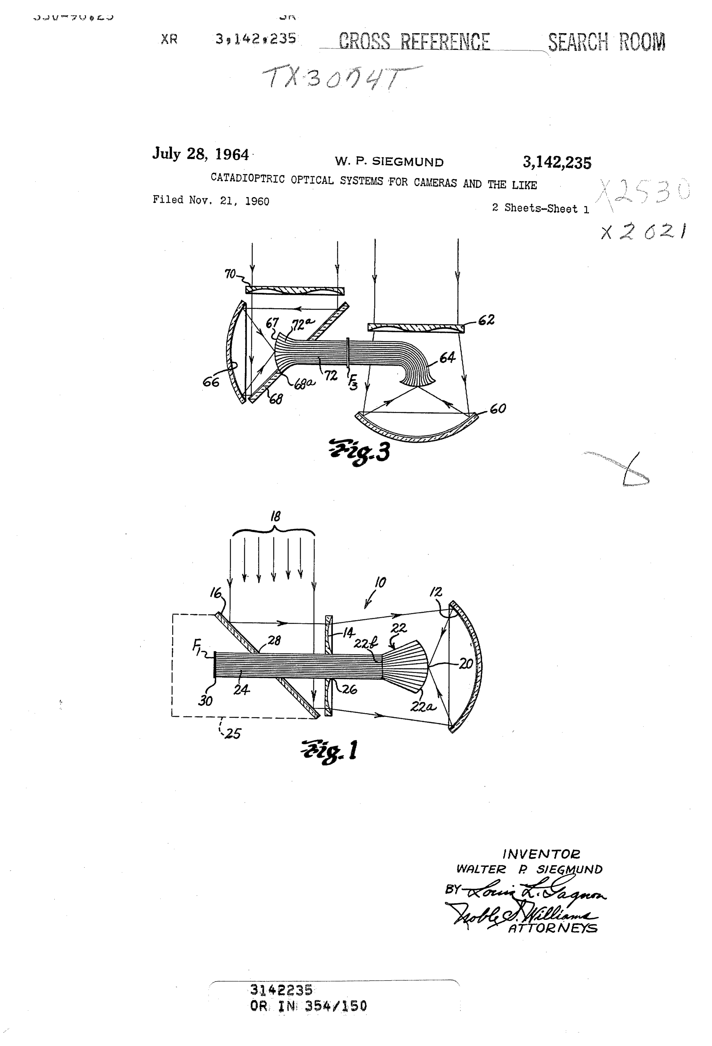
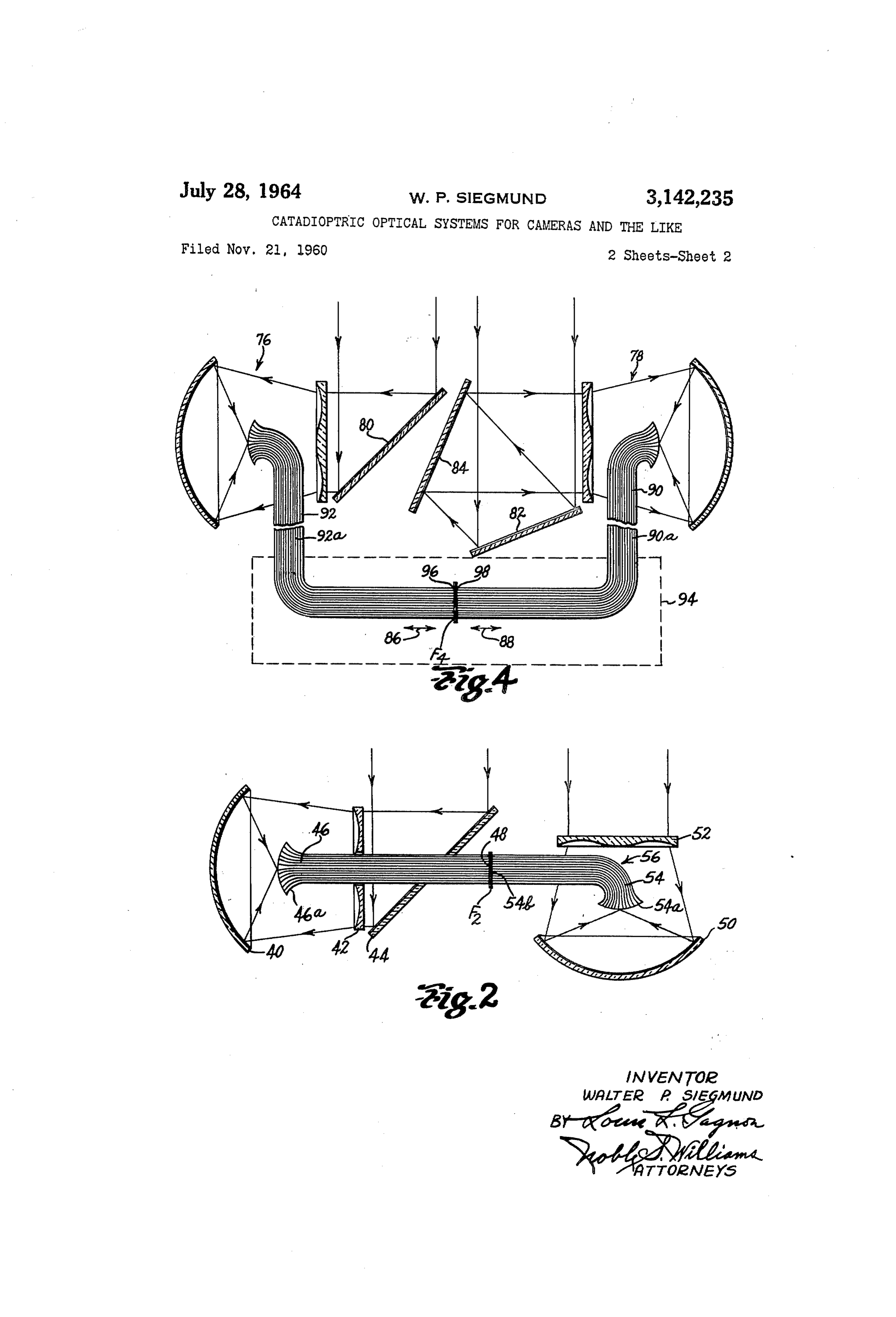
tems of the catadioptric type, and more particularly re FIG. 1 is a longitudinal sectional view showing a re lates to catadioptric systems for use with cameras or flecting type image-forming optical system and fiber op the like and provided with fiber optical means for en tical image relay means associated therewith. abling such optical systems to be operated at higher nu FIG. 2 is a longitudinal sectional view showing two as merical apertures, or at wider angular object fields, or sociated reflecting image-forming optical systems, fiber both, than heretofore. optical relay means and reflecting optical components for While a reflecting type image-forming optical system effecting a combined photographic system; for use with a camera or the like and employing a spheri FIG. 3 is a longitudinal sectional view somewhat simi cal mirror and an aspherically curved Schmidt-type cor lar to FIG. 2 but showing a modified form of combined rector plate for compensating for the inherent spherical 20 photographic system; and aberrations of the mirror is well known, nevertheless, the FIG. 4 is a view somewhat similar to FIG. 3 but show use of such a reflecting optical system has been consider ing a modified form of combined image-forming optical ably restricted in the past because of the limitations im systems for photographic purposes, or the like. posed thereon by having its primary image formed with Referring to the drawing in detail and in particular to in the boundaries of the system. Furthermore, even FIG. 1, it will be seen that a catadioptric optical system though it has been possible to use, for example, an angul is indicated generally by the numeral 10 and comprises a larly disposed plane mirror centrally within such a re concave spherically curved front surface mirror 12 ar flecting system to relay the image-forming light rays ranged in optical alignment with a Schmidt-type aspheri thereof laterally to a focal plane outside the system, such cally curved corrector plate or element 14. As is well an additional mirror has not been satisfactory since it can 30 known, such a corrector plate is for providing negative only be used in a system of relatively low numerical aper spherical aberration of such a value as to compensate to a ture or of very limited angular object field. high degree for the inherent spherical abberation of the It has now been found, however, that such a catadiop spherical mirror 12. Positioned forwardly of the correc tric type image-forming optical system having the desir tor plate 14 is an angularly disposed plane mirror 16 and able qualities of high light-gathering ability with good this mirror, it will be appreciated, is arranged to receive imagery, good field coverage, and freedom from chro light rays such as rays 18 coming from a distant axial matic aberrations, astigmatism, distortion and coma, can object field, and to reflect same in a direction at 90 there be employed in a camera or the like and combined with to so as to pass through corrector plate 14. a fiber optical bundle of proper design and suitable loca The result of such an arrangement is that light rays tion within the system in such a manner as to act as an 40 from a distant object field, such as that of an aerial or image relay device capable of receiving the appreciably astronomical camera, will be brought to a real image by curved primary image being formed within the system the corrector plate and the mirror at an image surface 20 and conducting same at increased optical speed to a flat internally of the optical system and that this real image image plane located outwardly thereof. will have appreciable curvature of field. Even though Additionally, the invention includes optical components 45 heretofore a plane mirror has been located within such a and means in combination with a pair of improved com catadioptric system for reflecting image-forming rays to bined systems in such a manner as to direct separate sets a location outwardly of the system, such an arrangement of image-forming light rays from the same object field on cannot be used by the system of FIG. 1 without necessi to opposite sides of a single sensitized film and at such tating a material reduction in the numerical aperture or size and in such registry with each other that substantially the degree of angular field being accommodated by the double light intensity will be supplied the film during a system. Thus, it will be readily apparent that reflecting single exposure thereof, whereby shorter exposures and optical systems of this type heretofore have been material thus pictures at higher rates of speed may be obtained. ly restricted.
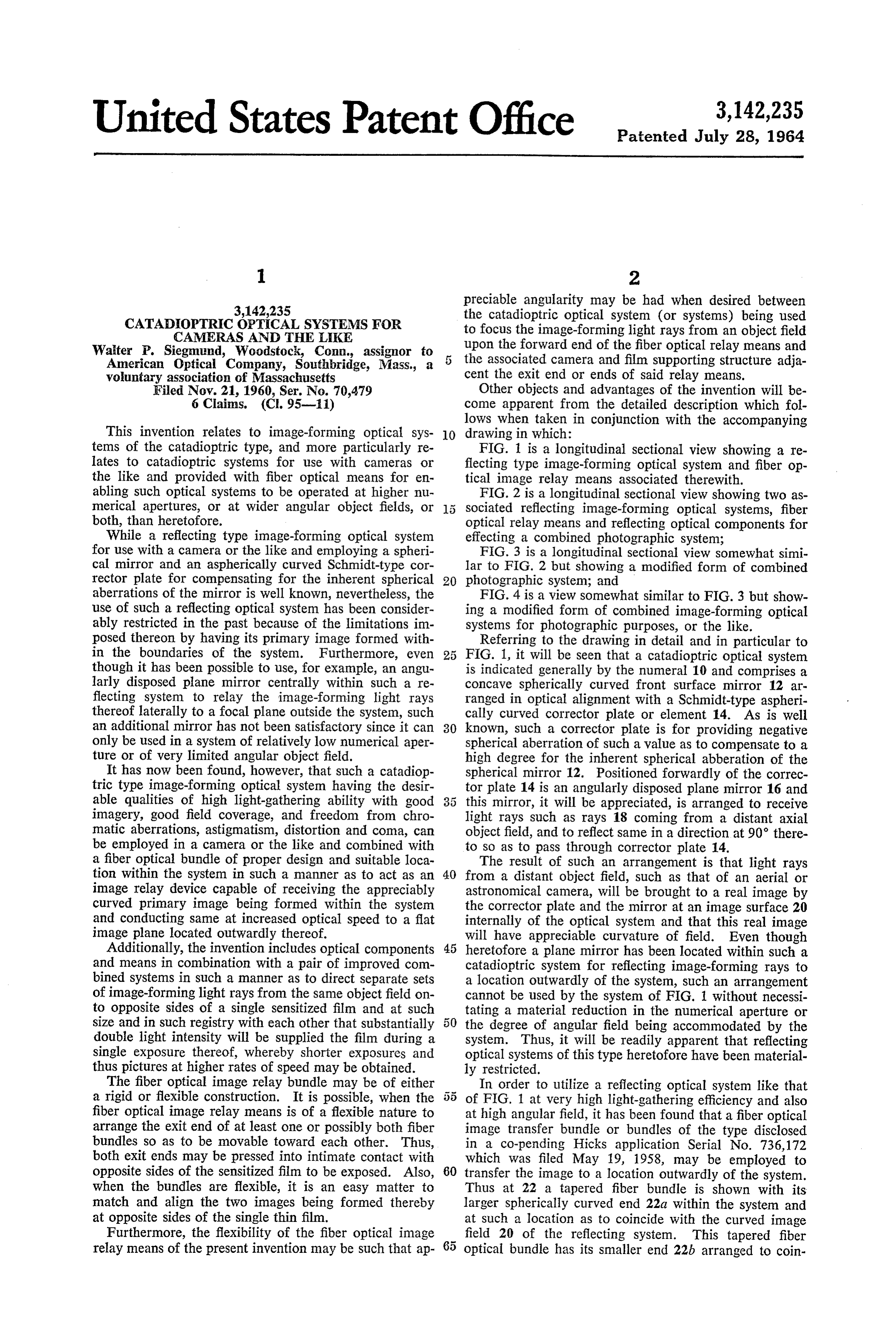
The fiber optical image relay bundle may be of either In order to utilize a reflecting optical system like that a rigid or flexible construction. It is possible, when the s5 of FIG. 1 at very high light-gathering efficiency and also fiber optical image relay means is of a flexible nature to at high angular field, it has been found that a fiber optical arrange the exit end of at least one or possibly both fiber image transfer bundle or bundles of the type disclosed bundles so as to be movable toward each other. Thus, in a co-pending Hicks application Serial No. 736,172 both exit ends may be pressed into intimate contact with which was filed May 19, 1958, may be employed to opposite sides of the sensitized film to be exposed. Also, 60 transfer the image to a location outwardly of the system. when the bundles are flexible, it is an easy matter to Thus at 22 a tapered fiber bundle is shown with its match and align the two images being formed thereby larger spherically curved end 22a within the system and at opposite sides of the single thin film. at such a location as to coincide with the curved image Furthermore, the flexibility of the fiber optical image field 20 of the reflecting system. This tapered fiber relay means of the present invention may be such that ap optical bundle has its smaller end 22b arranged to coin
Page 4
cide with one end of an elongated straight-sided fiber In FIG. 3, a somewhat different combined optical optical bundle 24 which extends centrally within the system is disclosed but same will accomplish substantially system and passes outwardly through a central aperture the same end result as that produced by the combined 26 provided therefor in the aspheric corrector plate 14. optical system of FIG. 2. While a concave spherical An aperture 28 is also provided in the plane angularly mirror 60, an aspheric corrector plate 62 and a fiber arranged reflector 6 and thus the exit end of the bundle optical bundle 64, in FIG. 3, are like those shown at 24 may extend to a terminal location 30 outwardly of the right side of FIG. 2, the construction and arrange the system per se but, nevertheless, still within the con ment of components for the system at the left side of fines of a camera housing indicated by dotted line 25. FIG. 3 are different. A concave spherical mirror 66 Accordingly, it is an easy matter to arrange photo O which forms a real image at the curved focal plane 67 graphic film, as diagrammatically indicated at F1, with within the optical system receives its light rays from an its emulsion side in contact with this outer fiber bundle angularly disposed plane mirror 68 which is aligned with end for photographic purposes, or the like. Even though an aspheric corrector element 70. Thus, light rays from some of the light rays 18 travelling toward the mirror a distant object field which pass through plate 70 and 16 will be blocked out by the fiber bundle, nevertheless, 5 are laterally reflected by the mirror 68 before impinging an image at high optical speed and appreciable angular upon the spherical mirror 66 are imaged thereby at focal field will be formed at the curved image plane 20. Also, plane 67. The plane mirror 68, however, is centrally it should be clear that since the larger end 22a of the apertured, as indicated at 68a, and disposed within this fiber optical bundle 22 may be finished so as to have a aperture is a fiber optical bundle 72 which has its ta curvature corresponding closely to the curvature of field 20 pered forward end 72a convexly spherically curved so of the real image formed by the catadioptric system and as to fit closely the curvature of field of the real image since a taper of suitable value may be provided the bun being formed by the optical system. By this arrangement, dle 22, it is possible to arrange these parts so as to accept a somewhat more compact combined optical system may and utilize the high light-gathering ability and the rela be effected than in FIG. 2 but the results obtained by this tively large angular object field afforded by the system. 25 modified form of the invention in supplying matching Also, since each fiber of the bundle 22 is tapered, the images to the opposite sides of the film F are substantial light entering each fiber will be concentrated as it passes ly the same as those obtained in FIG. 2. through the fiber to the opposite end thereof. This, of In FIG. 4, a further modified construction of combined course, will effect an increase in intensity of illumination catadioptric optical system for providing double light at the smaller exit end of bundle 22 and thereafter for 30 intensity upon a photographic film F is shown. In this the light rays travelling through the elongated bundle 24 arrangement, however, even though the reflecting type and to the film in contact with the exit end thereof. image-forming systems 76 and 78 thereof are each quite In FIG. 2, a spherical mirror 40, a corrector plate 42, similar to that disclosed at the right side of FIG. 2, a plane mirror 44 and a fiber optical bundle 46 are shown nevertheless, in order to have the two images being and it will be appreciated that these parts are much like 35 formed thereby rightly oriented and in proper matching those already discussed in FIG. 1 for conducting the relation with each other but at opposite sides of the film optical image to the emulsion on the film F. One differ FA, there is provided, for the left side, an angularly dis ence does exist, however, in that the fiber optical bundle posed plane mirror 80 and at the right side a first an 46 is formed as a single unit instead of two separate fiber gularly disposed plane mirror 82 and a second angularly optical units. This bundle 46, instead, has an enlarged 40 disposed plane mirror 84 in properly oriented relation forward end formed by fibers which are tapered at their thereto. Thus, by the use of one more mirror in the forward end 46a, as shown, and are integral with the right side of the combined system than in the left side, elongated straight-sided portions extending outwardly of it is possible to so oppositely rotate or orient the two the system so as to terminate in a flat surface 48 adjacent real images being supplied to opposite sides of the emul the photographic film F associated therewith. How sion surface of the film F that a proper matching of ever, in FIG. 2, a second reflecting optical system has been 45 images with double light intensity will be provided there shown and comprises a concave spherical mirror 50, an for.
aspheric corrector plate 52, and a fiber optical bundle Additionally, in FIG. 4, there is indicated by the double 54. This system, however, is of somewhat different con arrows 86 and 88 that movement of the exit ends of struction in that not only do the individual fibers at either or both fiber bundles 90 and 92 toward or away their forward end 54a taper so as concentrate light being 50 from the film F4 can be had and this would be without transmitted thereby but also these fibers are curved, as requiring any movement of either reflective optical sys indicated at 56, in such a manner as to transport the tem 76 or 78 relative to the other. This would be pos image-forming light rays laterally and outwardly of the sible optical System without passing through the corrector plate bundlewhen 90 or the intermediate portion 90a of the fiber the intermediate portion 92a of the bundle 52. The result is that approximately the same amount 55 92 is made flexible and arranged to accommodate such of light will be blocked out as was the case in the arrange movement. Also, the box-like dotted lines 94 are in ment of FIG. 1. tended to indicate the confines of a camera structure, or The outer flat end 54b of the bundle 54, however, is the like which, it should be appreciated, may be suffi arranged in contacting engagement with the opposite ciently removed from the reflecting image-forming opti side of the film F2 in such a manner as to be in matching 60 cal systems 76 and 78 of the combined system so that relation, so to speak, with corresponding fibers of the angular movement of the combined image-forming sys fiber optical bundle 46. In this instance, the film F, tem may be had without necessitating movement of any should be relatively thin in order to avoid spreading of structure within the box-like camera portions of the de the light passing through the film to the emulsion. Since the plane mirror 44 reflects the light rays which it receives 65 vice. Also, within this box-like portion, means (not toward the left and effects a quarter turn thereof before shown) may be provided whereby a suitable liquid or reaching the corrector plate 42 and the curved fiber Semi-liquid may be applied to opposite sides of the film bundle 54 for transferring the image formed by the mir at exit areas 96 and 98 of the fiber bundles. This liquid ror 50 is bent to the left, the end result will be that each or Semi-liquid would be to insure complete optical con unit area of the film emulsion will be simultaneously O tact between the film and the ends of the fibers of both exposed to corresponding areas of the two images being bundles 90 and 92, with the result that a much higher formed by the left and right-hand parts of the combined acceptance angle for the light rays leaving the ends of optical System. Thus, the amount of light being provided the fiber and impinging upon the emulsion of the film for forming the image on the film will be substantially may be had than would be possible if no such optical twice that obtainable for the film in FIG. 1. 75 contact Were provided.
Page 5
Of course, when considering the angular field to be predetermined film exposure position in said camera, and covered by the high-speed optical systems of the present plane mirror means disposed in the path of the light rays invention, care must be exercised in the relative position of each of said systems so as to intercept the light rays ing and arrangement of the mirrors and other com thereof and direct same toward the concave mirrors as ponents of the system so that no material vignetting of 5 sociated therewith, whereby a mirror image reversal of the more oblique light rays from the object field of the said light rays of one of said systems will be effected and system will occur; and, of course, this is a distinct and the light rays of both systems will form a pair of real separate problem from that of keeping the obscuration images in matching relation upon opposite sides of the ratio of the system as low as conveniently possible, the photographic film at said exposure position. ratio, of course, being controlled by the size of fiber 10 4. A camera or the like having relatively high-speed bundle and image surface being used within the system. optical means for forming an image of an object field Having described my invention, I claim: upon photographic film within said camera, said optical 1. A camera or the like having relatively high-speed means comprising a pair of catadioptric optical systems optical means for forming an image of an object field each having a concavely curved spherical mirror and an upon photographic film within said camera, said optical aspheric corrector plate in optical alignment and pre means comprising a pair of catadioptric optical systems determined spaced relation to each other, the corrector each having a concavely curved spherical mirror and an plate and spherical mirror of each of said optical systems aspheric corrector plate in optical alignment and pre being arranged to receive light rays from a single object determined spaced relation relative to each other, the field spaced therefrom and to focus said light rays as a corrector plate and spherical mirror of each of said opti 20 pair of real images having appreciable curvature of field cal systems being arranged to receive light rays from a at a pair of curved image planes within said system, re single object field spaced therefrom and to focus said light spectively, and optically disposed between the mirrors rays as a pair of real images having appreciable curvature and the corrector plates thereof, a pair of elongated fiber of field at a pair of curved image planes within said sys optical image-transfer bundles having their inner ends of fems, respectively, and optically disposed between the predetermined size and of predetermined convexly curved Inirrors and the corrector plates thereof, a pair of elon shape and so disposed with said systems, respectively, as gated fiber optical image-transfer bundles having their to be in substantial coincidence with said curved image inner ends of predetermined size and of predetermined planes of said systems, said elongated fiber optical convexly curved shape and so disposed within said sys bundles extending outwardly of said systems and having tems, respectively, as to be in substantial coincidence 30 their outer end surfaces substantially flat, and at least one With Said curved image planes of said systems, said elon of said flat end surfaces being movable relative to the gated fiber optical bundles extending outwardly of said other so as to be brought into contacting relation with Systems and having their outer end surfaces substantially said film at a predetermined film exposure position in said flat and so disposed as to contact opposite sides of camera, and plane mirror means disposed in the path of a photographic film at a predetermined film exposure the light rays of one of said systems so as to intercept said position in said camera, and plane mirror means disposed last in the path of the light rays of one of said systems so as mirrormentioned light rays before reaching the concave associated therewith, whereby, a mirror image re to intercept said last mentioned light rays and cause a mirror image reversal thereof before reaching the con 40 versal of said last mentioned light rays will be effected and the light rays of both systems will form a pair of real cave mirror associated therewith, whereby the light rays images in matching relation upon opposite sides of the of both Systems will form a pair of real images in match photographic film at said exposure position. ing relation upon opposite sides of the photographic film 5. A camera or the like having relatively high-speed at said exposure position. optical means for forming an image of an object field 2. The combination defined in claim 1 in which at upon photographic film within said camera, said optical least one of said elongated fiber optical bundles is of such means comprising a pair of catadioptric optical systems flexibility intermediate its opposite ends as to allow move each having a concavely curved spherical mirror and an ment of its flat outer end surface between its film contact aspheric corrector plate in optical alignment and prede ing position and an out-of-the-way position to thereby termined spaced relation relative to each other, the cor allow ready insursion of photographic film between the rector plate and spherical mirror of each of said systems adjacent flat end surfaces of said bundles at said exposure being arranged to receive light rays from a single object position. field spaced therefrom and to focus said light rays as a 3. A camera or the like having high-speed optical pair of real images having appreciable curvature of field means for forming an image of an object field upon at a pair of curved image planes within said systems, re photographic film within said camera, said optical means spectively, and optically disposed between the mirrors and comprising a pair of catadioptric optical systems each the corrector plates thereof, and fiber optical means for having a concavely curved spherical mirror and an transferring said real images from said curved image aspheric corrector plate in optical alignment and pre planes within said systems to a pair of flat exit surfaces determined spaced relation relative to each other, the cor 60 thereon outwardly of said systems, respectively, the fiber rector plate and spherical mirror of each of said optical optical means for each system comprising a tapered fiber systems being arranged to receive light rays from a single optical portion for concentrating the light rays being re object field spaced therefrom and to focus said light rays ceived at its larger end, and an elongated substantially as a pair of real images having appreciable curvature of parallel-sided fiber optical portion aligned therewith and field at a pair of curved image planes within said systems, extending outwardly of said system, each tapered portion respectively, and optically disposed between the mirrors having its larger end of such a predetermined size and and the corrector plates thereof, a pair of elongated fiber predetermined convexly curved shape and so located with optical image-transfer bundles having their ends of pre in its respective system as to be in substantial coincidence determined size and of predetermined convexly curved with the curved image plane associated therewith, the shape and so disposed within said systems, respectively, flat exit surfaces of said parallel-sided portions being so as to be in substantial coincidence with said curved image disposed relative to each other as to be closely adjacent planes of said systems, said elongated fiber optical opposite sides of photographic film at a predetermined bundles extending outwardly of said systems and having film exposure position in said camera, and mirror means their outer end surfaces substantially flat and so disposed disposed in the path of the light rays of one of said sys as to contact opposite sides of a photographic film at a 5 tems So as to reflect said light rays and cause a mirror
Page 6
image reversal thereof before reaching the concave mir References Cited in the file of this patent ror of said one system, whereby said light rays will form UNITED STATES PATENTS a pair of real images in matching relation upon opposite 1,173,083 Banks ----------------- Feb. 22, 1916 sides of the photographic film at said exposure position.
6. The combination defined in claim 5 in which at 2,354,591 Goldsmith -------------- July 25, 1944 least one of said elongated parallel-sided portions is of 2,697, 182 Sheldon --------------- Dec. 14, 1954 such flexibility intermediate its opposite ends as to allow 2,794,380 Rehorn ----------------- June 4, 1957 movement of its flat exit surface between its film contact 2,825,260 O'Brien ---------------- Mar. 4, 1958 ing position and an out-of-the-way position to thereby OTHER REFERENCES allow ready insursion of photographic film between the Article: “Fiber Optics. Part III, Field Flatteners,' adjacent flat end Surfaces of said bundles at said exposure Journal of the Optical Society of America, vol. 47, No. position. 7, July 1957, pages 594-598.

Provenance
- Collection
- Cited prior art
- Original PDF
- patentimages.storage.googleapis.com →
- Filed
- 1960-11-21
- Pages
- 6
- Method
- pdftotext (the PDF's own text layer) + pdftoppm 300dpi page scans
- Source
- Google Patents bibliographic record
- Granted
- 1964-07-28
- Inventors
- Walter P Siegmund; American Optical Corp
- Transcribed from
- patentimages.storage.googleapis.com →