patent · US4459177
Ground moisture transfer system
10 July 1984
Page 1 — bibliographic record
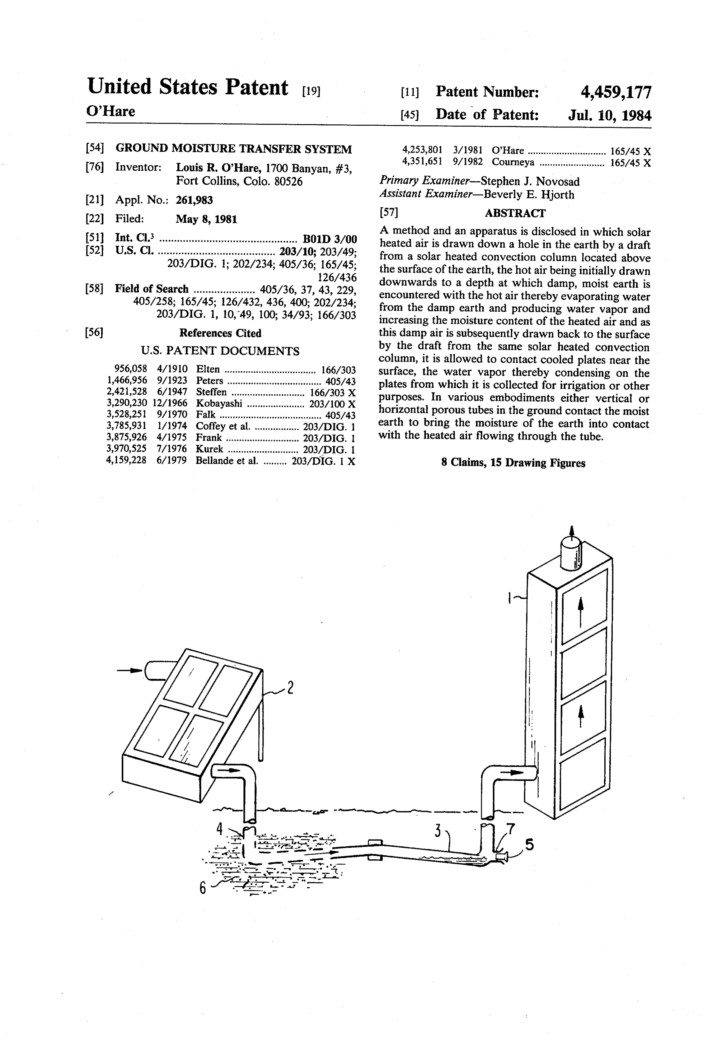
United States Patent (19) 11) Patent Number: 4,459,177 O'Hare (45) Date of Patent: Jul. 10, 1984 54 GROUND MOISTURE TRANSFER SYSTEM 4,253,801 3/1981 O'Hare .............................. 165/45 X
76 Inventor: Louis R. O'Hare, 1700 Banyan, #3,
Fort Collins, Colo. 80526 Primary Examiner-Stephen J. Novosad 21 Appl. No.: 261,983 Assistant Examiner-Beverly E. Hjorth 22 Filed: May 8, 1981 57) ABSTRACT 51 Int. Cl. ............................................... B01D 3/00 A method and an apparatus is disclosed in which solar 52 U.S. Cl. ........................................ 203/10; 203/49; heated air is drawn down a hole in the earth by a draft from a solar heated convection column located above 203/DIG. 1; 202/234; 405/36; 165/45; the surface of the earth, the hot air being initially drawn 126/436 downwards to a depth at which damp, moist earth is 58 Field of Search ..................... 405/36, 37, 43, 229, encountered with the hot air thereby evaporating water 405/258; 165/45; 126/432, 436, 400; 202/234; from the damp earth and producing water vapor and 203/DIG. 1, 10,49, 100; 34/93; 166/303 increasing the moisture content of the heated air and as 56) References Cited this damp air is subsequently drawn back to the surface
column, it is allowed to contact cooled plates near the 956,058 4/1910 Elten ..... ... 166/303 surface, the water vapor thereby condensing on the 1,466,956 9/1923 Peters .................................... 405/43 plates from which it is collected for irrigation or other 2,421,528 6/1947 Steffen ...... ... 166/303 X purposes. In various embodiments either vertical or
3,528,251 9/1970 Falk ....................................... 405/43 horizontal porous tubes in the ground contact the moist 3,785,931 1/1974 Coffey et al. . ... 203/DIG. 1 earth to bring the moisture of the earth into contact 3,875,926 4/1975 Frank ............ ... 203/DIG. with the heated air flowing through the tube. 3,970,525 7/1976 Kurek ........................... 203/DIG. 1 4,159,228 6/1979 Bellande et al. ......... 203/DIG. 1 X 8 Claims, 15 Drawing Figures
Page 2
Drawing sheet — no readable text.
Page 3
Drawing sheet — no readable text.
Page 4
Drawing sheet — no readable text.
Page 5
Drawing sheet — no readable text.
Page 6
Drawing sheet — no readable text.
Page 7
ture, that is found only at a considerable depth, closer to
GROUND MOSTURE TRANSFER SYSTEM the surface area and in this way to provide a solar pow ered watering system for trees and other vegetation as
This invention is a type of solar still in that it removes well as potable water.
water from damp earth by using heat to evaporate the In previous applications a solar powered draft from water from the earth and then by condensing the water an open ended convection column has been used to vapor on a cool surface. In this way it resembles the transport heat energy to various objects and for various survival still that is used in the desert under extreme other purposes, Forinstance in my copending applica conditions to obtain drinking water from damp subsur tion called, "Convection Powered Solar Engine' Ser. face earth. In the case of the classic survival solar still, 10 No. 184,205 solar heated air is drawn into a chamber to a hole is dug in the desert earth and a piece of transpar expand a bellows. Again in my copending application ent material such as plastic flexible sheet is stretched called, “Convection Powered Solar Food Dryer' of over the hole. A depression is then made in the center of Ser. No. 234,970 hot air from a solar collector is drawn this flexible plastic cover and a receptacle is placed across drying food by a draft from an open ended, solar under the point of the depression with the effect that 15 heated convection column. Another example is the use when solar radiation evaporates water from the damp of a draft from a convection column to draw solar earth into the air intervening between the plastic and heated air through a water tank to heat the water in the the earth, then the water vapor in the air condenses tank even though the water tank may be at a lower onto the underside of the plastic and courses down the elevation than either the column or the collector. This plastic toward the center of the depression and drips 20 copending application is called, "Convection Powered into the receptacle. Like this traditional system which Solar Heater for Water Tanks'. This system of heat has saved many lives in desert regions by providing transport is also used in my copending application water from damp earth, this present invention also uti called, “Thermal Dielectric Power Generator' of Ser. lizes solar energy to remove moisture from damp earth No. 198,359 in which hot air is intermittantly drawn by heating the earth and evaporating its water and then 25 across temperature-variable capacitors. However, in subsequently condensing the water vapor. However, in this present application a solar heated convection col this present invention additional means are provided umn powers a draft that is used not only to transport which greatly extend the usefulness of the concept. In heat energy but also to evaporate water and then to this present invention means are provided for heating transport water vapor and finally to bring the vapor to damp earth at a remote distance from the area of solar 30 a cool area for condensation in order to provide water radiation impingement in order to bring water from in a different area.
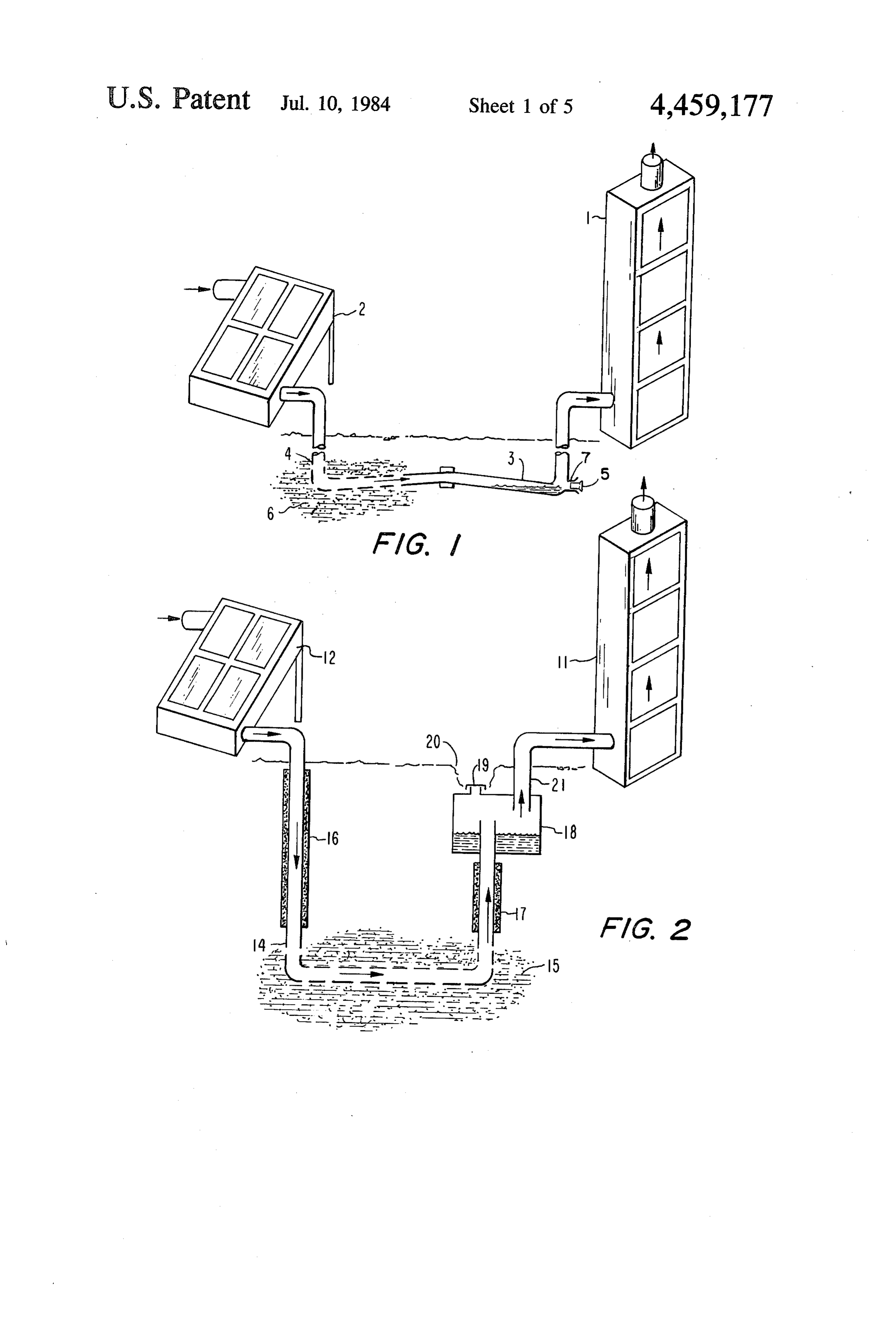
damp ground deep in the earth. This invention makes Clarification of the basic method of this invention available water from a source from which it would not along with the structures which make the method oper ordinarily be available. It makes water available from able can be seen in the following drawings. damp earth deep in the ground. But not only does this 35 FIG. 1 of the drawings illustrates a simple horizontal invention make water available from such a source but moisture transfer system with a solar collector and con it transports it to the surface or to an area near the vection tower and a duct leading from a damp area to a surface. In this invention the method of transporting the dry area to be wetted.
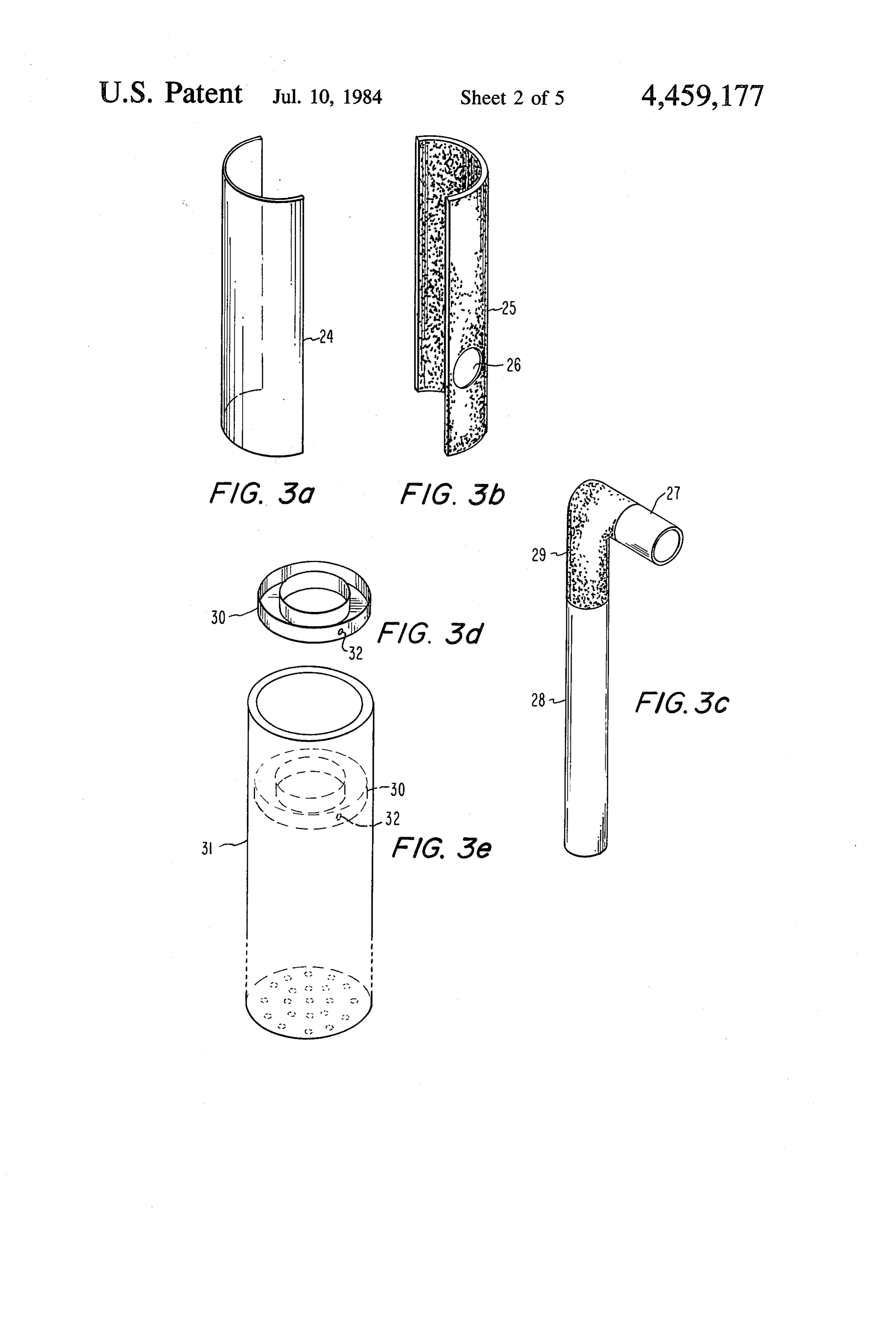
heat downwards for the purpose of evaporating water FIG. 2 shows a collector and a column transporting from the earth or even from a pool is novel in that a 40 moisture from a damp area below to a condensing water draft from a solar heated convection column draws air trap at a higher elevation. from a solar heater downwards to the subterranean FIG. 3a–FIG. 3e of the drawings show some compo water and then draws the moisture laden air to the nent parts of a simple cylindrical transport system to be surface. This invention also provides an advantage in used for vertical transport of moisture. The components condensation cooling to more effectively remove the 45 include the transparent glaze of a cylindrical collector water from the moist air. In the case of this present with the black body absorber.
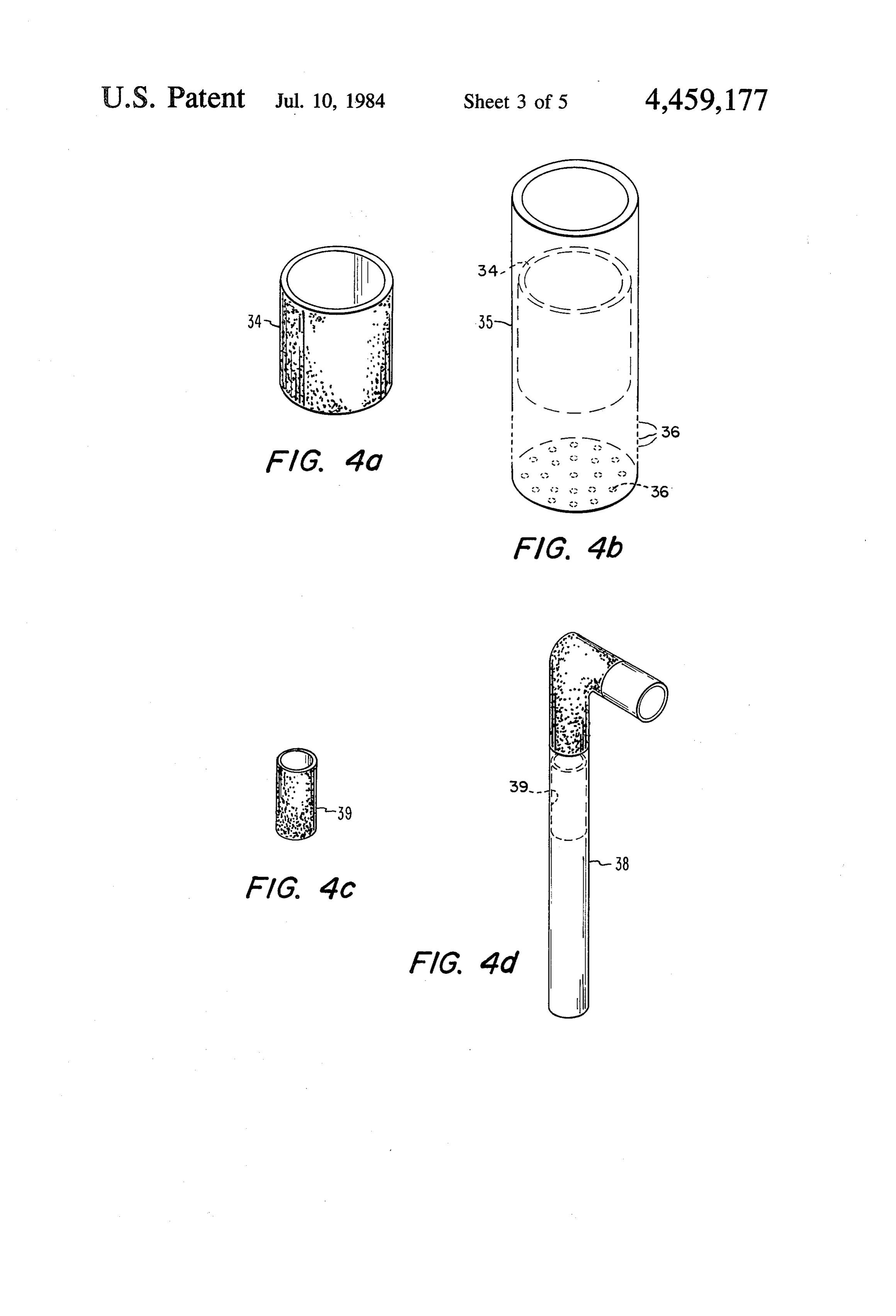
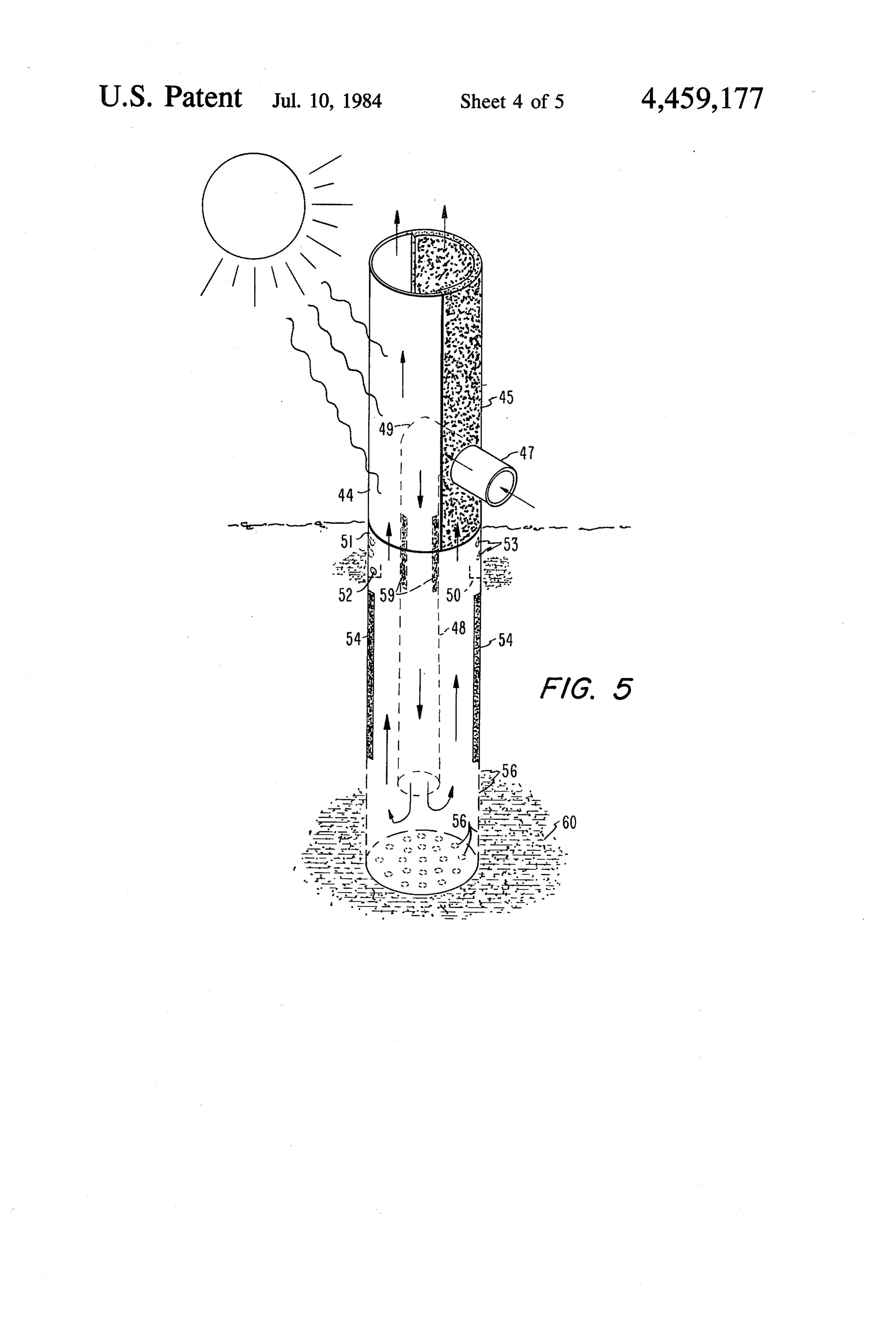
invention the condensing surface is made cool not by FIG. 4a-FIG. 4d of the drawings show other compo ambient air as in the case of the plastic cover used in the nents of the cylindrical, vertical transport system de survival art but rather the cooler subsurface earth re picting insulation collars and their positions. moves the heat of condensation from the condensing 50 FIG. 5 of the drawings shows the assembled compo plates. The principal object of this invention then is to nents in their relative positions on the vertical moisture provide water for irrigation and other purposes from transport column.
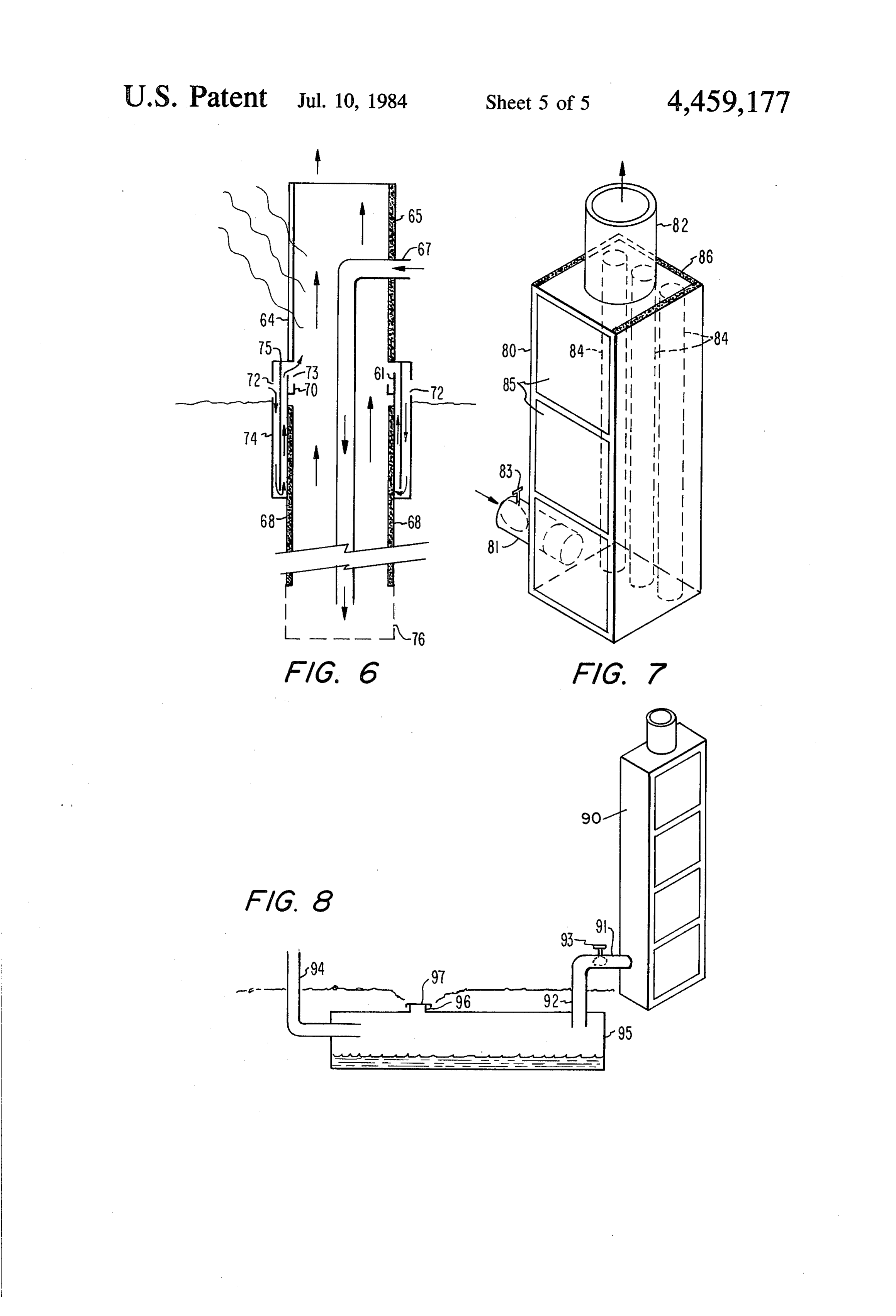
damp earth located at a significant depth below the FIG. 6 shows a cross sectional diagram of a cylinder surface. Another object of the invention is to concen with concentric chambers used to cool air beneith the trate moisture diffusely distributed over a wide area of 55 surface and to use the cooled air to provide condensa subsurface soil into smaller areas in order to provide in tion above the earth's surface.
those smaller areas sufficient densities of moisture to FIG. 7 shows a solar heated convection column with enable the growth of plants and trees etc. Again another heat storage.
way of stating the objective of this invention is from the FIG. 8 shows a ground moisture transfer in which air perspective of the energy to be used and in this sense the 60 moisture at night is transferred to the ground. object is to use solar energy to transfer moisture from In FIG. 1, solar heated convection column 1 is an either deep in the earth or from an area in which it is air-heating solar black box collector that is positioned widely diffused to a smaller area near the surface where with its length dimension in a vertical plane. Internally it is thereby made readily available in sufficient concen heated air rises from an inlet at the base to an exit at the tration for plant growth or drinking purposes etc. An 65 top causing a draft at the base. This draft draws hot air other object of the invention is to provide a single unit from collector 2 through evaporation duct 4 into con moisture transfer structure which can simply be low densing duct3. The duct 4 has small holes in the form of ered into a hole in the ground in order to bring mois perforations or pores through which moisture from wet
Page 8
earth enters 4 by capillary action and soaking. The formed by 24 and 25. The FIG. 3d shows a circular moisture is evaporated into the hot air stream in 4 and trough formed to receive condensing moisture. This carried to duct 3 which is cooled by the surrounding trough 30 is placed inside of cylinder 31 of FIG. 3e in earth, and the moisture of the airstream condenses in 3. such a way that the outside surface of its outside cylin The water formed by condensation in 3 may be re drical wall contacts the inside surface of the cylindrical moved from the bottom of 3 by a ladel or a pump or a wall of 31 so that any moisture condensing on the wall siphon etc. These are not shown but are understood in of 31 above 30 will drain into 30. An optional hole 32 in the art. The water may also be removed by removing the outer wall of 30 aligns with a hole (also optional) in stopper 5 from exit duct 7. Any type of valve or porous the wall of 31. In the FIG. 3e the cylinder 31 with its material may be used in the place of this exit duct and 10 trough 30 in place is positioned into a deep hole in the the water may be drained into the earth. In this way earth which has wet earth or water at the bottom of the water is transported from damp earth 6 horizontally to hole. The bottom surface of 31 is of porous or perfo a position under duct 3. rated material and it is made to contact the damp earth Referring then to FIG. 2 of the drawings, the solar thereby moistening the inside of 31 at the bottom. Air, heated convection column 11 is the same as the column 15 heated in the cylinder formed by 24 and 25 of FIGS. 3a 1 of FIG. 1. The draft produced at the base of 11 in this and 3b when sunlight enters through 24 and warms 25, FIG. 2 draws hot air from solar collector 12 down to rises and draws air upwards through connected cylin the damp earth deep in the ground through evaporation der 3. The draft formed by the rising air draws heated duct 4 which is made of porous material in its low area air down cylinder 28. The warm air moving down 28 is in which it traverses wet earth or pools of water shown 20 heated at the top of 28 and in 27 and in elbow 29 as these by darkened area 15. The insulation 16 and 17 on the elements are exposed to solar radiation and the heat upper sections of duct 14 retain heat in the heated draft formed within the solar collector area. However, the of air so that it will respectively have sufficient heat for length of the convection column due to the height of 24 evaporation purposes and not lose its water vapor prior and 25 is significantly greater than the length of cylin to arriving at the condensing water trap 18. When mois 25 der 28. The stronger upward convecting tendency of ture laden air is drawn through 18 it gives up its heat of the cylinder composed of 24 and 25 draws heated air condensation to the walls of 18 and the water vapor down 28 and up through 31. As the air moves it evapo condenses filling 18. The water may be removed from rates moisture at the base of 31 and receives water 18 by opening pressure sealing cap 19 which is reached vapor into its air stream. This water vapor is maintained through a hole in the ground 20. When water is not 30 in the air atream by conserving the heat of the air in the being removed the cap must be replaced to asure that stream until the air reaches an area close to the earth's the draft is transmitted to the solar air heater. Other surface. In that area the air is allowed to contact the obvious means of water removal are not shown because cooled walls of cylinder 31 and the moisture condensing they are well known in the are of water transport. These on the walls is collected by trough 30. Insulating collars include draining the water into the soil through a faucet, 35 shown in the following FIG. 4 are the means by which or the use of a small hand pump or a siphon etc. The the heat is conserved in the air stream. Water may be essential element of this FIG. 2 is the elevated position removed from the trough 30 through optional holes of the water chamber 18 whereby the energy of the such as the optional hole 32 which is drilled through 31 convection column and the energy of the heat from the and the outer ridge of trough 30. Water leaving the solar collector have operated to remove the water from transfer system at this point may be used to water the the wet earth below and transport it to a level at which roots of trees and other vegetation by moistening the it is accessible. The duct 21 communicates the draft ground around them. In another embodiment instead of from convection column 11 to condensing chamber 18. the optional holes water may be siphoned from trough Referring then to FIG.3 of the drawings, in the FIG. 30 or pumped from it for other uses. Referring then to 3a the transparent glaze, which admits solar radiation 45 FIG. 4 of the drawings, the insulation collar 34 of FIG. both to produce heat within a cylinder-shaped collector 4a is placed in cylinder 35 of FIG. 4b. The cylinder 35 and convection column, has a shape which forms ap of FIG. 4b is the same as 31 of FIG. 3e but for clarity it proximately half of the wall of a cylinder that is divided is shown here without the trough. This collar 34 is along its length. This glaze 24 is shown opposite to the placed in a position in the cylinder immediately below insulated black body collecting surface 25 of FIG. 3b. 50 the trough shown in FIG. 3e and the insulation collar The glaze 24 and the insulated black surface 25, which extends downwards along the inner wall of the cylinder has insulation over the outer part of its entire area, is to a position immediately above the perforated area at also in the form of one half of a cylinder that has been the bottom of 35. Pore holes 36 indicate the area at divided along its length and it is able to form a complete which moisture is admitted through porous surface or cylindrical shape when joined along its length with the 55 perforations.
opposite half cylinder of glaze 24 in such a way that the In the FIG. 4c the small collar of insulating material concave sides of both 24 and 25 are facing eachother. is placed inside the interior cylinder 38 or it may be Hole 26, projecting through the wall of 25, is for the placed around the outside of 38 at a position on 38 that purpose of receiving a small cylinder. FIG. 3c shows is opposite the cool area near the top of 35. Since 28 of the small cylinder 27 which fits into hole 26 in such a 60 FIG. 3c is the same as 38 of this FIG. 4d, it is advanta way that when 27 is in place the long cylinder 28 ex geous to to keep the heated air in 38 as warm as possible tending downward from elbow 29 will be inside of and for evaporation purposes at the bottom of 35. But the air coaxial to the cylinder formed by the joining of 24 and moving down 38 also warms some air rising in 35 25. This inner cylinder 28 will extend downward and through the heat transfered through the walls of 38. It is far below the lower limit of the cylinder formed by 24 65 not necessary to transfer heat through the walls of 38 in and 25. The inner cylinder 28 will further extend for a the area in which cooling is taking place on the walls of great length into the cylinder 31 of FIG. 3e when the 35, hence insulating collar 39 is useful in that position cylinder 31 is placed end to end with the cylinder but it is not essential and it is optional.
Page 9
Referring then to FIG, 5 which shows the final com and then drawn up to cool an area of 61 above ground posite relationship of the component parts shown in the level, the trough 70 receiving the condensed water is previous two figures, the glaze 44 is the same as the also located above ground level in the embodiment of glaze 24 of FIG, 3a and it is shown here in this FIG. 5 this drawing. The water may be drained through an in its position immediately above the surface of the 5 optional hole in the trough like the optional hole 52 earth. The collecting surface for converting sunlight to shown in FIG. 5. The draft that draws in the cooling air heat together with its surrounding insulation 45 is the enters the hole 72 is drawn through 74 and 75 and is same as 25 of FIG, 3b and is shown here in FIG. 5 drawn out hole 73 by the air rising in 61. connected to 44 to form one cylinder which heats inte Referring then to FIG. 7, the solar heated convection rior air and provides an upward convecting column of O column 80 is a black box solar collector with its length air within. Cylinder 47 is an air entry port and is the positioned vertically and having an inlet and an exit same as 27 of FIG. 3c. Air entering 47 in this FIG. 5 is duct 81 and 82 respectively. The air heated within by heated by elbow 49 which is the same as elbow 29 of solar light absorbtion on the black surfaces within FIG. 3c. The air is also heated by the upper part of small causes the air within to tend to rise. The position of the cylinder 48 which is the same as the small cylinder 28 of 15 air valve 83 determines whether and to what degree the FIG. 3c. In this FIG. 5 the heated air is carried down 48 air within will rise and convection will take place. The to the bottom of surrounding cylinder 51 which is the thermal mass, heat storage cylinders 84 within the con same as the cylinder 31 of FIG. 3e, The perforations 56 vection column 80 are also heated by solar energy en at the bottom of 51 allow moisture from the damp or tering through the transparent glaze 85. The cylinders wet surrounding earth to enter 51 and be evaporated by 20 84 may represent any material capable of holding heat the hot air stream being drawn down 48 by the draft energy such as rocks etc. In one embodiment the cylin formed at the base of the cylinder formed by 44 and 45 ders contain thermal storage material in the form of when the hot air rises within the cylinder formed by 44 eutectic salts such as glauber's salts. In another embodi and 45. The insulation 54 is a jacket the same as the ment the thermal storage material in the cylinders is insulation jacket 34 of FIGS. 4a and 4b which maintain 25 parafin or similar hydrocarbon material which releases the heat and moisture content of the air stream rising in heat during change of state from a liquid to a solid. cylinder 51 of this FIG. 5. In this same FIG. 5 the Similarily, the heat storage material in another embodi trough 50 receives condensed drops 53 which form on ment is water. By the use of heat storage within the the inner walls of 51 when the moist rising air reaches convection column and stopping air flow through the this level and is cooled here by the cool walls of 51 since 30 column by closing valve 83 convection may later be the walls of 51 do not have insulation at this area and the produced during periods of darkness by opening 83. walls can transfer the heat of condensation to the sur Opening 83 very late at night or in the dark hours of the rounding earth. The optional hole 52 is the same as the morning will produce a draft at inlet duct 81. This draft optional hole 32 of FIG. 3d and it exits water from is then used to draw cool damp air through ducts in the trough 50 to the surrounding soil. The trough 50 is the 35 cooled earth allowing the moisture in the air to con same as trough 30 of FIG. 3d. The optional insulating dense in the ducts. The insulation 86 helps conserve collar 59 is the same as the optional insulating collar 39 storage heat.
of FIGS. 4c and 4d. The moisture 60 shown by the Referring then to FIG. 8 of the drawings, the solar darkened area at the base of cylinder 51 is transfered to heated convection column 90 has thermal storage ca moisture at higher level 61 indicated by the darkened pacity as the one described in FIG. 7. The heat storage area at the top of 51. capacity is charged during daylight hours in which In FIG. 6 the elements are nearly all the same as in there is good solar incidence by closing valve 93 to FIG. 5 with the following few exceptions. The FIG. 6 prevent convection current in 90 from producing a shows a cross sectional view of most of the elements draft. During the night hours of dew formation valve 93 shown in FIG. 5. In FIG. 6there is shown an additional 45 is opened. The air heated by the storage in 90 rises in 90 means of providing condensation of the water vapor producing a draft in duct 91 drawing air through duct above ground level to facilitate the recovery of water 92 and duct 94. The moisture in the air condenses in from the wet earth below. According to FIG. 6 solar porous duct 94 to water the earth in one embodiment. In energy enters glaze 64 which corresponds to 44 of FIG. another embodiment the pores in 94 are sealed and the 5. The black surface converter changing light to heat 50 moisture in the night air is condensed in condensing together with its insulation 65 is the same as 45 of FIG. chamber 95 and water is subsequently removed from 95 5 Inlet duct 67 corresponds to 47 of FIG.5 and cylinder through water removal port 96 by removing pressure 61 corresponds to 51 of FIG. 5. Insulation 68 is the same sealing cap 97. The condensing chamber 95 is a tank or as insulation 54 of FIG. 5 and trough 70 is the same as a pipe located below the surface of the earth or in an trough 50 of FIG. 5. The holes for moisture entry 76 in 55 other cool place.
this FIG. 6 are the same as tie perforations and pore In the various drawings the means of moving the air holes 56 of FIG. 5. Other operating elements of the is shown as a convection column which moves air by system shown by FIG. 6 have the same structure and producing a draft or low pressure area at its base. Air function as their counterparts of FIG. 5 except for cyl and moisture in the elements of the system are caused to inderjackets 74 and 75 and the openings in these jackets 60 move toward the low pressure area because of the pres 72 and 73. Air is drawn through hole 72 in jacket 74. sure differential. Otherwise stated, air and moisture are This jacket and the air that is drawn into it is cooled by drawn through the system by the draft produced by the the subsurface earth surrounding 74. The cooled air is convection column. However, the inventive concept is then drawn through a channel between jacket 75 and not intended to be limited to a single means of air move cylinder 61, cooling 61 and removing the heat of con 65 ment nor to a particular form or type of heater nor densation from this area of 61 enabeling water vapor to condenser. For instance, in an alternate embodiment a condense from the air stream rising from 61. Since the small electric fan powered by a solar electric cell is used air that cools the top of 61 is cooled below ground level to move the heated air through the system in place of
Page 10
the solar powered convection column. Similarily, alter 3. A ground moisture transfer system as in claim 1 in nate heat sources are adaptable for both heating the air which the cooled surface of the water vapor condens that causes evaporation as well as for powering the ing and collecting means is a subsurface chamber lo convection column. Combustion type air heaters can be cated in a cool area, said chamber having inlet and exit used for this purpose as well as geothermal heat sources. ports for the passage of damp air and also having a In the case of geothermal heat a duct leading air from removable sealing cap at the top of the chamber for the surface of the earth through a hot subsurface area periodic water removal.
would then conduct hot air to a porous pipe in wet 4. A ground moisture transfer system as in claim 1 in ground. From there a duct would conduct the damp air which the solar collector of the air stream heating to a a region of cooler earth in which the moisture 10 means is a separate cylindrical duct within a cylindrical, would condense from the air. The power to drive this solar collecting convection column, with said cylindri air stream could be the draft from a column contacting cal duct air stream heating means having an air inlet hot earth and extending upwards above the surface to port extending through the wall of the cylindrical, solar produce energetic convection. Just as it is not intended heated convection column with the elevation of said to limit the inventive concept to a single heat source, 15 inlet port being at a lower level than the top of said neither is the cooling means to be limited to a single convection column and, mode of heat removal for purposes of condensation. In as in claim 1 in which the ground moisture evapora the embodiments in which the water vapor from damp tion means is a perforated and porous section at the night air is condensed, the convection column with bottom, closed end of a cylindrical duct extending thermal storage is used to draw air through condensing 20 into the earth and in physical contact with wet ducts on the earth's surface, cooled by radiation heat earth with said porous section being capable of loss, and condensing water vapor for distribution to receiving hot air from an inner coaxial duct which vegetation through the perforations in the ducts. is a downward extension of the duct that forms the I claim: air heating means and, as in claim 1 in which the 1. A ground moisture transfer system in which the 25 water vapor condensing and water collecting moisture in the earth is transfered from one area to means is a remote and cooled area on the inner wall another comprising: of the same cylinder whose end section is the evap (1) a solar powered air stream heating means capable oration means and said cooled area being a portion of heating air to a temperature at which water will of the length of the cylinder at the lower end of readily evaporate, said air stream heating means 30 which portion is a circular trough extending being in the form of a separate air heating solar around the inner circumference of the cylinder and collector and, so positioned as to receive condensing water drop (2) a ground moisture evaporation means in fluid flow lets draining from the side of this cylinder which is communication with said air stream heating means in contact with cool surrounding subsurface earth by ducting, said evaporation means being capable 35 around its outer wall and, as in claim 1 in which the of contacting an area of subterranean wet earth heat and air transport means is a cylindrical con with heat by a stream of heated airflowing through vection column placed open end to open end with, perforated ducting and being capable of receiving and having the same diameter as, the cylinder water vapor into the heated air stream when the which is the condensation means and said cylindri heated air contacts the wet earth through the per cal convection column being connected to the top forations in the ducting and evaporates moisture of said cylindrical condenser to provide upward into the air stream and, fluid flow between the two and said cylindrical (3) water vapor condensing and collecting means in convection column being composed of two half the form of a cooled surface in serial fluid flow cylinders divided along their lengths, the one half communication by ducting with the ground mois 45 being of transparent glaze to admit solar radiation ture evaporation means and the air stream heating to the inside of the cylinder and the other half means, said water condensing means being capable having a black inner surface with insulation and of contacting said moisture laden air stream and thereby being capable of producing an upward also being capable of directing condensed water to draft at its base to draw heated air through said a receptacle by water ducting and, 50 evaporation and condensation means. (4) heat and air transport means in the form of a sepa 5. A ground moisture transfer system as in claim 1 in rate solar heated convection column, open on the which the air stream heating means is a cylindrical duct top and connected to ducting at its base in which a within a cylindrical solar collecting convection column draft of air is produced that draws air from the air with said cylindrical duct heating means having an air heating means to the evaporation means and then 55 inlet port extending through the wall of the cylindrical to the condensation and water collecting means, solar heated convection column with the elevation of said heat and air transport means being capable of said inlet port being at a level lower than the top of the moving an air stream in said ducting from said air said convection column and, heating collector to said water evaporation means as in claim 1 in which the ground moisture evapora and then to said water condensing and collecting 60 tion means is a perforated and porous section at the C2S. bottom closed end of a cylindrical duct extending 2. A ground moisture transfer system as in claim 1 in into the earth and in physical contact with wet which the water vapor condensing and water collecting earth with said porous section being capable of means is a duct placed in a subsurface area said duct receiving hot air from an inner coaxial duct which being on an approximately horizontal plane and having 65 is a downward extension of the duct that forms the a slightly downward slope to provide a gravity flow to air heating means and, direct condensing water and having a water removal as in claim 1 in which the water vapor condensing port in a lower area of the duct. and water collecting means is a remote and cooled
Page 11
area on the inner wall of the same cylinder whose in the earth, said air circulation means being in the end section is the evaporation means and said form of a solar heated convection column having cooled area being a portion of the length of the thermal storage in the form of thermal mass which cylinder at the lower end of which portion is a is heated by solar heat during daylight hours, said circular trough extending around the inner circum- 5 thermal mass being capable in turn of heating air at ference of the cylinder so positioned as to receive night within a single convection column to therby condensing water droplets draining from the side produce a draft at the base of said column and to of this cylinder which is enclosed by two concen- thereby draw the damp air across said condensa tric cylindrical chambers with a portion of the tion means, said circulation means having also insu length of each of the chambers extending below the 10 lation to retard undesireable heat loss and a valve earth's surface and a part of the length of each to regulate volume of air flow. extending above the surface, each of the two cham 7. A method of ground moisture transfer comprising: bers being joined to the other at their bases by an (1) Heating air by means of a separate solar air heat opening at the base of the wall that separates the ing collector, chambers, and the inner enclosing chamber having 15 (2) Moving solar heated air through perforated duct openings at its top which extend into the column of ing through a source of ground moisture such as upward convecting air and the outer wall of the wet earth and pools of water by the use of a draft outer chamber having openings for air inlet that from a solar heated convection column which is admit air to the subsurface area of the outer cham capable of drawing air from said solar air heating ber and, 20 collector and through the ducting, as in claim 1 in which the heat and air transport means (3) Contacting the moisture of the damp earth with is a cylindrical convection column placed open end the hot streaming air from the solar collector that is to open end with and having the same diameter as moved through said perforated ducting and the cylinder which is the condensation means and thereby evaporating moisture into the air stream, said convection column being connected to the top 25 (4) Condensing and collecting the water from the air of said cylindrical condenser and with said convec stream by drawing the air stream across surfaces tion column cylinder being composed of two located in a cool place in the earth. halves, each half being the half of a cylinder di- 8. A method of ground moisture transfer for transfer vided along its length, the one half being of trans- ring moisture from the air to the ground during periods parent glaze the other half having a black light 30 of negligible air movement comprising: absorbing surface surrounded by insulation. (1) Producing an energetic draft at the base of a single 6. A ground moisture transfer system transferring open ended convection column by heating the nuoisture from the air to the earth comprising: column with solar heated thermal mass, (1) water vapor condensation means in the form of (2) Drawing moisture laden air across cooled surfaces ducting located in a cool place in the earth and 35 located in the cool earth by the use of the draft through which damp air is circulated and from from the convection column heated by the solar which condensed water is exited onto the earth heated thermal mass, and, (3) Condensing and collecting the water from the (2) air circulation means by which moist air is moved cooled surfaces.
through the ducting that is located in a cool place 40 k k k
Provenance
- Collection
- Cited prior art
- Original PDF
- patentimages.storage.googleapis.com →
- Filed
- 1981-05-08
- Pages
- 11
- Method
- pdftotext (the PDF's own text layer) + pdftoppm 300dpi page scans
- Source
- Google Patents bibliographic record
- Granted
- 1984-07-10
- Inventors
- Louis R. O'Hare
- Transcribed from
- patentimages.storage.googleapis.com →