patent · US4445499
Ground-storage of heat such as solar heat
1 May 1984
Page 1 — bibliographic record
United States Patent (19) 11) 4,445,499 Patell 45 May 1, 1984
54 GROUND-STORAGE OF HEAT SUCH AS OTHER PUBLICATIONS
SOLAR HEAT
"Accumulation of Low Grade Heat in the Ground', (75) Inventor: Ove B. Platell, Sigtuna, Sweden Bjorn Modin, vvs No. 9, 1978. 73) Assignee: Sunstore Kommanditbolag, Malmo, Primary Examiner-William E. Tapolcai Sweden Attorney, Agent, or Firm-Kinzer, Plyer, Dorn & (21) Appl. No.: 112,518 McEachran (22 Filed: Jan. 16, 1980 (57) ABSTRACT A method of storing thermal energy in a body which is
Related U.S. Application Data in direct thermal contact with the surrounding earth. (63) Continuation-in-part of Ser. No. 866,719, Jan. 3, 1978, The energy is transferred to said ground body from heat abandoned, which is a continuation-in-part of Ser. No. absorbing devices, specifically solar heat absorbing 841,818, Oct. 13, 1977, abandoned. devices, by circulating a liquid in a circuit incorporating a plurality of channels in the ground body and said heat (30) Foreign Application Priority Data absorbing devices. The thermal energy stored in the Nov. 1, 1976 (SE) Sweden ................................ 76243 ground body is removed therefrom by means of the Sep. 26, 1977 SEl Sweden ................................ 7710748 circulating liquid and used to control the heat of an object such as a building by circulating the heated liquid 51) Int. Cl. ................................................. F24J 3/02 around the building in a further circuit incorporating 52 U.S. Cl. ..................................... 126/430; 126/400 further channels and heat emitting devices. The chan (58) Field of Search .................. 126/400, 430; 165/45; nels in the ground body are arranged and sized in accor 38/27 dance with the calculated amount of thermal energy (56) References Cited supplied to and taken out of the ground body period
such as one year. A defined surface surrounding the ground body is established at a distance from the most 345,586 7/886 Hall ................................... 138/27 X remote of the channels in a direction outwardly of the 2,559,870 7/1951 Gay ......... . 237/1 AX ground body so to reach a maximum temperature on the 3,485,216 2/1969 Lawrence 126/400X order of 35' C. and a temperature variation during the 3,989,927 11/1976 Erb .......... ... 126/400 X period of energy input and output of not more than 10 4,024,910 5/1977 Werner ................................. 165/45 C.
4,054,246 10/1977 Johnson .............................. 277/ A 4,061,267 12/1977 Lof ................. ... 126/400X 4,089,373 5/1978 Reynolds et al... ... 16545 X 8 Claims, 10 Drawing Figures
Page 2
Drawing sheet — no readable text.
Page 3
Drawing sheet — no readable text.
Page 4
Drawing sheet — no readable text.
Page 5
One common drawback with the aforementioned
GROUND-STORAGE OF HEAT SUCH AS SOLAR methods is that not one of them is intended, nor yet HEAT suitable, for storing heat from one part of a year to another. The longest periods over which heat can be
This is a continuation in part of my application Ser. 5 stored by the best of the aforesaid methods is at most No. 866,719, filed Jan. 3, 1978, and now abandoned, some weeks.
which is a continuation in part of my application Ser. One example of heat storage is that in which energy No. 841,818, filed Oct. 13, 1977 and now abandoned. obtained from a solar-absorbing device is stored in wa The present invention relates to a method of storing ter. The heat energy stored shall be used for central thermal energy in a body which is in direct thermal O heating purposes. If the solar heat obtained over a day connection with the surrounding earth, said body being shall be used for 24 hours and the temperature shall be hereinafter referred to as the ground-body, and said 60-95 C., a well-insulating water tank of 2-3 m is energy being transferred to said body from heat-absorb required. When the sun is not so apparent, the water ing devices, such as solar-heat absorbing devices, by 15 must be heated by some additional means. If this disad circulating a liquid in a circuit incorporating a plurality vantage is to be removed, a larger solar-heat absorbing of channels and said heat-absorbing devices, and in device and a larger heat-storage unit can be built. The which method thermal energy stored in said ground costs involved herewith, however, are impractical with body is removed therefrom by means of said circulating respect to the present day cost of energy. liquid and is used to heat an object, such as a building, A more interesting heat-storage method has been by circulating said liquid around said object in a further proposed in recent time, this method requiring a circuit incorporating further channels and heat-emitting ground-body to be in direct thermal connection with devices. surrounding earth, as mentioned in the introduction. It is necessary within a number of energy-supply According to one proposal, the channels arranged in fields to store heat. One particular example of current 25 the ground-body may consist of drill-holes in the interest is the need of storing radiated and absorbed ground, there being submerged in each hole a coiled solar heat. When buildings, for example, are heated by pipe through which a fluid flows. In accordance with means of solar energy, it is necessary that energy ob another proposal, the channels consist of shafts blasted tained in the form of heat during sunny periods can be in a mountain or hill in accordance with a certain pat stored until those times when the sun is not so bright. 30 tern and connected together by drill holes. In both For example, it is desirable to be able to store solar heat cases, the liquid flowing through the channels must be from the summer period to the winter period of a year. heated to high temperatures (normal radiator-tempera A similar heat-storage requirement is found when ture is at least 50 C.) and a complicated control system using wind energy for local-heating purposes. There are for controlling the input and output of the thermal en many industries in which large quantities of heat are 35 ergy must be provided. As a result of the high tempera obtained at relatively low temperatures, which heat tures, losses to the surrounding earth and losses occur could be used, for example, for central heating pur ring during passage of the liquid around said circuit are poses. The absence of any economic possibility of stor vey high, since, for example, the surrounding earth has ing this heat until there is a requirement for it means that a much lower temperature (in Stockholm 8 C.). If large quantities of energy are wasted. solar-heat absorbing devices are used, the efficiency of Such heat-storage possibilities are also desirable in such devices is very poor at high temperatures. These the case of, for example, power station, where large disadvantages are so considerable in practice, that it has variations in the requirement of electricity renders ra not been possible to apply the method under realistic tional utilization of heat production impossible. and economically defensible conditions. The combustion of waste material combined with an 45 What is desired in a heat-storage system which, with inexpensive method of storing heat would enable a out incurring excessively high costs, can be made: source of energy to be utilized which today is not used. with a sufficiently high storage-capacity, with which An inexpensive and simple method of storing energy losses can be compensated economically, for exam which can be applied on a small scale would also en ple courage members of the public to utilize waste material 50 with solar-heat absorbing surfaces, and with the ap plication of simple techniques and the use of simple in a rational and effective manner, which material would otherwise not be used. materials.
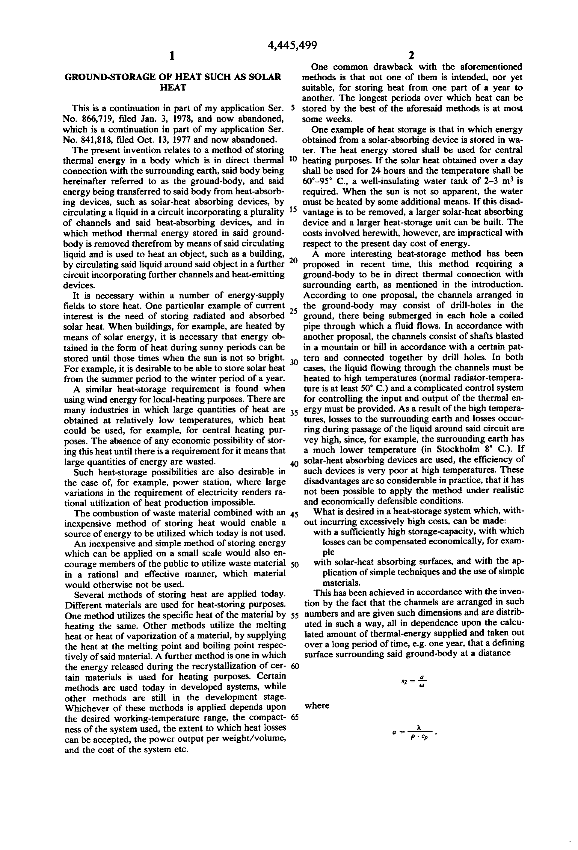
Several methods of storing heat are applied today. This has been achieved in accordance with the inven Different materials are used for heat-storing purposes. tion by the fact that the channels are arranged in such One method utilizes the specific heat of the material by 55 numbers and are given such dimensions and are distrib heating the same. Other methods utilize the melting uted in such a way, all in dependence upon the calcu heat or heat of vaporization of a material, by supplying lated amount of thermal-energy supplied and taken out the heat at the melting point and boiling point respec over a long period of time, e.g. one year, that a defining tively of said material. A further method is one in which surface surrounding said ground-body at a distance the energy released during the recrystallization of cer tain materials is used for heating purposes. Certain - d-
methods are used today in developed systems, while other methods are still in the development stage.
Whichever of these methods is applied depends upon where the desired working-temperature range, the compact 65 ness of the system used, the extent to which heat losses can be accepted, the power output per weight/volume, and the cost of the system etc.
Page 6
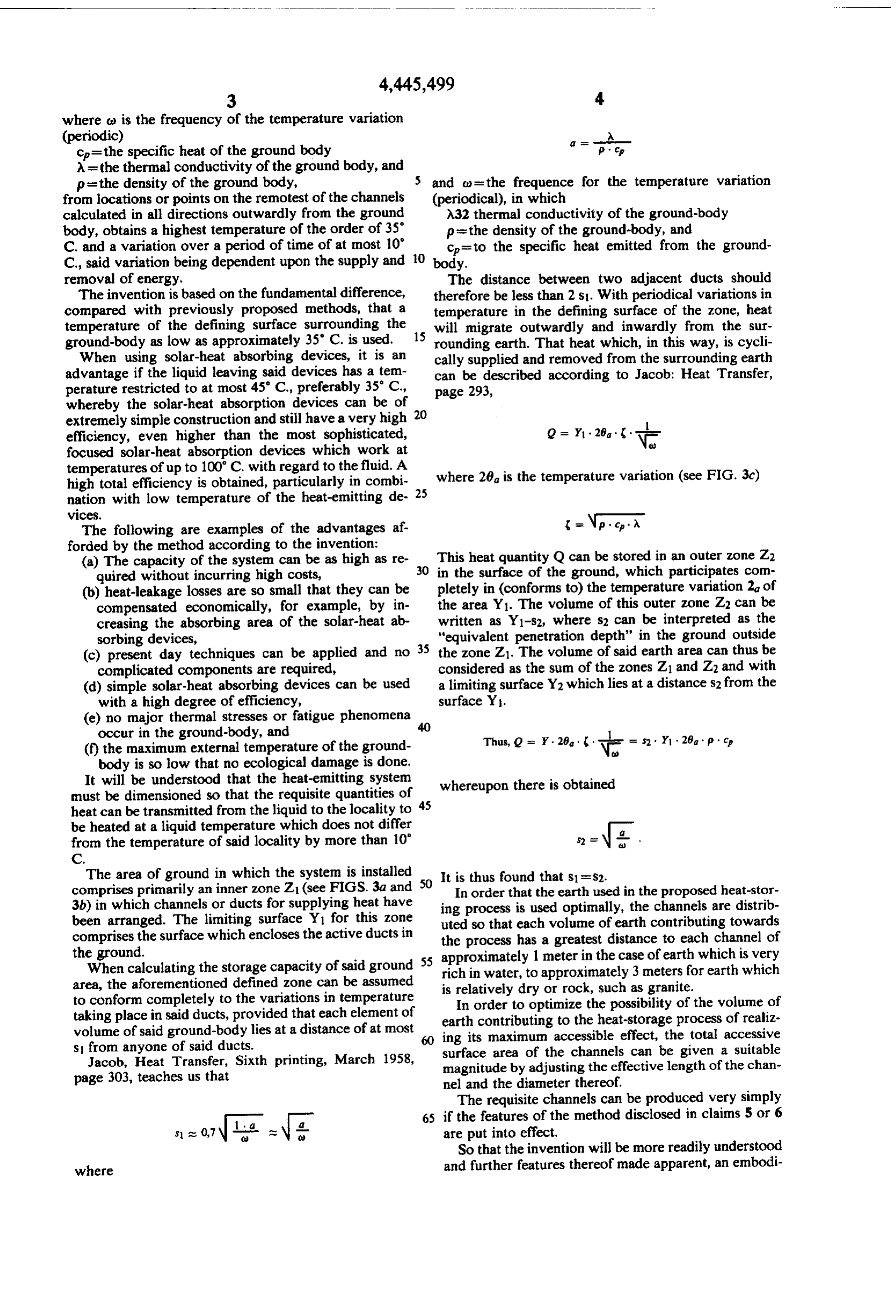
where a) is the frequency of the temperature variation (periodic) E c=the specific heat of the ground body P op A = the thermal conductivity of the ground body, and p = the density of the ground body, 5 and c= the frequence for the temperature variation from locations or points on the remotest of the channels (periodical), in which calculated in all directions outwardly from the ground A32 thermal conductivity of the ground-body body, obtains a highest temperature of the order of 35' p = the density of the ground-body, and C. and a variation over a period of time of at most 10 10 c=to the specific heat emitted from the ground C., said variation being dependent upon the supply and body.
removal of energy. The distance between two adjacent ducts should The invention is based on the fundamental difference, therefore be less than 2 s. With periodical variations in compared with previously proposed methods, that a temperature in the defining surface of the zone, heat temperature of the defining surface surrounding the will migrate outwardly and inwardly from the sur ground-body as low as approximately 35 C. is used. 15 rounding earth. That heat which, in this way, is cycli When using solar-heat absorbing devices, it is an cally supplied and removed from the surrounding earth advantage if the liquid leaving said devices has a tem can be described according to Jacob: Heat Transfer, perature restricted to at most 45' C., preferably 35° C., page 293, whereby the solar-heat absorption devices can be of 20 extremely simple construction and still have a very high 1 efficiency, even higher than the most sophisticated, Q = Y . 28 . . . focused solar-heat absorption devices which work at temperatures of up to 100 C. with regard to the fluid. A high total efficiency is obtained, particularly in combi 25 where 28 is the temperature variation (see FIG. 3c) nation with low temperature of the heat-emitting de
VCCS.
The following are examples of the advantages af = N. . . . forded by the method according to the invention:
(a) The capacity of the system can be as high as re 30 This heat quantity Q can be stored in an outer zone Z2 quired without incurring high costs, in the surface of the ground, which participates com (b) heat-leakage losses are so small that they can be pletely in (conforms to) the temperature variation 2a of compensated economically, for example, by in the area Y1. The volume of this outer zone Z2 can be creasing the absorbing area of the solar-heat ab written as Y1-s2, where s2 can be interpreted as the sorbing devices, "equivalent penetration depth' in the ground outside (c) present day techniques can be applied and no 35 the zone Z1. The volume of said earth area can thus be complicated components are required, considered as the sum of the zones Z1 and Z2 and with (d) simple solar-heat absorbing devices can be used a limiting surface Y2 which lies at a distance s2 from the with a high degree of efficiency, surface Y.
(e) no major thermal stresses or fatigue phenomena occur in the ground-body, and (f) the maximum external temperature of the ground Thus, Q = r. 20. N. s2. Y1, 28a p. c. body is so low that no ecological damage is done.
It will be understood that the heat-emitting system must be dimensioned so that the requisite quantities of 45 whereupon there is obtained heat can be transmitted from the liquid to the locality to be heated at a liquid temperature which does not differ 2 from the temperature of said locality by more than 10 S2 =
The area of ground in which the system is installed It is thus found that s1 =s2.
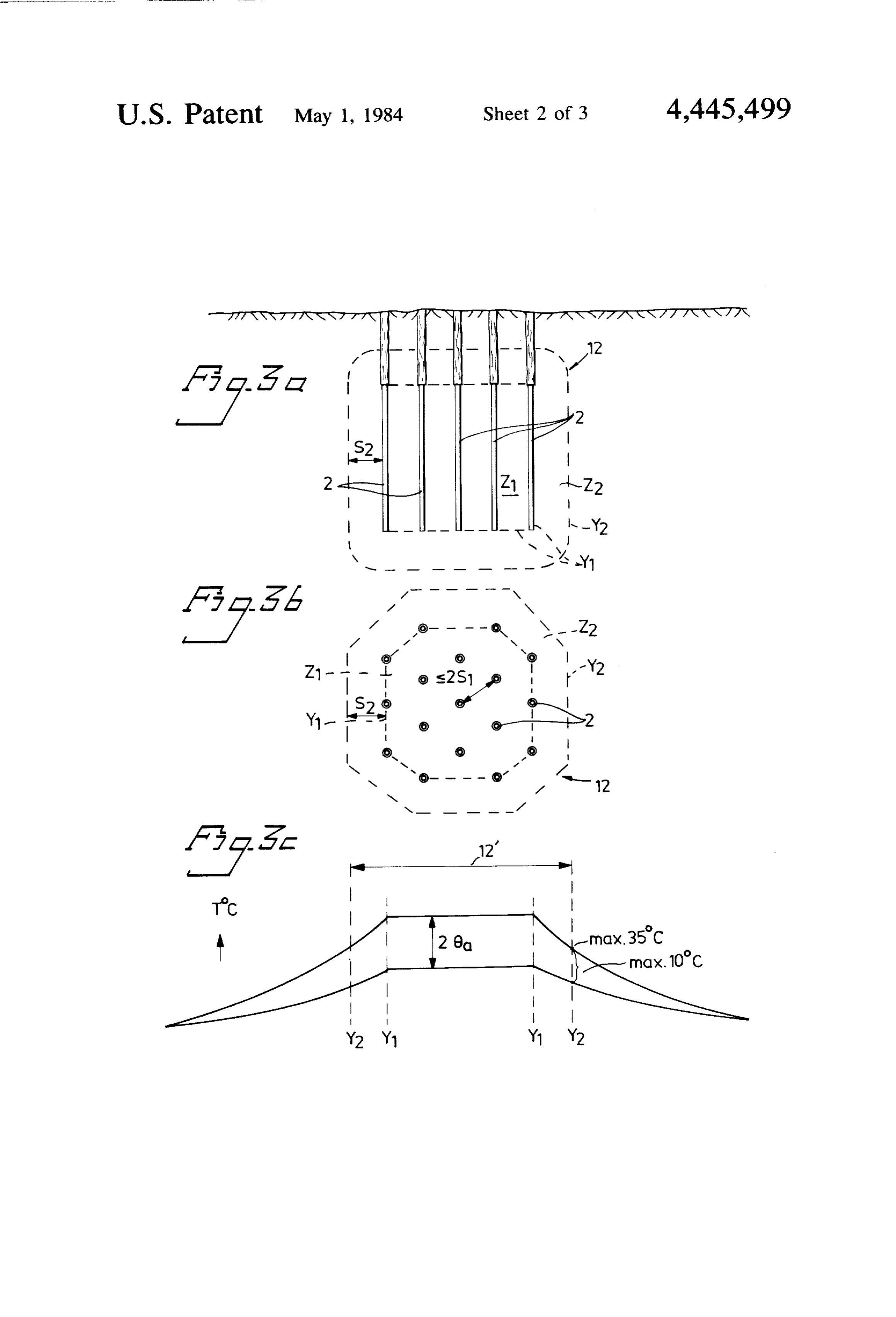
comprises primarily an inner zone Z1 (see FIGS. 3a and 50 In order that the earth used in the proposed heat-stor 3b) in which channels or ducts for supplying heat have ing process is used optimally, the channels are distrib been arranged. The limiting surface Y for this zone uted so that each volume of earth contributing towards comprises the surface which encloses the active ducts in the process has a greatest distance to each channel of the ground. 55 approximately 1 meter in the case of earth which is very When calculating the storage capacity of said ground rich in water, to approximately 3 meters for earth which area, the aforementioned defined zone can be assumed is relatively dry or rock, such as granite. to conform completely to the variations in temperature In order to optimize the possibility of the volume of taking place in said ducts, provided that each element of earth contributing to the heat-storage process of realiz volume of said ground-body lies at a distance of at most 60 ing its maximum accessible effect, the total accessive s from anyone of said ducts.
Jacob, Heat Transfer, Sixth printing, March 1958, surface area of the channels can be given a suitable magnitude by adjusting the effective length of the chan page 303, teaches us that nel and the diameter thereof. The requisite channels can be produced very simply 65 if the features of the method disclosed in claims 5 or 6 s as 0,7 are put into effect.
So that the invention will be more readily understood where and further features thereof made apparent, an embodi
Page 7
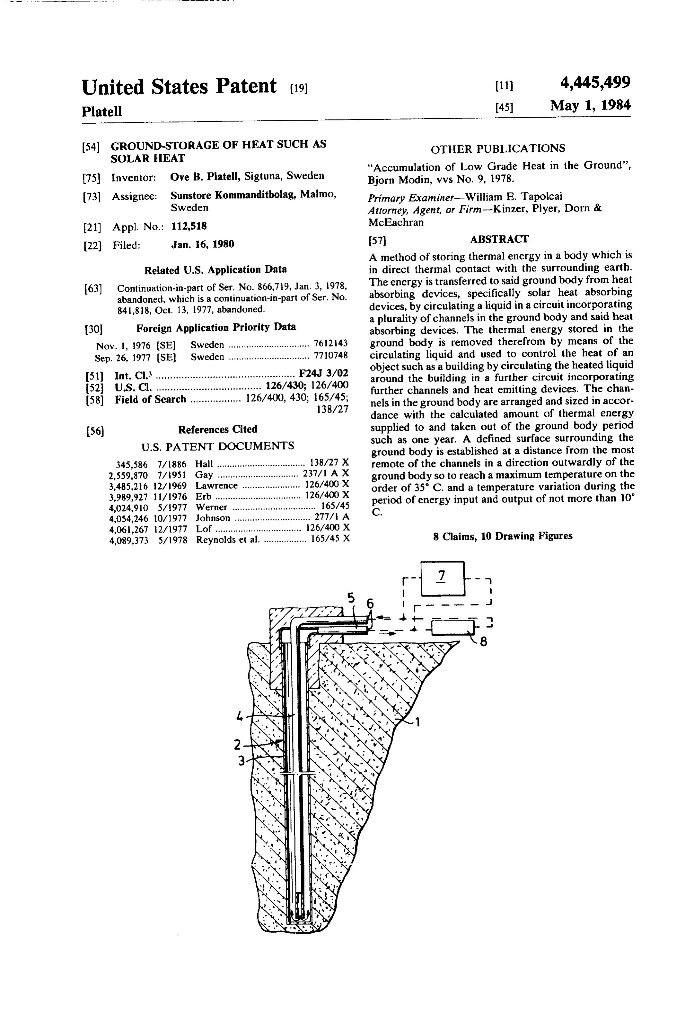
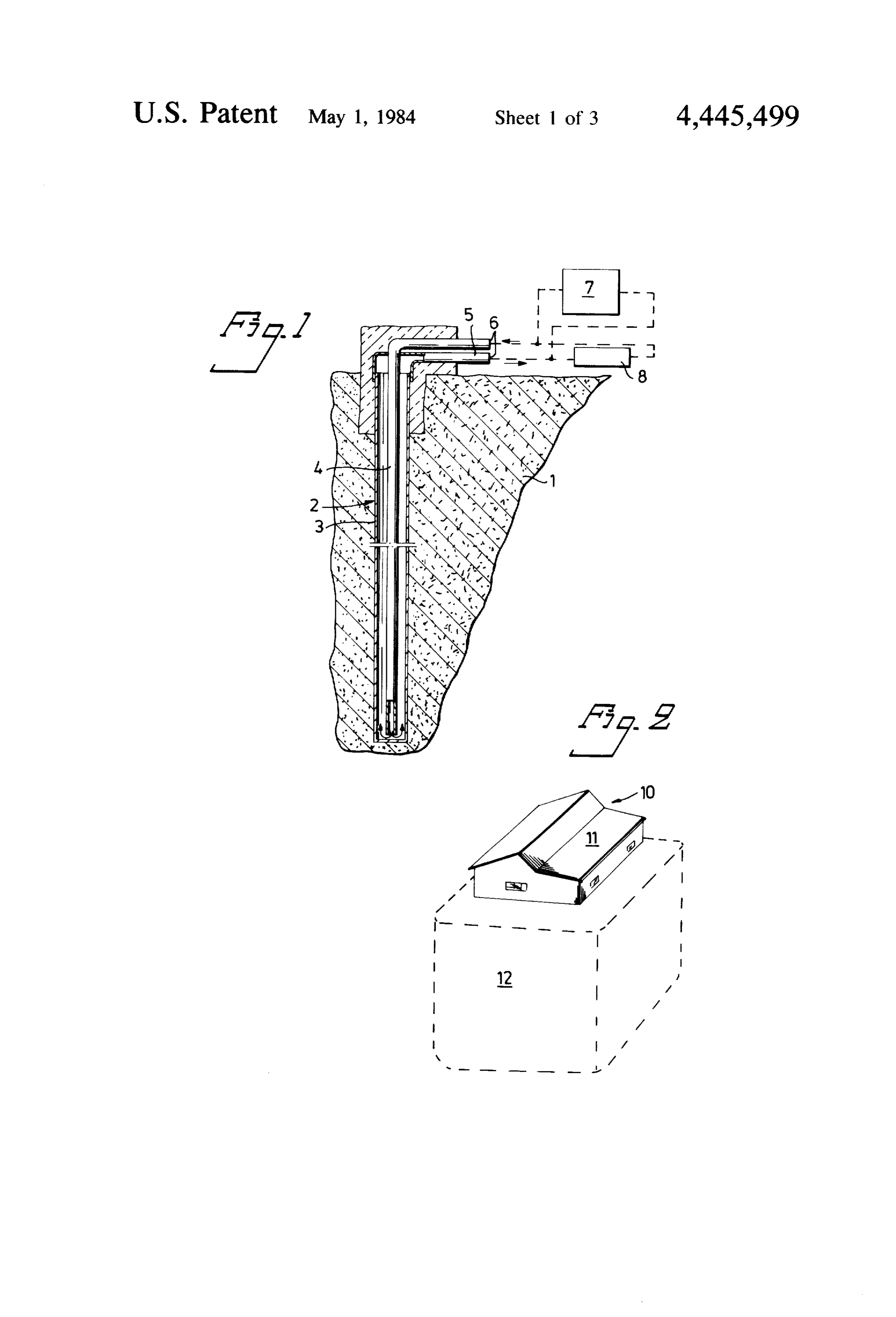
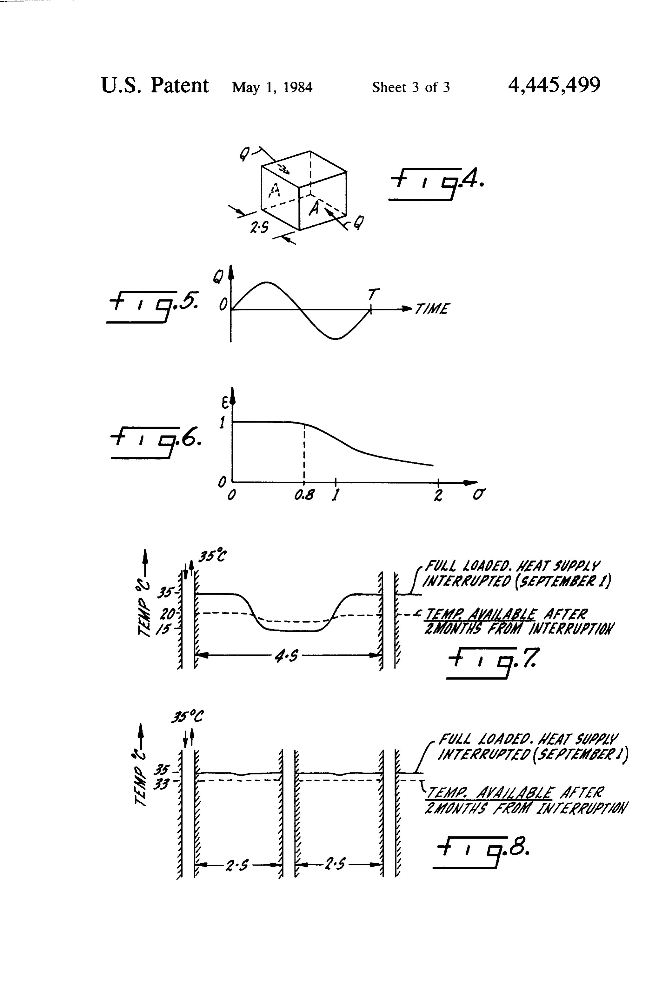
ment of the invention will now be described with refer stood, the drill holes need not be vertical but can be ence to the accompanying drawings, in which inclined to the horizontal if such is required. The FIG. 1 illustrates an embodiment of a simple ducting ground-body extends (granite) approximately 3 meters system created by means of drill holes, outwardly from the two rows of drill holes, both later FIG. 2 illustrates schematically a ground-body lo ally and downwardly (and also upwardly if the upper cated beneath a house and participating in a heat-stor parts of the drill holes shall be insulated) and includes a age system according to the invention, volume >2300 m.
FIGS, 3a and 3b illustrate schematically a ground FIG. 3a illustrates a vertical section through a body in two different views, ground-body 12 formed by five rows of vertical chan FIG. 3c illustrates the area of the variations in tem 10 nels or ducts 2. A limiting surface Y, embraces the perature through a section of the ground-body, channels 2 and passes through the remotest channels FIG. 4 is a schematic representation of a cubic body and their end surfaces. The distances between the chan of earth, nels is at most the distance s1 and the zone enclosed by FIG. 5 is a graph of a time-temperature curve, the limiting surface Y is designated Z1. FIG. 6 is a graph showing the ratio of heat utilization 15 Extending around the zone Z1 is a zone Z2 which has in the body of earth, an extension s2 out to a limiting surface Y2. These zones FIG. 7 is a schematic showing of the temperature and surfaces are shown in plan view in FIG. 3b, drop in a body of earth during withdrawal over a period FIG, 3c illustrates the temperature distribution within of time when the heat ducts are spaced apart too great the extension 12 of the ground-body in a horizontal a distance; and plane and the swing in temperature when supplying FIG. 8 is a schematic showing of the temperature heat energy to the ground and removing energy there drop in a body of earth during withdrawal over a period from by a magnitude of 26. The position of the limiting of time when the heat ducts are spaced apart in accor surfaces Y and Y shown in FIGS. 3a and b are indi dance with the teachings of this invention. cated in FIG. 3c, as is also the temperature distribution FIG. 1 illustrates a channel or ducting path in a 25 externally of the outer limiting surface Y2. ground-body 1, said ducting path comprising an initial In order to increase the temperature of the ground bore of 3 meters length and, for example, a 10 meter body to, for example, a level of 25' C. and 30' C., there deep hole 2 having a diameter of, for example, 2.5 cm., is required initially a relatively large quantity of energy. this hole being lined with a hose 3 of, for example, This energy can be obtained, for example, by temporary aluminum foil to form a conduit, in which a pipe 4 is 30 solar-heat absorbing devices erected on the building arranged concentrically therein. The lining 3, which has site. Obviously, solar-heat absorbing devices are not the been pressed into abutment with the sides of the hole 2, only devices which can be used for this purpose, but is sealingly connected with a pipe 5 which, similarly to that other heat sources can be envisaged. Whatever the pipe 4, is connected to a further pipe 6. These pipes device is used, the cost initially must be considered an together with a heat-supply means 7, for example, a 35 investment. - solar-heat absorbing means, and a heat emitting means In a manner similar to that described with reference 8, for example a radiator, form a closed circuit for a to a conventional house, a high-rise flat can be heated liquid, such as water. by means of, for example, solar-heat absorbing devices In order for the temperature of the earth not to be in conjunction with a ground-body, as hereinbefore unduly affected by the heat-storage system, the upper described, for supplying the block with low-tempera part of the conduit is insulated along a distance marked ture heating facilities. Economic gains can naturally be S2. had by covering to 100% the heat requirements of a The drill holes 2 are placed apart by a distance of at multi-story flat in this way.
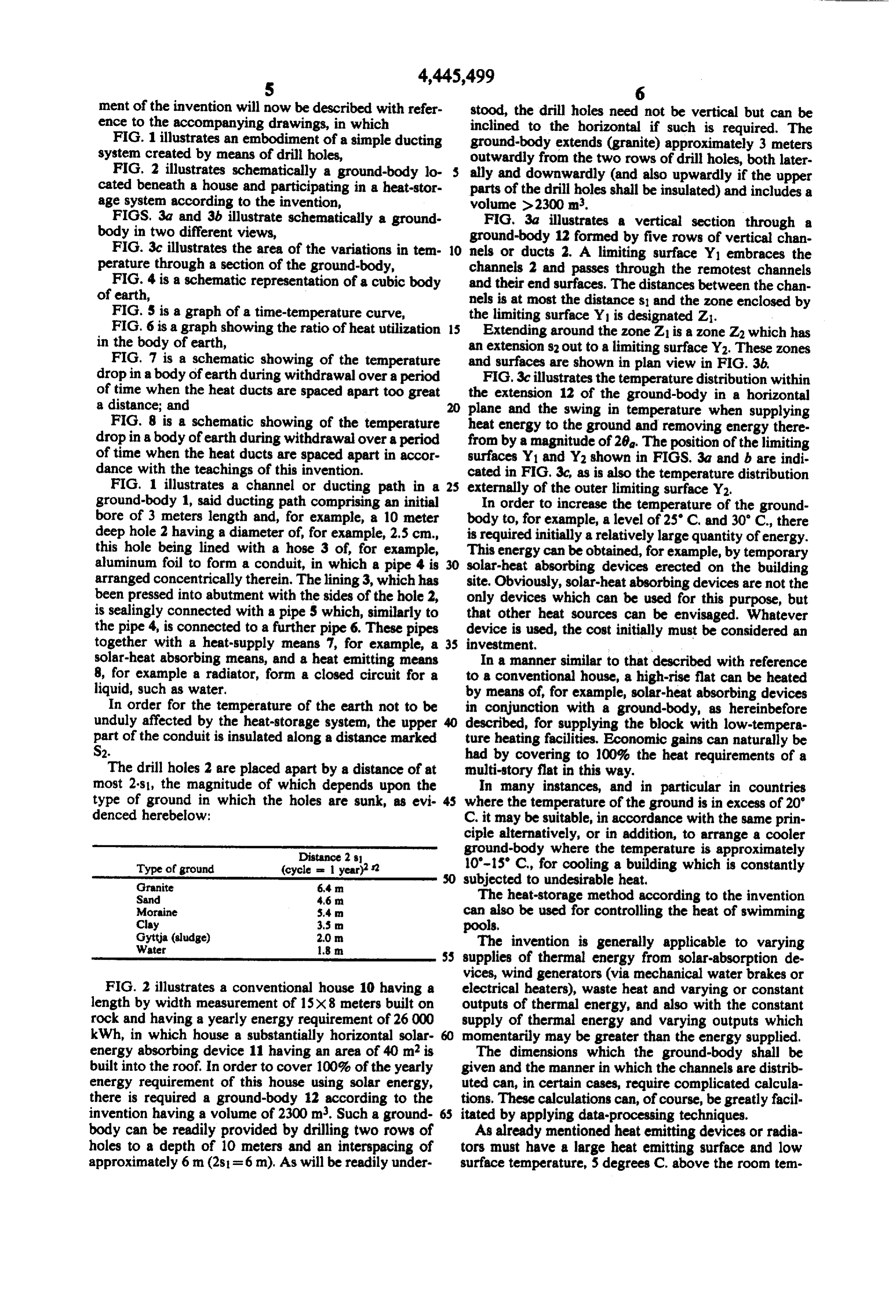
most 2-si, the magnitude of which depends upon the In many instances, and in particular in countries type of ground in which the holes are sunk, as evi where the temperature of the ground is in excess of 20' denced herebelow: C. it may be suitable, in accordance with the same prin ciple alternatively, or in addition, to arrange a cooler
Distance 2 is ground-body where the temperature is approximately
Type of ground (cycle = 1 year)? 10'-15' C., for cooling a building which is constantly Granite 6.4 m subjected to undesirable heat.
Sand 4.6 m The heat-storage method according to the invention Moraine S.4 m can also be used for controlling the heat of swimming Clay
Gyttja (sludge)
pools,
Water 1.8 m. The invention is generally applicable to varying SS supplies of thermal energy from solar-absorption de vices, wind generators (via mechanical water brakes or
FIG. 2 illustrates a conventional house 10 having a electrical heaters), waste heat and varying or constant length by width measurement of 15x8 meters built on outputs of thermal energy, and also with the constant rock and having a yearly energy requirement of 26 000 supply of thermal energy and varying outputs which kWh, in which house a substantially horizontal solar momentarily may be greater than the energy supplied. energy absorbing device 11 having an area of 40 m is The dimensions which the ground-body shall be built into the roof. In order to cover 100% of the yearly given and the manner in which the channels are distrib energy requirement of this house using solar energy, uted can, in certain cases, require complicated calcula there is required a ground-body 12 according to the tions. These calculations can, of course, be greatly facil invention having a volume of 2300 m. Such a ground- 65 itated by applying data-processing techniques. body can be readily provided by drilling two rows of As already mentioned heat emitting devices or radia holes to a depth of 10 meters and an interspacing of tors must have a large heat emitting surface and low approximately 6 m (2s1=6 m). As will be readily under surface temperature, 5 degrees C. above the room tem
Page 8
perature, for example. Such a device may cover one or trating the temperature distribution in the ground-body more wall surfaces or ceiling surfaces of a room. The between adjacent channels spaced the distance 4-s and heat emitting surface may consist, for example, of a thin 2s, respectively.
board panel behind which air of a temperature of about The invention is not restricted to the described and 25 degrees C. is slowly flowing. The air is heated by illustrated embodiments, but can be modified within the tubes arranged across the air flow direction and behind scope of the accompanying claims. the panel. The tubes carry the circulating liquid, which I claim:
has a temperature of 27 degrees C. for example. A por 1. A method of arranged a ground-body in the earth tion of the flowing air may consist of fresh air supplied for storing thermal energy in said ground-body which is by a small fan. Also the heat absorbing devices can be O in direct thermal connection with the surrounding constructed in the same simple manner even if a more earth, said energy being transferred to said body from weather resistant panel is to be used, an aluminum plate heat-absorbing devices, such as thermal-heat absorbing for example. devices, by circulating a liquid in a circuit incorporating An explanation of the usefulness of this invention is as a plurality of channels and said heat-absorbing devices, follows: 15
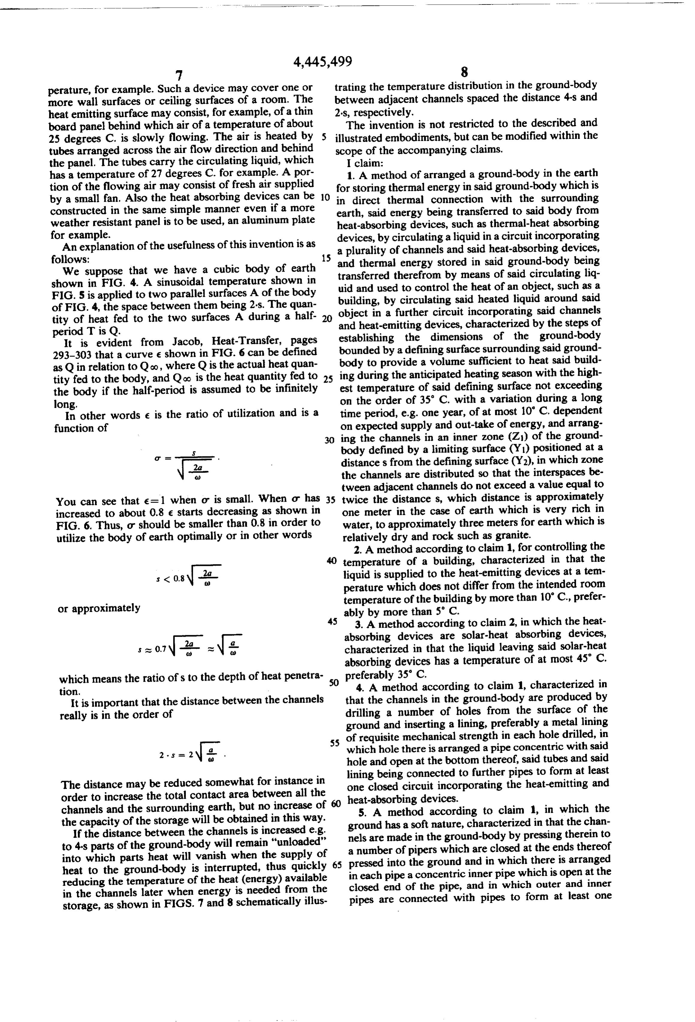
We suppose that we have a cubic body of earth and thermal energy stored in said ground-body being shown in FIG. 4. A sinusoidal temperature shown in uid and usedtherefrom transferred by means of said circulating liq to control the heat of an object, such as a
FIG. 5 is applied to two parallel surfaces A of the body building, by circulating said heated liquid around said of FIG. 4, the space between them being 2-s. The quan object in a further circuit incorporating said channels tity of heat fed to the two surfaces. A during a half 20 and heat-emitting devices, characterized by the steps of period T is Q.
It is evident from Jacob, Heat-Transfer, pages bounded by a defining surface surroundingground-body establishing the dimensions of the said ground 293-303 that a curve e shown in FIG. 6 can be defined as Q in relation to Qoo, where Q is the actual heat quan ing during the anticipated heating season withsaid body to provide a volume sufficient to heat build the high tity fed to the body, and Qoo is the heat quantity fed to 25 the body if the half-period is assumed to be infinitely est temperature of said defining surface not exceeding long. on the order of 35° C. with a variation during a long In other words e is the ratio of utilization and is a time period, e.g. one year, of at most 10 C. dependent function of on expected supply and out-take of energy, and arrang 30 ing the channels in an inner zone (Z) of the ground body defined by a limiting surface (Y) positioned at a distances from the defining surface (Y2), in which zone the channels are distributed so that the interspaces be tween adjacent channels do not exceed a value equal to
You can see that e = 1 when or is small. When or has 35 twice the distances, which distance is approximately increased to about 0.8 e starts decreasing as shown in one meter in the case of earth which is very rich in FIG. 6. Thus, or should be smaller than 0.8 in order to water, to approximately three meters for earth which is utilize the body of earth optimally or in other words relatively dry and rock such as granite. 2. A method according to claim 1, for controlling the temperature of a building, characterized in that the
2a liquid is supplied to the heat-emitting devices at a tem perature which does not differ from the intended room temperature of the building by more than 10 C., prefer or approximately ably by more than 5 C.
45 3. A method according to claim 2, in which the heat absorbing devices are solar-heat absorbing devices,
s at 0.7 ar characterized in that the liquid leaving said solar-heat absorbing devices has a temperature of at most 45 C.
which means the ratio of s to the depth of heat penetra- 50 preferably 35° C.
tion. 4. A method according to claim 1, characterized in It is important that the distance between the channels that the channels in the ground-body are produced by really is in the order of drilling a number of holes from the surface of the ground and inserting a lining, preferably a metal lining
S5 of requisite mechanical strength in each hole drilled, in which hole there is arranged a pipe concentric with said 2. - hole and open at the bottom thereof, said tubes and said lining being connected to further pipes to form at least
The distance may be reduced somewhat for instance in one closed circuit incorporating the heat-emitting and order to increase the total contact area between all the 60 heat-absorbing devices.
channels and the surrounding earth, but no increase of 5. A method according to claim 1, in which the the capacity of the storage will be obtained in this way. ground
If the distance between the channels is increased e.g. nels are has a soft nature, characterized in that the chan made in the ground-body by pressing therein to to 4's parts of the ground-body will remain "unloaded" into which parts heat will vanish when the supply of 65 apressed number of pipers which are closed at the ends thereof into the ground and in which there is arranged heat to the ground-body is interrupted, thus quickly in each pipe a concentric inner pipe which is open at the reducing the temperature of the heat (energy) available closed end of the pipe, and in which outer and inner in the channels later when energy is needed from the pipes are connected with pipes to form at least one storage, as shown in FIGS. 7 and 8 schematically illus
Page 9
closed circuit incorporating the heat-emitting and heat three (3) meters in earth which is relatively dry and absorbing devices. rock such as granite, 6. A method of establishing a heat-storage zone in the providing a liquid conduit between said heat-absorb earth which can be supplied with heat from heat ing devices, said heat-emitting devices and said absorbing means during one season of the year and from 5 channels, and which heat can be taken in another season of the year circulating said liquid between said heat-absorbing for distribution to heat-emitting means in a building or devices and said channels during one season of the similar structure with the heat storage zone having year to store heat in said heat storage zone and sufficient capacity to store all of the heat necessary for circulating said fluid between said channels and the building during said another season without raising 10 said heat-emitting devices during another season of the temperature at the periphery of the storage zone in the year to remove heat from said heat storage the earth above about 35 C, with the variation of the ZOne.
temperature at the periphery of the storage zone not to 7. The method of claim 1 in which the channels in exceed 10 C. during the year, said method including clude bores drilled in the earth and pipe inserted in the the steps of: 5 bores to form part of the circuit including the heat ab forming a plurality of channels in the earth with the sorbing devices, with the pipe being introduced into the channels spaced a distances from the periphery of bores from the surface of the ground-body. 8. The method of claim 7 in which the bores are lined the storage zone and a distance not exceeding 2s from one another, with aluminum foil and the pipes are inserted in the said distances being approximately one (l) meter in 20 bores inwardly of the aluminum foil st lining.
the case of earth rich in water to approximately
Provenance
- Collection
- Cited prior art
- Original PDF
- patentimages.storage.googleapis.com →
- Filed
- 1980-01-16
- Pages
- 9
- Method
- pdftotext (the PDF's own text layer) + pdftoppm 300dpi page scans
- Source
- Google Patents bibliographic record
- Granted
- 1984-05-01
- Inventors
- Ove B. Platell; SUNSTORE KB
- Transcribed from
- patentimages.storage.googleapis.com →