patent · US4240268
Ground cold storage and utilization
23 December 1980
Page 1 — bibliographic record
United States Patent (19) 11) 4,240,268 Yuan 45 Dec. 23, 1980 54 GROUND COLD STORAGE AND 4,111, 89 9/1978 Dizon ................................... 126/400 UTHLIZATION Primary Examiner-Lloyd L. King 76) Inventor: Shao W. Yuan, 6701 Montour Dr., (57) ABSTRACT Falls Church, Va. 22043
A system for transmitting, storing and utilizing cold 21 Appl. No.: 951,518 which includes the use of heat pipes for transmitting the 22 Filed: Oct. 13, 1978 winter cold to freeze the ground water storage, and 51 Int. Cl. ......................... A25D 23/12, F24H 7/oo two-phase flow pipes to effectively cool the warm air 52 U.S. Cl. ....................................... 62/360; 126/400 passing through the flow pipes in the air conditioning 58) Field of Search .................... 62/260, 119. 165/45, duct. The system provides for long-duration earth stor 60/0.5. 126/400 age of the winter cold which can be effectively used during summer seasons for cooling homes, buildings 56) References Cited and other structures.
Re. 26,387 5/1968 Balch ..................................... 62/222 irreversible vapor flow, include a pump arrangement 3,195,619 7/1965 Tippmann ... 62/19 for transferring working fluid from the condenser sec 3,472,314 10/1969 Balch ....... tr. 92/26 tion to the evaporator section of the flow pipes where is: A2; Rio - - - - - 12(58. phase-change is taken place by absorbing heat from the 4,011,736 3/977 Harrison . 62/260 passing warm air.
4,042,012 8/1977 Perry ....... ... 62/26O 4,091,636 5/1978 Margen .................................. 165/45 11 Claims, 3 Drawing Figures
IO, 54 k -N
22s22saxxaaz zzyzzé | s : so K.
a --22
YS es s
ls. s 59
Page 2
Drawing sheet — no readable text.
Page 3
Drawing sheet — no readable text.
Page 4
roundings above the ground into underground water
GROUND COLD STORAGE AND UTILIZATION tank may be used if required.
BACKGROUND OF THE INVENTION
The extraction of cold from the cold storage for space cooling is accomplished by pumping cold liquid 1. Field of the Invention through a closed piping loop. When air conditioning is The present invention relates to utilizing winter cold in operation the cold liquid is pumped from the piping more particularly to transmitting and storing winter loop in the cold storage to a bank of two-phase flow cold underground for effective uses during summer pipes situated in the ventilation air duct. The two-phase SeaSOS.
2. Description of the Prior Art O flow pipe is equivalent to the vaporator section of a heat Prior art ground cold storage systems are generally pipe. As the returning warm air from rooms or other accomplished by blowing winter cold ambient air to environment passes through the two-phase flow pipes in pass through the cold reservoir formed by crushed the ventilation air duct, it loses heat to the coolant in the stones and rock beds. In other cases, cold liquid medium 15 pipes so that the liquid in the wick of the pipe vaporizes. is pumped through pipes embedded in stone and rock The vaporized working fluid then flows downwardly medium in the form of which constitutes a closed heat through the piping loop to the cold storage tank where exchange system. the vapor condenses. The condensed vapor or cold The stones and rocks, as a cold storage reservoir, liquid is again pumped back to the bank of two-phase have several shortcomings. First, cold storage capaci flow pipes. As mentioned previously, the phase change ties are limited because of the narrow temperature 20 from cold liquid to vapor in the two-phase flow pipes range for cooling. In other words, the difference of requires latent heat of vaporation which is supplied by storage temperature in winter and upperlimit useful the temperatures in summer is less than thirty degrees Fahr the returning warm air in the ventilation air duct. Thus, highly effective means for space cooling described enheit (30 F. to 60 F). For example, in a volume of in this invention is evident.
one cubic foot of stone at a temperature difference of 25 30 F., the energy flux is about 1.3X 10 BTU. Assuming Accordingly, an important object of the invention is a summer requirement of 25x100 BTU for an average to provide for long-duration underground storage of size home, a volume of cold storage required for cool winter cold which can be used for space cooling in ing is estimated at 20x10 cubic feet. In contrast to this 30 homes and buildings, etc., when air conditioning is re large volume, if ice is used for cold storage instead of quired, without relying on energy from fossil fuel such rock, the required storage volume is about 2.5X 10³ as conventional air conditioning units. cubic feet. Another important object of the invention is to pro Another shortcoming of the stone and rocks as cold vide a highly efficient means for transmitting cold from storage is the low thermal conductivity. It would re quire a long length of liquid pipes and considerable 35 the subfreezing atmosphere or environment into the ground for cold storage through the use of heat pipes pumping power in order to meet the maximum cooling rate required during hot summer days. without the aid of energy consumption pumps and ther mostatic control.
SUMMARY OF THE INVENTION A further and important object of the invention is to The present invention relates to a system for transmit provide means to freeze water in the cold storage; ting, storing and utilizing winter cold, and more partic thereby a considerable storage volume can be reduced ularly, to a system in which winter cold can be stored for the same cold storage capacity. underground for subsequent cooling utilization during A still further important object of the invention is to summers without relying on conventional air-condition provide an efficient means for transferring cold from
The invention contemplates a novel system for trans storage flow for space cooling through the use of two-phase pipes including an evaporator section placed inside mitting, storing and utilizing cold wherein the system comprises means for transmitting the winter cold above the ventilation air duct and a condenser section placed ground to freeze water in a reservoir below the surface in the cold storage, and pump means for transferring the of the ground, and circulation means to circulate the 50 cold liquid, after phase change from vapor to liquid, stored cold to the ventilation air duct which cools and from the condenser section to the evaporator section. dehumidifies the returning warm air flow from the A still further object of the invention is to provide space cooling in an air-conditioning system. means to utilize the latent heat of evaporation required For accomplishing the foregoing objective, the in for phase change of the liquid in the two-phase flow vention contemplates the use of heat pipes for transmis 55 pipes to efficiently cool the returned warm air from sion of the winter cold to an underground water tank. space cooling in the ventilation air duct of the air-condi The water in the tank is cooled and finally frozen during tioning system.
the winter season. Since the condenser section of the heat pipe is above the surface of the ground and the very A still further object of the invention is to provide a evaporator section is below, neither pump nor thermo compressor
quiet air-conditioning system which is free from stat control is required for this system. Furthermore, noise.
since the latent heat of vaporization required to change A still further object of the invention is to provide an the cold liquid (antifreeze) to vapor in the evaporator economical air-conditioning system which is almost section of the heat pipe is about seven times greater than free from maintenance and utility costs. the heat of fusion delivered by converting water to ice, 65 Further objects and advantages of my invention will the proposed system for establishing ice storage is tech become apparent from an understanding of the follow nically most efficient. However, alternative means by ing detailed description of preferred embodiments of circulating antifreeze through pipes from cold sur my invention.
Page 5
DESCRIPTION OF THE DRAWINGS coolant to vaporize, as indicated by the arrow 60. The vapor then flows under pressure downwardly through
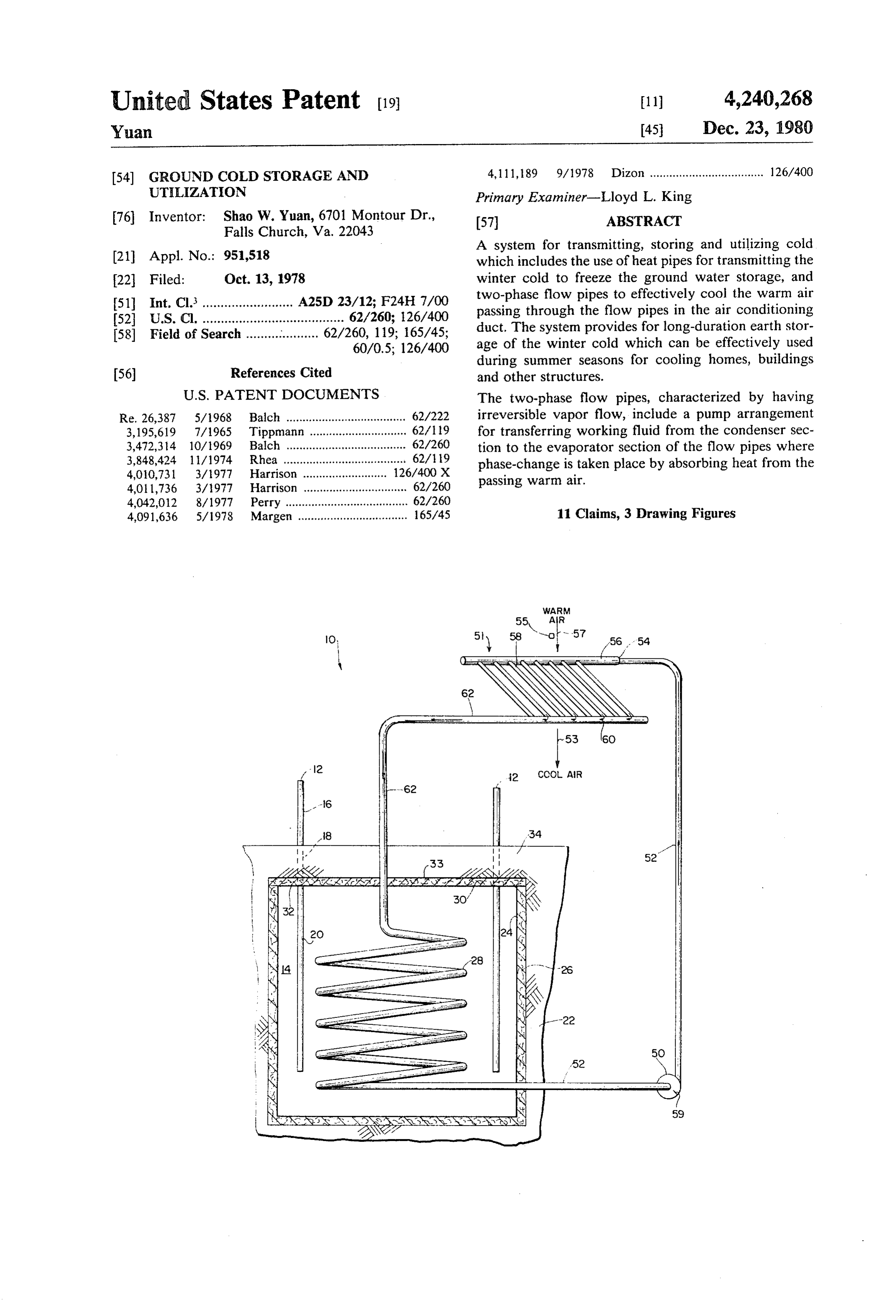
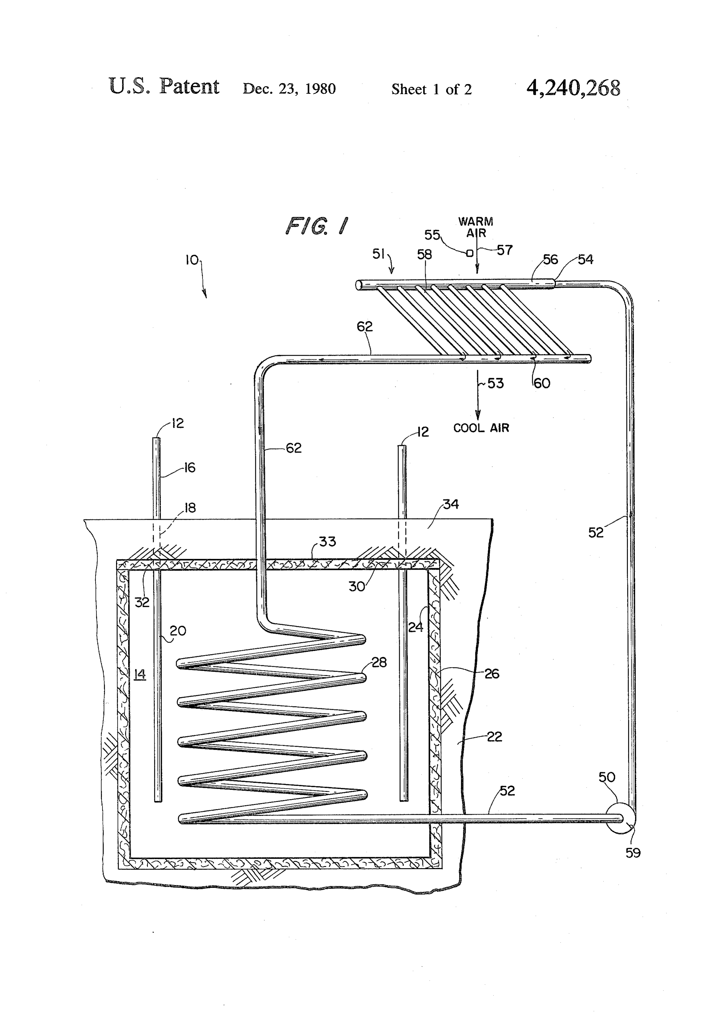
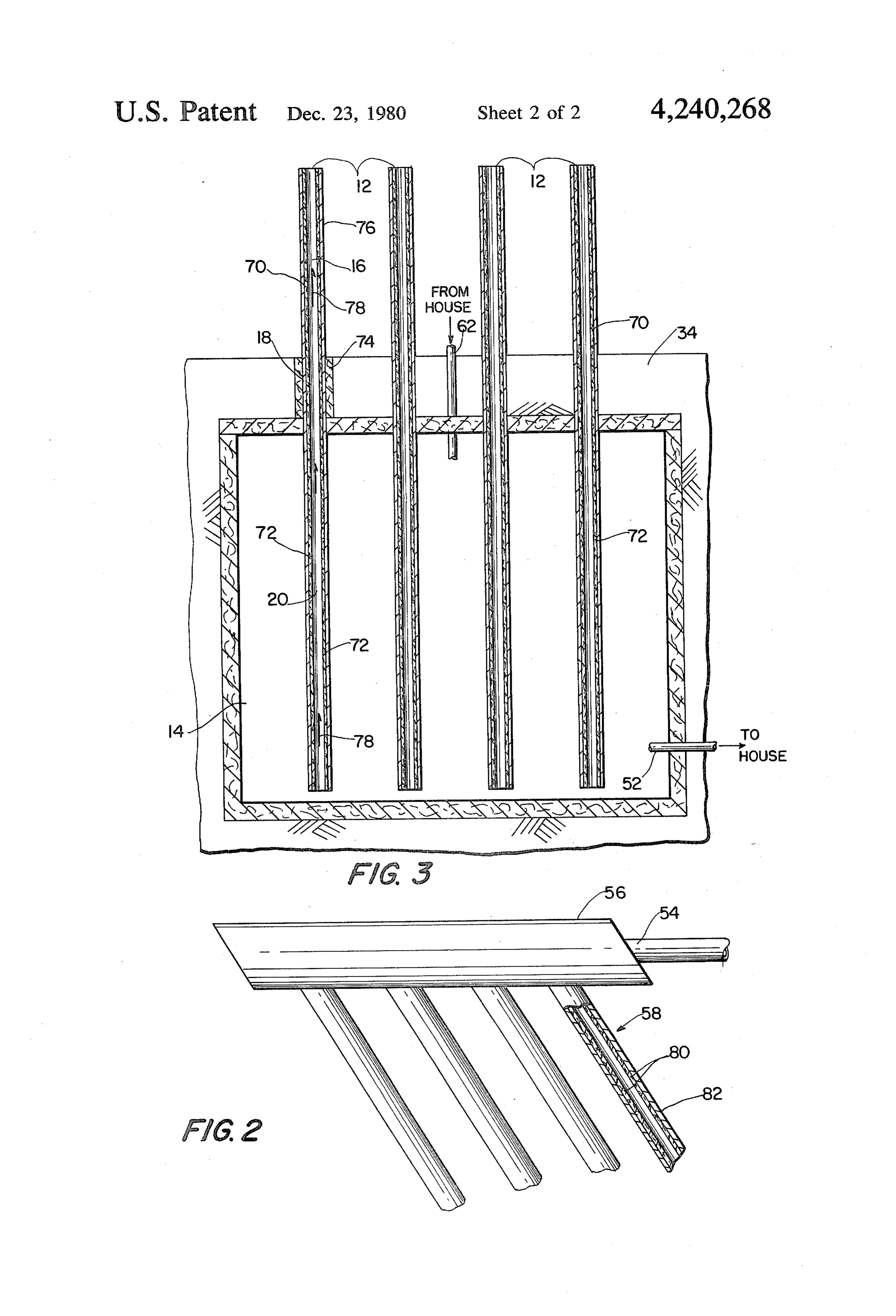
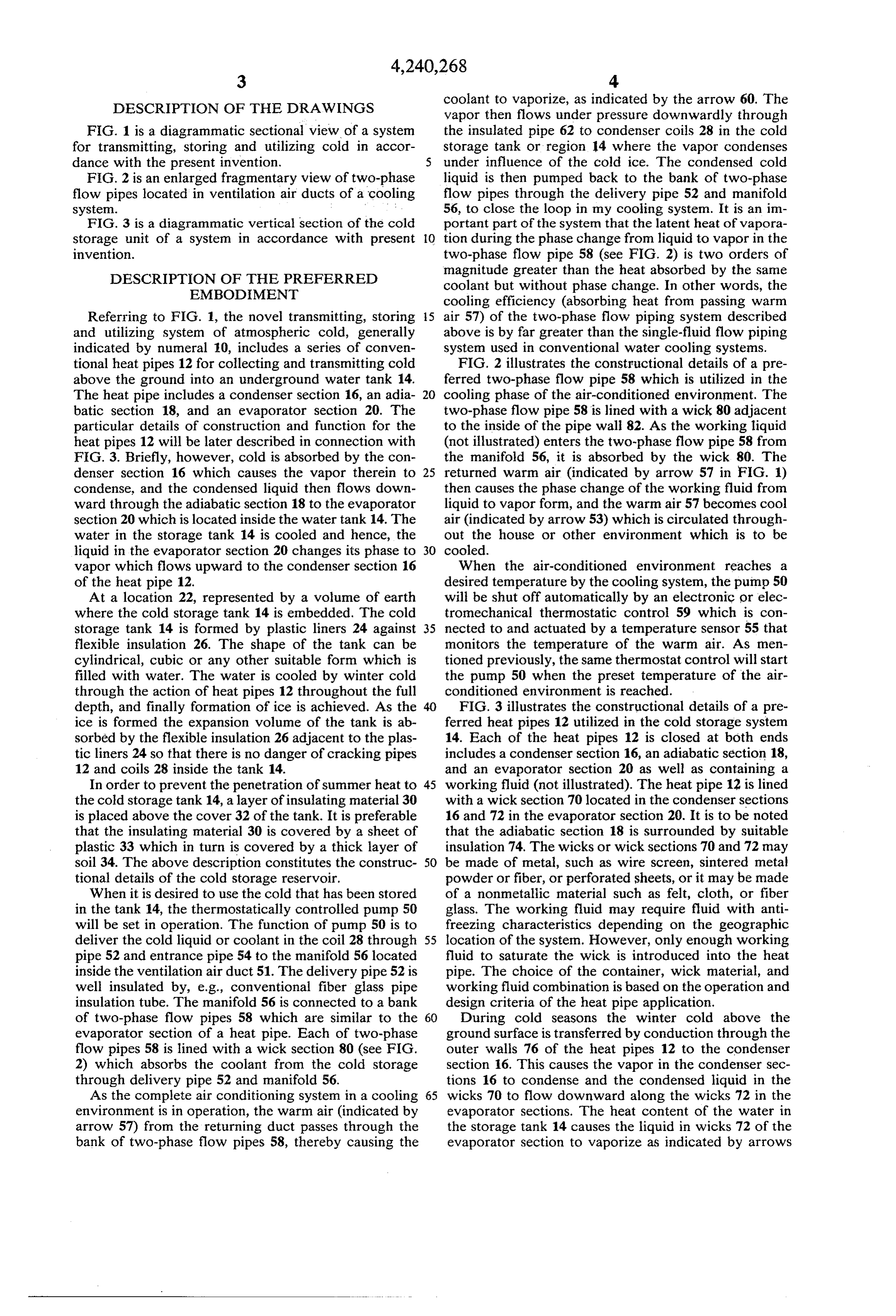
FIG. 1 is a diagrammatic sectional view of a system the insulated pipe 62 to condenser coils 28 in the cold for transmitting, storing and utilizing cold in accor storage tank or region 14 where the vapor condenses dance with the present invention. under influence of the cold ice. The condensed cold FIG. 2 is an enlarged fragmentary view of two-phase liquid is then pumped back to the bank of two-phase flow pipes located in ventilation air ducts of a cooling flow pipes through the delivery pipe 52 and manifold system. . . .. . 56, to close the loop in my cooling system. It is an im FIG. 3 is a diagrammatic vertical section of the cold portant part of the system that the latent heat of vapora storage unit of a system in accordance with present 10 tion during the phase change from liquid to vapor in the invention. two-phase flow pipe 58 (see FIG. 2) is two orders of
DESCRIPTION OF THE PREFERRED
magnitude greater than the heat absorbed by the same
EMBODIMENT coolant but without phase change. In other words, the cooling efficiency (absorbing heat from passing warm
Referring to FIG. 1, the novel transmitting, storing 5 air 57) of the two-phase flow piping system described and utilizing system of atmospheric cold, generally above is by far greater than the single-fluid flow piping indicated by numeral 10, includes a series of conven system used in conventional water cooling systems. tional heat pipes 12 for collecting and transmitting cold FIG. 2 illustrates the constructional details of a pre above the ground into an underground water tank 14. ferred two-phase flow pipe 58 which is utilized in the The heat pipe includes a condenser section 16, an adia 20 cooling phase of the air-conditioned environment. The batic section 18, and an evaporator section. 20. The two-phase flow pipe 58 is lined with a wick 80 adjacent particular details of construction and function for the to the inside of the pipe wall 82. As the working liquid heat pipes 12 will be later described in connection with (not illustrated) enters the two-phase flow pipe 58 from FIG. 3. Briefly, however, cold is absorbed by the con the manifold 56, it is absorbed by the wick 80. The denser section 16 which causes the vapor therein to 25 returned warm air (indicated by arrow 57 in FIG. 1) condense, and the condensed liquid then flows down then causes the phase change of the working fluid from ward through the adiabatic section 18 to the evaporator liquid to vapor form, and the warm air 57 becomes cool section 20 which is located inside the water tank 14. The air (indicated by arrow 53) which is circulated through water in the storage tank 14 is cooled and hence, the out the house or other environment which is to be liquid in the evaporator section 20 changes its phase to 30 cooled.
vapor which flows upward to the condenser section 16 When the air-conditioned environment reaches a of the heat pipe 12. desired temperature by the cooling system, the pump 50 At a location 22, represented by a volume of earth will be shut off automatically by an electronic or elec where the cold storage tank 14 is embedded. The cold tromechanical thermostatic control 59 which is con storage tank 14 is formed by plastic liners 24 against 35 nected to and actuated by a temperature sensor 55 that flexible insulation 26. The shape of the tank can be monitors the temperature of the warm air. As men cylindrical, cubic or any other suitable form which is tioned previously, the same thermostat control will start filled with water. The water is cooled by winter cold the pump 50 when the preset temperature of the air through the action of heat pipes 12 throughout the full conditioned environment is reached. depth, and finally formation of ice is achieved. As the 40 FIG. 3 illustrates the constructional details of a pre ice is formed the expansion volume of the tank is ab ferred heat pipes 12 utilized in the cold storage system sorbed by the flexible insulation 26 adjacent to the plas 14. Each of the heat pipes 12 is closed at both ends tic liners 24 so that there is no danger of cracking pipes includes a condenser section 16, an adiabatic section 18, 12 and coils 28 inside the tank 14. and an evaporator section 20 as well as containing a In order to prevent the penetration of summer heat to 45 working fluid (not illustrated). The heat pipe 12 is lined the cold storage tank 14, a layer of insulating material 30 with a wick section 70 located in the condenser sections is placed above the cover 32 of the tank. It is preferable 16 and 72 in the evaporator section 20. It is to be noted that the insulating material 30 is covered by a sheet of that the adiabatic section 18 is surrounded by suitable plastic 33 which in turn is covered by a thick layer of insulation 74. The wicks or wick sections 70 and 72 may soil 34. The above description constitutes the construc 50 be made of metal, such as wire screen, sintered metal tional details of the cold storage reservoir. powder or fiber, or perforated sheets, or it may be made When it is desired to use the cold that has been stored of a nonmetallic material such as felt, cloth, or fiber in the tank 14, the thermostatically controlled pump 50 glass. The working fluid may require fluid with anti will be set in operation. The function of pump 50 is to freezing characteristics depending on the geographic deliver the cold liquid or coolant in the coil 28 through 55 location of the system. However, only enough working pipe 52 and entrance pipe 54 to the manifold 56 located fluid to saturate the wick is introduced into the heat inside the ventilation air duct 51. The delivery pipe 52 is pipe. The choice of the container, wick material, and well insulated by, e.g., conventional fiber glass pipe working fluid combination is based on the operation and insulation tube. The manifold 56 is connected to a bank design criteria of the heat pipe application. of two-phase flow pipes 58 which are similar to the 60 During cold seasons the winter cold above the evaporator section of a heat pipe. Each of two-phase ground surface is transferred by conduction through the flow pipes 58 is lined with a wick section 80 (see FIG. outer walls 76 of the heat pipes 12 to the condenser 2) which absorbs the coolant from the cold storage section 16. This causes the vapor in the condenser sec through delivery pipe 52 and manifold 56. tions 16 to condense and the condensed liquid in the As the complete air conditioning system in a cooling 65 wicks 70 to flow downward along the wicks 72 in the environment is in operation, the warm air (indicated by evaporator sections. The heat content of the water in arrow 57) from the returning duct passes through the the storage tank 14 causes the liquid in wicks 72 of the bank of two-phase flow pipes 58, thereby causing the evaporator section to vaporize as indicated by arrows
Page 6
78 (FIG. 3). As the vapor flows upwardly into the con 2. A system as defined in claim 1 wherein said heat denser sections 16, the subfreezing cold above the pipe includes a condenser section extending into the ground condenses it, and the condensed liquid returns above-ground environment, an evaporator section ex back to the evaporator section through wicks 72. This tending into said substance of said storage means, and an constitutes the cooling and freezing process of the cold 5 adiabatic section connected between said condenser storage reservoir without any aid of energy operated section and said evaporator section.
pumps and controls. 3. A system as defined in claim 1 wherein said storage When the temperature above the ground is higher means includes a plastic liner for containing said sub than the temperature inside the cold storage tank 14, the 10 stance at said location below the surface of the ground. 4. A system as defined in claim 3 wherein said sub operation of the heat pipes 12 would seem to be re stance versed from that operation as described above. How cooled isbywater which changes phase to ice upon being said transmitting means.
ever, in this case the condensed liquid in the sections 20 5. A system as defined in claim 3 including insulation (now functioning as condenser sections) cannot rise up means located about said plastic liner for minimizing against gravity, and the heat pipes would cease to func 15 loss of cold to the surrounding earth and for compensat tion. Hence, there will be no danger on warm days of ing for expansion losing the cold from the storage tank 14 to the warmer change from liquidoftosaid substance caused by a phase solid.
environment around the section 16 of the heat pipes.
While a preferred system and a preferred combina ing6. means A system as defined in claim 1 wherein said utiliz includes two-phase flow pipe means, and tion of heat pipes and two-phase flow pipes for use in 0 means for passing relatively warm air across said flow such system have been illustrated and described, it is to pipes for cooling said air.
be understood that various changes and arrangement of 7. A system as defined in claim 6 wherein said recov parts may be made without departing from the spirit ery means includes a closed-circuit pipe means having a and scope of the invention as defined in the appended first portion thereof surrounded by said substance at claims. 25 said location below the ground, a second portion I claim:
1. A system for extracting, transmitting, storing, re thereof extending from said location to said two-phase flow pipe means for delivering cold liquid thereto, and covering and utilizing cold, said system comprising: a third portion extending from said flow pipes back to a. apparatus for extracting cold from the environ said first portion for delivering vapor from said flow ment; 30 pipes to said first portion.
b. transmitting means for transmitting said cold from 8. A system as defined in claim 7 including pump environment above the ground to a location below means located in said second portion of said closed-cir the surface of the ground; said transmitting means cuit pipe means for pumping said liquid through said comprising a heat pipe, second portion to said two-phase flow pipe means. c. storage means for storing cold, said storage means 35 9. A system as defined in claim 6 wherein said two including a substance which is capable of changing phase flow pipe means include wick means for absorb phase, said substance being located at said location ing liquid.
below the surface of the ground for receiving and 10. A system as defined in claim 6 wherein said flow storing cold transmitting thereto by said transmit pipe means includes a manifold and a plurality of flow ting means; 40 pipes connected to said manifold, each of said flow d. recovery means for recovering cold from said pipes containing wick means therein; and said recovery storage means and delivering it to a second envi means including pump means for pumping liquid from ronment; and said location below the ground to said manifold. e. utilizing means connected to said recovery means 11. A system as defined in claim 10 including a ther for receiving cold therefrom and dispersing said 45 mostat control meansk connectedis sk xk tosk said pump means.
cold throughout said second environment.
Provenance
- Collection
- Cited prior art
- Original PDF
- patentimages.storage.googleapis.com →
- Filed
- 1978-10-13
- Pages
- 6
- Method
- pdftotext (the PDF's own text layer) + pdftoppm 300dpi page scans
- Source
- Google Patents bibliographic record
- Granted
- 1980-12-23
- Inventors
- Shao W. Yuan
- Transcribed from
- patentimages.storage.googleapis.com →