patent · US4454371
Solar energy concentrator system
12 June 1984
Page 1 — bibliographic record
United States Patent (19) 11) 4,454,371 Follino 45) Jun. 12, 1984 54 SOLAR ENERGY CONCENTRATOR Analysis for Actively Cooled, Concentrating Photovol SYSTEM taic Systems,” Solar Energy, vol. 25, pp. 401–406 (1980). 75 Inventor: Frank A. Folino, Brookline, Mass.
73) Assignee: The United States of America as Primary Examiner-Aaron Weisstuch represented by the Secretary of the Attorney, Agent, or Firm-Donald J. Singer; Jacob N. Erlich
Air Force, Washington, D.C.
(21) Appl. No.: 326,972 (57 ABSTRACT 22 Filed: Dec. 3, 1981 A solar energy concentrator system having a plurality 51 Int. Cl. ............................................. H01, 31/04 of concentrator arrays with each of the arrays being 52 U.S. Cl. ..................................... 136/246; 126/438 made up of a plurality of adjacent longitudinally extend 58) Field of Search ................. 136/246, 248; 126/438 ing concentrator modules. Each of the concentrator modules has a semi-cylindrically-shaped housing and a 56 References Cited semi-cylindrically-shaped cover in order to form an
3,998,206 12/1976 Jahn .................................... 126/438 protection from adverse environmental conditions and 4,050,444 9/1977 Dolamore ....... ... 126/438 withstands high wind loads. Situated within the cover 4,071,017 1/1978 Russell et al. ....................... 126/424 and connected to the housing is a parabolically-shaped 4,086,485 4/1978 Kaplow et al...... 250/203 R concentrator. The concentrator is made up of a plural 4,110,122 8/1978 Kaplow et al. ..... ... 136/249 ity of parallelogram-shaped reflector panels mounted 4,120,565 10/1978 Rablet al. ... 350/286 adjacent one another on a bias. This arrangement per 4,128,732 12/1978 Kaplow et al. . 136/246 4,131,485 12/1978 Meinel et al. ... ... 136/259 mits the ends of the panels to overlap adjacent modules 4,144,095 3/1979. Mlavsky .......... ... 136/246 so as to provide a substantially continuous reflector 4,241,726 12/1980 Doebel ................................ 126/438 surface. The reflector surface redirects solar energy OTHER PUBLICATIONS onto a plurality of solar cells located within the cover and as a result of the physical makeup of the concentra
B. D. Shafer et al., "Low-Cost, High Performance, tor components substantially eliminates the problem of Point-Focus Concentrator Array Design', Conf. Re cell shadowing.
cord, 14th IEEE Photovoltaic Specialists Conf. (1980), pp.
M. J. O'Leary et al., "Thermal-Electric Performance 9 Claims, 10 Drawing Figures
Page 2
Drawing sheet — no readable text.
Page 3
Drawing sheet — no readable text.
Page 4
Drawing sheet — no readable text.
Page 5
Drawing sheet — no readable text.
Page 6
Drawing sheet — no readable text.
Page 7
Drawing sheet — no readable text.
Page 8
effect, the shadowing current limits the solar conver
SOLAR ENERGY CONCENTRATOR SYSTEM sion capability of the cell, after which the cell current limits the string of cells which are connected in series. If
STATEMENT OF GOVERNMENT INTEREST this string represents a significant part of the photovol The invention described herein may be manufactured 5 taic receiver, it is readily apparent that there would be and used by or for the Government for governmental a serious power loss.
purposes without the payment of any royalty thereon. To overcome the possible shortcoming due to shad
BACKGROUND OF THE INVENTION
ing of cells, shunting diodes have been installed for each cell so that as current drops to a predetermined level,
This invention relates generally to solar energy con 10 the shunt becomes active and drops the shaded cells out centrators, and, more particularly to an improved solar of the series circuit. There would, however, still be a energy concentrator system which incorporates therein power loss of about 3% in a thirty-six string receiver. a totally enclosed novel solar concentrator capable of The converse is also true, as the shading is removed the operating in a highly reliable and efficient manner. current increases until it reaches the shunting value With the increased cost encountered for the produc beyond which it automatically comes on line. tion of energy, as a result of, for example the depletion Although solar energy systems utilizing shunting of fossil fuels as a source of energy, more and more diodes are more effective than those that do not, their effort has been directed toward utilizing the energy of use within the system is not only extremely costly but the sun as a means of producing an alternate source of also still produces systems which contain power losses usable energy. A recently developed technique utilizes 20 of about 3%. Furthermore, with the addition of the photovoltaic cells in a solar energy system for directly shunting diodes within the system a new source of mal converting sunlight into electricity. Such a system gen function can occur within the system, and, if a diode erally comprises a field of parabolic trough solar con fails, a drastic reduction in energy output can result. centrators that direct sunlight onto receiver tubes Such a problem may require a complete shutdown of mounted with photovoltaic cells that run the length of 25 the system in order to find and replace the failing diode. the concentrators. The photovoltaic cell, which has the An additional drawback associated with currently property of converting sunlight directly into electricity, available solar energy systems is the inability to keep the feeds the electricity through a conversion unit into a system clean so as to utilize maximum solar energy local utility grid from which power can be drawn. input. Furthermore, the concentrator modules are cum Unfortunately, because of the relative movement 30 bersome and therefore must be shut down under high between the earth and the sun, the angles of the incident wind conditions in which the structure is adversely rays from the sun upon the concentrators continuously affected by the surrounding environmental conditions. vary. To accommodate this continuous change, various In instances in which the system is to be operational full movable arrangements of mirrors have been coupled time substantial expense is involved in order to increase with various control means to cause these mirrors to 35 the structural automatically track the sun as the earth rotates, the alignment of the rigidity of the system in order to maintain energy then being concentrated at a fixed receiver. extreme environmental concentrators with the sun even under There are disadvantages in these types of arrangements conditions. for large scale production of heat, and these include the tion that although solar energyfrom It is therefore clearly evident the above descrip concentrator systems high cost of mechanically supporting the structures, many of which are complex, for effective operation. are potentially a highly desirable means for providing An even more pressing cause for concern in systems usable energy, there are still many drawbacks associ utilizing photovoltaic cell arrays is a phenomena called ated with such systems. It would therefore be beneficial cell shadowing. This phenomena occurs at the ends of to provide a solar energy concentrator system which is concentrator modules. Basically, these end effects (cell 45 capable of substantially eliminating the problems en shadowing) are due to the systems requirement to com countered with past solar energy systems. bine a plurality of concentrator modules into a concen SUMMARY OF THE INVENTION trator array. Inherent in such systems are voids located between neighboring concentrator modules of an array. The instant invention provides an improved solar These voids effectively shadow the photovoltaic cells 50 energy concentrator system which is capable of produc that are dependent upon the irradiated solar flux of the ing a substantial amount of usable energy and over non-existent reflector surface. comes the problems set forth in detail hereinabove. Stated more succinctly, reflectors which have been The solar energy concentrator system of this inven built to date are designed in a rectanglar configuration tion incorporates therein a plurality of totally enclosed novel concentrator modules which when combined in with straight sides normal to the focal axis of the reflec 55 series tor. Accordingly, the void caused by neighboring re form a concentrator array which substantially flectors of adjacent concentrator modules is a right eliminates the troublesome end effects generally associ circular parabolic segment which would have focused ated with photovoltaic cells. The system of this inven the incident energy at one point on the photovoltaic cell tion is made up of a plurality of rows of such intercon if the reflector surface was present. The lack of re nected concentrator modules which are rotatable for flected energy at that point results in what is known as maximum efficiency, and because of the completely a shaded area and creates the cell shadowing described enclosed structure protects the photovoltaic cells and above. concentrators from the external environment. In the case, for example, where a concentrator mod More specifically, each concentrator of each module ule incorporates therein thirty-six photovoltaic cells, if 65 is made up of plurality reflector panels, with each panel only one such cell were shaded 50% of the time, the designed in the shape of a parallelogram and mounted current output of the entire thirty-six series connected adjacent one another on a bias. As a result thereof, the string of cells would be reduced approximately 40%. In parallelogram-shaped reflector panels overlap adjacent
Page 9
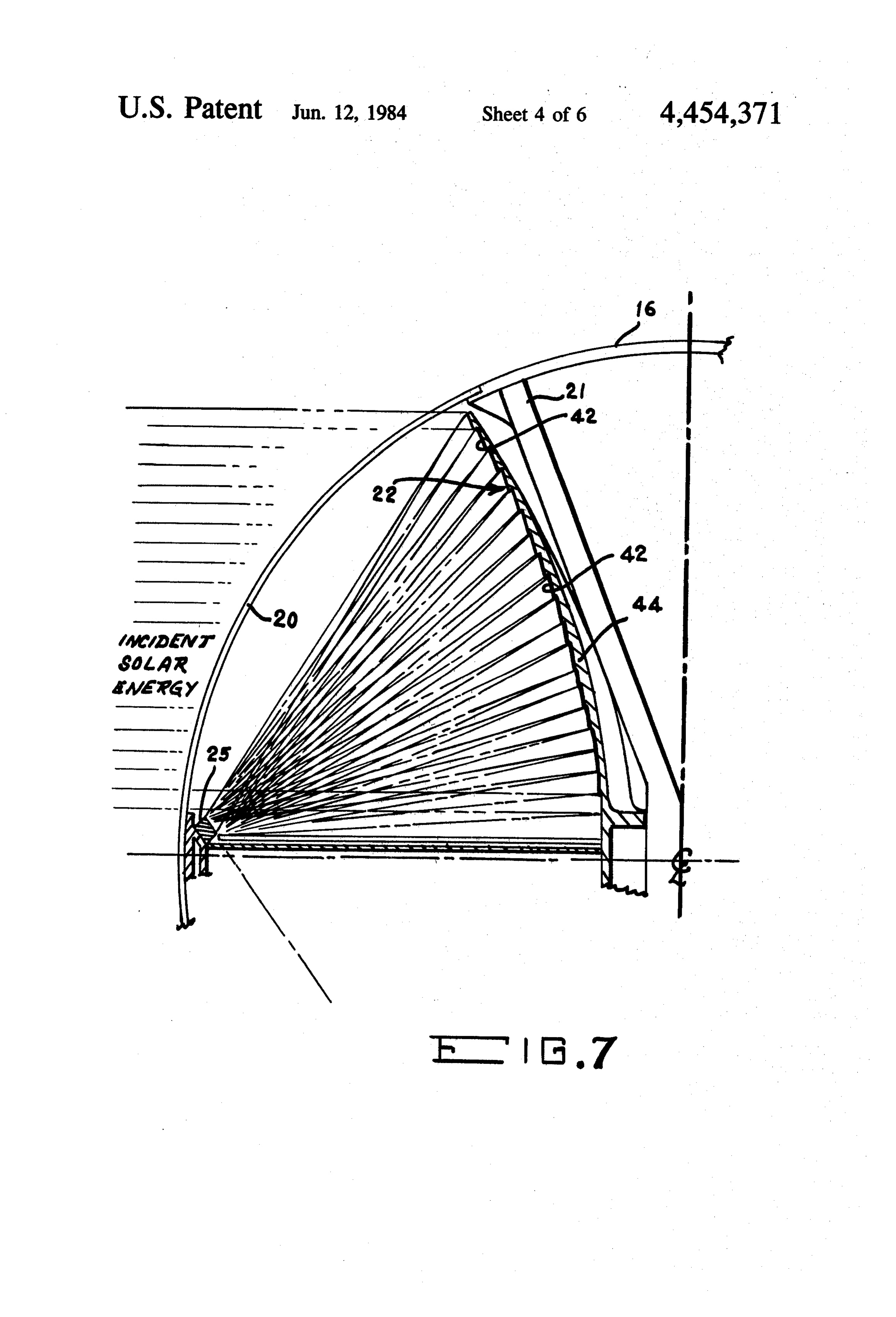
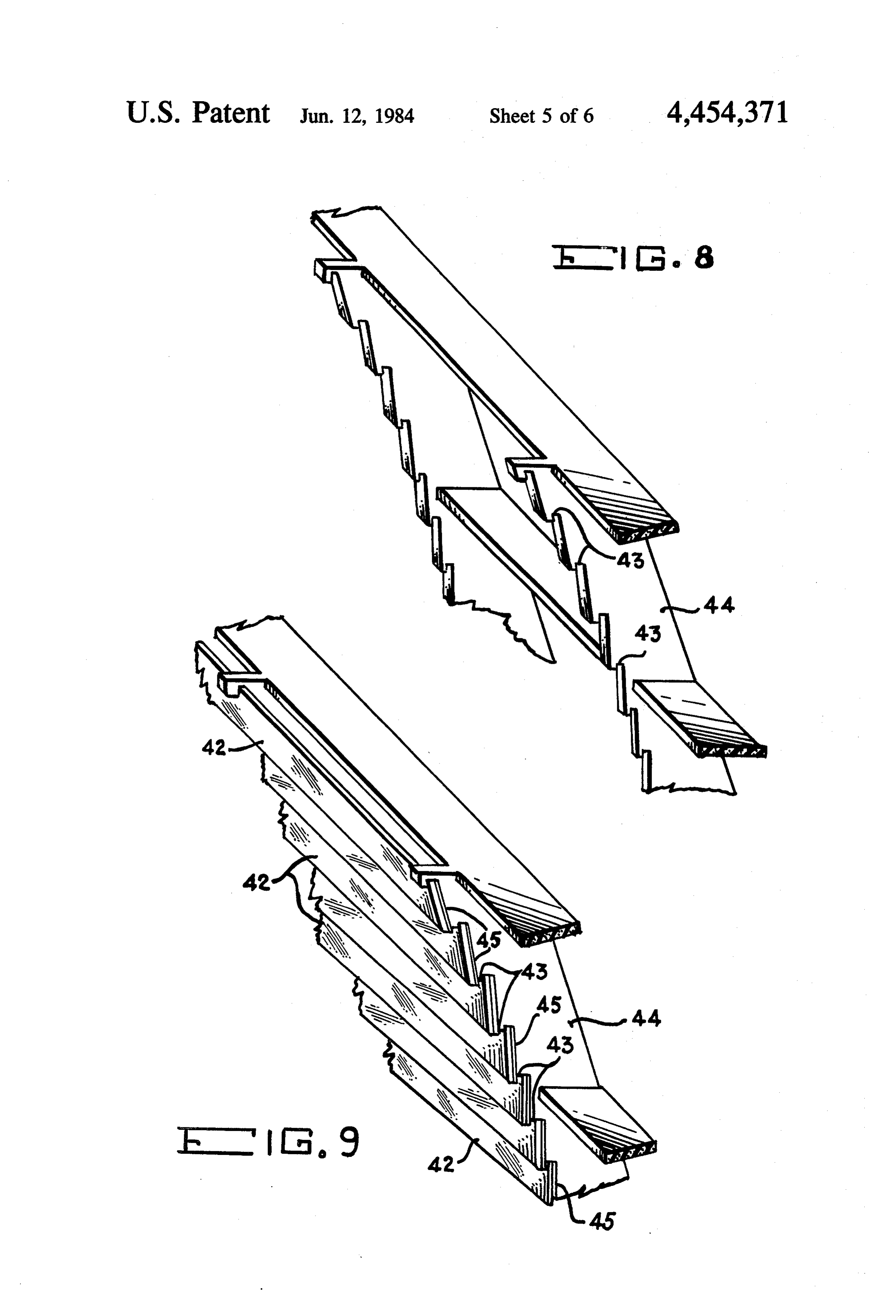
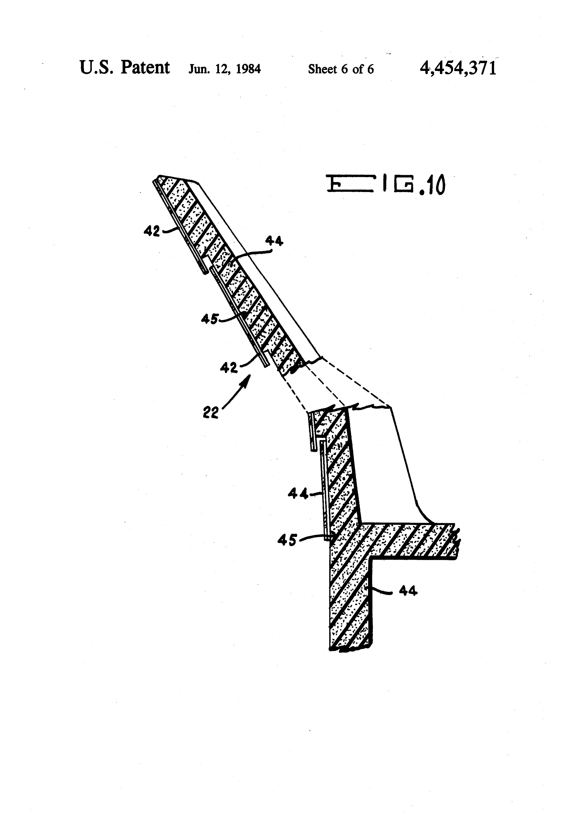
modules in order to produce a concentrator array FIG. 6 is a cross-sectional view of the photovoltaic which forms a totally intergrated contiguous reflective cells of the improved solar cell arrays of the improved surface capable of re-directing incoming solar energy to solar energy concentrator system of this invention; all the receiver cells at a nearly uniform level of illumi FIG. 7 is a partial, cross-sectional view of the im nation. The flux distribution is uniform across the image proved solar concentrator system of this invention illus width as well as the cell strings of the receiver. trating rays which are reflected from the reflective Shading at the module interface has been modulated surface of the concentrator onto the photovotaic cells; FIG. 8 is a pictorial representation of the supporting by the bias panel design resulting in this loss being dis tributed over the length of a cell string rather than a 10 structure for the reflecting elements making up the single cell. Consequently, power loss due to shading or concentrator of the improved solar energy concentrator cell mismatch has been essentially eliminated so that system of this invention and shown in segmented fash anticipated cell efficiency and cell string performance 1on;FIG. 9 is a pictorial representation of the reflecting are maintained. The need for shunting diodes or com elements in place within the supporting structure of the plex circuitry for cutting out shaded cells will therefore 15 concentrator of the improved solar energy concentrator be substantially eliminated. system of this invention and shown in segmented fash It is therefore an object of this invention to provide ion; and an improved solar energy concentrator system which substantially increases the amount of usable energy of FIG. 10 is a partially segmented cross-sectional view the supporting structure for the concentrator of the which can be derived therefrom.
improved solar energy concentrator system of this in
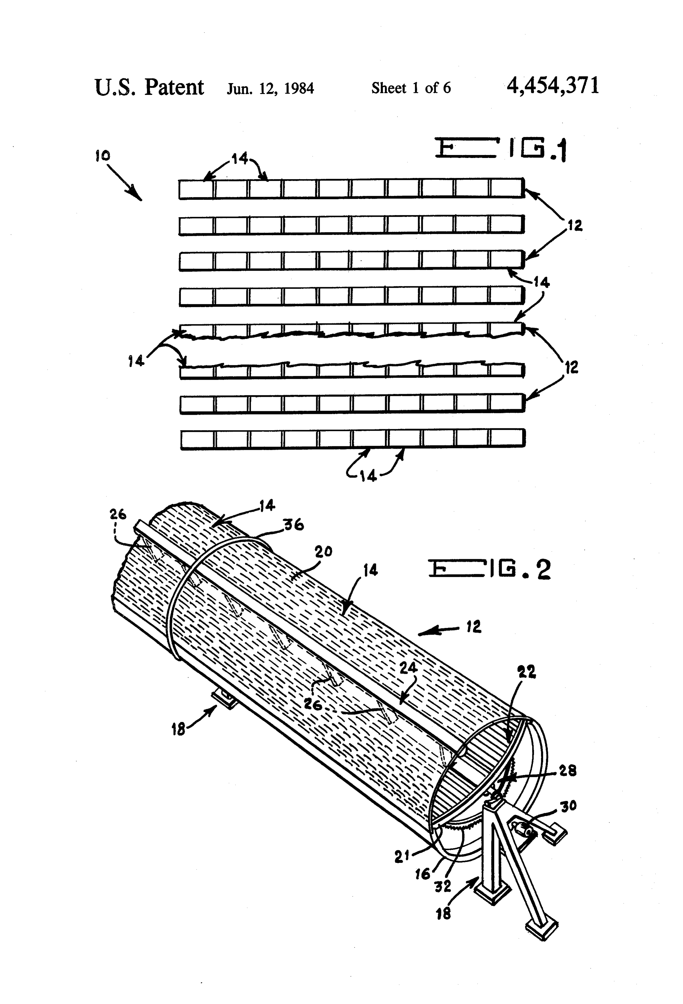
It is another object of this invention to provide an 20 vention improved solar energy concentrator system which elim with the reflecting elements in place. inates the adverse effects encountered in the past by cell DETAILED DESCRIPTION OF THE shadowing. PREFERRED EMBODIMENT It is a further object of this invention to provide an 25 Reference is now made to FIG. 1 of the drawing improved solar energy concentrator system which is which shows a plan view of the improved solar energy totally enclosed and therefore protects the components concentrator system 10 of this invention. The solar thereof from adverse environmental conditions. energy concentrator system 10 is made up of a plurality It is still another object of this invention to provide an of rows of concentrator arrays 12, each array being improved solar energy concentrator system which is 30 formed of a plurality of interconnected concentrator formed of an aerodynamically designed configuration in modules 14, forming a grid pattern situated in a location order to enable the system to withstand high wind susceptible to direct normal solar energy. It should be loads. noted that the number of rows of concentrator arrays 12 It is still a further object of this invention to provide that may be utilized in solar energy concentrator system an improved solar energy concentrator system which 35 10 of this invention may vary in accordance with the incorporates therein a very efficient structural design output needs of such a system.
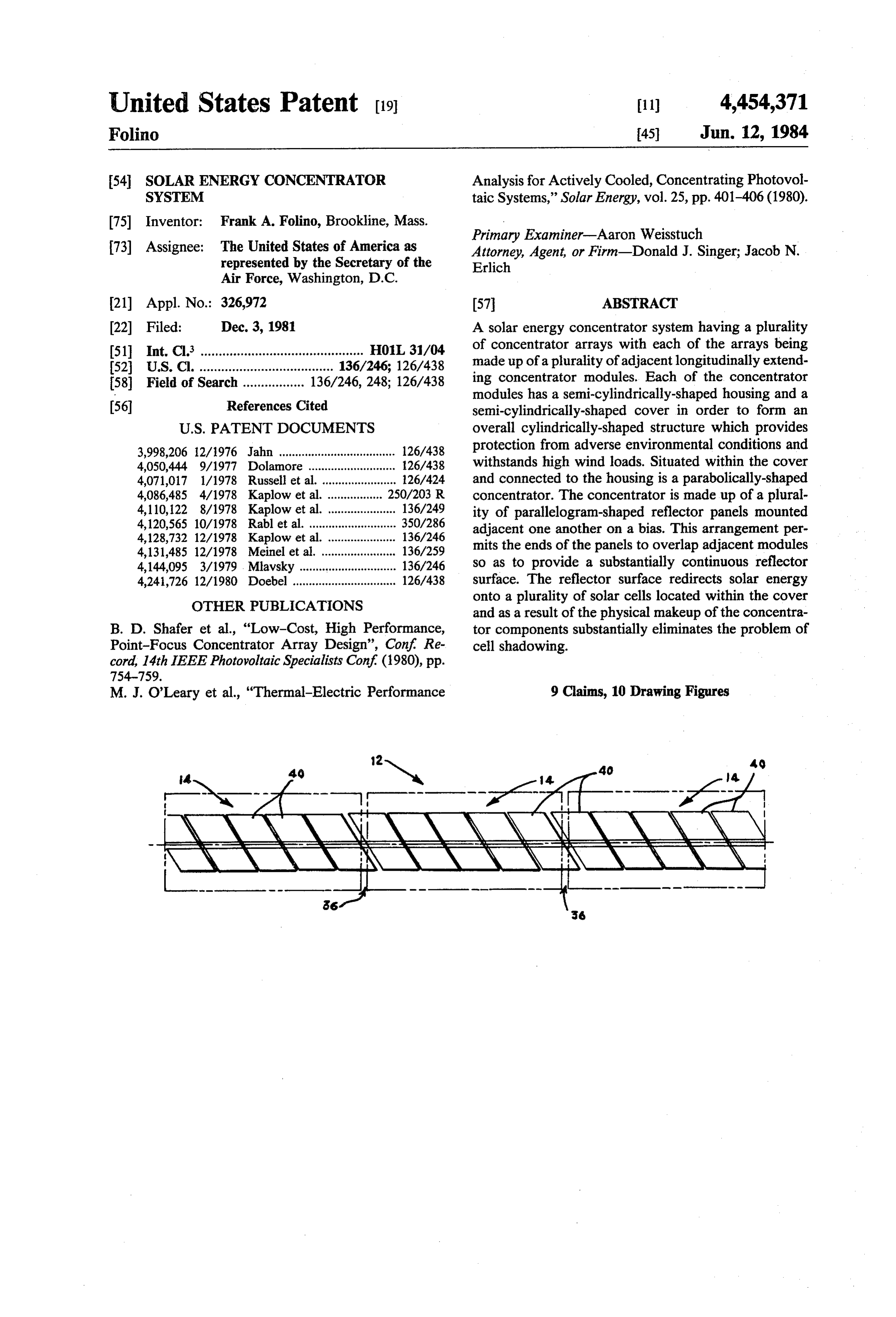
thereby offering a high stiffness-to-weight ratio result Since each concentrator array 12 is identical to an ing in significant weight savings. other, for ease of understanding of this invention, the It is still a further object of this invention to provide remaining Figures of the drawing will be directed to an improved solar concentrator system which is eco only one such concentrator array 12, and, in most in nomical to produce and which utilizes conventional, stances, to one of the concentrator modules 14, a plural currently available components that lend themselves to ity of which make up each concentrator array 12. FIG. standard mass producing manufacturing techniques. 2 clearly depicts, in segmented, pictorial fashion, such a For a better understanding of the present invention, concentrator array 12.
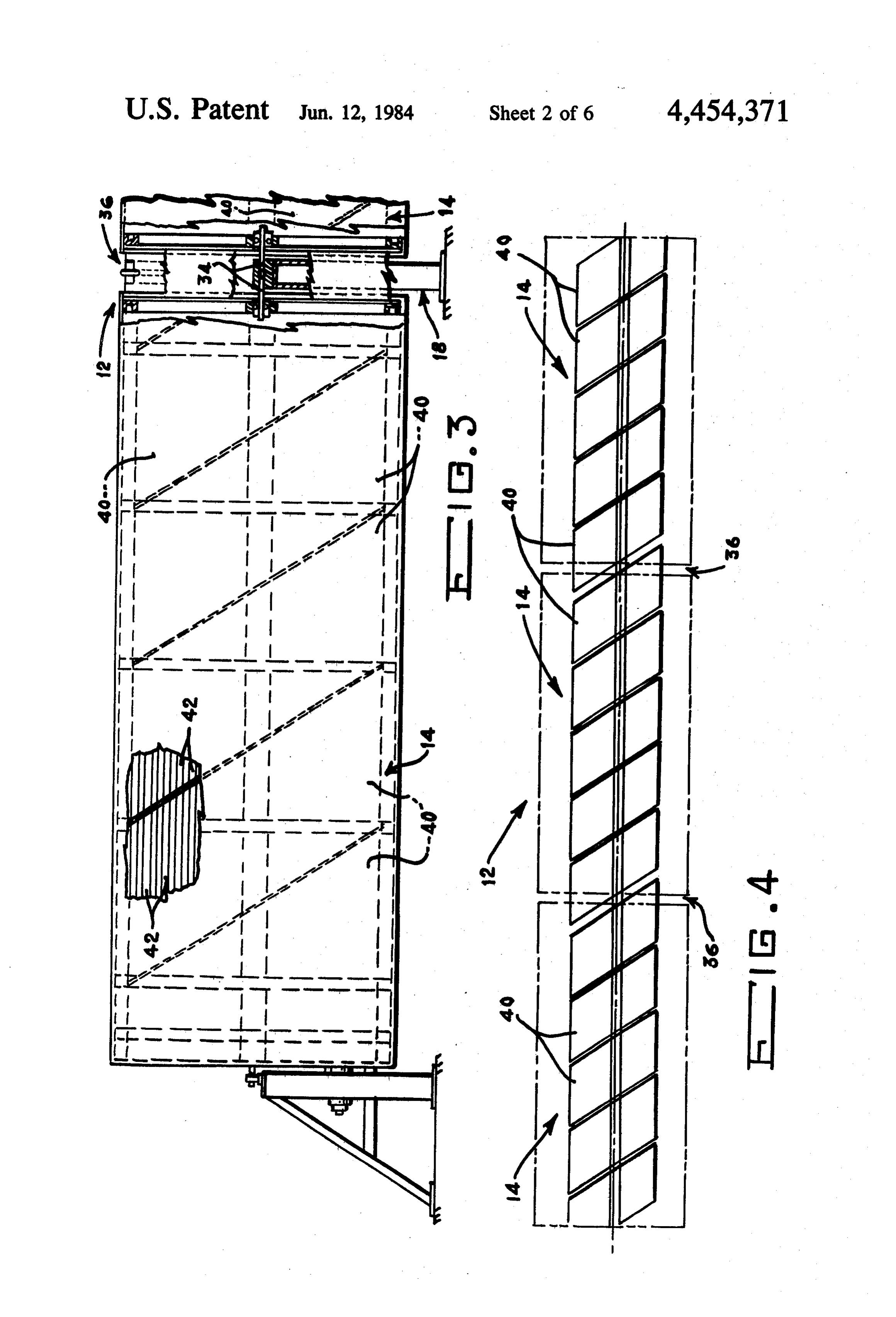
together with other and further objects thereof, refer 45 Reference is now made to FIGS. 2 through 4 which ence is made to the following description taken in con more clearly illustrate a concentrator array 12 with junction with the accompanying drawing and its scope specific emphasis being placed on the individual con will be pointed out in the appended claims. centrator modules 14. As shown in these Figures each DETAILED DESCRIPTION OF THE DRAWING 50 module 14 is made up of a longitudinal extending con centrator housing 16 rotatably supported at each end
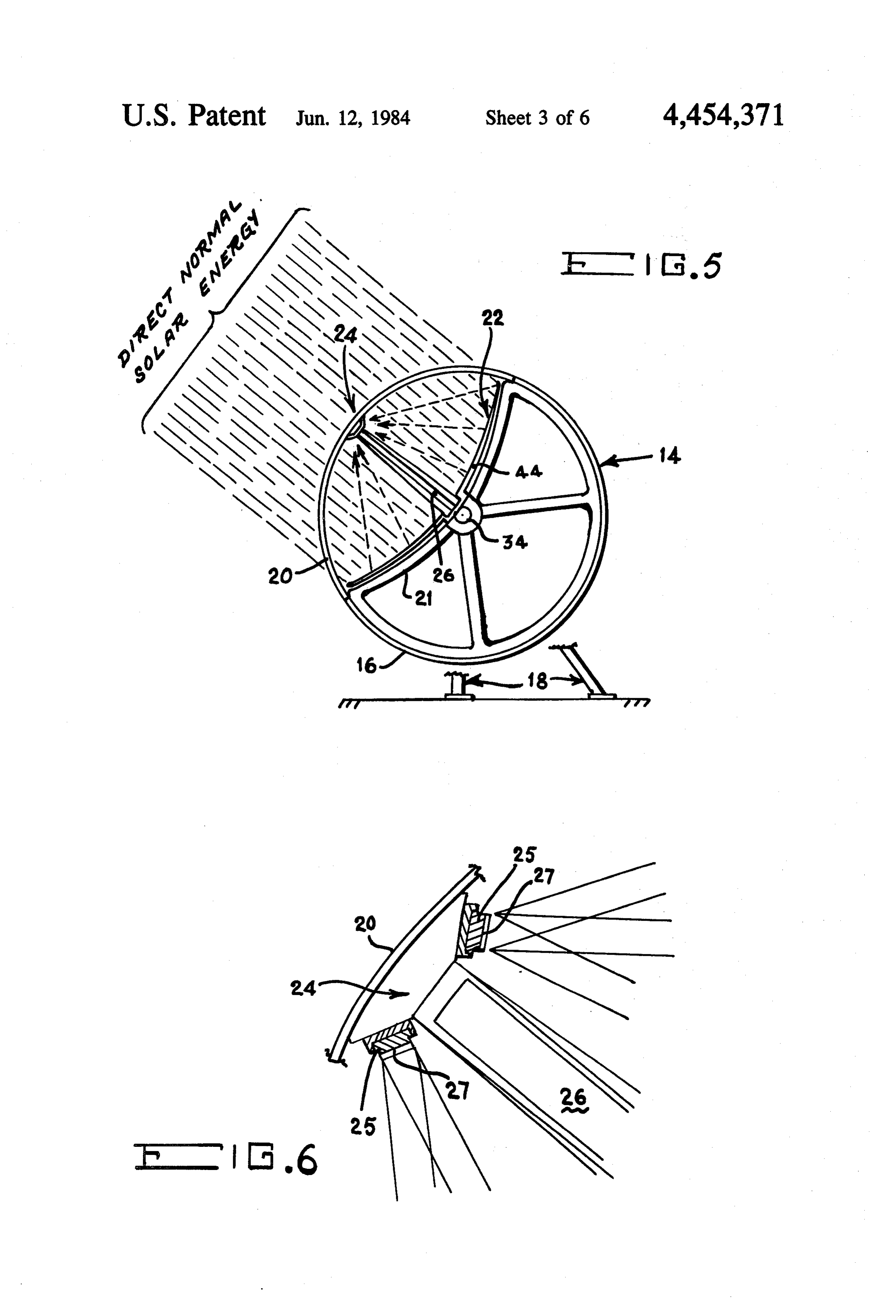
FIG. 1 is a plan view of the improved solar energy thereof by a supporting structure 18 described in concentrator system of this invention shown in array greater detail hereinbelow.
fashion and partially segmented; A transparent removable cover 20 is mounted upon FIG. 2 is a pictorial representation of the improved housing 16 and together therewith forms a preferably solar energy concentrator system of this invention 55 cylindrical, highly aerodynamic configuration. A frame shown in segmented fashion; 21 (shown in FIG. 5) located within housing 16 and FIG. 3 is a side elevational view of the improved situated within cover 20 supports a parabolically solar energy concentrator system of this invention shaped concentrator 22, the details of which will be set shown in segmented fashion with the interconnection forth hereinbelow. A longitudinal extending solar en between adjacent concentrator modules shown in cross ergy receiver 24 (shown in FIGS. 2, 5 and 6 of the section; drawing) is centrally supported upon frame 21 under FIG. 4 is a schematic side elevational view of the cover 20 by a plurality of support struts 26. Receiver 24 solar energy concentrator system of this invention illus is made up of an array 25 of solar cells 27, the specific trating, in particular, the bias arrangement of the paral makeup thereof being set forth below. lelogram-shaped reflecting panels; 65 With reference once again to FIGS. 2 and 5, cover 20 FIG. 5 is an end view of one of the concentrator is made of a material which is transparent to the wave modules of the improved solar energy concentrator length of interest, that is, the wavelength of the solar system of this invention; energy emitted from the sun. A preferred material for
Page 10
such a cover 20 would be a thin acrylic sheet which not The enclosure design of this invention will effectively only has good structural integrity over a large tempera seal out the external inclement weather so that in effect ture range but also has good anti-wetting and anti cells 27 are less costly, gain in cell performance and absorption properties. Utilizing an acrylic cover 20 access for replacement and/or jumping inoperative having a daily average transmissivity of 90% with this cells is more available.
invention would produce less than 5% discoloration Referring now to FIGS. 3 and 4 of the drawing, each over 20 years. Substantial inclement weather including concentrator 22 is made up of a plurality of identical up to 100 mile per hour winds could be sustained by the reflector panels 40. The reflector panels 40 are made of cylindrically-configured concentrator design of this a parallelogram-shaped configuration and mounted invention. In fact, continuous operation could be main O adjacent one another on a bias in order to form concen tained even with winds up to 50 miles per hour on clear trator 22. In this manner, panels 40 of each module 14 days. can overlap the space 36 between adjacent modules 14, As shown in FIGS. 2 and 3 of the drawing the plural thereby eliminating the problem of shadowing. ity of modules 14 of each concentrator array 12 are Each of the panels 40 as illustrated in FIGS. 7-10 are supported at the ends thereof by supporting structures 15 formed of a parabolically-shaped sub-frame 44 mounted 18 which allow rotational movement of the plurality of upon main frame 21 as shown in FIGS. 5 and 7 of the modules 14 to take place. Any suitable driving mecha drawing. A plurality of longitudinally extending reflec nism 28 in the form of, for example, a motor 30 and tor strips 42 are positioned in overlapping relationship suitable gearing arrangement 32 operably connected to with respect to one another in a direction transverse to end support 18 permits appropriate rotation of modules 20 the longitudinally extending direction upon sub-frame 14 to take place. The driving mechanism 28 is utilized in 44 as clearly illustrated in FIGS. 7, 9 and 10 of the conjunction with conventional control means (not drawing. The reflector strips 42 are configured so as to shown) to cause the concentrator modules 14 to auto each direct a predetermined amount solar energy to the matically track the sun in a manner well known in the photovoltaic cell arrays 25. A typical width for each art as the earth rotates. 25 reflector strip 42 (although not limited thereto) could be More specifically, modules 14 are interconnected to 7/16 inches. The offset 43 (FIGS. 8 and 9) between each other by centrally located rods 34 as illustrated in strips 42 allows for the overlapping of the individual FIG. 3, Rods 34 are maintained in rotatable position reflector strips 42 and thereby presents a reflective within the supporting structures 18. As with prior solar surface capable of reflecting 100% of the incident solar energy systems, the solar energy concentrator system 30 energy. w 10 of this invention has each concentrator array 12 Reflector strips 42 for approximately 95% reflectiv made up of a plurality of modules 14 rather than a single ity and are made of any conventional silvered material large unit, since each module 14 is generally approxi such as Corning Microsheet Glass. The reflector strips mately 20 feet in length and would be virtually impossi 42 are bonded to molded sub-frame 44 which is prefera ble to support if made as a single unit. 35 bly made of a structural foam such as polyurethane. The As a result of the mounting arrangement shown disparity of coefficients of thermal expansion between clearly in FIG. 3, a gap or space 36 is formed between the glass of reflector strips 42 and the foam sub-frame 44 adjacent modules 14. This space 36 accounts for the cell necessitates the intervention of a barrier in the form of shadowing problems which have been encountered in for example, an aluminum substrate 45 therebetween in the past and described in detail in the background of the order to ameliorate the differential expansion which invention. In order to overcome this problem the pres arises between the two materials.
ent invention has incorporated therein a uniquely de As shown in FIGS. 8 and 9 of the drawing sub-frame signed concentrator 22, the details of which will be set 44 is made of an egg crate structural configuration and forth hereinbelow. has been established both with structural integrity and As shown in FIGS. 5-7 of the drawing, concentrator 45 heat transfer considerations. This design provides a 22 is parabolically-shaped and designed so as to redirect more effective conductive path for the thermal energy incident solar energy onto the longitudinal extending absorbed by the reflecting strips 42 and the aluminum solar energy receivers 24. Each receiver 24 is in turn substrate 45. In fact, approximately 97% of the alumi made up of a pair of spaced parallel, longitudinally num substrate 45 is directly exposed to air from the cool extending conventional solar or photovoltaic cell arrays 50 side of sub-frame 44.
25. Each cell array 25 is composed of a plurality of MODE OF OPERATION individual solar cells 27 connected in series, with each array 25 being preferably 20 feet in length. Receiver 24 The improved solar energy concentrator system 10 of has an aperture plane established at preferably 60 to the this invention as illustrated in FIG. 1 of the drawing is focal axis of concentrator 22. This attitude will bound 55 made up of a plurality of concentrator arrays 12 com the acceptance angle of the irradiated energy from 0 posed of a series of ten concentrator modules 14 struc degrees to 28 degrees. turally and mechanically interconnected. The orienta Each concentrator array 12 is shown as having ten tion of arrays 12 are aligned such that concentrators 22 modules 14 which, therefore would contain a series will track the sun about a horizontal east-west axis. By string of 48 cells 27. It should, however, be realized that combining the ten modules 14 a totally integrated con the number of modules 14 in an array 12 may vary in tiguous concentrator surface is capable of irradiating accordance with the energy requirements. Cells 27 are the solar incident energy to solar receiver 24 at as preferably in the form of photovoltaic cells of nearly a uniform level of illumination as possible. Such 2.0X 1.990 inches and are capable of convering an irra an arrangement produces a maximum output. diated peak flux density of 24 suns. As a result of cover width The flux distribution is uniform across the image 20 which encapsulates concentrator 22 and receiver 24 as well as cells 27 of receiver 24. Shading at the it is possible to eliminate individual encapsulation re module interfacing has been modulated by the bias de quirements of the environmentally exposed cells 27. sign of panels 40 illustrated in FIGS. 3 and 4 of the
Page 11
drawing. Such a design results in losses being distrib (b) each of said concentrator arrays including a plu uted over the length of the cell array 25 rather than a rality of spaced adjacent longitudinally extending single cell 27. Consequently, power losses due to shad concentrator modules;
ing or cell mismatch have been essentially eliminated so (c) means interconnected between said adjacent con that maximum cell efficiency and cell performance can centrator modules for rotatably supporting said be attained. The use of blocking diodes and associated concentrator modules as a unit; complex circuitry for cutting out shaded cells are there (d) means operably connected to each end of each of fore not required. said concentrator arrays for supporting each of said The highly efficient overall cylindrical design of the concentrator arrays and for providing controlled structure of this invention, which incorporates therein 10 rotational movement thereto; cover 20, is capable of maximum operation even with a (e) each of said plurality of concentrator modules 60 mph wind loading. Such conditions would yield a having a semi-cylindrically-shaped housing and a deflection of only 0.009 inches at the midpoint of mod semi-cylindrically-shaped cover secured thereto ule 14. This deflection is immeasurably small and will thereby forming a cylindrically-shaped concentra no way cause distortions in panels 40 and reflectors 42. 15 tor module, said cover being made of a material An operative example of the solar energy concentra being transparent to the wavelength of said solar tor system 10 of this invention in order to provide a 1 energy;
Mw peak output includes 15 aligned rows of concentra (f) means connected to said housing and situated tor arrays 12 per acre for a total of 150 modules 14. within said cover for receiving said solar energy Power output per acre equals 150 x 1.214 = 182 Kw and for concentrating and directing said solar en Number of acres=1,000/182=5.50 acres ergy in a predetermined direction, said solar en Number of modules=5.5 (150)=825 ergy receiving and concentrating means including The yearly production = 2,458,500 KwH. a plurality of adjacent reflector panels, each of said Although this invention has been described with reflector panels being in the shape of a parallelo reference to a particular embodiment, it will be under 25 gram, and means connected to said reflector panels stood that this invention is also capable of further and for securing said reflector panels to said housing on other embodiments within the spirit and scope of the a bias such that the ends of said panels adjacent the appended claims. ends of said housing of each of said concentrator I claim: modules extend a predetermined distance into said 1. A solar energy concentrator system comprising: 30 space between said adjacent concentrator modules; (a) at least one row of concentrator arrays; and (b) each of said concentrator arrays including a plu (g) means mounted within said cover in optical align rality of spaced adjacent longitudinally extending ment with said predetermined direction for receiv concentrator modules; ing said concentrated solar energy and for convert (c) means interconnected between said adjacent con 35 ing said solar energy into electrical power. centrator modules for rotatably supporting said 3. A solar energy concentrator system as defined in concentrator modules as a unit; claim 1 wherein each of said reflector panels comprises (d) means operably connected to each end of each of a plurality of longitudinally extending reflector strips, said concentrator arrays for supporting each of said and said panel securing means mounting said reflector concentrator arrays and for providing controlled 40 strips in overlapping fashion adjacent one another in a rotational movement thereto; direction transverse to said longitudinal direction. (e) each of said plurality of concentrator modules 4. A solar energy concentrator system as defined in having a semi-cylindrically-shaped housing and a claim 3 wherein said panel securing means comprises a semi-cylindrically-shaped cover secured thereto frame made of a material having good insulation prop thereby forming a cylindrically-shaped concentra 45 erties and means interposed between said frame and said tor module, said cover being made of a material reflector strips for compensating for the difference in being transparent to the wavelength of said solar thermal properties between said reflector strips and said energy; frame.
(f) means connected to said housing and situated 5. A solar energy concentrator system as defined in within said cover for receiving said solar energy 50 claim 4 wherein said solar energy converting means and for concentrating and directing said solar en comprises a plurality of longitudinally extending solar ergy in a predetermined direction, said solar en cells.
ergy receiving and concentrating means including 6. A solar energy concentrator system as defined in at least one reflector panel, said reflector panel claim 5 wherein said frame is made of a molded foam being in the shape of a parallelogram, and means 55 material and said compensating means is made of an connected to said reflector panel for securing said aluminum substrate.
reflector panel to said housing such that each end 7. A solar energy concentrator system as defined in of said panel extends a predetermined distance into claim 6 wherein said concentrator is formed of a said space between said adjacent concentrator parabolically-shaped configuration.
modules; and 60 8. A solar energy concentrator system as defined in (g) means mounted within said cover in optical align claim 7 further comprising a plurality of concentrator ment with said predetermined direction for receiv OWS.
ing said concentrated solar energy and for convert 9. A solar energy concentrator system as defined in ing said solar energy into electrical power. claim 8 wherein said cover is made of a thin sheet of 2. A solar energy concentrator system comprising: 65 acrylic material. xk xk ck ck k (a) at least one row of concentrator arrays;
Provenance
- Collection
- Cited prior art
- Original PDF
- patentimages.storage.googleapis.com →
- Filed
- 1981-12-03
- Pages
- 11
- Method
- pdftotext (the PDF's own text layer) + pdftoppm 300dpi page scans
- Source
- Google Patents bibliographic record
- Granted
- 1984-06-12
- Inventors
- Frank A. Folino; United States Department of the Air Force
- Transcribed from
- patentimages.storage.googleapis.com →