patent · US3492461
Apparatus for the protection of structures exposed to heat storage compositions
27 January 1970
Page 1
Drawing sheet — no readable text.
Page 2
Drawing sheet — no readable text.
Page 3
Drawing sheet — no readable text.
Page 4
Drawing sheet — no readable text.
Page 5
Jan. 27, 1970 W. T. LAWRENCE 3,492,461
APPARATUS FOR THE PROTECTION OF STRUCTURES EXPOSED
Filed Dec. 28, 1967 TO HEAT STORAGE COMPOSITIONS 5 Sheets-Sheet 5
aYaNNNYaNY 42 YaYa YaYaNYaYaNYaYaNYaNYSYaNYS
WILLIS THOMPSON LAWRENCE
A77 Oaway
Page 6
United States Patent Office 3,492,461 Patented Jan. 27, 1970
sitating protection of the heating element other than to 3,492,461 make the distance between pockets in the refractory
APPARATUS FOR THE PROTECTION OF material sufficiently large to resist strains during assembly, STRUCTURES EXPOSED TO HEAT STORAGE disassembly and during operation.
COMPOSITIONS
Willis Thompson Lawrence, Winchester, Mass, assignor, Plumb, in U.S. 1,790,555, issued Jan. 27, 1931, dis by mesme assignments, to Hooker Chemical Corpora closes the use of a solid heat storage material through tion, Niagara Falls, N.Y., a corporation of New York which a heat exchange coil horizontally disposed is par Filed Dec. 28, 1967, Ser. No. 694,323 tially embedded. No mention of any problem of coil Int. CI. H05b 1/00, 3/02, F24h 7/00 distortion is made by the patentee, even though the coil U.S. C. 219.325 12 Claims O E. g protected. The coil is in fact a reverse spring wound
ABSTRACT OF THE DISCLOSURE It is an object of this invention to prevent the distortion of structures within the alkali metal hydroxide com
The useful life of a heat storage apparatus which position used for heat storage media in a heat storage employs a substantially anhydrous alkali metal hydroxide 5 vessel.
heat storage composition is extended by protecting and It is a further object of this invention to avoid the confining all internal structures to the approximate region stresses placed upon the heating elements and conduit of their original position by shielding from adverse forces for heat transfer material which are exposed to alkali with rigid structural members, bundling several structures metal hydroxide heat storage material in a heat storage to produce a combined structure of increased strength or 20 vessel.
providing a molten sheath of heat storage material around It is a further object of this invention to provide shield the internal structure. The heating of the heat Storage ing members for the internal structures of a heat storage material is by electrical resistance heaters. apparatus.
In accordance with this invention, it has been dis 25 covered that the creep of internal structures within an
Brief summary of the invention alkali metal hydroxide heat storage composition, whether In the operation of heat storage equipment which oper by theexposure from to high temperature or the stress caused expansion and contraction of the heat storage ates on the heat of fusion concept characteristic of alkali material during solidification and melting may be avoided metal hydroxide compositions, the heat storage medium 30 by shielding the internal structures. The concept of pro passes from a solid state to the liquid state in a com tecting internal structures embraces broadly containment plete operating cycle. Alkali metal hydroxide composi of the structure to prevent lateral, horizontal or any tions, when used as heat storage material, cause severe oblique movement of the structure from the original stress in the internal structures of a heat storage vessel configuration and disposition of the structure within the because of their extremely high adhesive strength to metals heat storage tank. The internal structures need not be upon solidification. However, alkali metal hydroxide com 35 attached to rigid members, but must be contained within positions remain very desirable heat storage media a relatively small distance from their original position. because of their high heat capacity. Hence, the develop Therefore, the protection of the internal structures of ment of apparatus capable of housing alkali metal hydrox ide compositions for practical periods of time while re 40 heat storage tanks may embrace containment, direct shielding from adverse forces in the form of rigid mem maining functionally operational is essential to the utiliza bers which provide a bearing surface at a point for direct tion of the desired heat storage materials. attachment, or avoidance of the direct contact of solid Due to the expansion and contraction of the heat heat storage medium with the internal structure as by storage medium and because of the adhesion of the alkali providing through heating means, a sheath of molten metal hydroxide composition to the internal structures storage material around all surfaces of the internal struc within the heat storage tank, the structures may become ture which contacts the heat storage material. distorted and misshapen to the extent that they no longer function optimally. To prevent this distortion, all com elements in the heatunheated
For example, the storage lengths of several heating medium of a heat storage ponents of the apparatus which contact the heat storage tank may be protected by tying them together medium must be shielded from the forces of expansion 50 extra rigidity or by attaching them to a rigidto member provide and contraction attending the solidification and lique within the heat storage medium or by confining them faction of an alkali meal hydroxide composition.
Alkali metal hydroxide compositions which contain a between rigid members within the heat storage medium, major proportion of an alkali metal hydroxide are the or by coupling them in such manner that no unheated region of the alkali metal hydroxide composition contacts preferred heat storage materials. Specifically, the alkali the heater.
metal hydroxide composition may be one containing a Of course, if the heating elements are so designed that major amount of sodium hydroxide, a minor amount of they have no unheated sections below the surface of the sodium nitrate and a minor amount of a corrosion heat storage material, no force will be exerted upon them inhibitor.
The problem of distortion of structures in contact with because they will always be surrounded with a sheath of molten material. This same result may be effected alkali metal hydroxide compositions within a heat storage 60 by container appears to be a unique problem attending the mentcombining to another heater with the first heating ele provide heat near any section of the first heater use of alkali metal hydroxide compositions. Keene, in which is not heated thereby maintaining a sheath of U.S. 1,555,292, issued Sept. 29, 1925, discloses an electric molten material around both heating elements. In the furnace containing as the heating element, a resistor wire absence of bundled heater elements or heating elements wound in the form of a flat helix, the end of each turn which have no unheated sections exposed to the alkali in the heating element is supported by a "spaced pocket' metal hydroxide composition, it is necessary to contain or in a refractory member fitted to a metal frame. "Any shield the heater element from excessive forces resulting movement of the end portions of each turn of the resistor from heating member proper is prevented in both a lateral and longi 70 like manner a and cooling of the storage material. In distinct heater may be disposed along the tudinal direction relative to the heating unit . . . .” This path of the heat transfer conduit to maintain a molten reference does not disclose the nature of the material to sheath of material in all areas of contact with the storage be heated nor does it discuss any specific problem neces material.
Page 7
In one preferred embodiment of this invention, a heater coil 14 along the horizontal axis. The cross members 26 is run along the length of the heat transfer conduit. arrest downward travel of the conduit 14. Thus, the cross In operation, the heater maintains a sheath of molten members 26 are disposed to provide a resting platform material around the heat transfer conduit thereby pro or shelf upon which conduit 14 will bear when an adhe tecting it from the forces of expansion and contraction. sive force is exerted upon the conduit during expansion In another preferred embodiment of this invention, or contraction of heat storage composition 12. Cross applicable to the protection of the heat transfer conduit members 26 may also be provided with extension mem when it is provided with a flat spiral in the heat storage bers which protrude upwardly in the region defined by material, immediately below the flat spiral of the conduit the heat transfer conduit where 14 extends beyond frame a heater is mounted which is bent to provide a high heat 10 24. The vertical frame 24 as depicted in FIGS. 4 and 5 density in the region of the flat spiral. may be hung from the top 11 of the heat storage vessel 10 In both of these modifications of the invention, an shown in FIGS. 1 and 2, or disposed within heat storage additional advantage is provided. That is, heat from the composition 12 in any manner.
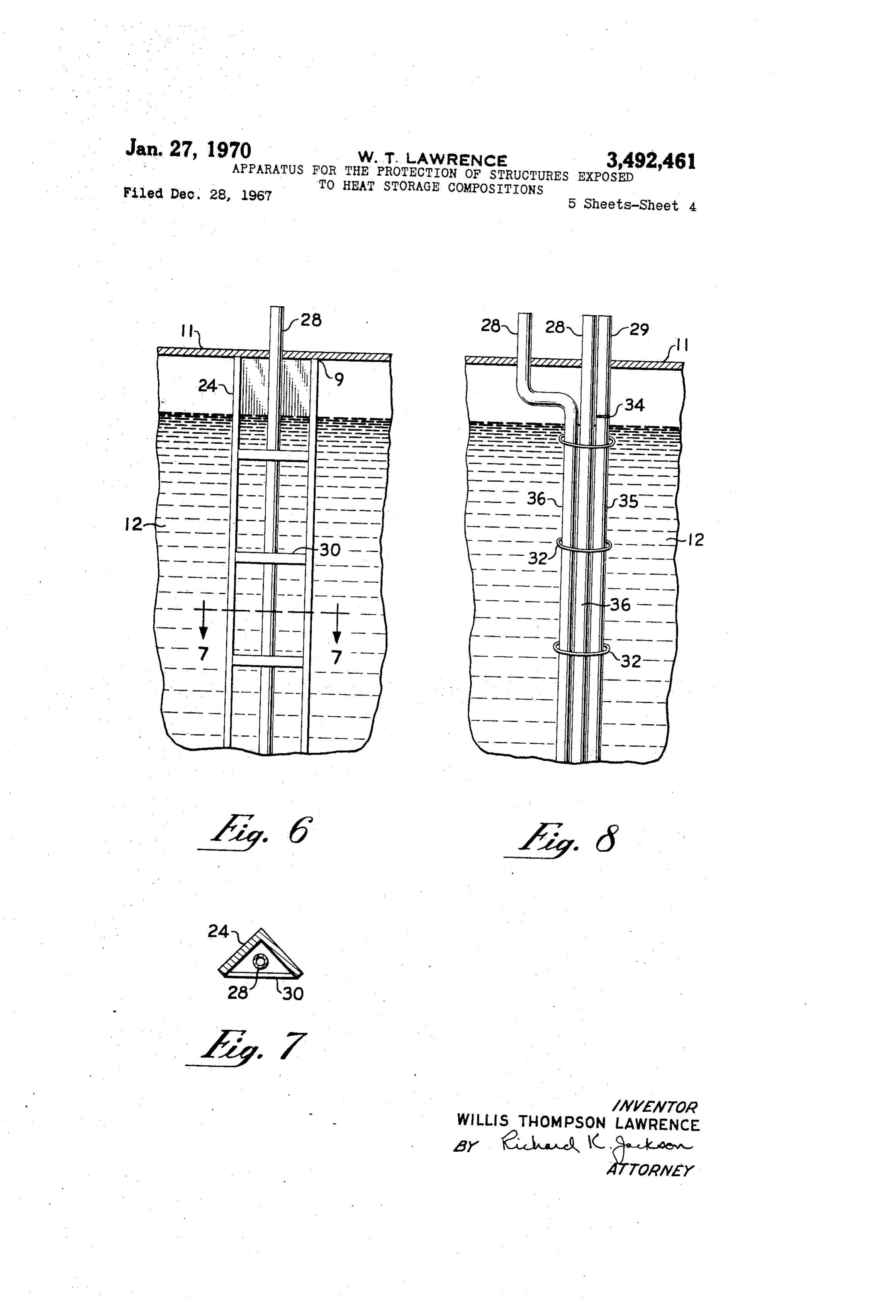
heat storage material may be withdrawn at a rate close FIGS. 6 and 7 illustrate an apparatus which will pro to the input rate from the electric heater during periods 5 tect any unheated portion of a heating element 28 which when the heat storage material is discharged. This rapid is exposed to the forces of expansion and contraction of delivery of heat is important during periods when the heat heat storage material 12. A piece of angular metal 24, stored in the alkali metal hydroxide composition has attached to the top 11 of the heat storage vessel at 9, reached a level too low for practical heating efficiency. with straps of metal 30 attached across its open face will 20 contain heater element 28 and prevent distortion and
Detailed description of the invention migration from the optimum heat situs. This concept is, The invention may best be understood by consideration of course, applicable to the heating element depicted in FIGS. 2 and 3 which may be of the type which provide of the various embodiments presented in the accom heat only in the region of the flattened spiral of heat panying drawings. 25 transfer conduit. In another application, the heater leg 28
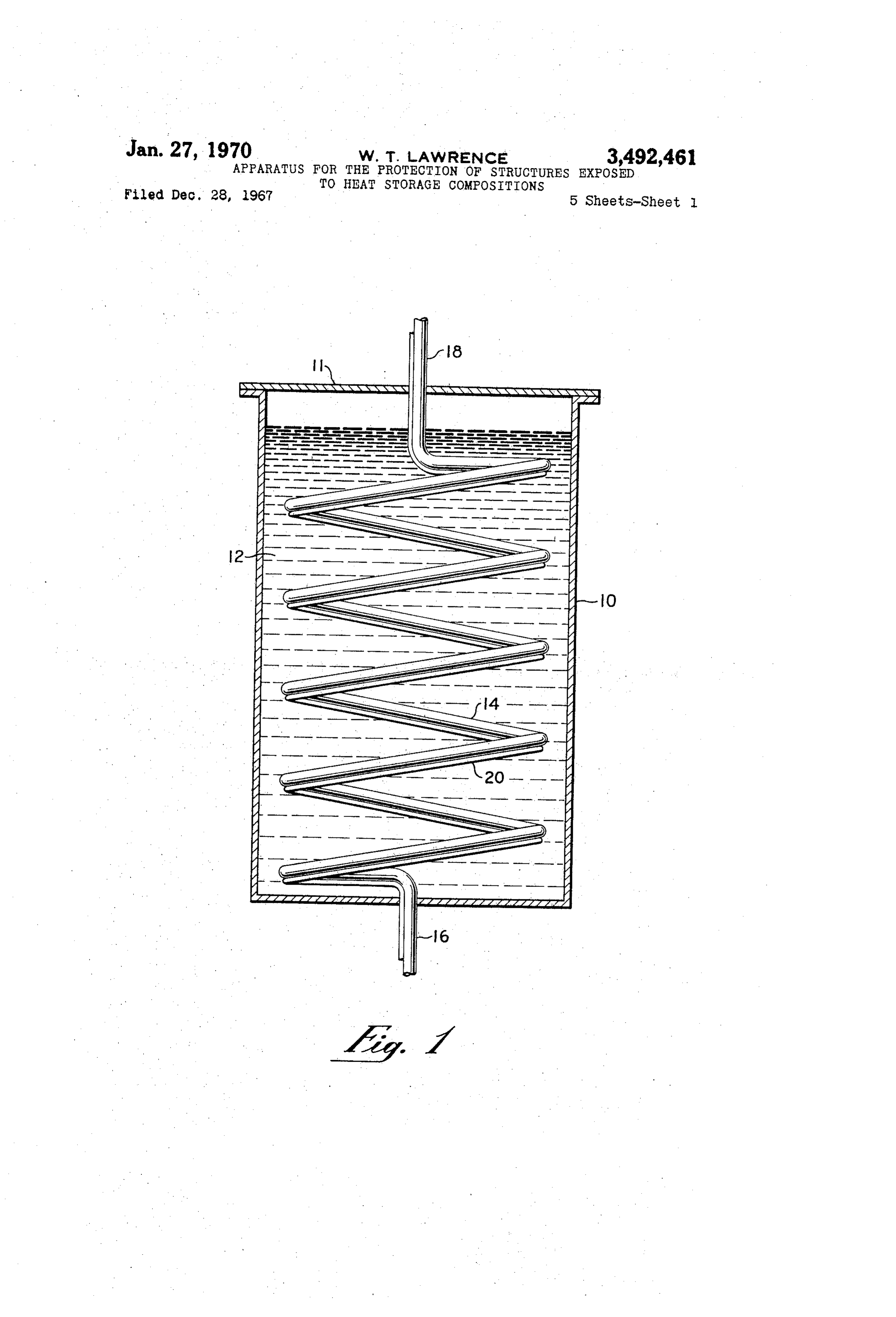
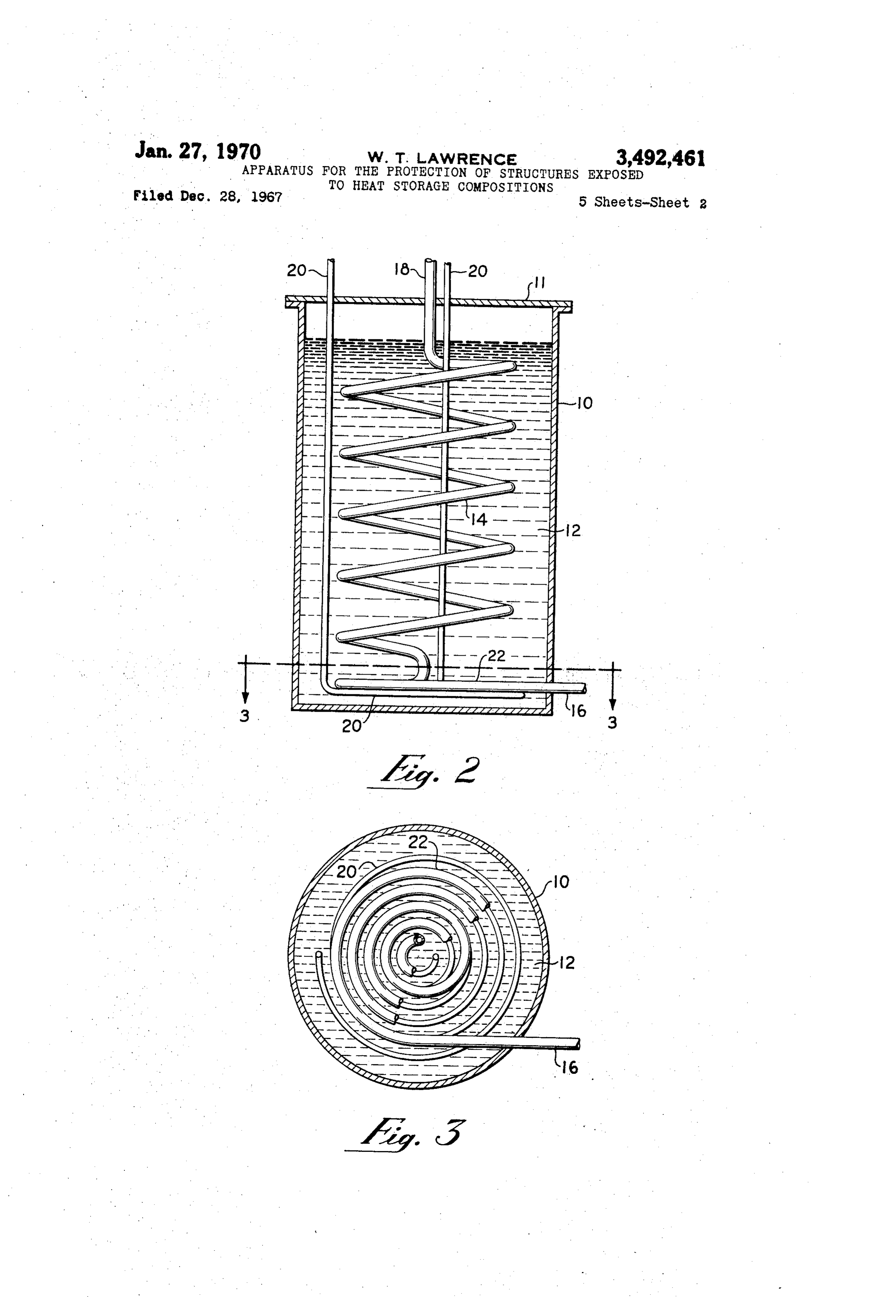
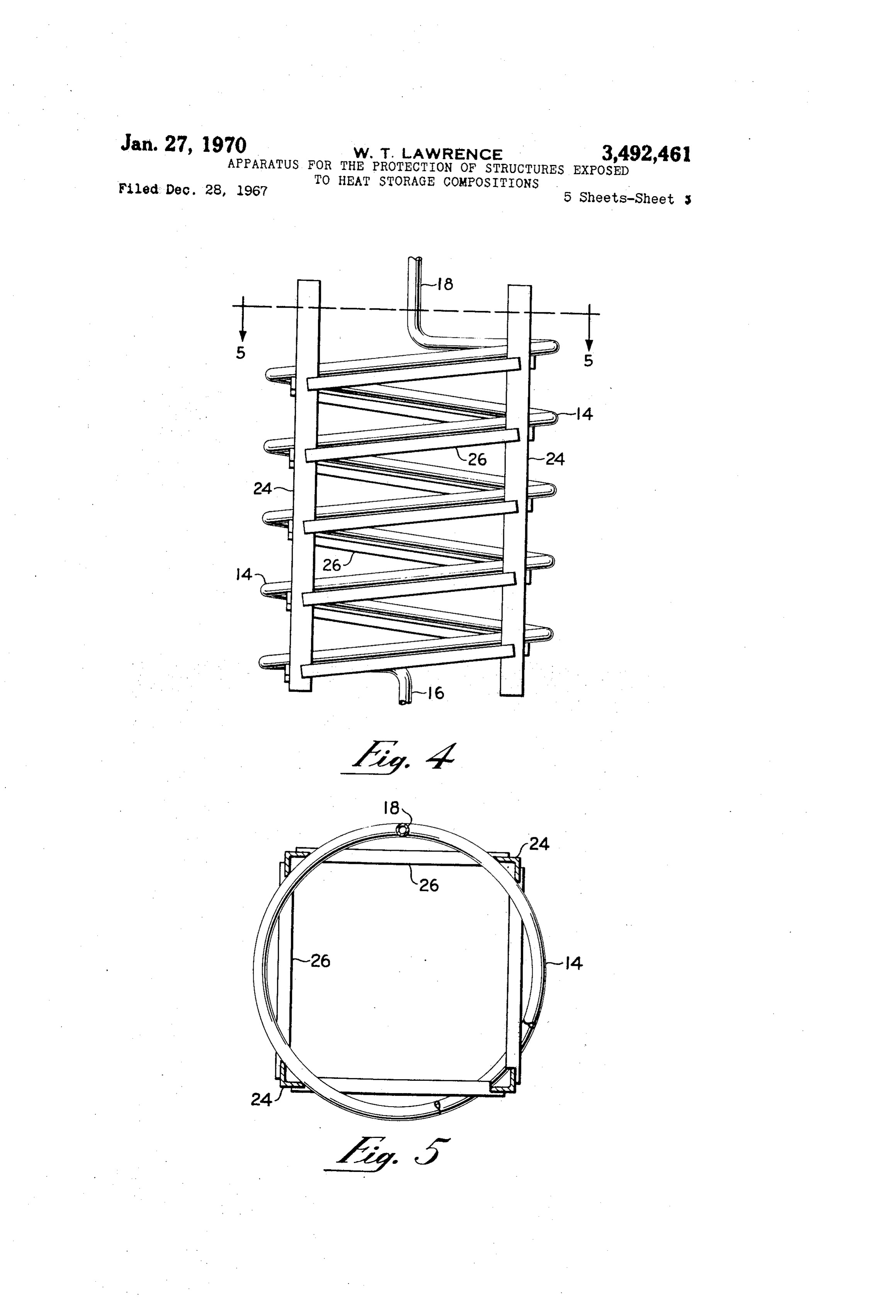
FIG. 1 represents a sectional view of the configuration of a heat transfer conduit and a protective heater therefor, vertical frame 24 asindepicted could be inserted an angle iron which provides the in FIGURE 4. The unheated housed within a heat storage vessel. portion of the heater leg 28 would thereby be contained FIG. 2 represents another protective disposition of a by the vertical frame 24 and the heat transfer conduit 14. heat transfer conduit as a flat spiral with a heater directly
FIGURE 8 illustrates another protective device for the below. unheated portion 36 of a heater 28 by bundling heater FIG. 3 represents a top view of FIG. 2 taken along element 28 with a heater element 29 so as to provide a plane 3-3. heated portion 35 of heater 29 adjacent to the unheated FIG. 4 represents a sectional view of a heat transfer portion 36 of heater 28. The head portion of 29 extends
from 34 down. Thusly, all parts of heaters exposed to
FIG. 5 represents a top view of FIG. 4 taken along the heat storage material 12 will be provided with a plane 5-5. molten sheath of material to prevent distortion during FIG. 6 represents a sectional view of a heating element expansion and contraction. These bundled heaters may be and protective assembly therefor. held within operable proximity to the adjacent heater FIG. 7 represents a top view of FIG. 6 taken along 40 with a binding 32 in the form of wire or other means. plane 7-7. The heated and unheated portions 35 and 36, respectively, FIG. 8 represents a diagrammatic representation of may be legs of the same heater. bundled heater elements,
FIG. 9 represents a sectional view of a heat storage In the same manner as is depicted in FIGURE.8, several vessel in which a heat transfer conduit presents alternate 45 unheated electrical resistance heater legs may be bundled together to provide a composite structure with more turnings of consistently varied diameter contained by frame members hung from the top of the vessel and in strength than that of the sum of the individual legs. The which the heating element is contained between the heat bundled heater legs may be held together with a binding transfer conduit and the frame member. 32 in the form of wire or other means whether or not the
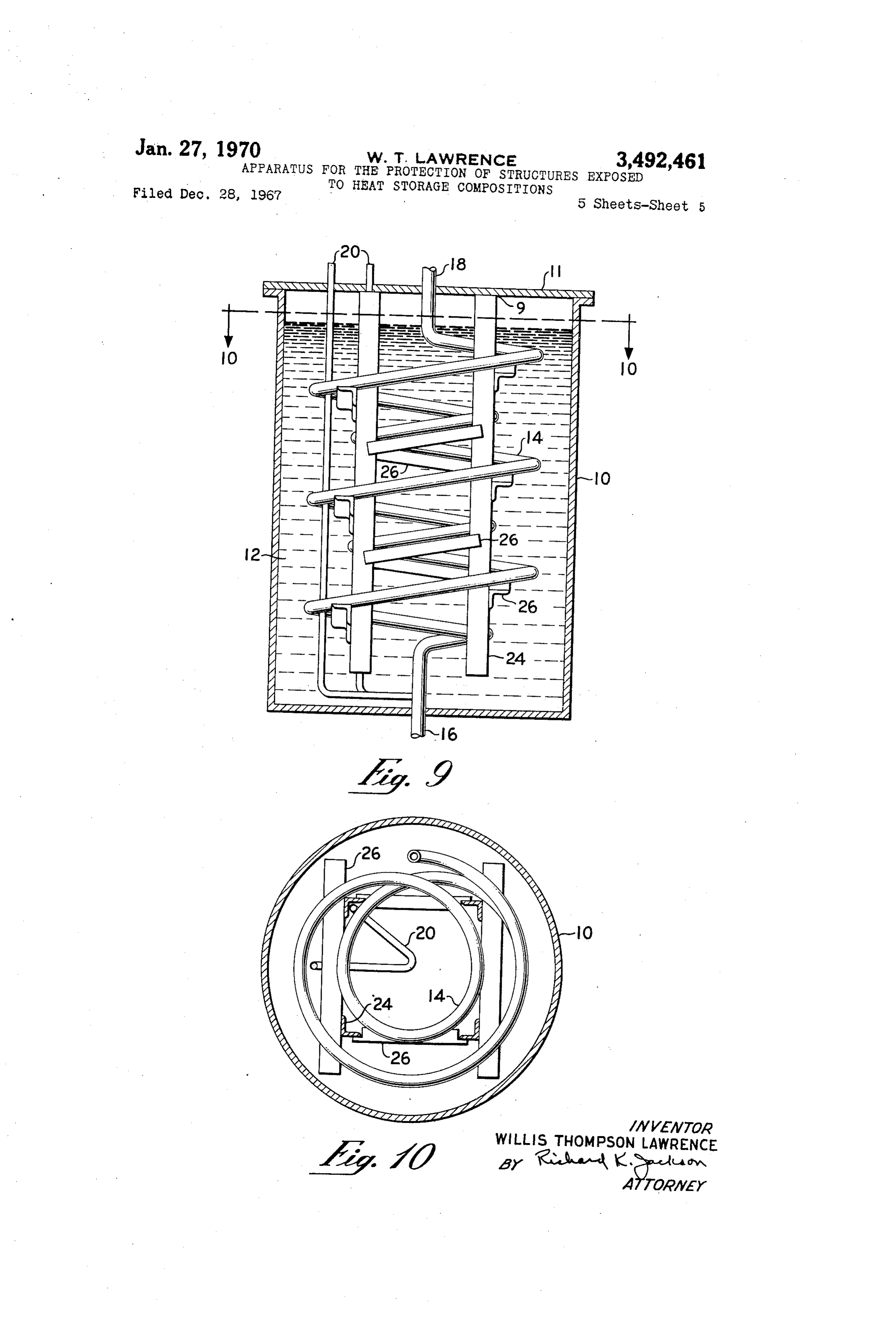
FIG. 10 represents a top view of FIG. 9 taken along 50 as heated section of heater element 29 as shown in FIGURE 8 plane 10-10. portion 35 is heated. In the first instance, heater Specifically, with reference to FIG. 1, heat transfer fluid element 28 is protected from distortion by a molten sheath of heat storage material 12 while in the latter case a enters the heat storage vessel 10 housing a heat storage composition 12 via conduit 14 near the bottom of the mechanical structure support is provided by the hundled vessel at inlet 16. The heat transfer fluid passes through heater legs.
conduit 14 to outlet 18. Immersion heater 20 is placed FIGURES 9 and 10 illustrate a heat storage vessel 10 along heat transfer conduit 14 to provide heat and a partially filled with an alkali metal hydroxide heat storage molten sheath around heat transfer conduit 14 wherever composition 12, in which heat transfer conduit 14 extends contact with heat storage composition 12 is made, thereby from an inlet 16 to an outlet 18 via alternate turnings preventing distortion of the configuration of heat transfer 60 of consistently varied diameter. Heat transfer conduit 14 conduit 14. is contained by vertically placed frame members 24 to In FIGS. 2 and 3, another variation of heat transfer which cross members 26 are attached at an angle from conduit protection is illustrated. Immersion heater 20 is the horizontal corresponding to the descending angle of placed directly below a broad flattened spiral 22 of heat the heat transfer conduit 14. The vertical frame members transfer conduit 14 within heat storage material 12 there 65 24 are attached to the top 11 of heat storage vessel 10 by providing a molten sheath of heat storage material 12 by any suitable means such as welding or bolting to around the flattened spiral 22 to prevent distortion of 22 provide a support means hung from the top of the heat and provide for rapid heat production during any period storage apparatus for easy removal from the vessel 10. when the heat stored in heat storage material 12 is below A heating element 20 is disposed within angle via frame the level desired. 70 member 24 in such manner as to restrict its position FIGS. 4 and 5 illustate a protective device comprising between the vertical frame member and the heat transfer an upright angle iron frame 24 upon which cross members conduit 14. Heater element 20 is provided with any con 26 are placed which provide an angle from the horizontal figuration in the lower region of the heat storage material equal to the descending rate of the heat transfer coil 14. 12 as may be best seen from FIGURE 10 as a triangular The vertically placed frame 24 prevents distortion of the configuration. Heater element 20 extends from the lower
Page 8
region of the heat storage material 12 upwardly between between the descending helical conduit and the vertically the frame cross members 26 and the outer loops of the placed frame members.
heat transfer conduit 14 in such manner as to provide 9. The apparatus of claim 1 in which said heating containment on a horizontal or oblique plane. means comprise electrical resistance heaters which pro Having disclosed the invention, it is obvious to those vide heat to said heat storage composition through a of average skill in the art that various modifications of portion of their exposed surface, and said protective my invention may be made which do not depart from the means protect unheated portions of said heater. spirit and true scope of this contribution. 10. The apparatus of claim 9 in which said electrical What is claimed is: resistance heaters extend through a channel which is an 1. A heat storage apparatus comprising a vessel con angular metallic member with metallic straps attached taining an alkali metal hydroxide heat storage composi 10 across the open face.
tion, conduit means for heat transfer media and heating 11. The apparatus of claim 9 in which said protective means, said conduit means and heating means disposed means for the electrical resistance heaters is provided by in said vessel being protected from movement by means bundled heaters in such manner that heat is provided by which limit vertical and horizontal movement of said con 5 a heater in the region where heat is not provided by duit means and heating means during solidification and another heater so that the unheated portion of a heater melting of said heat storage composition. is protected by a molten sheath of heat storage material 2. The apparatus of claim 1 in which said conduit melted by a bundled heater.
means are provided with heating means which trace the 12. The apparatus of claim 9 in which said protective route of said conduit through said vessel, said heating 20 means for the electrical resistance heaters is provided by means being adapted to provide sufficient heat to melt bundled heaters in such manner that several unheated a sheath of heat storage material around said conduit. legs are bound together to provide a composite structure 3. The apparatus of claim 2 in which said heating with more strength than that of the sum of the individual means is attached to said conduit. legs.
4. The apparatus of claim 2 in which said heating 25 References Cited means is bound to said conduit.
5. The apparatus of claim 1 in which said conduit UNITED STATES PATENTS forms a flat spiral and heating means are placed in such 2,687,626 8/1954 Bartlowe --------- 165-164 X proximity to said flat spiral that said conduit is protected 2,911,513 11/1959 MacCracker ------- 122-32 X by a sheath of liquid heat storage material. 30 3,062,510 1 1/1962 Percival ---------- 165-104 X 6. The apparatus of claim 1 in which said conduit 3,163,209 12/1964 Shinn ------------ 165-163 X is provided with alternate turnings of consistently varied 3,356,834 12/1967 Mekjean --------- 126-400 X diameter contained by vertically placed frame members FOREIGN PATENTS to which cross members are attached at an angle from the horizontal corresponding to the descending angle of 35 157,156 10/1939 Austria. the helically displaced conduit, said frame members and ROBERT A. O'LEARY, Primary Examiner cross members being so located as to provide substantial restriction from movement by said conduit. A. W. DAVIS, Assistant Examiner 7. The apparatus of claim 6 in which the frame mem 40 bers are hung from the top of the heat storage apparatus. U.S. Cl. X.R. 8. The apparatus of claim 6 in which said heating 126-400; 165-104, 134; 219-302, 365, 378, 530, 540 means are contained at least a portion of their length
Provenance
- Collection
- Cited prior art
- Original PDF
- patentimages.storage.googleapis.com →
- Filed
- 1967-12-28
- Pages
- 8
- Method
- pdftotext (the PDF's own text layer) + pdftoppm 300dpi page scans
- Source
- Google Patents bibliographic record
- Granted
- 1970-01-27
- Inventors
- Willis Thompson Lawrence; Hooker Chemical Corp
- Transcribed from
- patentimages.storage.googleapis.com →