patent · US3989927
Electric heater utilizing a pourable heat storage bulk
2 November 1976
Page 1 — bibliographic record
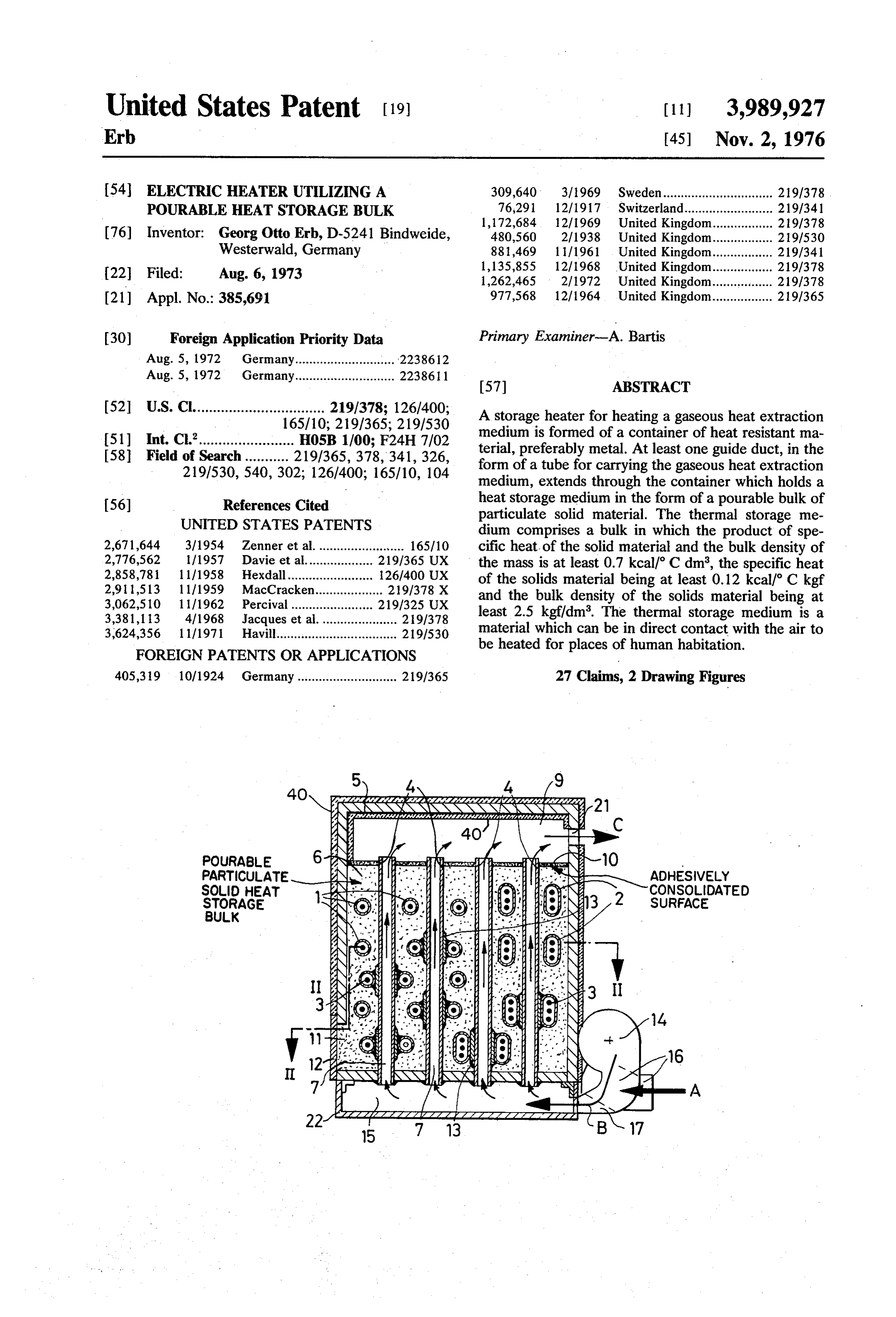
United States Patent (19) (11) 3,989,927 Erb. (45) Nov. 2, 1976 54 ELECTRIC HEATER UTILIZING A 309,640 3/1969 Sweden............................... 219/378 POURABLE HEAT STORAGE BULK 1.33: 236 a F avy
ERO 33
(76) Inventor: Georg Otto Erb, D-5241 Bindweide, 480,560 2/1938 United Kingdom................. 219/530 Westerwald, Germany 881,469 11/1961 United Kingdom................. 219/341 1. 1,135,855 12/1968 United Kingdom................. 219/378 (22 Filed: Aug. 6, 1973 1,262,465 2/1972 United Kingdom................. 219,1378 (21) Appl. No.: 385,691 977,568 12/1964 United Kingdom................. 2 191365
(30) Foreign Application Priority Data Primary Examiner-A. Bartis Aug. 5, 1972 Germany............................ 2238612
Aug. 5, 1972 Germany............................ 223861 ug ermany (57) ABSTRACT
52 U.S. Cl.......................l 657 s; 3: A storage heater for heating a gaseous heat extraction 51) Int. Cl. hose 1 f60, F24H 7702 medium is formed of a container of heat resistant ma 58 Field of search - - - - - - - - - 219/365 378 341, 326 terial, preferably metal. At least one guide duct, in the 219/530 540,302. 126,400; 165/10 104 form of a tube for carrying the gaseous heat extraction y 2 ov, y medium, extends through the container which holds a heat storage medium in the form of a pourable bulk of 56) References Cited particulate solid material. The thermal storage me UNITED STATES PATENTS dium comprises a bulk in which the product of spe 2,671,644 3/1954 Zenner et al......................... 165/10 cific heat of the solid material and the bulk density of 2,776,562 1 / 1957 Davie et al................... 219/365 UX the mass is at least 0.7 kcal/C dm', the specific heat 28. : 3: SEE - - - - - - - - - - - - - - 12:29: of the solids material being at least 0.12 kcal/ C kgf 1a acCracken................. and the bulk density of the solids material being at 39 '3. El et al. 219;; least 2.5 kgf/dm. The thermal storage medium is a 3624,356 11 | 1971 E. - - - - - - - - - - - - - - - - - - - - - - 2 191530 material which can be in direct contact with the air to y FOREIGN PATENTs oRAPPLICATIONS be heated for places of human habitation. 405,319 10/1924 Germany ............................ 219/365 27 Claims, 2 Drawing Figures
SSSF A 21 C
POURABLE
PARTICULATE
6 Nis stafsir GN10
SOLID HEAT at- o N CONSOLIDATED STORAGE ar. Y 32 SURFACE
BULK iS
Page 2
Drawing sheet — no readable text.
Page 3
operates with liquid thermal transfer medium, for ex
ELECTRICHEATER UTILIZING A POURABLE ample hot water, to be connected on the secondary side HEAT STORAGE BULK of the heat exchanger which is fed with hot, gaseous heat extraction medium.
The invention relates to a storage heater for a gase 5 It has also been found to be particularly advanta ous heat extraction medium with a container of heat geous if the ducts for accommodating the heating ele resistant material, preferably metal, through which at ments are constructed as tubes of heat resistant mate least one guide duct, in the form of a tube, extends for rial with high thermal conductivity which are inserted the said gaseous heat extraction medium, the container 10 into the container, the interior of the said tubes being containing a heat storage medium in the form of a always accessible from the outside of the container. In pourable bulk of solids material. a further advantageous embodiment at least the duct It is the object of the invention to provide a storage for accommodating the heating element but preferably heater of the kind described hereinbefore but avoiding also the guide duct for the heat extraction medium may the disadvantages of known constructions for storage 15 be constructed of heat resistant material and may be heaters, the storage heater according to the invention welded or soldered to the wall of the container. permitting not only savings of installation costs and Preferably at least some of the tubes, which form the time while offering the best possible utilization of even ducts for accommodating the heating elements, are the smallest space for accommodating the largest possi disposed in thermally conductive contact with at least ble thermal storage capacity accompanied by simulta 20 some of the tubes which form the guide ducts for the neous saving of substantial operating costs and permit thermal extraction medium.
ting any constructive design of the entire apparatus but To this end it has been found particularly advanta in which the thermal efficiency is also increased and geous in storage heater units with ducts for accommo simplifications are obtained with regard to its mainte dating heating elements and guide ducts for the thermal nance and repair. extraction medium in the form of metal tubes if, in a It has been surprisingly discovered that all these re 25 further suitable embodiment of this idea of the inven quirements can be satisfied with the lowest and most tion, the ducts for accommodating the heating ele economical effort by a storage heater for a gaseous ments and the guide ducts for the thermal extraction heat extraction medium with a container of heat resis medium are welded or soldered to each other prefer tant material, preferably metal, through which at least 30 ably by the interposition of an intermediate plate which one guide duct, in the form of a tube, extends for the increases the size of the thermal transfer surface. Par said gaseous heat extraction medium, the container ticularly simple constructive embodiments can be containing a heat storage medium in the form of a achieved in this way by utilizing the other advantages of pourable bulk of solids material in which according to the invention.
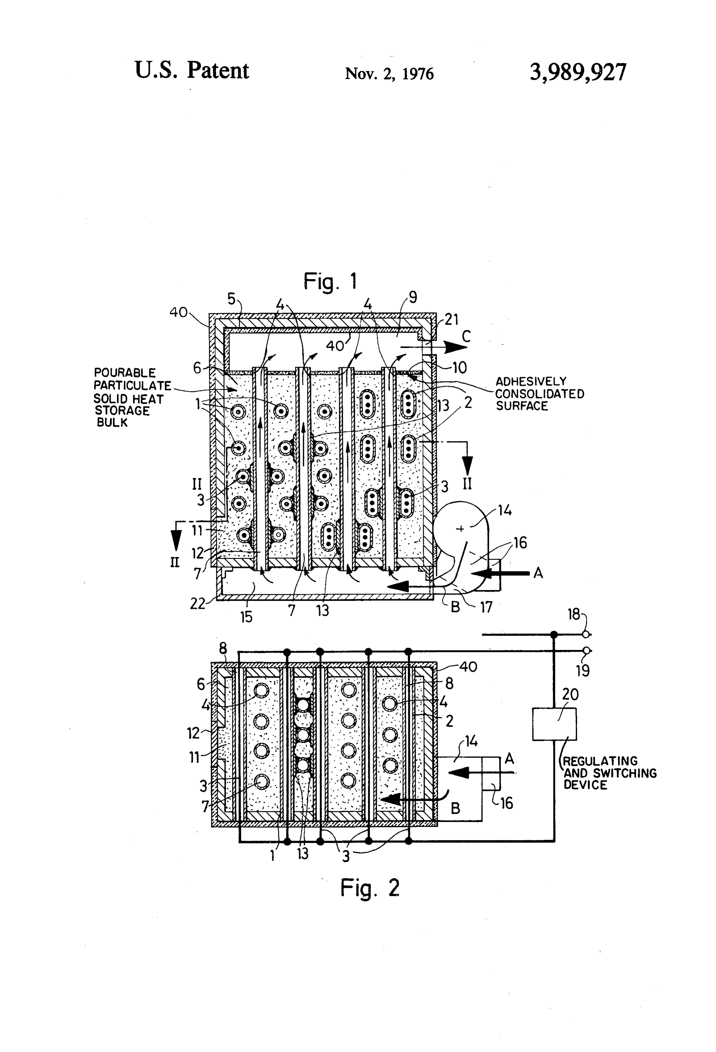
the invention the thermal storage medium comprises a 35 One embodiment of the invention is explained here bulk in which the product of specific heat and bulk inbelow by reference to the accompanying drawing in density of the solids material is at least 0.7 kcal/Cdm', which it is shown purely diagrammatically and in which the specific heat of the solids material being at least FIG. 1 is a vertical section through a storage heater 0.12 kcal/C kgfor the bulk density of the solids mate arranged for direct space heating with warm or hot air rial amounting to at least 2.5 kgf/dm'. and
It will be evident that the invention enables the entire 40 FIG. 2 is a horizontal section along the line II-II available container volume to be utilized for thermal according to FIG. 1.
storage while the choice of material according to the The embodiment illustrated in the drawing refers to a invention ensures that thermal conduction in the ther unit which can be used for space heating by directly mal storage material is substantially improved into its heating the room air. The bottom of a container 5 of farthest corners so that heating-up times and thermal 45 steel plate is provided with apertures into which verti discharge times can be substantially reduced. cally positioned tubes of suitable cross-section are in According to a further suitable embodiment of the serted to function as guide ducts for a gaseous heat invention the thermal storage medium may advanta extraction medium and are welded to the bottom plate geously comprise iron granulate in bulk form. Substan 50 of the container 5. As may be seen by reference to the tial cost reductions can be surprisingly achieved if the horizontal section of FIG. 2 the tubes are distributed thermal storage medium takes the form of a bulk, part throughout the container 5 so that a uniform heat dis of which comprises minerals that contain heavy metals, tribution may be expected over the horizontal cross and the said bulk may advantageously contain ground section of the container -5. To this end the tubes 4, overburden rock obtained in ore mining. To this end 55 which are constructed of metal, preferably iron and hematite minerals have been found particularly advan function as guide duct for the gaseous heat extraction tageous as thermal storage medium. medium are already sufficiently located in their vertical A storage heater according to the invention is also extension, usually by welding to the bottom part of the prefectly suitable to function as thermal energy source container 5.
for warm water heating systems, the gaseous heat ex As may be seen more particularly by reference to traction medium instead of blowing into a room which 60 FIG. 2 the ducts 1 or 2 respectively for heating ele is to be heated being supplied via a suitably constructed ments 3 are disposed transversely to the guide ducts 4 forced circulation duct with assisted circulation in the for the thermal extraction medium which is symbolized form of one or more fans, to be supplied to a down by the arrows A, B and C. As may be seen by reference stream disposed heat exchanger from which the said 65 to the upper part of the vertical section according to heat extraction medium is returned to the entry of the FIG. 1 the ducts 1 or 2 respectively for the heating guide ducts which extend through the thermal storage elements are also constructed as metal tubes and are medium. In a construction of this kind it is possible for disposed without physical contact and therefore with the feed and return of the heat delivery system which out thermally conductive contact with the guide ducts
Page 4
4 for the thermal extraction medium. This arrangement 5 not only with respect to its oppositely disposed side may be provided over the entire vertical section of the walls but more particularly with regard to transversely storage heater volume the construction of which will be disposed walls. The container wall 5 constructed in this described hereinbelow, more particularly if no value is manner and the intersectingly joined tubes secured placed on a particularly low thermal inertia in a storage 5 thereon by means of welding or soldering form a load heater according to the invention. In this case and as bearing, rigid and torsional resistance skeleton which may be seen in FIG. 2, the tubes 1 or 2 respectively, enables the walls of the container and the tubes to be which form the ducts for accommodating the heating constructed of particularly thin material thus enabling elements 3, are inserted into corresponding recesses of substantial cost savings to be achieved quite apart from the side walls of the container 5 and are secured 10 the substantial reduction of the large weight which is thereat. To this end the horizontally disposed ducts for frequently detrimental, particularly in larger units. , receiving the heating elements 3 may be welded to the The heat storage container 6 in the form of packed wall of the container 5. In this way they simultaneously. solids, is introduced into the remaining interior space function as tie rods or compression bars which enable of the container 5. The said packed solids which are the container 5 to be constructed of relatively thin 15 preferably vibrated and/or tamped while being intro metal sheet thus leading to a substantial saving of prime duced may comprise a granule collection of small parti COStS. . . . . . .. cles, not secured relative to each other and having a By disposing the guide ducts for the gaseous heat good thermal storage capacity and consisting of miner extraction medium in vertical configuration it enables als containing heavy metals, more particularly packed the heating elements to be horizontally disposed so that 20 bulk containing ground overburden rock from ore pro the electrical connection thereof may be made from duction, preferably hematite minerials, with the possi one or both sides of the storage heater. The construc ble addition of iron granulate of the kind yielded as tive simplifications which are achievable thereby as waste in foundries. The packed solids bulk 6 may how regards the electrical equipment and maintenance re ever also comprise exclusively small cast iron beads in pair and exchange of heating elements are obvious. At 25 order to achieve a particularly high thermal storage the same time the supply of heat to the thermal storage co-efficient but it is preferably that the said beads are medium is rendered substantially more uniform as re then surrounded by mineral dust or for example metal gards local distribution. *- ",, : lic electrostatic filtration dust and that the spaces be FIG. 1 shows two different kinds of tubes to explain tween the beads are filled with this material. The maxi that those for accommodating the heating elements 330 mum particle size of the thermal storage material 6 is may have a different cross-section, namely simple cir 1.5 mm, at least 5 percent by weight comprising pulver - cular tubes 1 in the zone of the left half of the vertical ized material with particle sizes of less than 0.2 mm in section for accommodating one heating element 3 in order to improve binding and filling intestices in the the interior 8 of the said tube and so called flat tubes 2 interests of increasing the thermal storage co-efficient. on the right half of the vertical section for accommo-35 In this connection it should be mentioned that this is a dating a plurality, for example three heating elements surprising effect because the addition of dust material 3. . . . m does not by any means enable the maximum bulkden As may be seen by reference to the lower vertical sity to be obtained. However, experience has shown section zone of FIG. 1, part of the tubes 1 or 2 respec that the thermal storage capacity of the entire packed tively for receiving the heating elements are in thermal 40 solids bulk which forms the thermal storage medium conductive contacts with the guide tubes 4 for the can be increased by the addition of such dust material thermal extraction medium in order to increase the against the opinion held by experts that the proportion thermal transfer of the thermal energy supplied by the of such dust material should not exceed 20 percent of heating elements 3 which, as shown diagrammatically the total weight of the bulk since substantial propor in FIG. 2 are connected by known conductors to the 45 tions of packed bulk material whose particle size ex busbars 18 and 19 of an electrical network, the electri ceeds approximately 0.2 mm has been shown by experi cal connections being of no significance to the inven ence to lead to a reduction of the pack weight and tion and being therefore not shown, the said supplied therefore to a substantial impairment of the thermal thermal energy being transferred by thermal radiation storage capacity.
and/or thermal conduction to the tubes 1 or 2 respec- 50 Experience has shown that a mineral granulate with tively and from there by thermal conduction to the the following composition is particularly advantageous thermal storage medium. 6, thus improving the inertia as thermal storage medium: iron more than 45 percent characteristics of the entire storage heater. To this end by weight, manganese less than 0.08 percent by weight, the corresponding tubes 1 or 2 respectively may be phosphorus less than 0.3 percent by weight, calcium directly welded to the tubes 4 with which they intersect 55 oxide less than 4.5 percent by weight, silicon dioxide by bearing upon each other but it has been found that more than 3.0 percent by weight and aluminum oxide a substantial increase of thermal transfer from the more than 0.4 percent by weight. tubes 1 or 2 respectively of the heating elements to the The material which is preferred for the thermal stor tubes 4 which carry the thermal extraction medium can age medium has the following composition: 65.90 per be achieved by interposing intermediate plates 13 to 60 cent by weight of iron, 0.03 percent by weight of man which on the one hand the tubes 1 or 2 respectively and ganese, 0.018 percent by weight of phosphorus, 0.10 on the other hand the tubes 4 are welded or are percent by weight of calcium oxide, mangesium oxide soldered if a material other than iron is used. traces, 4.70 percent by weight of silicon oxide, 0.49 This construction in which the tubes 1 or 2 respec percent by weight of aluminum oxide, 0.01 percent by tively are welded or soldered to the tubes 4, which may 65 weight of chromium, 0.01 percent by weight of copper, also be provided over the entire cross-sectional height 0.034 percent by weight of titanium dioxide, and 0.04 by contrast to the illustration of FIG. 1, also offers the percent by weight of carbon. Material of this kind is mechanical advantage of stiffening the entire container commercially available with the finished desired parti
Page 5
cle composition as broken bulk material under the need for making allowances of storage bricks being name of iron glance. However, other kinds of bulk disposed in layers and while substantially avoiding any material can be employed provided they have a specific unnecessary joints between them. heat of at least 0.12 kcal/ C kgf and, given a suitable. In order to still further increase the thermal storage bulk density, a product of specific heat and bulk den capacity of a storage heater according to the invention sity of at least 0.7 kcal/C dm or a product of specific with given external dimensions a further and not yet heat and bulk density of at least a same value, given a anticipated idea of the invention is characterized in bulk density of at least 2.5 kgf/dm and a suitable spe that the outside of the container for the thermal storage cific heat. According to experience this is made possi medium is provided with a thermal barrier 40 of lower ble by minerals containing heavy metals, iron-bearing O thermal conductivity and/or higher thermal radiation minerals obtained in iron ore winning with or without capacity than that of the material of which the con the addition of pure iron granulate, for example cast tainer is constructed. If an increase of the thermal stor iron beads of suitable particle size composition are age capacity is not required the external dimensions of preferred as the cost of such material is low. n the storage heater according to the invention can be It has also been found particularly advantageous to 15 reduced by means of this inventive development while employ a granulate with a maximum particle size of the thermal storage capacity remains the same. In each approximately 1.5 mm, preferably covering the range case the thermal losses to the ambient atmosphere are between 0.3 mm to approximately 1.25 mm. It has also substantially reduced by the thermal barrier employed been found advantageous if the granulate contains at in accordance with the invention. According to the least 5 percent by weight of pulverized, material with 20 invention the thermal barrier may comprise aluminum particle sizes of less than 0.2 mm. A proportion of the oxide and/or zirconium oxide. It has been surprisingly. pulverized material equivalent to a maximum of 20 found possible for the material, which forms the ther percent by weight of the granulate is to be preferred. A mal barrier to be applied by coating or spraying to a further improvement of the thermal storage capacity thickness of up to approximately 1.0 mm on the outside can be achieved in simple and economical manner if 25 of the container for the thermal storage medium and/or the solids bulk is vibrated and/or tamped while it is the wind chamber side surface of the wind chamber introduced into the container. . .. wall. As a result the storage capacity can be increased The upwardly orientated surface of the thermal stor still further for given dimensions than would normally age material pack 6 is consolidated by thermally resis 30 correspond to the saving of avoided heat losses because tant adhesive joining in order to form a surface which is the use of the thermal barrier according to the inven protected against the discharge of very fine dust parti tion enables the stratum thickness of the insulating cles from the thermal storage material 6. A mineral material to be reduced for a given external temperature glue, preferably containing water glass is used for adhe of the wall of the container for the thermal storage sive joining and may be prepared, for example on the medium by using the thermal barrier according to the basis of finely ground mineral dust of the thermal stor 35 invention, this reduction permitting the volume of the age material 6. Between the thermally resistant adhe thermal storage medium to be increased. sive joining 10 of the intrinsically consolidated surface Like the external surface of the container 5 for the of the thermal storage material 6, which could also heat storage medium, which is also not shown in detail, have been replaced by a suitably constructed cover 40 the surface of the wall of the wind chamber 9 nearest to plate, and the internal wall of the covering part of the the interior thereof may be provided with a heat barrier container 6 there is formed a wind chamber 9 which 40, applied cold, comprising a covering which is ap communicates with external atmosphere through one. plied on the insulating material stratum on the con or two discharge apertures 21 for the thermal extrac tainer wall and consists of a mineral glue, for example tion medium. Apart from a mixing of the individual 45 water glass or bonded aluminum oxide. Apart from a heated part streams of gaseous heat extraction medium particularly low thermal conductivity this material has discharged from the individual guide tubes 4 in the a surprisingly low thermal radiation absorption capac wind chamber 9 and therefore accompanied by a tem ity so that by applying it relatively thinly it is possible to perature compensation for any local temperature irreg achieve a substantial reduction of the wall thickness of ularities between the individual part flows there is also conventionally employed material for the thermal insu smoothing of the flow so that eddies or the like are 50 lation of the container 5 for the thermal storage me substantially avoided when the flow exits from the wind dium 6, given the same temperature of the external chamber 9 into the external atmosphere which is to be surface and identical temperature of the internal sur directly heated. face and therefore the same temperature drop or, given Furthermore, the bottom wall of the container 5 55 the same wall thickness of conventional insulating ma contains a discharge aperture 11 for the pourable heat terial under these conditions enables a lower tempera storage material 6, the said aperture being sealed in ture to be achieved on the external surface of the con suitable manner by a lid 12. If the thermal storage tainer insulation thus resulting in a substantial improve material 6 or the tubes 1, 2 or 4 have to be changed in ment of reliability and thermal economy. the event of repairs which may become necessary the 60 The circulation of the thermal extraction medium is thermal storage material 6 may be rapidly and conve formed as follows:
niently removed through this aperture. The thermal Part of the ambient air is supplied via the suction storage medium may be subsequently introduced in the socket 16 to a fan 14 which accelerates the said air and same simple and convenient manner the special inven delivers it through the inlet duct 17 into an inlet cham tive choice of the said pourable solids material also 65 ber 15 which is disposed below the bottom wall of the offering the advantage of particularly good filling of container 5 for the thermal storage medium 6. The inlet even the smallest cavities in the interior of the con chamber comprises an upright plate 22 which is se tainer 5, where such cavities can never be completely cured on the bottom of the container 5 by means of avoided for reasons of construction and without the angle irons which are not referenced but illustrated.
Page 6
Any desired other known construction of an inlet places of human habitation; the product of the specific chamber may also be employed to this end. The ambi heat of the solid and the bulk density of the pourable ent air flows into the fan 14, which is preferably detach bulk being at least 0.7 kcal/Cdm', the specific heat of ably secured on the container 5 for the thermal storage the solid being at least 0.12 kcal/C kgf and the bulk material 6, in the direction indicated by the arrow A density of the pourable bulk being at least 2.5 kgf/dm. and the air accelerated in the said fan flows into the 2. A storage heater as claimed in claim 1 wherein the inlet chamber 15 in the direction indicated by the heat storage medium comprises a bulk packing of a arrow B. From the inlet chamber 15 the air flows granulated mineral containing iron. through the interior spaces 7 of the air ducts 4 into the 3. A storage heater as claimed in claim 1, wherein the wind chamber 9 while abstracting heat from the sur 10 thermal storage medium comprises ground overburden rounding heat storage materials 6 while flowing rock obtained from winning iron ore.
through the ducts 4. The air flow is smoothed as al 4. A storage heater as claimed in claim 3 wherein the ready described in the wind chamber 9 and this is ac thermal storage medium contains hematite minerals. companied by simultaneous temperature exchange and 5. A storage heater as claimed in claim 4 wherein the a discharge of warm or hot air through the exit duct 21 15 thermal storage medium comprises a mineral granulate as indicated by the arrow C. with the following composition: The numeral 20 of FIG. 2 shows a regulating and Iron more than 45 percent by weight, manganese less switching device of known construction for supplying than 0.08 percent by weight, phosphorus less than electrical energy from the bus bars 18, 19 to the heat 0.3 percent by weight, calcium oxide less than 4.5 ing elements 3, the regulating and switching device 20 percent by weight, silicon dioxide more than 3.0 receiving the measured values and control pulses from percent by weight and aluminum oxide more than measuring transducers disposed in suitable manner but 0.4 percent by weight.
not shown since they do not affect the invention. 6. A storage heater as claimed in claim.4 wherein the It is clear that the invention may be employed for thermal storage medium comprises a mineral granulate purposes other than direct space heating with air. For 25 of the following composition:
example a close circulation may be provided with suit 65.90 percent by weight of iron, 0.03 percent by able piping or the like between the arrows C and A, weight of manganese, 0.018 percent by weight of more particularly for industrial heating systems in phosphorus, 0.10 percent by weight of calcium which specific program controlled heating processes oxide, magnesium oxide traces, 4.70 percent by have to be provided, a heat exchanger for gaseous or 30 weight of silicon dioxide, 0.49 percent by weight of liquid medium on the secondary side being connected aluminum oxide, 0.01 percent by weight of chro in such piping to function as heat consumer. Instead of mium, 0.01 percent by weight of copper, 0.034 the air which is employed in the described embodiment percent by weight of titanium dioxide and 0.06 it is also possible for a different gaseous heat extraction 35 percent by weight of carbon. medium to be provided. Furthermore, a storage heater 7. A storage heater as claimed in claim 4, wherein the unit according to the invention which operates with air thermal storage medium is a granulate having a maxi as heat extraction medium and has a forced circulation mum particle size of approximately 1.5 mm. for air via a flow duct, not shown adapted to connect 8. A storage heater as claimed in claim 7 wherein the the hot exit 21 to the inlet socket of the fan 14 and particle size is between approximately 0.3 to approxi which incorporates a heat exchanger for primary bias 40 mately 1.25 mm.
ing with hot air and secondary conduction of water, 9. A storage heater as claimed in claim 7 wherein the may be used as heating energy transmitter for a warm granulate contains at least 5 percent by weight of pull water heating system of conventional kind when such a verized material with particle sizes of less than 0.2 mm. unit according to the invention may be employed in 10. A storage heater as claimed in claim 9 wherein place of a flame fired boiler or in place of a storage 45 the granulate contains a maximum of 20 percent by heater unit with a water store of large volumetric ca weight of such sized pulverized material. pacity. 11. A storage heater as claimed in claim 1 wherein a Although the invention is described merely by refer surface of the thermal storage medium is exposed to ence of one preferred application in purely exemplified air, the exposed surface of the thermal storage medium form, it is not confined thereto. The expert has many 50 being intrinsically consolidated by heat resistant adhe and varied possibilities to adapt the invention to the sive joining.
conditions or requirements of each individual case by 12. A storage heater as claimed in claim 11 wherein adopting a different combination of its features and/or a mineral glue is used for adhesive joining. exchanging them for identical means without departing 13. A storage heater as claimed in claim 12 wherein from the scope of the invention. the mineral glue contains water glass. I claim: 14. A storage heater as in claim 12 wherein the min 1. A storage heater for heating a gaseous heat extrac eral glue contains a slurry of pulverized thermal storage tion medium, the heater comprising: a container having medium.
walls formed of a heat resistant material; at least one 15. A storage heater as in claim 12 wherein the min guide duct, in the form of a tube extending through the 60 eral glue is applied to a thickness of approximately 1 container, for carrying gaseous heat extraction me mm on the surface of the thermal storage material. dium; a thermal storage medium within the container, 16. A storage heater as in claim 11, comprising a means associated with the container for supplying heat plurality of guide ducts for the gaseous medium passing to the storage medium, the medium comprising heavy vertically through the storage medium and a plenum metal-bearing minerals and being in the form of a pour 65 wind chamber within the heater, located above the able heavy metal-bearing minerals and being in the storage medium and in fluid flow connection with all of form of a pourable bulk of particulate solids and being the guide ducts, wherein one boundary surface by the suitable for directly contacting air to be heated for wind chamber is formed of the adhesively joined sur
Page 7
face of the thermal storage medium and which forms 22. A storage heater as claimed in claim 20 wherein the top surface of the medium. the duct for accommodating the heater element is con 17. A storage heater as in claim 1 wherein the con structed as a tube of heat resistant material of high tainer for the thermal storage medium is provided on its 5 thermal conductivity which is inserted into the con exterior with a thermal barrier of lower thermal con tainer and whose interior is accessible from the outside ductivity and higher thermal radiation capacity than of the said container.
the material of the container. 23. A storage heater as in claim 20 wherein the con 18. A storage heater as claimed in claim 17 wherein tainer is constructed of metal. the thermal barrier contains aluminum oxide. 24. A storage heater as in claim 23, wherein the O container and the ducts are constructed of metal and 19. A storage heater as in claim 17, wherein the material which forms the thermal barrier is a coating the ducts are connected to the wall of the container by having a thickness of up to approximately 1.0 mm on means selected from the group consisting of welding the outside of the container for the thermal storage and soldering.
medium. 25. A storage heater as in claim 20, wherein the 20. A storage heater as in claim 1, wherein said 15 heating element duct is disposed in thermally conduc means for supplying heat to the thermal storage me tive contact to at least a portion of the guide duct. dium includes a heating element duct disposed approxi 26. A storage heater as in claim 25, wherein the guide mately horizontally through the container and said at duct and the heating element duct are each connected least one guide duct for the gaseous thermal extraction to an intermediate plate which enlarges the thermal medium being disposed approximately vertically 20 transfer surface area between them.
through the container, the heating element duct and 27. A storage heater as in claim 1 wherein the con the guide duct both being surrounded around their tainer comprises a wind chamber in communication circumference and along the length extending within with one end of said at least one guide duct, said wind the container by the thermal storage medium. 25 chamber being provided on its interior surface with a 21. A storage heater as in claim 20, wherein one of thermal barrier of lower thermal conductivity and said ducts is constructed as a compression bar, or tie higher thermal radiation capacity than the material of rod, adapted to connect two oppositely disposed walls the container.
of the container. k ck ck sk
Provenance
- Collection
- Cited prior art
- Original PDF
- patentimages.storage.googleapis.com →
- Filed
- 1973-08-06
- Pages
- 7
- Method
- pdftotext (the PDF's own text layer) + pdftoppm 300dpi page scans
- Source
- Google Patents bibliographic record
- Granted
- 1976-11-02
- Inventors
- Georg Otto Erb
- Transcribed from
- patentimages.storage.googleapis.com →