patent · US4441318
Method and apparatus for obtaining work from heat energy
10 April 1984
Page 1 — bibliographic record
United States Patent (19) 11 4,441,318 Theckston 45) Apr. 10, 1984 54 METHOD AND APPARATUS FOR 56) References Cited OBTAINING WORK FROM HEAT ENERGY U.S. PATENT DOCUMENTS 76 Inventor: Alexander Theckston, 10 Emden 4,235,075 11/1980 Erb ................................... 60/325 X Crescent, Mulgrave, 3170, Victoria, FOREIGN PATENT DOCUMENTS
Australia 46-42523 12/1971 Japan ..................................... 60/.530 (21) Appl. No.: 389,065 176510 3/1922 United Kingdom.................. 60/530
22 Filed: Jun. 16, 1982 Primary Examiner-Allen M. Ostrager Assistant Examiner-Stephen F. Husar
Related U.S. Application Data Attorney, Agent, or Firm-Bernard, Rothwell & Brown 63 Continuation-in-part of Ser. No. 66,232, Aug. 13, 1979, 57 ABSTRACT abandoned. The present invention provides a method of obtaining 30 Foreign Application Priority Data mechanical work from heat energy comprising heating a body of metal or metal alloy confined within a pres
Aug. 14, 1978 AU Australia .................................... 5495 sure vessel having a coefficient of volume expansion less than said body of metal or metal alloy contained 51) Int. Cl. ................................................ FO3G 7/06 therein to generate an increase in pressure within the 52 U.S. Cl. ........................................ 60/527; 60/530; vessel and causing the increased pressure to move a load
60/.530, 641.8 16 Claims, 3 Drawing Figures
assass
Saraasa 22
ZZZZZZ
Page 2
Drawing sheet — no readable text.
Page 3
Drawing sheet — no readable text.
Page 4
produce work cyclically during the heating intervals. In
METHOD AND APPARATUS FOR OBTAINING this case the pressure generating device comprised of WORK FROM HEAT ENERGY said body of metal or metal alloy and the pressure vessel may be one of a plurality of similar devices operated
FIELD OF THE INVENTION both simultaneously or cyclically out of phase with one This application is a continuation-in-part of applica another to produce a substantially continuous work tion Ser. No. 066,232, filed Aug. 13, 1979, now aban output.
doned. Said body of metal or metal alloy may be heated This invention provides a novel manner and means O and/or cooled by direct thermal transfer through the for obtaining useful mechanical work from heatenergy. pressure vessel and/or by heat exchange between an The invention is particularly, but not exclusively external heat reservoir and said body. applicable to derivation of work from heat energy Said increased pressure in the pressure vessel may be sources of low concentration, such as solar radiation caused to move the load by movement of a piston or and waste heat from industrial processes and machines. other pressure sensitive element in response to said The work so derived may be used for any of a variety of 15 increased pressure and said element may be returned to purposes but one particularly useful application of the its original position on cooling of said body of metal or invention is in the conversion of solar energy to electri metal alloy by energy storage means, for example spring cal power. means, or, in the case where a plurality of similar pres SUMMARY OF THE INVENTION sure generating devices are operated cyclically, by ex 20 pending part of the work produced by one device to
According to the invention there is provided a impart a return movement to the respective element of method of obtaining mechanical work from heatenergy another device.
comprising heating a body of metal or metal alloy con The work done by the method of the present inven fined within a pressure vessel having a co-efficient of 25 tion may constitute part or all of a work input for any volume expansion less than said body of metal or metal work consuming device or process. The invention spe alloy contained therein thereby to generate an increase cifically extends to a process for generating electrical in pressure within the vessel and causing the increased power wherein an electrical power generator receives a pressure to move a load thereby to do work. work input by performance of the above defined PREFERRED ASPECTS OF THE INVENTION 30 method.
The invention also extends to apparatus for deriving
Preferably the metal or metal alloy is in a liquid or mechanical plastic state throughout the heating step or passes from of metal or worka from heat energy comprising a body metal alloy confined within a pressure plastic to liquid state during heating. vessel having a coefficient of volume expansion less Preferably said metal or metal alloy has a coefficient than said body of metal or metal alloy confined therein of volume expansion greater than 10x10-6 ml/ml/K. 35 and and a melting point or melting range such that the liqui load in response to an increase inapparatus means adapted in use of the to move a pressure within the dus temperature does not exceed 939 K. More particu pressure vessel.
larly it is preferred that said metal or metal alloy have a The apparatus may also include means to apply heat coefficient of volume expansion within the range to said body of metal or metal alloy. Such means may
comprise means to collect melting point or melting range such that the liquidus heat energy from such radiation solar radiation and to apply temperature does not exceed 550 K. and the solidus or metal alloy. to such body of metal temperature is not less than 200 K.
Preferably further said metal or metal alloy has a BRIEF DESCRIPTION OF THE VIEWS OF THE thermal capacity (specific heat) falling within the range 45 DRAWINGS
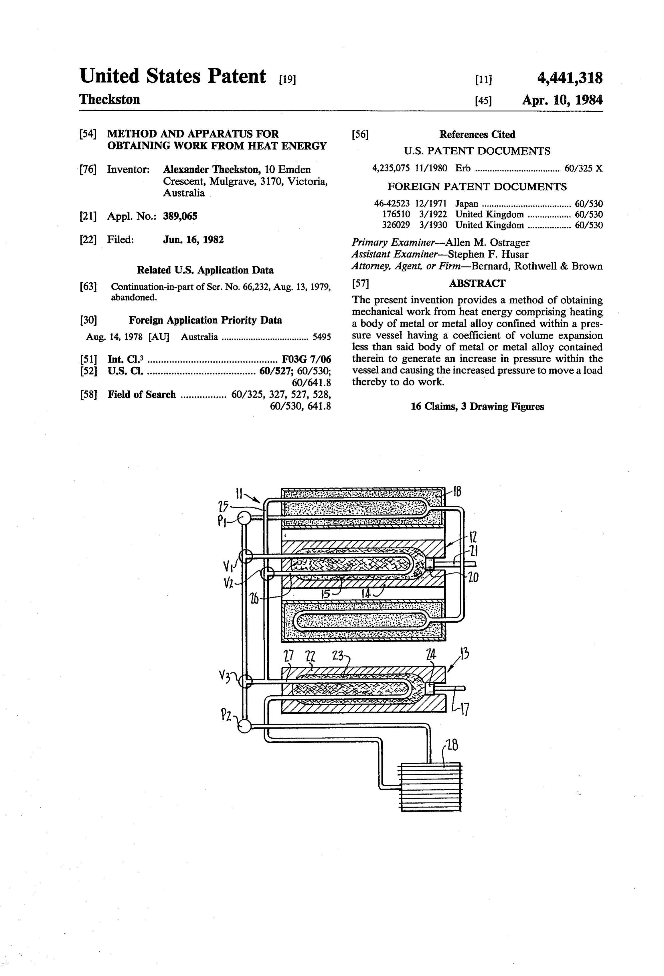
Said body may be comprised of any one or more of In order that the invention may be more fully ex the metals comprising the Group 1A metals and magne plained one particular type of heat conversion device, sium, zinc, calcium, aluminum, manganese, strontium, and the manner in which this type of device may be cadmium, indium, tin, mercury, barium, lead or their 50 applied to the conversion of solar energy to electrical alloys. power, will be described with reference to the accom The pressure vessel may be made of steel or prefera panying drawings in which:
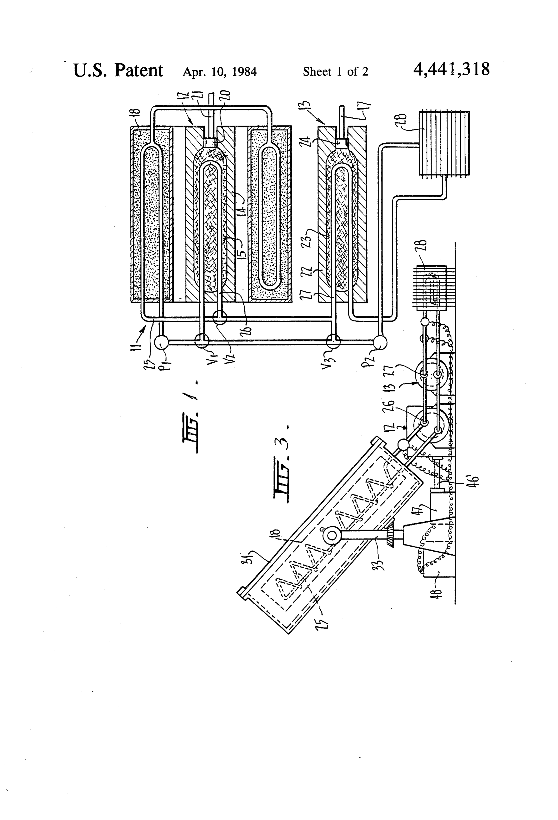
bly ceramic materials or metals such as tungsten, mo FIG. 1 is a diagrammatic representation of the heat lybdenum, titanium or a low expansion alloy such as conversion device,
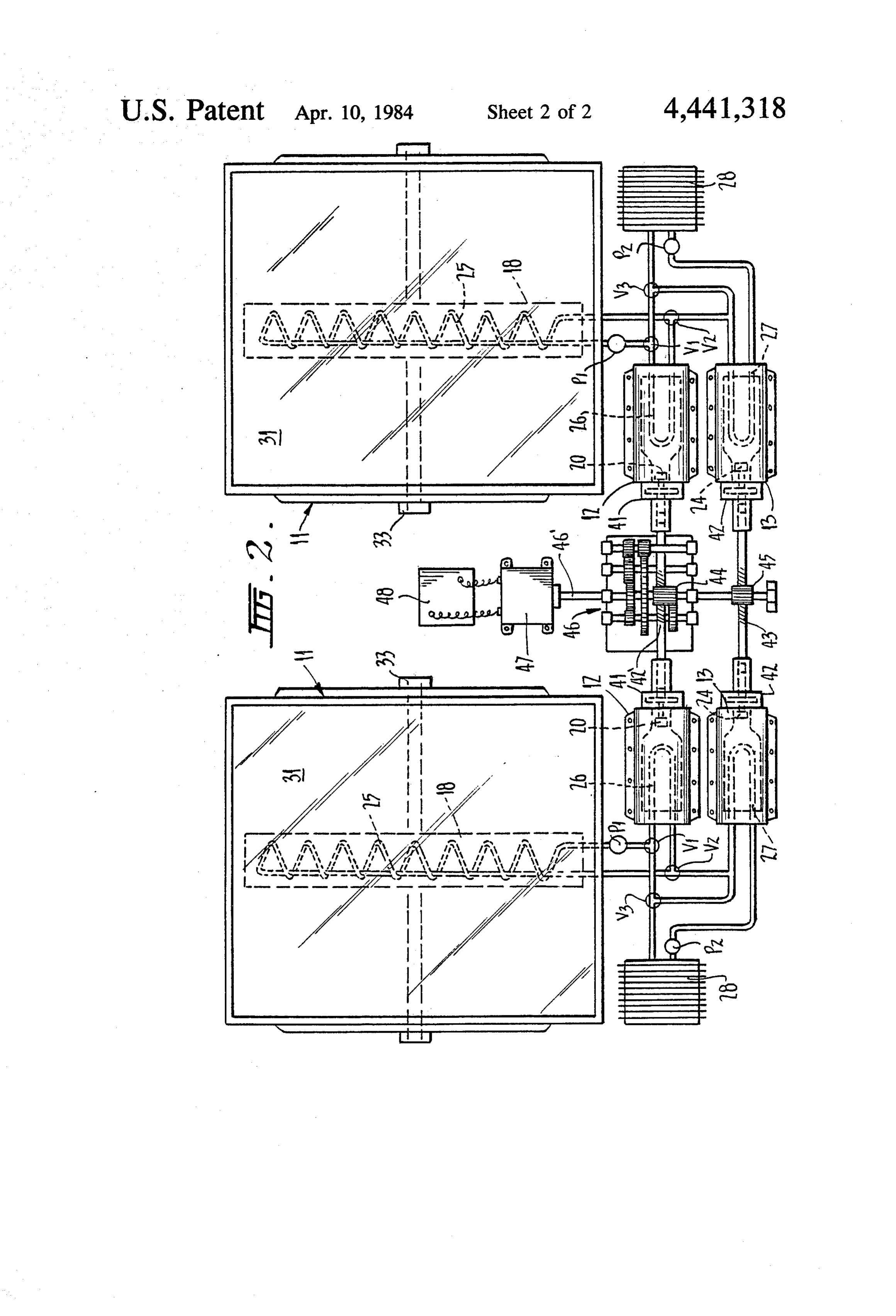
Invar, Kovar or Nilo K. Where, for reasons of cost, the 55 FIG. 2 is a schematic plan view of equipment incor pressure vessel is made of steel or of a low expansion porating a pair of such devices and capable of convert alloy such as Invar, Kovar or Nilo K, a thermal barrier ing solar energy to electrical power, and layer is introduced between the liquid metal of the core FIG. 3 is a schematic side elevation of the equipment and the pressure vessel walls, because these materials shown in FIG. 2.
have higher thermal conductivities than ceramic mate DETAILED DESCRIPTION WITH RESPECT TO rials or tungsten, molybdenum or titanium and, in the THE DRAWINGS absence of the thermal barrier layer, considerable en ergy could be expended in heating the material of which The heat conversion device illustrated in FIG. 1 is the pressure vessel is made and in conduction losses denoted generally as 11. It comprises a main high pres through the pressure vessel walls to the environment. 65 sure generator unit 12 and an auxiliary or low pressure Said body of metal or metal alloy may be heated generator unit 13. Main unit 12 comprises a cylindrical during spaced time intervals and be cooled or allowed pressure vessel 14 charged with a body of liquid metal to cool during the intervening time intervals so as to 15 which will be termed the "core' of the unit. This
Page 5
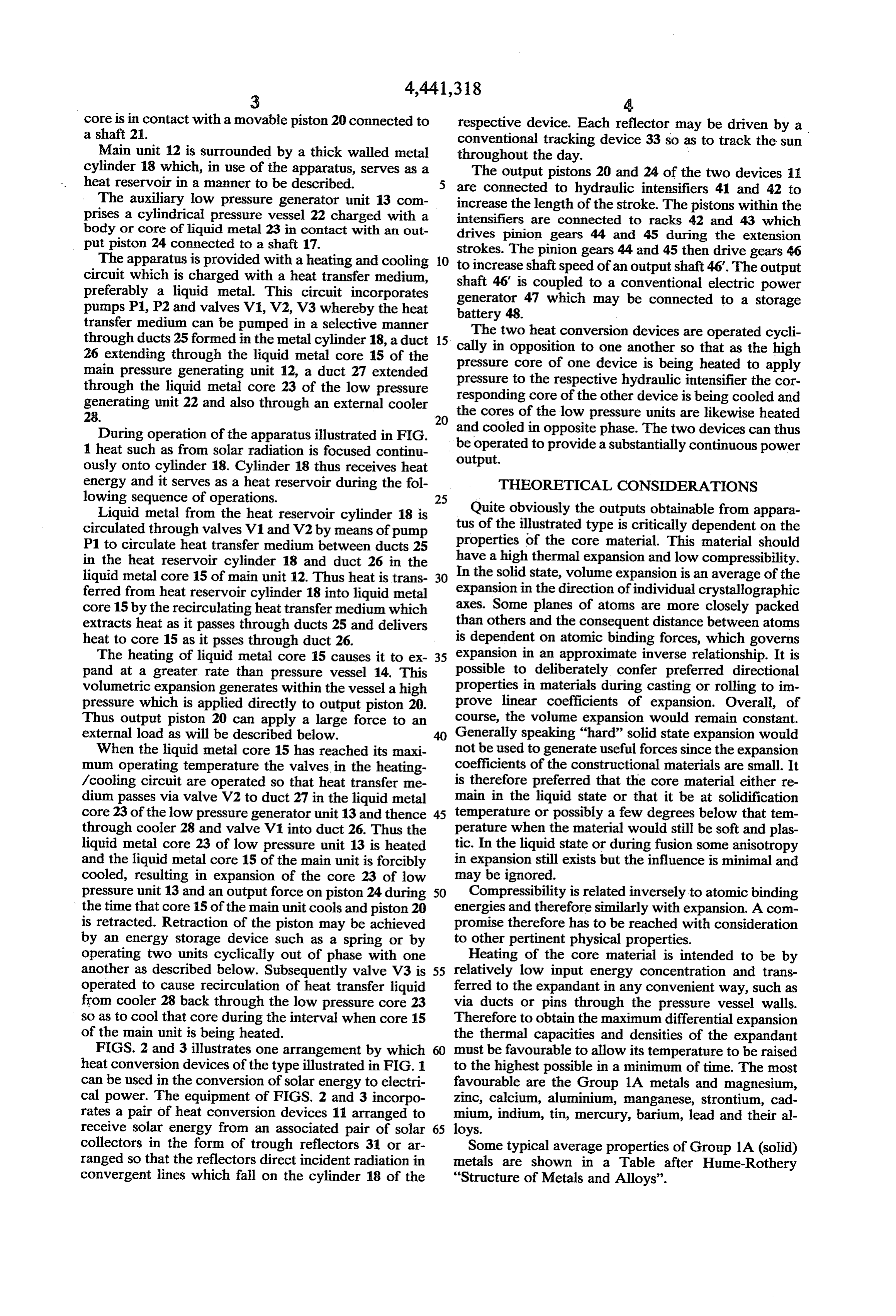
core is in contact with a movable piston 20 connected to respective device. Each reflector may be driven by a a shaft 21. conventional tracking device 33 so as to track the sun Main unit 12 is surrounded by a thick walled metal throughout the day.
cylinder 18 which, in use of the apparatus, serves as a The output pistons 20 and 24 of the two devices 11 heat reservoir in a manner to be described. are connected to hydraulic intensifiers 41 and 42 to The auxiliary low pressure generator unit 13 com increase the length of the stroke. The pistons within the prises a cylindrical pressure vessel 22 charged with a intensifiers are connected to racks 42 and 43 which body or core of liquid metal 23 in contact with an out drives pinion gears 44 and 45 during the extension put piston 24 connected to a shaft 17. strokes. The pinion gears 44 and 45 then drive gears 46 The apparatus is provided with a heating and cooling 10 to increase shaftspeed of an output shaft 46. The output circuit which is charged with a heat transfer medium, shaft 46' is coupled to a conventional electric power preferably a liquid metal. This circuit incorporates generator 47 which may be connected to a storage pumps P1, P2 and valves V1,V2, V3 whereby the heat battery 48.
transfer medium can be pumped in a selective manner The two heat conversion devices are operated cycli through ducts 25 formed in the metal cylinder 18, a duct 15 cally in opposition to one another so that as the high 26 extending through the liquid metal core 15 of the pressure core of one device is being heated to apply main pressure generating unit 12, a duct 27 extended pressure to through the liquid metal core 23 of the low pressure responding the core respective hydraulic intensifier the cor of the other device is being cooled and generating unit 22 and also through an external cooler the cores of the low pressure units are likewise heated
During operation of the apparatus illustrated in FIG. and cooled in opposite phase. The two devices can thus be operated to provide a substantially continuous power 1 heat such as from solar radiation is focused continu ously onto cylinder 18. Cylinder 18 thus receives heat output.
energy and it serves as a heat reservoir during the fol THEORETICAL CONSIDERATIONS
Liquid metal from the heat reservoir cylinder 18 is Quite obviously the outputs obtainable from appara circulated through valves V1 and V2 by means of pump tus of the illustrated type is critically dependent on the P1 to circulate heat transfer medium between ducts 25 properties of the core material. This material should in the heat reservoir cylinder 18 and duct 26 in the have a high thermal expansion and low compressibility. liquid metal core 15 of main unit 12. Thus heat is trans 30 In the solid state, volume expansion is an average of the ferred from heat reservoir cylinder 18 into liquid metal expansion in the direction of individual crystallographic core 15 by the recirculating heat transfer medium which axes. Some planes of atoms are more closely packed extracts heat as it passes through ducts 25 and delivers than others and the consequent distance between atoms heat to core 15 as it psses through duct 26. is dependent on atomic binding forces, which governs The heating of liquid metal core 15 causes it to ex 35 expansion in an approximate inverse relationship. It is pand at a greater rate than pressure vessel 14. This possible to deliberately confer preferred directional volumetric expansion generates within the vessel a high properties in materials during casting or rolling to in pressure which is applied directly to output piston. 20. prove linear coefficients of expansion. Overall, of Thus output piston 20 can apply a large force to an course, the volume expansion would remain constant. external load as will be described below. Generally speaking "hard' solid state expansion would When the liquid metal core 15 has reached its maxi not be used to generate useful forces since the expansion mum operating temperature the valves in the heating coefficients of the constructional materials are small. It /cooling circuit are operated so that heat transfer me is therefore preferred that the core material either re dium passes via valve V2 to duct 27 in the liquid metal main in the liquid state or that it be at solidification core 23 of the low pressure generator unit 13 and thence 45 temperature or possibly a few degrees below that tem through cooler 28 and valve V1 into duct 26. Thus the perature when the material would still be soft and plas liquid metal core 23 of low pressure unit 13 is heated tic. In the liquid state or during fusion some anisotropy and the liquid metal core 15 of the main unit is forcibly in expansion still exists but the influence is minimal and cooled, resulting in expansion of the core 23 of low may be ignored.
pressure unit 13 and an output force on piston 24 during 50 Compressibility is related inversely to atomic binding the time that core 15 of the main unit cools and piston 20 energies and therefore similarly with expansion. A com is retracted. Retraction of the piston may be achieved promise therefore has to be reached with consideration by an energy storage device such as a spring or by to other pertinent physical properties. operating two units cyclically out of phase with one Heating of the core material is intended to be by another as described below. Subsequently valve V3 is 55 relatively low input energy concentration and trans operated to cause recirculation of heat transfer liquid ferred to the expandant in any convenient way, such as from cooler 28 back through the low pressure core 23 via ducts or pins through the pressure vessel walls. so as to cool that core during the interval when core 15 Therefore to obtain the maximum differential expansion of the main unit is being heated. the thermal capacities and densities of the expandant FIGS. 2 and 3 illustrates one arrangement by which 60 must be favourable to allow its temperature to be raised heat conversion devices of the type illustrated in FIG. 1 to the highest possible in a minimum of time. The most can be used in the conversion of solar energy to electri favourable are the Group 1A metals and magnesium, cal power. The equipment of FIGS. 2 and 3 incorpo zinc, calcium, aluminium, manganese, strontium, cad rates a pair of heat conversion devices 11 arranged to mium, indium, tin, mercury, barium, lead and their al receive solar energy from an associated pair of solar 65 loys.
collectors in the form of trough reflectors 31 or ar Some typical average properties of Group 1A (solid) ranged so that the reflectors direct incident radiation in metals are shown in a Table after Hume-Rothery convergent lines which fall on the cylinder 18 of the "Structure of Metals and Alloys'.
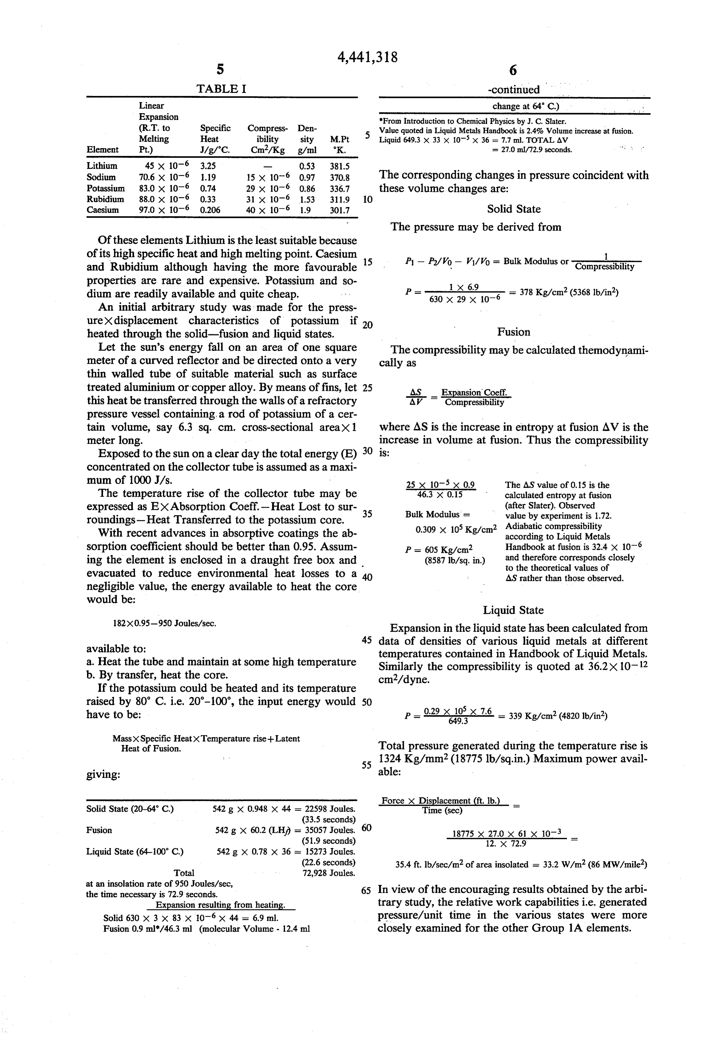
Page 6
TABLE I -continued
Linear change at 64 C.) Expansion From Introduction to Chemical Physics by J. C. Slater. (R.T. to Specific Compress- Den- 5 Walue quoted in Liquid Metals Handbook is 2.4% Wolume increase at fusion. Melting Heat ibility sity M.Pt Liquid 649.3 x 33 x 10' X 36 = 7.7 ml. TOTAL AV Element Pt.) J/g/°C. Cm/Kg g/ml K. = 27.0 ml/72.9 seconds. Lithium 45 x 10-6 3.25 m 0.53 381.5 a Sodium 70.6 x 10⁻⁶ i.19 15 x 10-6 0.97 370.8 The corresponding changes in pressure coincident with Potassium 83.0 x 10⁶ 0.74 29 x 10-6 0.86 336.7 these volume changes are: Rubidium 88.0 x 10⁻⁶ 0.33 31 x 10-6 1.53, 311.9 10
Caesium 97.0 x 10⁻⁶ 0.206 40 x 106 1.9 301.7 Solid State The pressure may be derived from
Of these elements Lithium is the least suitable because fits high specific of its high ific heat h and high g melting point.
int. Caesium 15 P - P/Wo - WAVO = Bulk Modulus or and Rubidium although having the more favourable Compressibility properties are rare and expensive. Potassium and so dium are readily available and quite cheap. Pe anal X 6.9
An initial arbitrary study was made for the press urex displacement characteristics of potassium if Fusion heated through the solid-fusion and liquid states.
Let the sun's energy fall on an area of one square The compressibility may be calculated themodynami meter of a curved reflector and be directed onto a very cally as thin walled tube of suitable material such as surface treated aluminium or copper alloy. By means offins, let 25 AS -- Expansion Coeff. this heat be transferred through the walls of a refractory AV Compressibility pressure vessel containing, a rod of potassium of a cer tain volume, say 6.3 sq. cm. cross-sectional areax 1 where AS is the increase in entropy at fusion AV is the meter long. increase in volume at fusion. Thus the compressibility Exposed to the sun on a clear day the total energy (E) 30 is:
concentrated on the collector tube is assumed as a maxi mum of 1000 J/s. 25 x 10-5 x 0.9 The AS value of 0.5 is the The temperature rise of the collector tube may be 46.3 x 0.15 calculated entropy at fusion expressed as EXAbsorption Coeff.-Heat Lost to sur- 35 Bulk Modulus = (after Slater). Observed value by experiment is 1.72.
roundings-Heat Transferred to the potassium core.
With recent advances in absorptive coatings the ab 0.309 x 10⁵ Kg/cm2 Adiabatic compressibility according to Liquid Metals sorption coefficient should be better than 0.95. Assum P = 605 Kg/cm2 Handbook at fusion is 32.4 x 10⁻⁶ ing the element is enclosed in a draught free box and (8587 lb/sq. in.)and therefore corresponds closely to the theoretical values of evacuated to reduce environmental heat losses to a 40 AS rather than those observed. negligible value, the energy available to heat the core would be:
Liquid State
Expansion in the liquid state has been calculated from 45 data of densities of various liquid metals at different available to:
temperatures contained in Handbook of Liquid Metals.
a. Heat the tube and maintain at some high temperature Similarly the compressibility is quoted at 36.2 x 10⁻¹² b. By transfer, heat the core. cm2/dyne.
If the potassium could be heated and its temperature raised by 80 C, i.e. 20-100, the input energy would 50 have to be: - 0.29 x649.3
MassXSpecific HeatXTemperature rise-Latent
Heat of Fusion. Total pressure generated during the temperature rise is 55 1324 Kg/mm2 (18775 lb/sq.in.) Maximum power avail giving: able:
Force X Displacement (ft. b.)
Solid State (20-64 C.) 542 g x 0.948 x 44 = 22598 Joules. Time (sec) (33.5 seconds)
Fusion 542 g x 60.2 (LHi = 35057 Joules. 60 18775 x 27.0 x 61 x 10-3 (51.9 seconds) 12. X 72.9
Liquid State (64-100° C) 542 g x 0.78 x 36 s 15273 Joules.
(22.6 seconds) 35.4 ft. 1b/sec/m2 of area insolated = 33.2 W/m2 (86 MW/mile)
at an insolation rate of 950 Joules/sec, 65 the time necessary is 72.9 seconds. In view of the encouraging results obtained by the arbi Expansion resulting from heating. trary study, the relative work capabilities i.e. generated Solid 630 x 3 x 83 x 10-6 x 44 = 6.9 ml. pressure/unit time in the various states were more Fusion 0.9 ml/46.3 ml (molecular Volume - 12.4 ml closely examined for the other Group 1A elements.
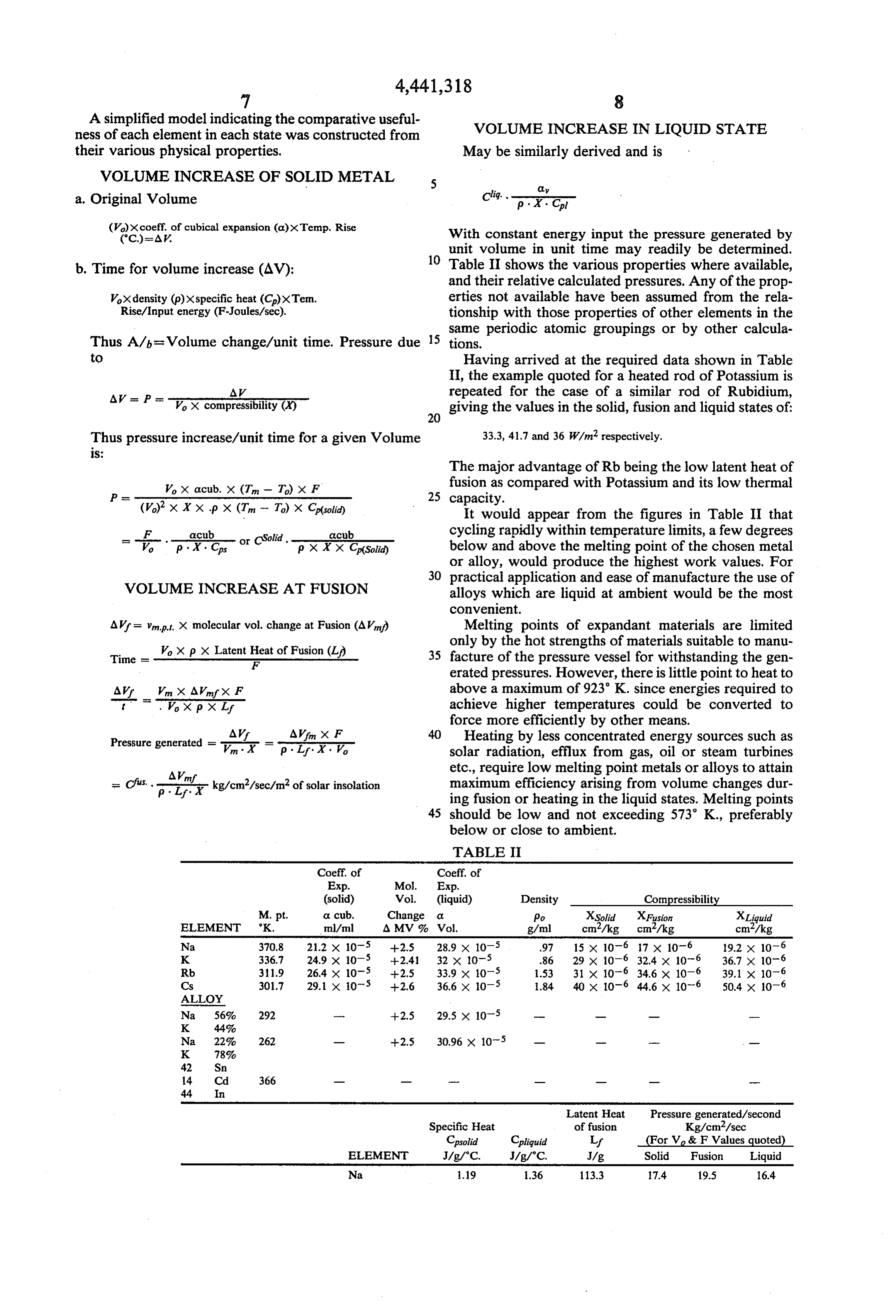
Page 7
A simplified model indicating the comparative useful ness of each element in each state was constructed from VOLUME INCREASE IN LIQUID STATE their various physical properties, May be similarly derived and is VOLUME INCREASE OF SOLID METAL 5 o Cliq. errorisms a. Original Volume p : X. Cl ()xcoeff. of cubical expansion (a)xTemp. Rise With constant energy input the pressure generated by
unit volume in unit time may readily be determined.
b. Time for volume increase (AV): Table II shows the various properties where available, and their relative calculated pressures. Any of the prop
Vox density (p)xspecific heat (C)xTem. erties not available have been assumed from the rela Rise/Input energy (F-Joules/sec). tionship with those properties of other elements in the same periodic atomic groupings or by other calcula
Thus A/b=Volume change/unit time. Pressure due 15 tions.
to Having arrived at the required data shown in Table II, the example quoted for a heated rod of Potassium is
AV as P = VX compressibility () repeated for the case of a similar rod of Rubidium,
giving the values in the solid, fusion and liquid states of:
Thus pressure increase/unit time for a given Volume 33.3, 41.7 and 36 W/m2 respectively.
The major advantage of Rb being the low latent heat of
Wo X acub. X (Tin - T.) X F fusion as compared with Potassium and its low thermal P= 2 25 capacity.
(Vo)' X X X p X (Tin - To) X C(soid) It would appear from the figures in Table II that = - F -...-geub- lid. - goub cycling rapidly within temperature limits, a few degrees Vo p - X: Cs or CSo p X X X Cp(Solid) below and above the melting point of the chosen metal or alloy, would produce the highest work values. For 30 practical application and ease of manufacture the use of
VOLUME INCREASE AT FUSION alloys which are liquid at ambient would be the most convenient.
AVf = 'net. X molecular vol. change at Fusion (AV) Melting points of expandant materials are limited only by the hot strengths of materials suitable to manu
Time = W,o X
X pp X Latent Heat of atent Heat Fusion (L of Fusion (L) 35 facture of the pressure vessel for withstanding the gen
erated pressures. However, there is little point to heat to
AVr Vn X AVnfx F above a maximum of 923 K. since energies required to Vox px Lif achieve higher temperatures could be converted to force more efficiently by other means.
AVr AVn X F 40 Heating by less concentrated energy sources such as Pressure generated = P. y = ty. , solar radiation, efflux from gas, oil or steam turbines etc., require low melting point metals or alloys to attain
Cfits. . Anf
L. Y. kg/cm/sec/m of solar insolation maximum efficiency arising from volume changes dur ing fusion or heating in the liquid states. Melting points 45 should be low and not exceeding 573 K., preferably below or close to ambient.
TABLE I
(solid) Vol. (liquid) Density Compressibility
M. pt. or cub. Change a Po XSolid XFusion XLiquid ELEMENT K. ml/ml A MV 9, Vol. g/ml cm/kg cm/kg cm/kg Na 370.8. 21.2 x 10⁻⁵ -2.5 28.9 x 10⁻⁵ 97 15 x 10-6 17 x 10-6 19.2 x 10⁻⁶ K 336.7 24.9 x 10⁻⁵ +24.1 32 x 10-5 .86 29 x 10-6 32.4 x 10⁻⁶ 36.7 x 10⁻⁶ Rb 311.9 26.4 x 10⁵ +2.5 33.9 x 10⁻⁵ 1.53 31 x 10-6 34.6 x 10⁻⁶ 39.1 x 10⁻⁶ Cs 301.7 29.1 x 10⁻⁵ +2.6 36.6 x 10⁻⁵ 1.84 40 x 10-6 44.6 x 10⁻⁶ 50.4 x 10⁻⁶
ALLOY
Na 56%. 292 --- +2.5 29.5 x 10⁻⁵ o --
Na 22%, 262 o -2.5 30.96 x 10⁻⁵ , no
Latent Heat Pressure generated/second
Specific Heat of fusion Kg/cm/sec
Cpsoid Cpliquid Lf (For V & F Values quoted)
ELEMENT J/g/C. J/g/C. J/g Solid Fusion Liquid
Na 1.19 1.36 13.3 1.4 19.5 16.4
Page 8
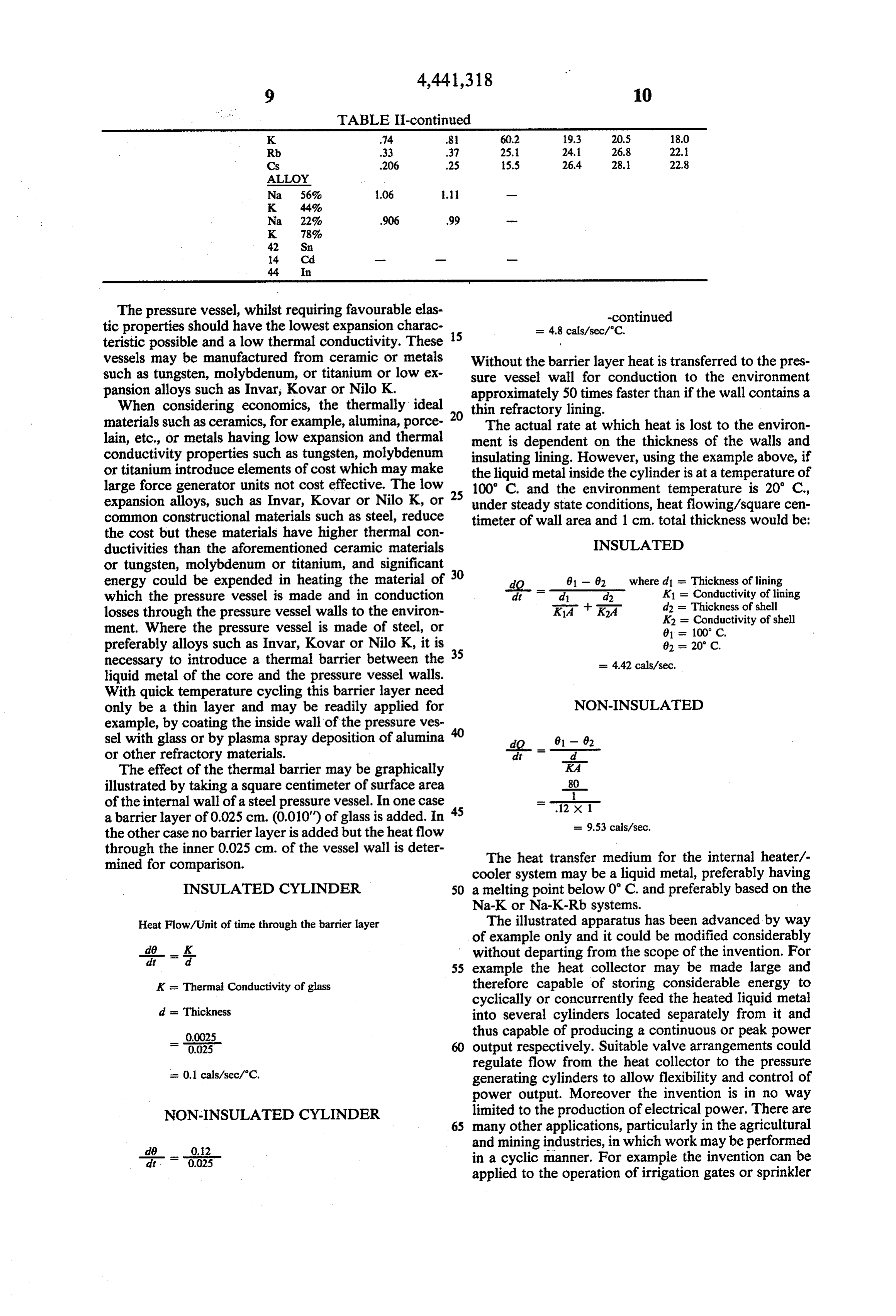
TABLE II-continued
K .74 81 60.2 19.3 20.5 18.0
Rb .33 37 25.1 24.1 26.8 22.
Cs .206 .25 15.5 26.4 28.1 22.8
ALLOY
The pressure vessel, whilst requiring favourable elas -continued tic properties should have the lowest expansion charac 15 = 4.8 calls/sec/C. teristic possible and a low thermal conductivity. These vessels may be manufactured from ceramic or metals Without the barrier layer heat is transferred to the pres such as tungsten, molybdenum, or titanium or low ex sure vessel wall for conduction to the environment pansion alloys such as Invar, Kovar or Nilo K. approximately 50 times faster than if the wall contains a When considering economics, the thermally ideal 20 thin refractory lining.
materials such as ceramics, for example, alumina, porce The actual rate at which heat is lost to the environ lain, etc., or metals having low expansion and thermal ment is dependent on the thickness of the walls and conductivity properties such as tungsten, molybdenum insulating lining. However, using the example above, if or titanium introduce elements of cost which may make the liquid metal inside the cylinder is at a temperature of large force generator units not cost effective. The low 100° C. and the environment temperature is 20' C., expansion alloys, such as Invar, Kovar or Nilo K, or 25 under steady state conditions, heat flowing/square cen common constructional materials such as steel, reduce timeter of wall area and 1 cm. total thickness would be: the cost but these materials have higher thermal con INSULATED ductivities than the aforementioned ceramic materials or tungsten, molybdenum or titanium, and significant energy could be expended in heating the material of 0 dO
81 - 02 where d1 = Thickness of lining d2 K1 = Conductivity of lining which the pressure vessel is made and in conduction losses through the pressure vessel walls to the environ K1A -
ment. Where the pressure vessel is made of steel, or 61 = 100 C. preferably alloys such as Invar, Kovar or Nilo K, it is 02 = 20° C. necessary to introduce a thermal barrier between the = 4.42 cals/sec. liquid metal of the core and the pressure vessel walls.
With quick temperature cycling this barrier layer need only be a thin layer and may be readily applied for NON-INSULATED example, by coating the inside wall of the pressure ves sel with glass or by plasma spray deposition of alumina doit - 9 -d 2 or other refractory materials.
The effect of the thermal barrier may be graphically KA illustrated by taking a square centimeter of surface area 80 of the internal wall of a steel pressure vessel. In one case 45 ---
a barrier layer of 0.025 cm. (0.010") of glass is added. In = 9.53 calls/sec. the other case no barrier layer is added but the heat flow through the inner 0.025 cm. of the vessel wall is deter The heat transfer medium for the internal heater/- mined for comparison. cooler system may be a liquid metal, preferably having INSULATED CYLINDER 50 a melting point below 0° C. and preferably based on the Na-K or Na-K-Rb systems.
Heat Flow/Unit of time through the barrier layer The illustrated apparatus has been advanced by way of example only and it could be modified considerably
without departing from the scope of the invention. For 55 example the heat collector may be made large and
K = Thermal Conductivity of glass therefore capable of storing considerable energy to cyclically or concurrently feed the heated liquid metal d = Thickness into several cylinders located separately from it and - 0.0025 thus capable of producing a continuous or peak power 0.025 60 output respectively. Suitable valve arrangements could regulate flow from the heat collector to the pressure = 0.1 calls/sec/C. generating cylinders to allow flexibility and control of power output. Moreover the invention is in no way
NON-INSULATED CYLINEDER 6S limited to the production of electrical power. There are many other applications, particularly in the agricultural
and mining industries, in which work may be performed at 0.025 in a cyclic manner. For example the invention can be applied to the operation of irrigation gates or sprinkler
Page 9
devices which need to be opened or turned on at sunrise sure within the vessel consequent on heating of said and closed or turned off at sunset or to the drying of body of metal or metal alloy. grain or minerals which might be exposed to sunlight 9. Apparatus as claimed in claim 8, including means for drying but protected during periods of rainfall. for applying heat to said body of metal or metal alloy. Moreover, the invention is not limited to the use of solar 10. Apparatus as claimed in claim 9, wherein said energy and may be applied to the retrieval of useful heat means includes means for collecting solar radiation and energy from other thermal equipment, such as from the applying heat energy from said radiation to said body of exhaust system of generators, boilers and turbines. metal or metal alloy.
Modifications and adaptations may be made to the 11. Apparatus as claimed in claim 8, including a plu above described without departing from the spirit and 10 rality of such devices and including means for combin scope of this invention which includes every novel ing the work output of said devices.
feature and combination of features disclosed herein. 12. A method of obtaining mechanical work from The claims form part of the disclosure of this specifi heat energy comprising: - cation. (a) confining within a pressure vessel a core material It is claimed: 15 of metal or metal alloy having a coefficient of vol 1. A method of obtaining mechanical work from heat ume expansion greater than said pressure vessel; energy comprising heating a body of liquid metal or (b) arranging movable member in communication liquid metal alloy confined within, but thermally insu with said core material for relative movement with lated from, a pressure vessel having a coefficient of 20 respect to said vessel;
volume expansion less than said body of metal or metal (c) thermally insulating the core material from the alloy contained therein thereby to generate a volumet internal surfaces of said vessel; ric expansion of said body whereby to cause an increase (d) thermally insulating a heat reservoir from said in pressure within the vessel and causing the increased COre;
pressure to move a load thereby to do work. (e) pumping a heat transfer medium through said 2. A method as claimed in claim 1, wherein said metal 25 reservoir to receive heat by indirect exchange with or metal alloy has a coefficient of volume expansion said reservoir; - greater than 10x10-6 ml/ml/K. and a melting point (f) heating said core material by pumping the heated or melting range such that the liquidus temperature medium from the reservoir through the core mate does not exceed 939 K. rial for indirect heat exchange with the metal or 3. A method as claimed in claim 1, wherein said metal 30 metal alloy and thereby effecting volumetric ex or metal alloy has a coefficient of volume expansion pansion of the core material and increasing the within the range 6x10⁻⁵ and 60x10-5 ml/ml/K. and pressure within the vessel to move the movable a melting point or melting range such that the liquidus member relative to the pressure vessel. temperature does not exceed 550 K. and the solidus 35 reservoir13. The method according to claim 12 wherein the temperature is not less than 200 K. is in the form of a cylinder substantially cir 4. A method as claimed in claim 1, wherein said metal cumscribing the pressure vessel. or metal alloy has a thermal capacity falling within the metal or metal alloyaccording
comprising the core material is a range 0.12 Joules/g/K. to 2.0 Joules/g/K.
5. A method as claimed in claim 1, wherein said body 40 liquid metal or liquid metal alloy and the heat exchange of metal or metal alloy is selected from the group con through aiscircuit medium a liquid metal or liquid metal alloy pumped connecting the reservoir with the core sisting of Group IA metals, magnesium, zinc, calcium, material. - aluminum, manganese, strontium, cadmium, indium, tin, 15. A method of obtaining mechanical work from mercury, barium and lead or combinations thereof. heat energy comprising:
6. A method as claimed in claim 1, wherein said pres 45 (a) confining within a pressure vessel a core material sure vessel comprises a material of low thermal expan of metal or metal alloy having a coefficient of vol sion and low thermal conductivity selected from the ume expansion greater than that of said pressure group consisting of ceramic material, metals selected vessel;
from the group consisting of tungsten, molybdenum, titanium, and metal alloys selected from the group con 50 (b)with arranging a movable member in communication said core material for relative movement with sisting of Invar, Kovar, and Nilo K, said metal alloys respect to said vessel; being coated with a thermally insulating layer. (c) thermally insulating the core material from the 7. A method as claimed in claim 1, including so heat internal surfaces of said vessel; ing said body of metal or metal alloy during spaced time (d) pumping a liquid metal or liquid metal alloy heat intervals and cooling or allowing said body of metal to 55 transfer medium through a reservoir to receive cool during the intervening time intervals so as to cycli heat by indirect exchange with said reservoir; cally produce work and further comprising heating at (e) heating said core material by pumping the heated least one other such body of metal or metal in a respec liquid from the reservoir through the core material tive number of such pressure vessels and combining the for indirect heat exchange with the metal or metal work outputs thereof. alloy and thereby effecting volumetric expansion 8. Apparatus for deriving mechanical work from heat of the core material and increasing the pressure energy comprising a device comprising a body of metal within the vessel to move the movable member or metal alloy, a pressure vessel confining but thermally relative to the pressure vessel. insulated from said body of metal or metal alloy, the 16. A method of obtaining mechanical work from pressure vessel having a co-efficient of volume expan 65 heat energy comprising:
sion less than that of said body of metal or metal alloy (a) confining within a pressure vessel a core material confined therein, and means adapted in use of the appa of metal or metal alloy having a coefficient of vol ratus to move a load in response to an increase in pres ume expansion greater than that of said pressure
Page 10
vessel, the metal or metal alloy comprising the core (e) pumping a liquid metal or liquid metal alloy heat transfer medium through said reservoir to receive material being a liquid metal or liquid metal alloy; heat by indirect exchange with said reservoir; (b) arranging a movable member in communication (f) heating said core material by pumping the liquid with said core material for relative movement with 5 metal or liquid metal alloy heat transfer medium through a circuit connecting the reservoir with the respect to said vessel; core material for indirect heat exchange with the (c) thermally insulating the core material from the metal or metal alloy and thereby effecting volumet internal surfaces of said vessel; ric expansion of the core material and increasing 10 the pressure within the vessel to move the movable (d) providing a heat reservoir thermally insulated member relativek to kthek pressure vessel.
from said core material;
Provenance
- Collection
- Cited prior art
- Original PDF
- patentimages.storage.googleapis.com →
- Filed
- 1982-06-16
- Pages
- 10
- Method
- pdftotext (the PDF's own text layer) + pdftoppm 300dpi page scans
- Source
- Google Patents bibliographic record
- Granted
- 1984-04-10
- Inventors
- Alexander Theckston
- Transcribed from
- patentimages.storage.googleapis.com →