patent · US4471738
Method and apparatus for minimizing the fuel usage in an internal combustion engine
18 September 1984
Page 1 — bibliographic record
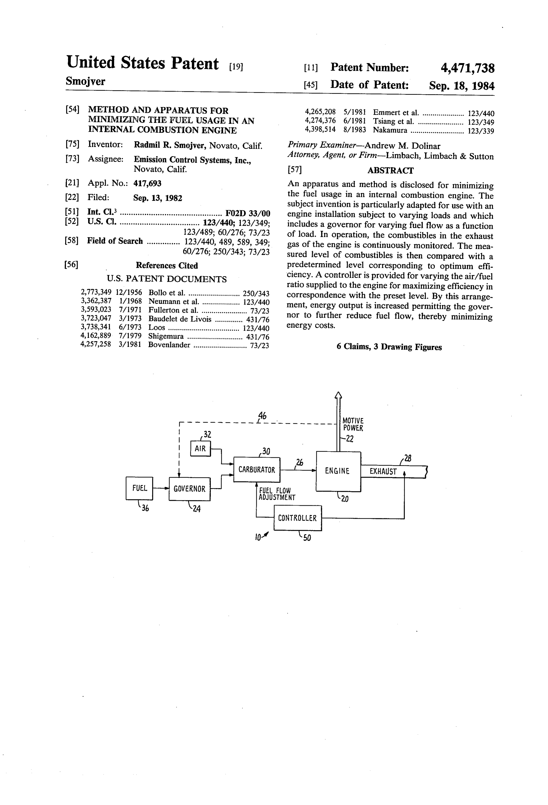
United States Patent (19) 11 Patent Number: 4,471,738 Smojver 45 Date of Patent: Sep. 18, 1984 (54) METHOD AND APPARATUS FOR 4,265,208 5/1981 Emmert et al. ..................... 123/440 MINIMIZING THE FUEL USAGE IN AN 4,274,376 6/1981 Tsiang et al. ....... ... 123/349 INTERNAL COMBUSTON ENGINE 4,398,514 8/1983 Nakamura ........................... 123/339 (75) Inventor: Radmil R. Smojver, Novato, Calif. Primary Examiner-Andrew M. Dolinar 73) Assignee: Emission Control Systems, Inc., Attorney, Agent, or Firm-Limbach, Limbach & Sutton Novato, Calif. 57 ABSTRACT (21) Appl. No.: 417,693 An apparatus and method is disclosed for minimizing 22 Filed: Sep. 13, 1982 the fuel usage in an internal combustion engine. The subject invention is particularly adapted for use with an 51) Int. Cl. .............................................. F02D 33/00 engine installation subject to varying loads and which 52 U.S. Cl. .................................... 123/440; 123/349; includes a governor for varying fuel flow as a function 123/489; 60/276; 73/23 of load. In operation, the combustibles in the exhaust 58) Field of Search ............... 123/440, 489, 589,349; gas of the engine is continuously monitored. The mea 60/276; 250/343; 73/23 sured level of combustibles is then compared with a 56) References Cited predetermined level corresponding to optimum effi
ratio supplied to the engine for maximizing efficiency in 2,773,349 12/1956 Bollo et al. .......................... 250/343 correspondence with the preset level. By this arrange 3,362,387 1/1968 Neumann et al. ..... ... 123/440 ment, energy output is increased permitting the gover 3,593,023 7/1971 Fullerton et al. ....................... 73/23 3,723,047 3/1973 Baudelet de Livois ...... ... 431/76 nor to further reduce fuel flow, thereby minimizing 3,738,341 6/1973 Loos .......................... ... 123/440 energy costs.
4,162,889 7/1979 Shigemura ........ ... 431/76 4,257,258 3/1981 Bovenlander ........................... 73/23 6 Claims, 3 Drawing Figures
POWER
CARBURATOR
FUEL FLOW
ADJUSTMENT
Page 2
Drawing sheet — no readable text.
Page 3
Drawing sheet — no readable text.
Page 4
arrangements which are only capable of making gross
METHOD AND APPARATUS FOR MINIMIZING adjustments to the flow of fuel. THE FUEL USAGE IN AN INTERNAL The inability of the governor to provide accurate COMBUSTION ENGINE adjustments is one factor which, in combination, gives 5 rise to inefficient operation. Another factor contribut
The subject invention relates to an apparatus and ing to this problem is that the engine must never be method for minimizing the fuel usage in an internal supplied with less fuel than is necessary to support the combustion engine. The subject invention is particu load. More particularly, the engine will tend to stall if larly adapted for use in an engine installation subject to supplied with too little fuel, thereby interrupting opera varying loads. More specifically, in an engine system 10 tions.
having a governor for adjusting the fuel flow as a func closelyAccordingly, if the governor were calibrated to follow the load, its inherent inaccuracy would tion of load, the subject invention is intended to fine frequently result in the stalling of the engine. Thus, in tune the fuel supply to maximize efficiency. practice, the governor is typically calibrated to deliver
slightly more fuel than necessary to prevent stalling. As
There has always been considerable interest in devel wasted can be appreciated, the extra fuel supply represents oping methods and apparatus for maximizing the effi energy.
Another ciency of energy generating devices. Recently, with the devices relates shortcoming associated with the prior art escalating price of fuel, it has become apparent that More particularly, to the adjustment of the air/fuel ratio. improvements in efficiency can translate into large cost mance of an engine,inallorder
adjustments, including the air/fsavings.
Examples of recently developed devices for enhanc uel ratio, are made based on the full load condition. The air/fuel ratio is typically adjusted through a carburetor ing the efficiency of energy generating devices can be system wherein fuel flow from the governor is supplied found in Baudelet De Livois U.S. Pat. No. 3,723,047, issued Mar. 27, 1973; and Shigemura U.S. Pat. No. 25 to a carburetor which mixes in air to permit combus 4,162,889, issued July 31, 1979. Both of these patents tion.
disclose feedback systems for use with furnaces. More theInload, operation, when the governor senses a reduction in particularly, in a prior art feedback system, combusti carburetor.it Since functions to reduce the fuel flow to the the air/fuel ratio at the carbureator bles in the exhaust line are monitored to determine the efficiency of the engine. If the engine is not burning at 30 has been adjusted based on maximum fuel flow, the maximum efficiency, the air flow to the furnace is ad resulting mixture associated with the reduced fuel flow condition will not achieve maximum combustion effi justed. By adjusting the air flow, efficient burning can ciency.
be achieved based on a given flow rate of fuel.
Both the above-cited prior art systems are particu Accordingly, it would be desirable to provide a larly adapted for use with furnace installations where 35 method for optimizing the efficiency of an internal com heat is produced to generate steam. Typically, furnace bustion engine. Unfortunately, the devices found in the installations are operated at maximum power at all prior art, designed for furnace control, are not suitable times. Thus, the fuel input rate is held relatively con for this purpose. More particularly, the prior art devices stant, while the air input is adjusted to insure efficient are designed merely to regulate air flow to a furnace burning. The previously cited patent to Shigemura pro which is being supplied with a relatively constant fuel vides a detailed explanation of the theories of efficient flow. In contrast, the subject invention is intended to combustion and is incorporated herein by reference. minimize fuel usage in an internal combustion engine A furnace installation is typically designed to operate subject to varying loads.
most efficiently at full power. The steam output from Accordingly, it is an object of the subject invention to the furnace is used to operate various types of machin 45 provide a new and improved apparatus and method for ery. In addition, the steam output can be used to drive minimizing the fuel usage, in an internal combustion turbines for the generation of electricity. In operation, engine system, which is subject to varying load condi when demand from the machinery drops, the excess tions.
steam is simply gated to the turbines to generate elec It is a further object of the subject invention to pro tricity. Thus, the system can be operated at full power 50 vide a new and improved apparatus for minimizing fuel at all times with no waste of generated steam. usage in an engine system which includes a governor A different situation exists in an installation utilizing for adjusting the rate of flow of fuel as a function of an internal combustion engine because there is no easy load.
means for utilizing its excess power capacity. In a typi It is another object of the subject invention to provide cal situation, such as a refinery setting, an internal com 55 a new and improved apparatus which continuously bustion engine is arranged to power a set of machines monitors the combustibles in the exhaust output of an which are cycled on and off during the work day. Since internal combustion engine to premit the fine tuning of the engine is called upon to deliver a wide range of the fuel supply for maximizing efficiency. power outputs based on the varying loads, it would be It is still a further object of the subject invention to extremely inefficient to run an internal combustion en 60 provide a new and improved method for continuously gine at full power during times of reduced load. monitoring the combustibles in the exhaust output of an Accordingly, in most known internal combustion internal combustion engine, which functions in combi engine installations, a means is provided for sensing the nation with a governor to fine tune the fuel supply for load on the engine and regulating the fuel flow as a maximizing efficiency.
function thereof. This means is generally referred to as 65 It is still another object of the subject invention to a governor and controls the flow of fuel in response to provide an apparatus and method which also improves the load on the engine. Unfortunately, the governors air quality of the exhaust of an engine and reduces main found in the prior art consist of relatively crude linkage tenance problems.
Page 5
SUMMARY OF THE INVENTION uel imixture is supplied to the engine by a carburetor 30. Carburetor 30 functions to mix air from supply 32 and
In accordance with these and many other objects, the fuel received from governor 24. Governor 24 controls subject invention is defined by a continuous feedback the flow of fuel between fuel, supply 36 and the carbu apparatus intended to work in conjunction with an retor 30.
internal combustion engine having a governor adapted As discussed above, when the engine is initially to adjust the fuel supply as a function of load. More tuned, the system is adjusted for peak power. Thus, particularly, a governor is provided which senses the maximum fuel flow is supplied to the engine in an at demand on the engine and restricts the flow of fuel in tempt to generate maximum power output. Carburetor rough correspondence to the requirements of the en 10 30 is then adjusted such that air flow provides enough gine. When the fuel supply is reduced, the operating oxygen to create the desired combustion efficiency. efficiency of the engine will drop because the air/fuel As discussed in the earlier cited patent to Shigemura, ratio has not been adjusted to compensate for the fuel maximum efficiency can be obtained by providing an air restriction. The latter condition is obviated by the sub supply that includes a limited amount of oxygen in ex ject invention. 15 cess of the theoretical amount of oxygen required for The intended result is achieved by monitoring the complete combustion. In practice, even this level of level of combustibles in the exhaust output of the en oxygen will not produce complete combustion such gine. The combustible level is compared with a prede that some level of particulates, on the order of a few termined value corresponding to maximum efficiency. parts per million, will be expelled into exhaust 28. As Based on the comparison, the actual fuel flow to the 20 pointed out in the Shigemura reference, it is undesirable engine is adjusted in order to maximize power output. to provide enough air to insure complete combustion, In the continuous system of the subject invention, when because a significant amount of wasted energy would be the fuel flow is fine tuned, engine efficiency will in expended to heat the nonoxygen components of the air. crease, enabling the governor to further reduce the flow Accordingly, in the desirable efficiency range, a mea of fuel, such that total fuel flow to the engine for a given 25 surable amount of particulates will always be present in load is minimized. the exhaust. It is these particulates which can be mea In the preferred embodiment of the subject invention, sured in order to operate the feedback system of the the monitor is defined by an infrared, carbon monoxide subject invention.
analyzer which is particularly sensitive to inefficient The quantative level of particulates in the exhaust fuel combustion. In operation, a sample from the ex 30 that would correspond to optimum performance will, of haust of the engine is supplied to the carbon monoxide course, vary from engine to engine. For example, cer analyzer. Prior to its entry into the analyzer, the sample tain engines are found to run better in either lean or rich is conditioned to remove any particulates and moisture burning environments. In any event, the optimum oper which would interfere with the analysis. ating condition of a particular engine can nevertheless Further objects and advantages of the subject inven 35 be correlated to a specific particulate output level. This tion will become apparent from the following detailed predetermined particulate output level can be calcu description taken in conjunction with the drawings in lated and utilized as a norm for maintaining the opti which: mum setting of the engine. Accordingly, it is to be un BRIEF DESCRIPTION OF THE DRAWINGS derstood that the subject invention is intended to in clude normalization around a predetermined level
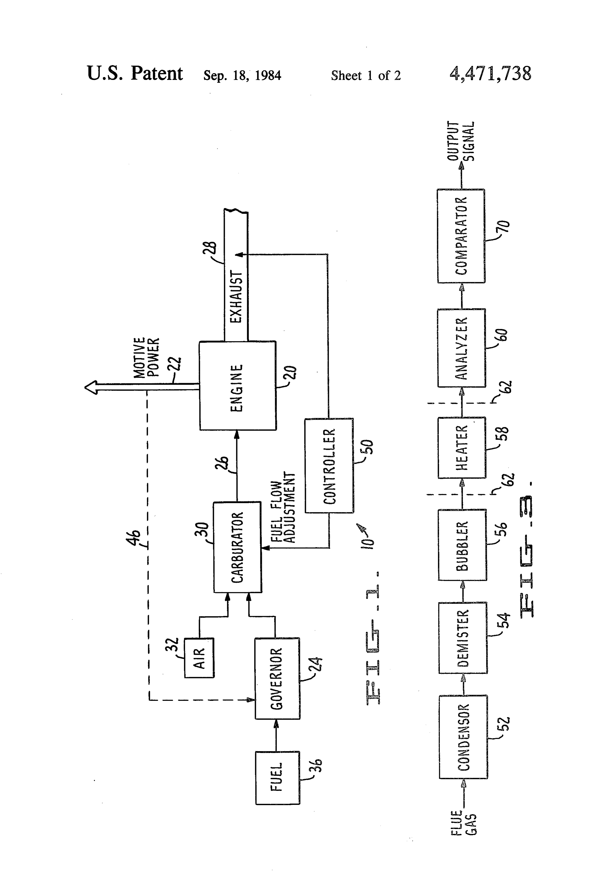
FIG. 1 is a block diagram illustrating the feedback which is suitable to the particular engine installation system of the subject invention. selected.
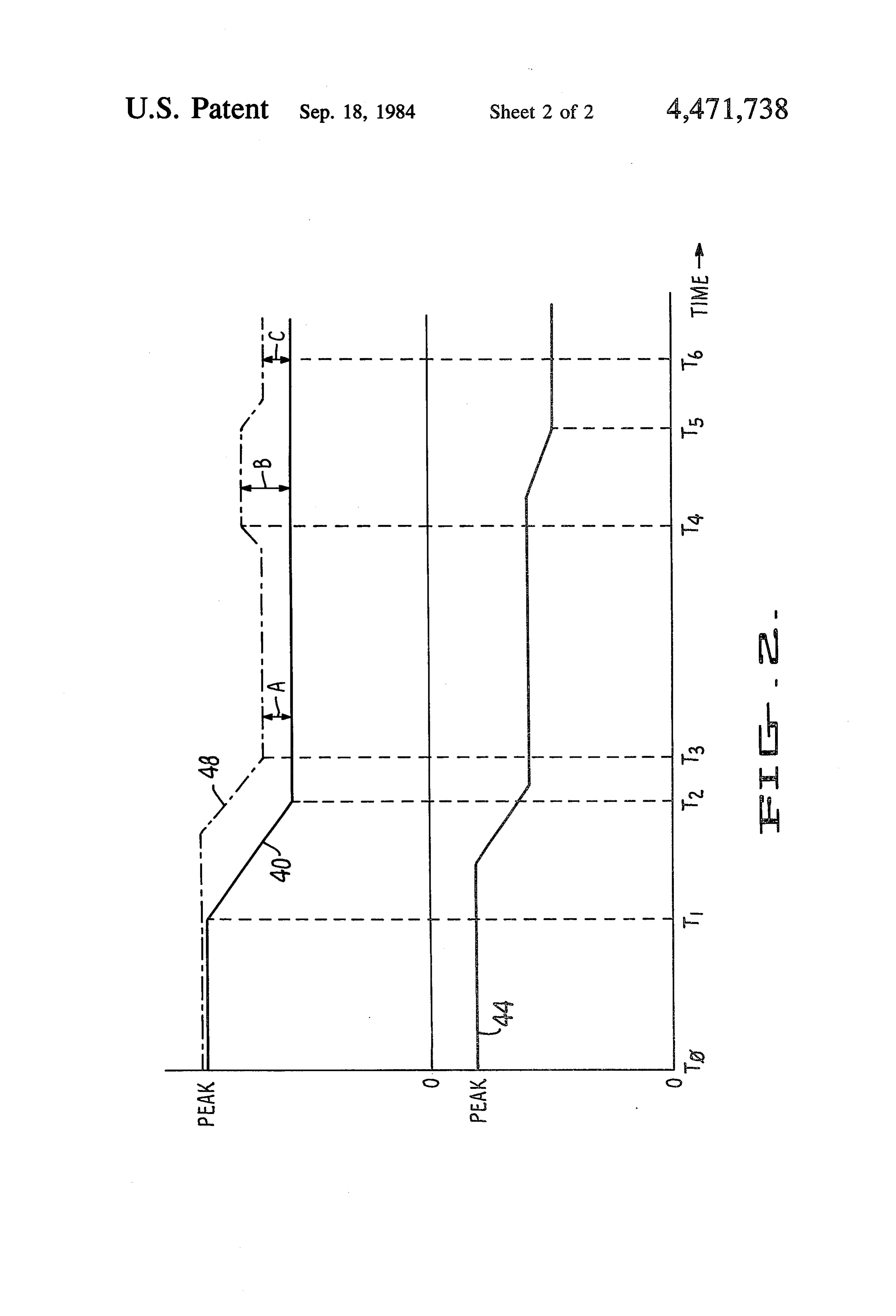
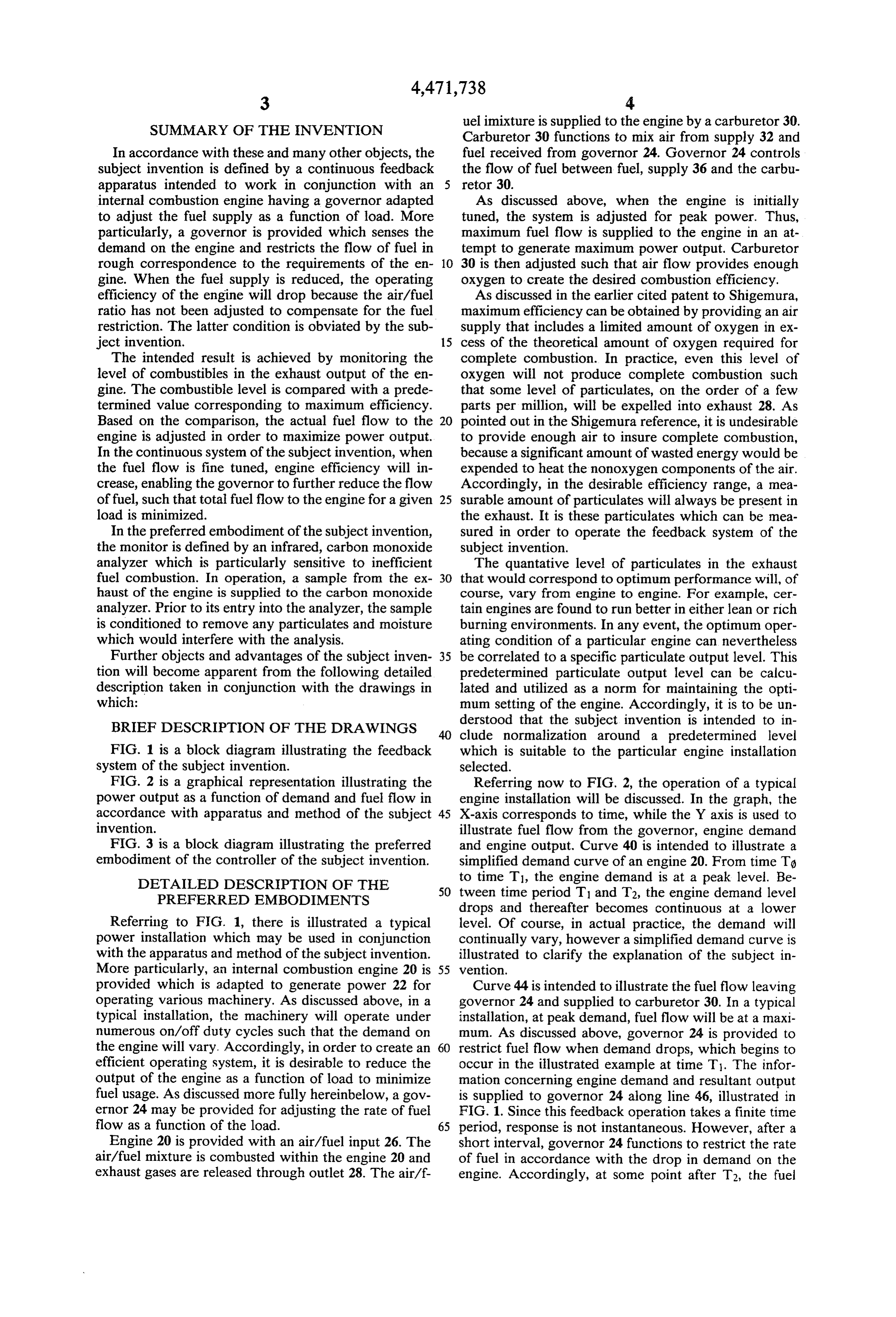
FIG. 2 is a graphical representation illustrating the Referring now to FIG. 2, the operation of a typical power output as a function of demand and fuel flow in engine installation will be discussed. In the graph, the accordance with apparatus and method of the subject 45 X-axis corresponds to time, while the Y axis is used to invention. illustrate fuel flow from the governor, engine demand FIG. 3 is a block diagram illustrating the preferred and engine output. Curve 40 is intended to illustrate a embodiment of the controller of the subject invention. simplified demand curve of an engine 20. From time To DETAILED DESCRIPTION OF THE to time T1, the engine demand is at a peak level. Be 50 tween time period T1 and T2, the engine demand level
PREFERRED EMBODIMENTS
drops and thereafter becomes continuous at a lower
Referring to FIG. 1, there is illustrated a typical level. Of course, in actual practice, the demand will power installation which may be used in conjunction continually vary, however a simplified demand curve is with the apparatus and method of the subject invention. illustrated to clarify the explanation of the subject in More particularly, an internal combustion engine 20 is 55 vention.
provided which is adapted to generate power 22 for Curve 44 is intended to illustrate the fuel flow leaving operating various machinery. As discussed above, in a governor 24 and supplied to carburetor 30. In a typical typical installation, the machinery will operate under installation, at peak demand, fuel flow will be at a maxi numerous on/off duty cycles such that the demand on mum. As discussed above, governor 24 is provided to the engine will vary. Accordingly, in order to create an restrict fuel flow when demand drops, which begins to efficient operating system, it is desirable to reduce the occur in the illustrated example at time T1. The infor output of the engine as a function of load to minimize mation concerning engine demand and resultant output fuel usage. As discussed more fully hereinbelow, a gov is supplied to governor 24 along line 46, illustrated in ernor 24 may be provided for adjusting the rate of fuel FIG. 1. Since this feedback operation takes a finite time flow as a function of the load. 65 period, response is not instantaneous. However, after a Engine 20 is provided with an air/fuel input 26. The short interval, governor 24 functions to restrict the rate air/fuel mixture is combusted within the engine 20 and of fuel in accordance with the drop in demand on the exhaust gases are released through outlet 28. The air/f- engine. Accordingly, at some point after T2, the fuel
Page 6
flow to the engine has been reduced a significant Referring now to FIG. 3, the preferred embodiment amount.
of the controller 50 will now be discussed. More partic
The effect of the reduction in fuel flow can be seen by ularly, it is intended that a small sample of the flue gas observing curve 48 which illustrates the energy output expelled through exhaust 28 of the engine be continu available from engine 20. Initially, engine output is at a ously withdrawn and supplied to an analyzer. In a typi peak level. However, as the fuel flow is reduced by cal installation, the exhaust gas from an engine is re governor 24, engine output is also reduced. It will be leased at an elevated temperature, on the order of 800' seen that immediately after point T3, a gap A, corre F. When the sample is removed from the flue, for exam sponding to excess power, exists between the output ple, via a pipe system, it is exposed to much cooler and demand curves. This relationship is unavoidable 10 outside temperatures, causing water in the sample to due to the inherent inaccuracies of the governor. As condense. Engine exhaust gas will typically have discussed above, the fuel supply must never be re 12-14% water content. In most known analyzers, con stricted an amount which would bring the demand densed water present in a sample would seriously inhibit above the output. The latter situation would result in a 15 the measurement of particulates. In the preferred em stall, interrupting operations and necessitating the re bodiment, which relies on the measurement of carbon starting of the engine. Thus, a governor is calibrated to monoxide particles, condensed water must be elimi insure that the output never drops below the demand. nated from the sample prior to measurement, to obtain Accordingly, in known prior art systems, the rate of accurate results. - fuel would reach a steady state at a level associated with In order to insure that water is removed, the sample point T3. As discussed more fully hereinbelow, by uti- 20 is first passed through a condenser 52 which operates to lizing the apparatus and method of the subject inven further reduce the temperature of the exhaust flow to tion, fuel flow can be further restricted, thereby saving 35 to 40' F. By further reducing the temperature of the energy costs. gas, a large percentage of the water in the sample will Referring again to FIG. 1, it will be seen that the 25 be condensed. The sample is then passed through a subject invention includes a controller 50 which is in demister 54 for removing the liquified water generated tended to fine tune the fuel supply to the engine. Con by the condenser. The demister can be in the form of a troller 50 operates by monitoring the particulates in the spinner which utilizes centrifugal force to remove exhaust 28 of the engine. The level of particulates are water The from the sample.
sample is then passed through a bubbler device compared to a predetermined value representing the desired operating range of the engine. The controller 30 56. In a bubbler, a gaseous sample is caused to percolate or bubble up through a liquid medium which results in then functions to fine tune the fuel flow at the carbure tor such that the particulate level of the exhaust will be additional embodiment, moisture being removed. In the preferred the sample can be further conditioned by driven to a level corresponding to the preset level. It is passing it through a heater 58 which insures that any intended that the controller function as a continuous 35 small amounts of remaining feedback arrangement such that fuel flow is continu gaseous phase prior to its entry water are driven back to the ously minimized. into analyzer 60. A pair Referring again to FIG. 2, the effect of providing a of filters 62 may be interposed on either side of heater controller 50 in conjunction with a prior art engine 58, to remove any unwanted particles unrelated to the installation is illustrated. As discussed above, when carbon monoxide particles of interest. In the preferred embodiment, by the time the sample reaches the analy demand, illustrated by curve 40, drops, the fuel flow zer, it will have a moisture content of less than 1%. from governor 24 is reduced thereby reducing the out put from engine 20. At this point, the air/fuel ratio is vention may be anabove,
As mentioned the analyzer of the subject in infrared detector capable of detect less than optimum. More particularly, and as pointed ing carbon monoxide particulates out above, carburetor 30 is typically adjusted to provide 45 output of the analyzer can be aninelectrical the sample. The voltage a particular ratio based on peak engine performance and which varies as a function of the particulates detected. maximum fuel flow. This ratio will not be the same for An infrared analyzer suitable for use in the subject in the reduced flow which occurs during reduced demand vention is manufactured by the Horiba Company. The periods. Accordingly, a measurable variation will occur Horiba analyzer can detect up to 20,000 parts per mil in the particulate level in the exhaust. 50 lion of carbon monoxide. It will operate with an accu This variation is monitored by the controller. In re racy range of plus or minus 5%.
sponse to this variation, the controller will output a fuel The voltage output of analyzer 60 is gated to a com flow adjustment signal to the carburetor. The air/fuel parator 70. Comparator 70 is preset with a voltage level ratio adjustment will in turn result in an increase in the corresponding to the desired particulate level in the efficiency of the engine. This increase is observed at 55 exhaust output. Comparator 70 functions to compare point T4 where engine output is increased. At this point, the input voltage from analyzer 60 with the preset level the difference between the demand curve 40 and the to determine the variance from the optimum setting. output curve 48 or excess power is equal to a value B, Comparator 70 then operates to generate an output which is significantly greater than the separation A, signal for adjusting the fuel flow from carburetor 30. illustrated at point T3. This increase of excess power is 60 Comparator 70 may be defined by a microprocessor transmitted back to the governor 24, such that governor which is programmable with the predetermined set 24 may respond by further restricting the flow of fuel. point. One microprocessor suitable for use with the The drop in fuel is indicated at point Ts on curve 44. subject invention is a 560 Series Microprocessor Con This drop results in the restoration of the excess power troller manufactured by the Barber-Colman Company. gap to a level C, at point Té, which corresponds to the 65 The output from comparator 70 is supplied to carbu gap A at point T3. As can be appreciated, the fuel flow retor 30. Typically, the carburetor is adjusted by means after point T5 is at a minimum such that energy savings of a rotatable screw. Accordingly, an electrically con are maximized. trolled actuator may be mounted to the carburetor for

Page 7
producing the air/fuel ratio adjustments. Both electric including a governor means, said governor means for or pneumatic actuators can be used depending on the adjusting the flow of fuel to said engine as a function of particular application. A typical actuator suitable for load, said apparatus comprising:
use with the subject invention is the Model 659 Resis means for monitoring the combustibles in the exhaust tance to Position Converter manufactured by the Bar output, said monitoring means including a con ber-Colman Company. denser for condensing water contained in said ex In summary, there has been provided a new and im haust output, said monitoring means further includ proved apparatus and method for minimizing the fuel ing a demister connected in line with said con usage in an internal combustion engine. More particu denser for removing said condensed water, said larly, in an internal combustion engine, subject to vary 10 monitoring means also including a bubbler con ing loads, a governor 24 is provided for varying fuel nected in line with said demister for removing flow as a function of load. When the fuel flow is re additional moisture from said exhaust output; stricted as the result of a drop in demand, the air/fuel means for comparing the level of said combustibles to ratio must be readjusted to maximize efficiency. Ac a predetermined value; and cordingly, in the subject invention, the carbon monox 15 means for adjusting the rate of fuel from said gover ide in the exhaust 28 of an engine 20 is monitored. The nor to said engine in a manner such that the level of particulate level is then compared to a preset level cor combustibles equals said predetermined value, responding to optimum performance. A controller 50 whereby said apparatus functions to fine tune the then functions to readjust the air fuel ratio to improve fuel supply to said engine thereby maximizing effi the efficiency of the operation of the engine. By this 20 ciency.
arrangement, the governor is able to further reduce fuel 2. An apparatus as recited in claim 1 wherein said flow, thereby minimizing fuel usage. Other advantages monitoring means further includes a heater for raising gained by improving the quality of combustion, include the temperature of said exhaust for vaporizing any re the reduction of maintenance problems and air pollu tion. 25 maining water.
While the subject invention has been described with 3. An apparatus as recited in claim 2 further including relation to a preferred embodiment, it is to be under filter means interposed between said bubbler and heater stood that various other changes and modifications for removing any particulates from said exhaust. could be made therein by one skilled in the art, without 4. An apparatus as recited in claim 1 wherein said varying from the scope and spirit of the subject inven 30 monitoring means includes an infrared analyzer. tion as defined by the appended claims. 5. An apparatus as recited in claim 4 wherein said I claim: infrared analyzer measures carbon monoxide levels in 1. An apparatus for minimizing the fuel usage in an said exhaust.
internal combustion engine, wherein said engine is sub 6. An apparatus as recited in claim 1 wherein said ject to varying loads, said engine having a fuel input and 35 comparator means includes a microprocessor. an air input and an exhaust output, said engine further
Provenance
- Collection
- Cited prior art
- Original PDF
- patentimages.storage.googleapis.com →
- Filed
- 1982-09-13
- Pages
- 7
- Method
- pdftotext (the PDF's own text layer) + pdftoppm 300dpi page scans
- Source
- Google Patents bibliographic record
- Granted
- 1984-09-18
- Inventors
- Radmil R. Smojver; EMISSION CONTROL SYSTEMS Inc
- Transcribed from
- patentimages.storage.googleapis.com →