patent · US5832718
Combustion chamber especially for a gas turbine engine using hydrogen as fuel
10 November 1998
Page 1 — bibliographic record
United States Patent (19) 11 Patent Number: 5,832,718 Suttrop (45) Date of Patent: Nov. 10, 1998 54) COMBUSTION CHAMBER ESPECIALLY 3.237,400 3/1966 Kuhrt ........................................ 60/736
FOR A GAS TURBINE ENGINE USING
HYDROGENAS FUEL FOREIGN PATENT DOCUMENTS
75 Inventor: Friedemann Suttrop, Aachen, 1104211 11/1955 France ..................................... 60/736 Germany
73 ASSignee: tthenArtiseAirbus Primary Examiner Louis J. Casaregola s 9: y Attorney, Agent, or Firm W. F. Fasse; W. G. Fasse 21 Appl. No.: 770,725 57 ABSTRACT
O O A combustion chamber for a gas turbine using hydrogen as 30 Foreign Application Priority Data fuel, is equipped with an evaporator for liquid hydrogen Dec. 19, 1995 IDE Germany ........................ 19547515.1 which converts the hydrogen into its gaseous form that is fed 51) Int. Cl. ............................... E02C 3/22; E02C 7/224 directly or for instance via an external control valve into the 52 U.S. Cl. ............................................ 60/39.465; 60/736 combustor. The evaporator covers and protects at least a 58 Field of Search ................................. 60/39.465, 736, portion of the inner and/or outer wall that encloses the 60/737, 39.05, 39.52, 39.55, 267 combustion chamber, whereby the evaporator also cools the
combustion chamber while converting the liquid hydrogen to gaseous hydrogen.
2,221,477 12/1940 Powter et al. ............................ 60/737 13 Claims, 2 Drawing Sheets
Aziz l
AR NLET
COMBUSTOR E 3C
Page 2
Drawing sheet — no readable text.
Page 3
Drawing sheet — no readable text.
Page 4
COMBUSTION CHAMBER ESPECIALLY perative heat eXchange between the flame tube walls and the FOR A GAS TURBINE ENGINE USING evaporator. Simultaneously, the invention avoids the con HYDROGENAS FUEL ventional need for Separate cooling features for the com bustion chamber wall, Such as a film cooling or Veil or mist
FIELD OF THE INVENTION cooling by passing a coolant into contact with the combus tion chamber walls. Thus, the invention avoids or Substan
The invention relates generally to combustion chambers tially reduces the use of cooling air for the purpose of and particularly to Such chambers useful in gas turbine cooling the combustion chamber, whereby the Saved air engines using hydrogen as fuel. Such combustion chamber portion can be Supplied into the combustion chamber for generally includes a housing, a combustor or burner, and a Sustaining the combustion.
flame tube.
By integrating the evaporator with the combustion cham
BACKGROUND INFORMATION ber as taught herein, the formation of ice on the evaporator is more easily avoided than in conventional Structures due to
Combustion chambers of the type mentioned above com the high pressures and high temperatures in the combustion prise a gap between the housing and the flame tube for 15 chamber.
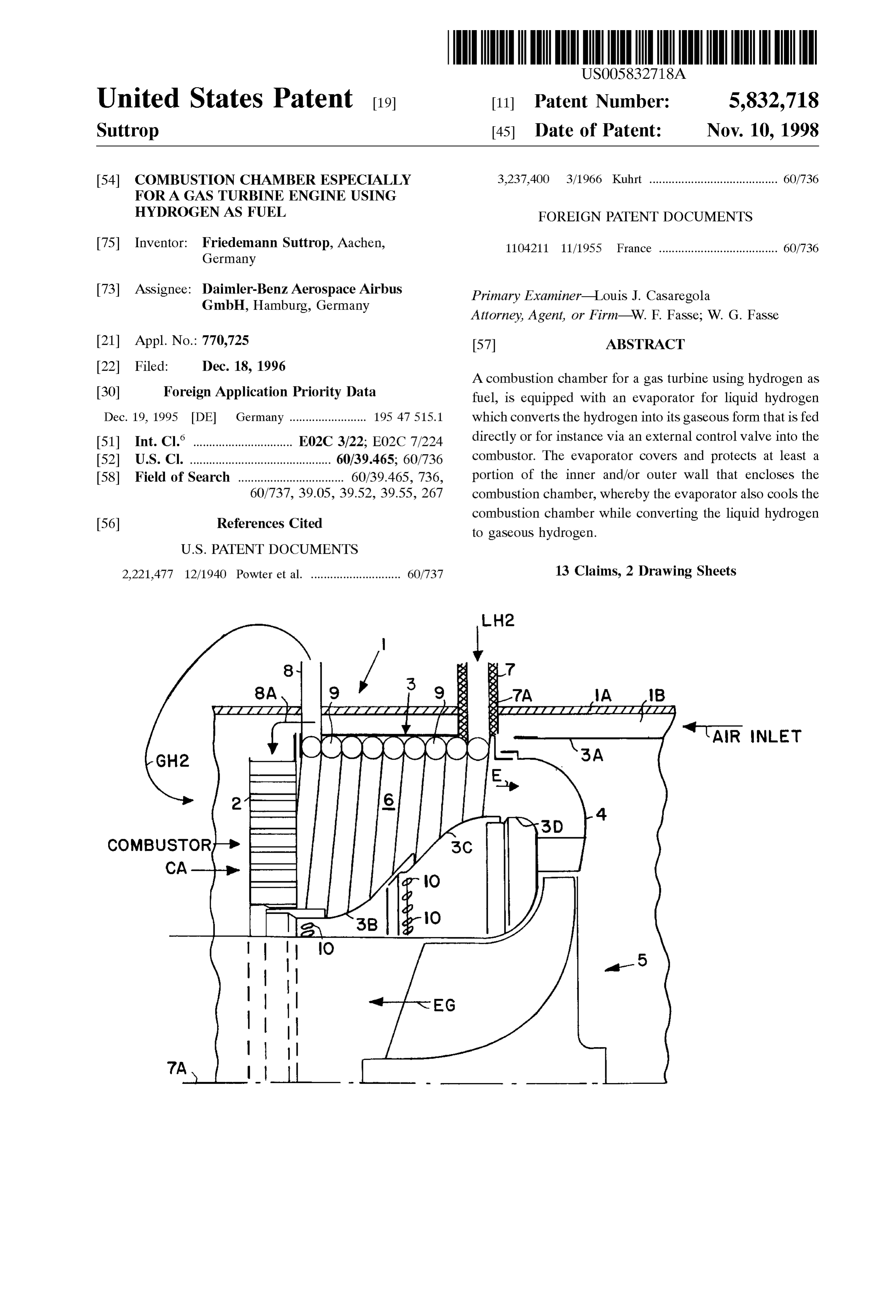
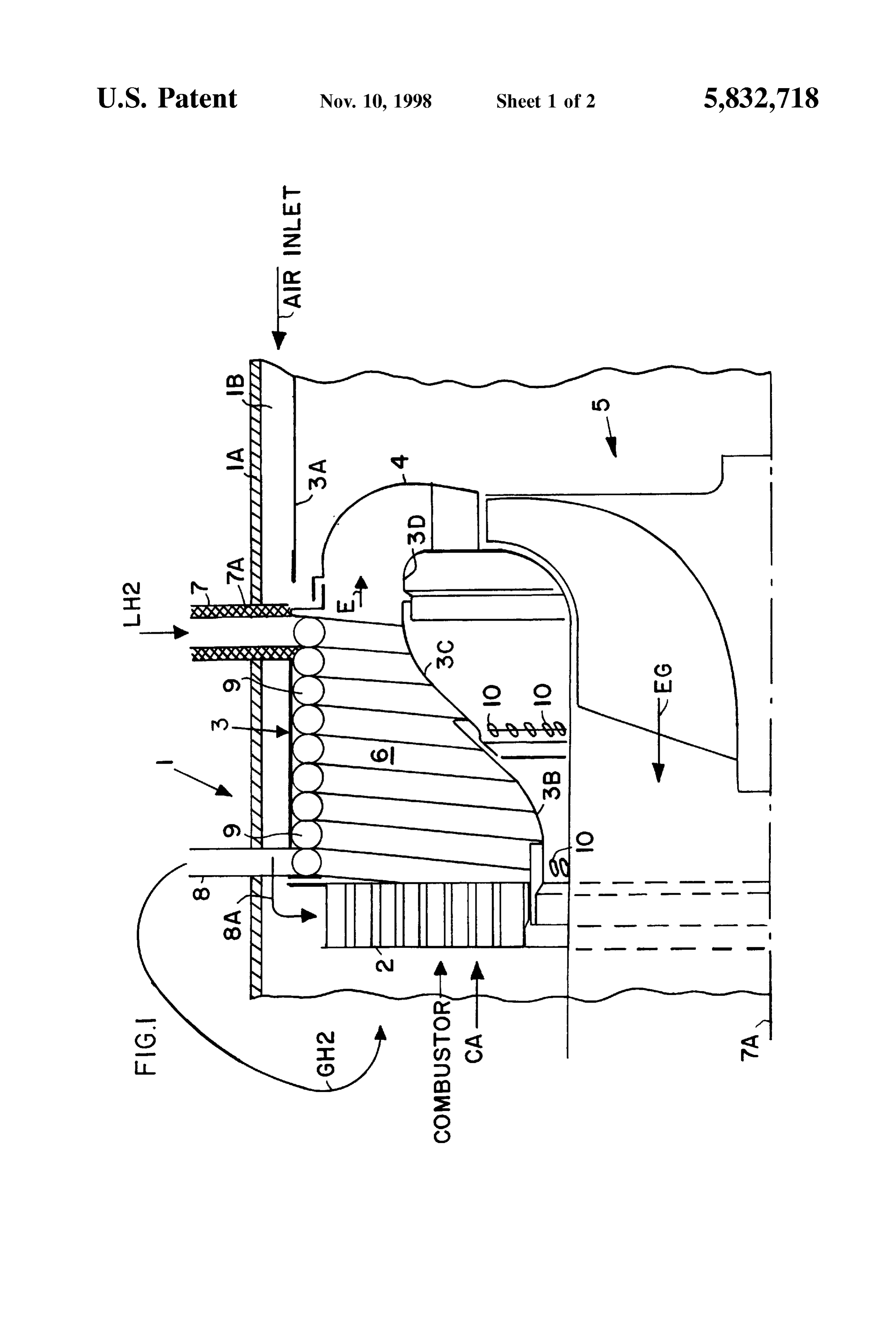
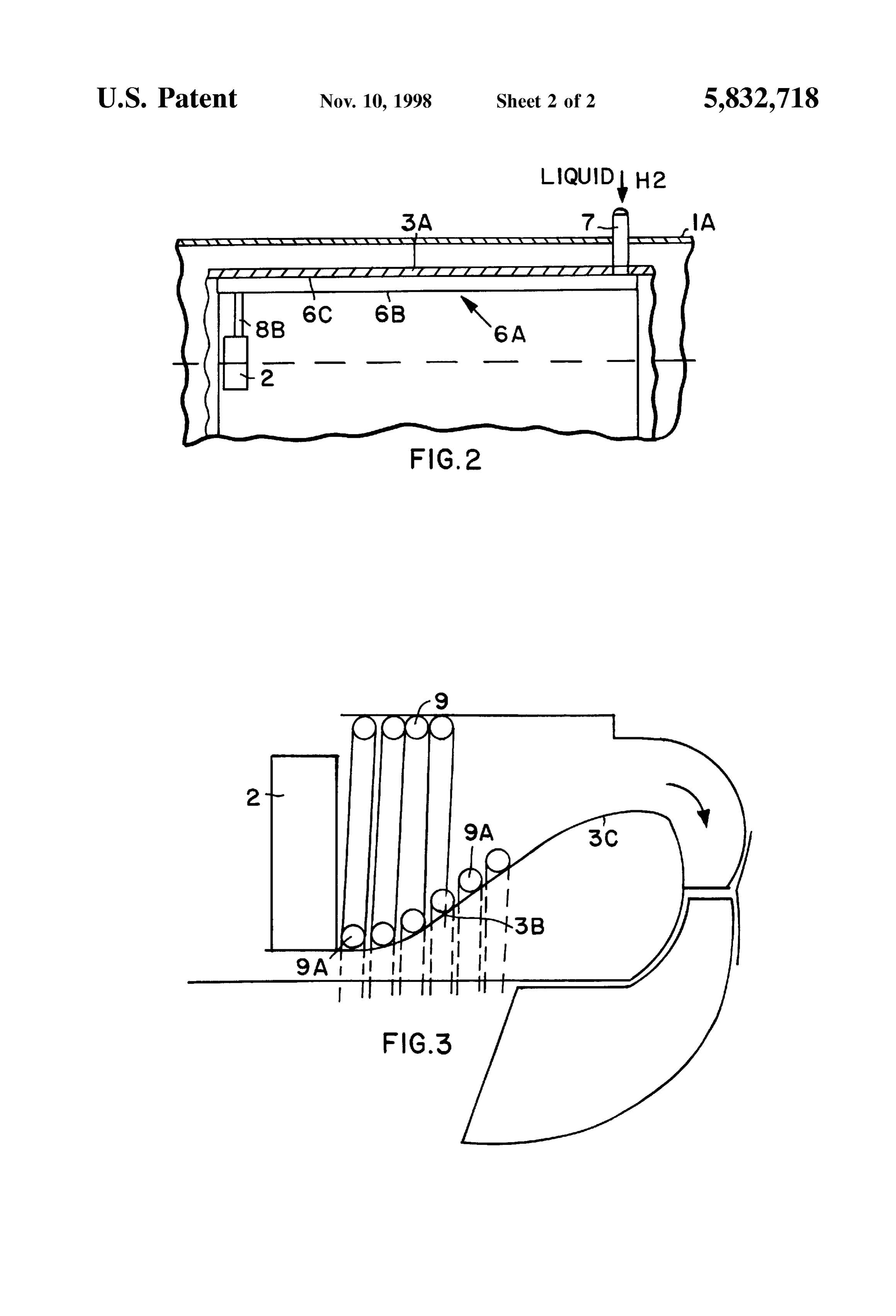
flowing cooling air through the gap which leads into a Further, the construction of the evaporator as a double cooling air guide channel around the flame tube. If the wall or as a helically wound pipe has the advantage that it hydrogen is Supplied to the combustion chamber of the gas is a simple construction which is economical to produce. turbine engine in the form of liquid hydrogen, but shall be combusted in its gaseous State, it is necessary to provide an BRIEF DESCRIPTION OF THE DRAWING evaporator for the liquid hydrogen. Various constructions and arrangement of Such evaporators are known in the art. In order that the invention may be clearly understood, it Thus, it is for example known to position the evaporator in will now be described, by way of example, with reference to the exhaust gas Stream of the turbine. According to another the accompanying drawings, wherein: conventional arrangement, the evaporator is positioned in 25 FIG. 1 shows a Schematic axial Sectional view through a the area of the compressor where it functions as an inter combustion chamber and evaporator according to the inven mediate cooler between two compressor Stages. Yet another tion shown as part of a radial turbine Stage; conventional construction positions the evaporator at the FIG. 2 shows schematically a combustion chamber wall entrance to the combustion chamber. This last mentioned in heat eXchange contact with a double-walled hydrogen position of the evaporator requires only short fluid ducts. evaporator; and
However, all the other conventional constructions require FIG. 3 shows a coiled hydrogen evaporator in heat fluid ducts of Substantial length between the evaporator and eXchange contact with a radially inner combustion chamber the combustion chamber. Such long ducts have an adverse Surface portion.
effect on the speed with which the turbine reacts to control measures. A disadvantage common to all conventional con 35 DETAILED DESCRIPTION OF PREFERRED Structions resides in the danger that ice may be formed on EXAMPLE EMBODIMENTS AND OF THE the evaporator. BEST MODE OF THE INVENTION OBJECTS OF THE INVENTION FIG. 1 shows a combustion chamber constructed, for 40 example, as a ring combustion chamber 1 having a housing
In view of the above it is the aim of the invention to 1A enclosing a combustor or burner 2 and a flame tube 3 achieve the following objects Singly or in combination: having a radially outer wall 3A and radially inner wall to construct a combustion chamber of the type described sections 3B, 3C, 3D enclosing a combustion chamber, the above in Such a way that it is integrated with an evaporator; front end of which is closed by the combustor 2. An air to efficiently cool the combustion chamber with the help 45 channel 1B surrounds the flame pipe wall 3A and feeds of the evaporator, and combustion air CA into the combustor 2. The combustion to avoid the drawbacks of conventional structures of this gases E flow through an exit 4 of the flame tube 3 into a type, especially ice formations are to be avoided. radial turbine 5. Exhaust gases leave the radial turbine 5 as indicated by the arrow EG. The air channel 1B, the flame
SUMMARY OF THE INVENTION 50 tube wall 3A, 3B, 3C, 3D, and the evaporator 6 form rings around a central turbine axis 7A.
According to the invention the above objects have been According to the invention an evaporator 6 is integrated achieved in a combustion chamber for operating a gas with and positioned in heat eXchange contact with a heat turbine with hydrogen as fuel, which is characterized in that tube wall Surface facing inwardly into the flame tube ring an evaporator having an inlet port for liquid hydrogen and an 55 outlet port for gaseous hydrogen is arranged inside the flame volume of the flame tube 3. In FIG. 1 the evaporator 6 contacts the inwardly facing Surface of the outer flame tube tube of the combustion chamber in such a position that the wall 3A. The evaporator 6 comprises a plurality of helically evaporator covers at least a portion of the inner Surface of wound tube windings 9 forming a coil. One end of the coil the flame tube. is connected through an inlet port 7 to a Source of liquid Preferably, the evaporator is constructed as a pipe heli 60 hydrogen LH2. The port 7 preferably has a heat insulated cally wound into a coil or it is constructed as a double wall inlet wall 7A. The other end of the helical coil is connected of the combustion chamber, whereby the exit port for the to an exit port 8 for discharging gaseous hydrogen GH2, gaseous hydrogen is directly connected with the combustor. preferably directly into the burner 2 through a short duct 8A. By integrating the evaporator with the wall of the flame The just described construction assures that the helical coil tube of the turbine combustion chamber, the invention 65 covers at least a portion of the inner Surface of the flame tube achieves the Special advantage that an efficient and effective 3. The individual turns of the coil of the evaporator 6 are cooling of the combustion chamber is provided by a recu positioned to receive heat for the evaporation from the
Page 5
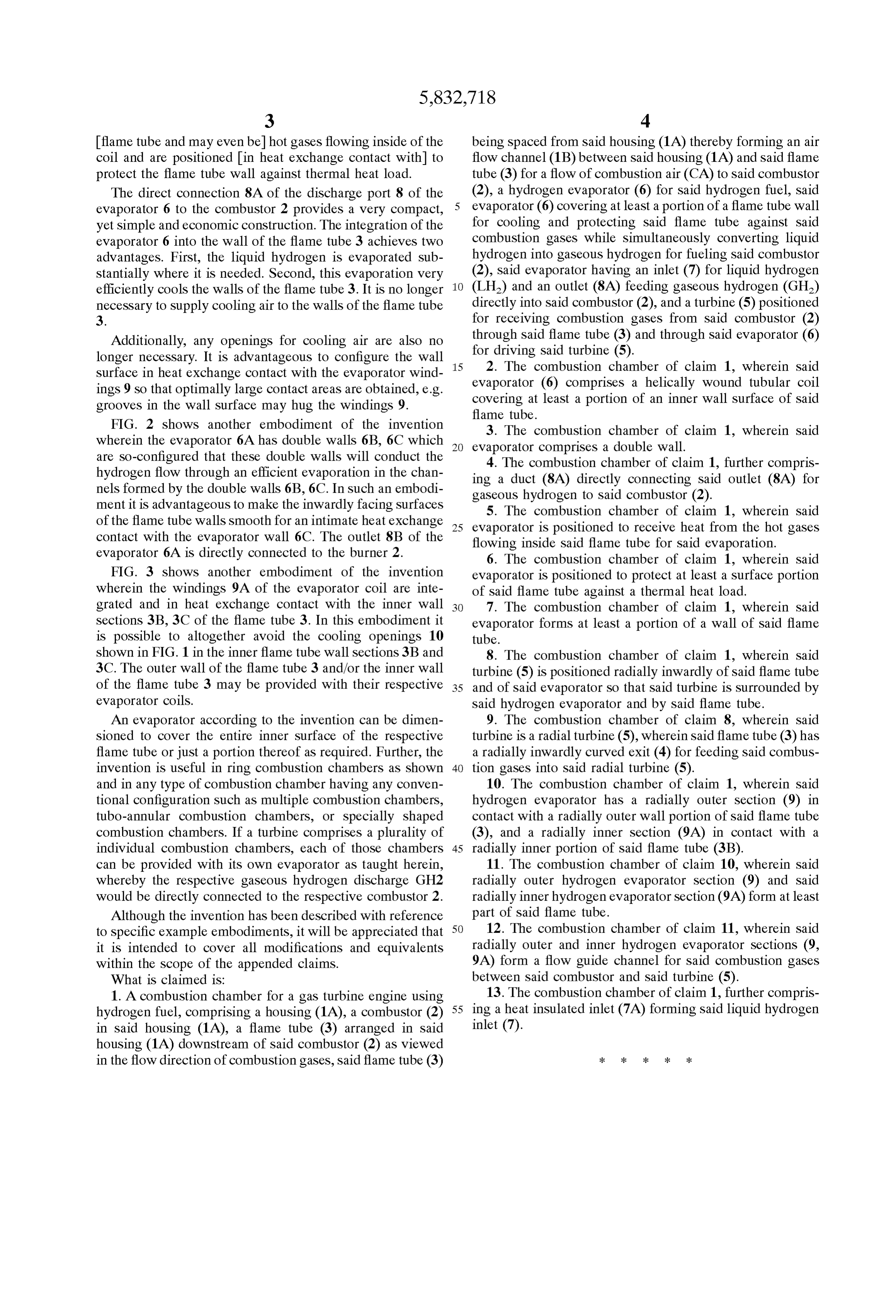
flame tube and may even be hot gases flowing inside of the being spaced from said housing (1A) thereby forming an air coil and are positioned in heat exchange contact with to flow channel (1B) between said housing (1A) and said flame protect the flame tube wall against thermal heat load. tube (3) for a flow of combustion air (CA) to said combustor The direct connection 8A of the discharge port 8 of the (2), a hydrogen evaporator (6) for said hydrogen fuel, Said evaporator 6 to the combustor 2 provides a very compact, evaporator (6) covering at least a portion of a flame tube wall yet simple and economic construction. The integration of the for cooling and protecting Said flame tube against Said evaporator 6 into the wall of the flame tube 3 achieves two combustion gases while Simultaneously converting liquid advantages. First, the liquid hydrogen is evaporated Sub hydrogen into gaseous hydrogen for fueling Said combustor Stantially where it is needed. Second, this evaporation very (2), Said evaporator having an inlet (7) for liquid hydrogen efficiently cools the walls of the flame tube 3. It is no longer(LH2) and an outlet (8A) feeding gaseous hydrogen (GH2) necessary to Supply cooling air to the walls of the flame tube directly into said combustor (2), and a turbine (5) positioned 3. for receiving combustion gases from Said combustor (2) Additionally, any openings for cooling air are also no through said flame tube (3) and through said evaporator (6) longer necessary. It is advantageous to configure the wall 15 for driving said turbine (5).
2. The combustion chamber of claim 1, wherein said
Surface in heat eXchange contact with the evaporator wind evaporator ingS 9 So that optimally large contact areas are obtained, e.g. (6) comprises a helically wound tubular coil grooves in the wall Surface may hug the windingS 9. covering at least a portion of an inner wall Surface of Said flame tube.
FIG. 2 shows another embodiment of the invention 3. The combustion chamber of claim 1, wherein said wherein the evaporator 6A has double walls 6B, 6C which evaporator comprises a double wall. are So-configured that these double walls will conduct the 4. The combustion chamber of claim 1, further compris hydrogen flow through an efficient evaporation in the chan ing a duct (8A) directly connecting said outlet (8A) for nels formed by the double walls 6B, 6C. In such an embodi gaseous hydrogen to said combustor (2). ment it is advantageous to make the inwardly facing Surfaces 5. The combustion chamber of claim 1, wherein said of the flame tube walls Smooth for an intimate heat eXchange 25 evaporator is positioned to receive heat from the hot gases contact with the evaporator wall 6C. The outlet 8B of the flowing inside Said flame tube for Said evaporation. evaporator 6A is directly connected to the burner 2. 6. The combustion chamber of claim 1, wherein said FIG. 3 shows another embodiment of the invention evaporator is positioned to protect at least a Surface portion wherein the windings 9A of the evaporator coil are inte of Said flame tube against a thermal heat load. grated and in heat eXchange contact with the inner wall 7. The combustion chamber of claim 1, wherein said Sections 3B, 3C of the flame tube 3. In this embodiment it evaporator forms at least a portion of a wall of Said flame is possible to altogether avoid the cooling openings 10 tube.
shown in FIG. 1 in the inner flame tube wall sections 3B and 8. The combustion chamber of claim 1, wherein Said 3C. The outer wall of the flame tube 3 and/or the inner wall turbine (5) is positioned radially inwardly of said flame tube of the flame tube 3 may be provided with their respective 35 and of Said evaporator So that Said turbine is Surrounded by evaporator coils. Said hydrogen evaporator and by Said flame tube. An evaporator according to the invention can be dimen 9. The combustion chamber of claim 8, wherein said Sioned to cover the entire inner Surface of the respective turbine is a radial turbine (5), wherein said flame tube (3) has flame tube or just a portion thereof as required. Further, the a radially inwardly curved exit (4) for feeding said combus invention is useful in ring combustion chambers as shown 40 tion gases into Said radial turbine (5). and in any type of combustion chamber having any conven 10. The combustion chamber of claim 1, wherein said tional configuration Such as multiple combustion chambers, hydrogen evaporator has a radially outer Section (9) in tubo-annular combustion chambers, or Specially shaped contact with a radially outer wall portion of said flame tube combustion chambers. If a turbine comprises a plurality of (3), and a radially inner section (9A) in contact with a individual combustion chambers, each of those chambers 45 radially inner portion of said flame tube (3B). can be provided with its own evaporator as taught herein, 11. The combustion chamber of claim 10, wherein said whereby the respective gaseous hydrogen discharge GH2 radially outer hydrogen evaporator Section (9) and Said would be directly connected to the respective combustor 2. radially inner hydrogen evaporator Section (9A) form at least Although the invention has been described with reference part of Said flame tube.
to specific example embodiments, it will be appreciated that 50 12. The combustion chamber of claim 11, wherein said it is intended to cover all modifications and equivalents radially outer and inner hydrogen evaporator Sections (9, within the Scope of the appended claims. 9A) form a flow guide channel for said combustion gases What is claimed is: between said combustor and said turbine (5). 1. A combustion chamber for a gas turbine engine using 13. The combustion chamber of claim 1, further compris hydrogen fuel, comprising a housing (1A), a combustor (2) 55 ing a heat insulated inlet (7A) forming said liquid hydrogen in Said housing (1A), a flame tube (3) arranged in Said inlet (7).
housing (1A) downstream of said combustor (2) as viewed in the flow direction of combustion gases, said flame tube (3)
Page 6
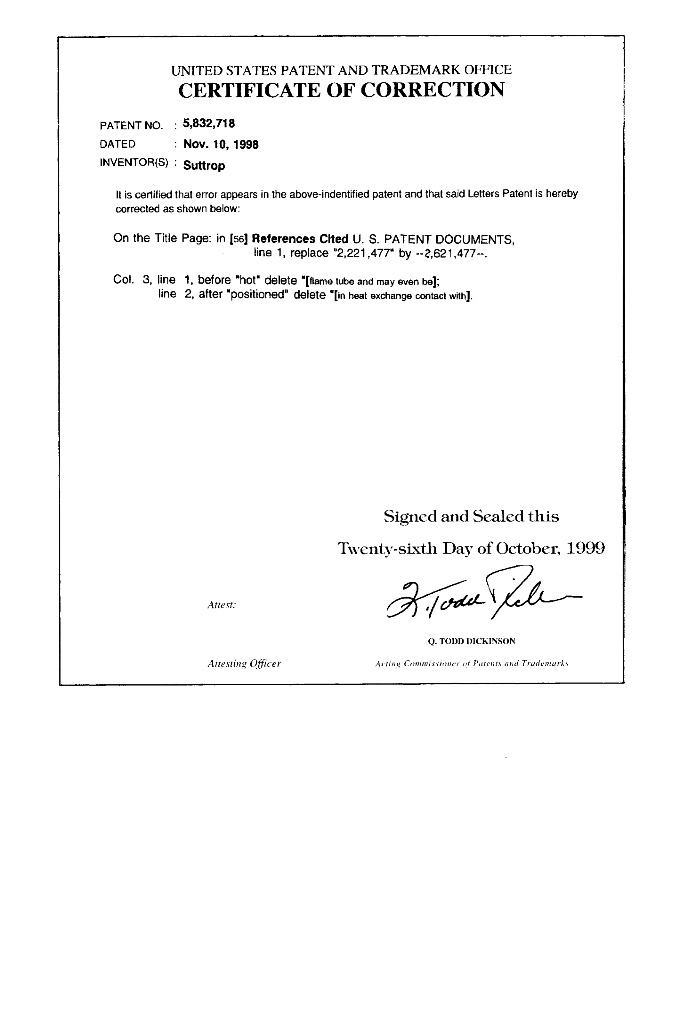
UNITED STATES PATENT AND TRADEMARK OFFICE
CERTIFICATE OF CORRECTION
it is certified that error appears in the above-indentified patent and that said Letters Patent is hereby Corrected as shown below:
On the Title Page: in 56) References Cited U. S. PATENT DOCUMENTS,
Col. 3, line 1, before "hot" delete "flame tube and may even bel; line 2, after "positioned" delete "in heat exchange contact with). Signed and Sealed this
Twenty-sixth Day of October, 1999
Q. TODD DICKINSON
Attesting Officer A tig Crn missioner (f. Pute its cinct Tracle nic ky
Provenance
- Collection
- Cited prior art
- Original PDF
- patentimages.storage.googleapis.com →
- Filed
- 1996-12-18
- Pages
- 6
- Method
- pdftotext (the PDF's own text layer) + pdftoppm 300dpi page scans
- Source
- Google Patents bibliographic record
- Granted
- 1998-11-10
- Inventors
- Friedemann Suttrop; Airbus Operations GmbH
- Transcribed from
- patentimages.storage.googleapis.com →