patent · US4393817
Combustion and pollution control system
19 July 1983
Page 1 — bibliographic record
United States Patent 19 11 4,393,817 Lindberg 45 Jul. 19, 1983 54 COMBUSTION AND POLLUTION 3,682,142 8/1972 Newkirk ................................. 123/3
CONTROL SYSTEM
FOREIGN PATENT DOCUMENTS
(75) Inventor: John E. Lindberg, Lafayette, Calif. 95568 1/1924 Austria ............................. 123/25 P (73) Assignee: Owen, Wickersham & Erickson, San OTHER PUBLICATIONS Francisco, Calif.
21) Appl. No.: 190,932 Automobile Engineer, Sep. 1944, pp. 372, 373, 374. 22 Fied: Sep. 25, 1980 Primary Examiner-Wendell E. Burns Attorney, Agent, or Firm-Owen, Wickersham &
Erickson
Related U.S. Application Data (60) Division of Ser. No. 657,747, Feb. 13, 1976, aban 57 ABSTRACT doned, which is a continuation-in-part of Ser. No. A controlled amount of a fluid (steam or water or a 613,867, Sep. 16, 1975, abandoned, which is a continua solution of water plus additives) is injected into an inter tion-in-part of Ser. No. 356,589, May 3, 1973, aban nal combustion engine to improve combustion, effi doned, which is a continuation-in-part of Ser. No. ciency, and to reduce emissions. The amount of the 227,440, Feb. 18, 1972, abandoned. fluid injected is controlled in response to engine need. 51 Int. Cl..................... FO2B 43/08; FO2B 19/00; The steam is generated by the heat produced by the FO2B 47/OO engine. Combustion gas temperature is used to control 52 U.S. C. ..................................... 123/3; 123/25 R; the amount of steam produced by varying the fluid flow 123/25 P; 123/25 M; 123/25 E; 123/DIG. 12 through one or more fixed or variable orifice control 58 Field of Search ............ 123/3, 25 R, 25 P, 25 M, valves. The steam is injected in a piston engine to cool 123/25 E, DIG. 12 peak temperatures, to prevent detonation and pre-igni tion, to smooth out hotspots, to prevent auto-ignition or 56 References Cited dieseling, and to use the vapor energy in the expansion
The steam is used to cause full retard of the vacuum
1,068,414 7/1913 Courtenay. ... 123/25 P spark advance during acceleration at full load from low 1,274,233 7/1918 Bellion ....... ... 123/25 P speed, and a large amount of steam is injected at this 1,552,158 9/1925 Holloway ........................ 123/25 M point in the cycle to prevent pre-ignition and detona 1,966,345 7/1934 Harrell ....... . 23/DIG, 12 tion. Ultrasonic energy is added to the injected steam to 2,407,478 9/1946 Crozier et al... ... 23/25 P produce better mixing and distribution. Hydrogen is 2,742,024 4/1956 Oberdier ........ ... 123/25 P also injected to permit better combustion with higher 2,772,866 12/1956 Ridley et al... ... 123A25E amounts of air. The hydrogen is produced by the inter 2,796,852 6/1957 Schumacher ... ... 123/25 P action of a catalyst on the steam and fuel hydrocarbons 2,796,855 6/1957 Schumacher ........................... 123/3 and ultrasonic energy. At times exhaust gas and other 2,862,482 2/958 Hart ................ 123/25 P additives, such as hydrogen peroxide, methyl alcohol 3,157,172 11/1964 Mittelstaebt ............................ 123/3 3,552,364 1/1971 Short .............. ... 23/25 P and ammonia are injected.
3,631,843 1/1972 Yeiser .. ... 123/25M.
3,653,364 4/1972 Bogan ................................... 123/3 11 Claims, 131 Drawing Figures
Page 2
Drawing sheet — no readable text.
Page 3
Drawing sheet — no readable text.
Page 4
Drawing sheet — no readable text.
Page 5
Drawing sheet — no readable text.
Page 6
Drawing sheet — no readable text.
Page 7
Drawing sheet — no readable text.
Page 8
Drawing sheet — no readable text.
Page 9
Drawing sheet — no readable text.
Page 10
VOLATILITY-TEMPERATURE CURVES
FOR A TYPICAL SUMMER GASOLINE,
IGNITION TIMING
FUEL EVAPORATED, PERCENT
a a as AIR-VAPOR MIXTURE
BASIC IGNITION TIMING, DEG.
LEAD IN GASOLINE, CC PER GALLON
Page 11
Drawing sheet — no readable text.
Page 12
Drawing sheet — no readable text.
Page 13
Drawing sheet — no readable text.
Page 14
Drawing sheet — no readable text.
Page 15
Drawing sheet — no readable text.
Page 16
Drawing sheet — no readable text.
Page 17
Drawing sheet — no readable text.
Page 18
Drawing sheet — no readable text.
Page 19
Drawing sheet — no readable text.
Page 20
WACNA APRAGM SCADVANCE RETAR)
SPRN
CONVENONAL SYSTEM
SHOWN A DE CONDON
as NSANT RETAR
ROK
AS OER
e ORCA Alytic
PCV FG44 TDC
SRONG CARBREOR
WACM
N NSANTLY at A o CONNENTIONAL SYSTENA FUL THROTTLE
SOWN AT ACCELERATION
FILL REARG AT FUL ADVANCE
NSANANS FL FEN SECONS
SR TERNAL
ANYT TRT
Page 21
Drawing sheet — no readable text.
Page 22
Drawing sheet — no readable text.
Page 23
Drawing sheet — no readable text.
Page 24
Drawing sheet — no readable text.
Page 25
Drawing sheet — no readable text.
Page 26
Drawing sheet — no readable text.
Page 27
Drawing sheet — no readable text.
Page 28
Drawing sheet — no readable text.
Page 29
Drawing sheet — no readable text.
Page 30
Drawing sheet — no readable text.
Page 31
Drawing sheet — no readable text.
Page 32
Drawing sheet — no readable text.
Page 33
Drawing sheet — no readable text.
Page 34
Drawing sheet — no readable text.
Page 35
Drawing sheet — no readable text.
Page 36
Drawing sheet — no readable text.
Page 37
28O" WATER
VACUUM WITHIN THE
MANFOLD & 3EYOND
FIG. IO6.S.
.1 vacuum. At
DE SCREW
VAcuuM ATHEe-1
PORTED VEyy - DIFFERENTIAL
INVERTER
APPROX, iO" WATER- INVERTER ATMOSPHERIC - WITHOUT EXHAUST
TANK PRESSURE CLOSED
aara N.
Page 38
Drawing sheet — no readable text.
Page 39
Drawing sheet — no readable text.
Page 40
Drawing sheet — no readable text.
Page 41
%2 %222 717FIG.isfie
- y SS coee Wee a 22.2% was WSSAYAwaxwww.wawy AAAAYAYAAYAY Aw WAWAYANAws was s awawawa was a so
zzzzzzzzzzzz 222222222
1722 : FIG. I28.
(2/7 742 747 aos
easo aao
GENERATOR
ENGINE
INDUCTION
SYSTEM
St. raSasa xx rsixxSN waxiaser res ar s ura ra sa was s xxx xxx xas w s re s a. a. se E. Ea Ea
N --- to Ye YSSYNYSSYYYYYYanraerywherest
azz Azzzzzzz z22222222
Page 42
tons are changed to lower compression ratio from 10.5
COMBUSTION AND POLLUTION CONTROL to approximately 8 to 8.5. These both seriously hurt SYSTEM combustion efficiency and so increase exhaust emis sions, 'carbon monoxide and unburned hydrocarbons,
This application is a division of application Ser. No. making them much worse, and also seriously hurt econ 657,747, filed Feb. 13, 1976, now abandoned which was omy and engine performance. Solutions proposed so far a continuation-in-part of application Ser. No. 613,867 do not lend themselves to application to already existent filed Sept. 16, 1975, abandoned, which was a continua vehicles in the field. This is a serious problem as any tion-in-part of application Ser. No. 356,589 filed May 3, successful solution to the problem must cope with the 1973, now abandoned, which in turn was a continua 10 very large number of cars already existent in the field tion-in-part of application Ser. No. 227,440 filed Feb. and do so easily. In California laws have been passed 18, 1972 now abandoned. requiring an emission control device to be applied to all
BACKGROUND OF THE INVENTION It has previously been proposed to inject water and The problem of pollution from automobiles is now 15 steam into the induction systems of reciprocating piston very well recognized, and national, state and local laws internal combustion engines.
have been passed requiring corrections. Attempts at The prior art proposals for the injection of water or solving the problem of pollution by cars have steadily steam can be dividable primarily into two areas. The been accompanied by decreasing the performance of water or steam was injected either directly into the the vehicle, making it harder to start and hard to stop 20 vacuum in the inlet manifold or was injected as a part of when ignition is turned off due to auto-ignition, more the throttle linkage speed control. In either case the critical to keep in adjustment and less drivable, less prior art fluid injection systems did not produce the powerful, and less economical. A vast amount of money injection of sufficient amounts of fluid over the full has been spent in many, many projects by the automo engine operating range and/or gave excessive amounts bile companies and others, but the automobile compa 25 under some conditions and did not supply fluid as nies are having great difficulties finding solutions that needed.
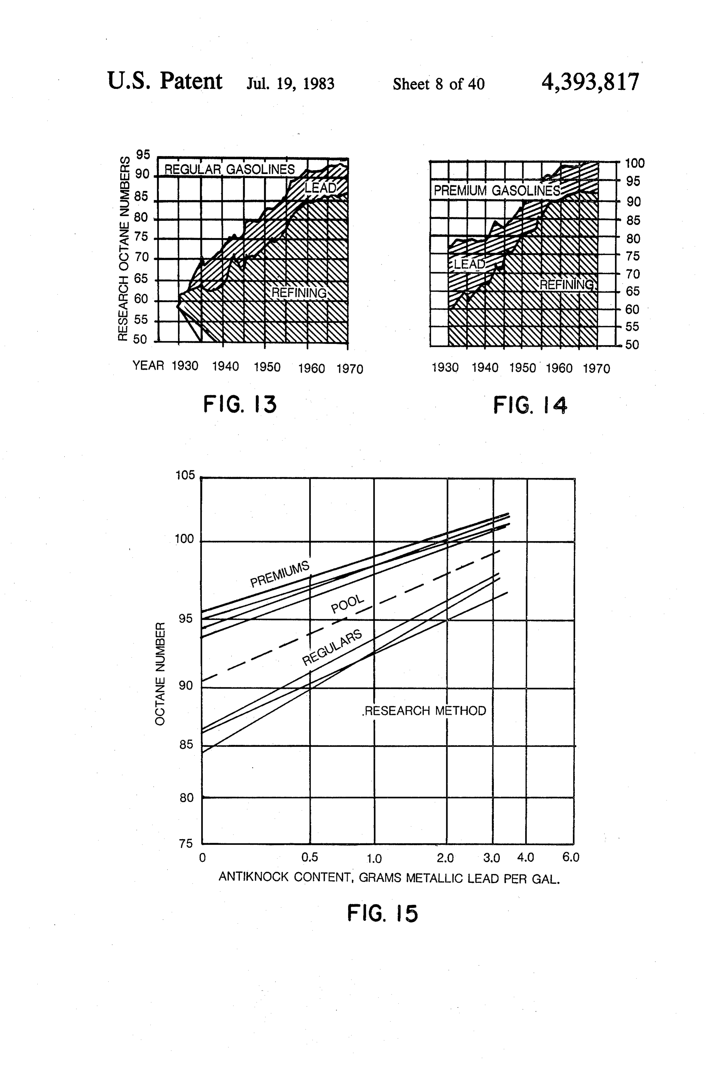
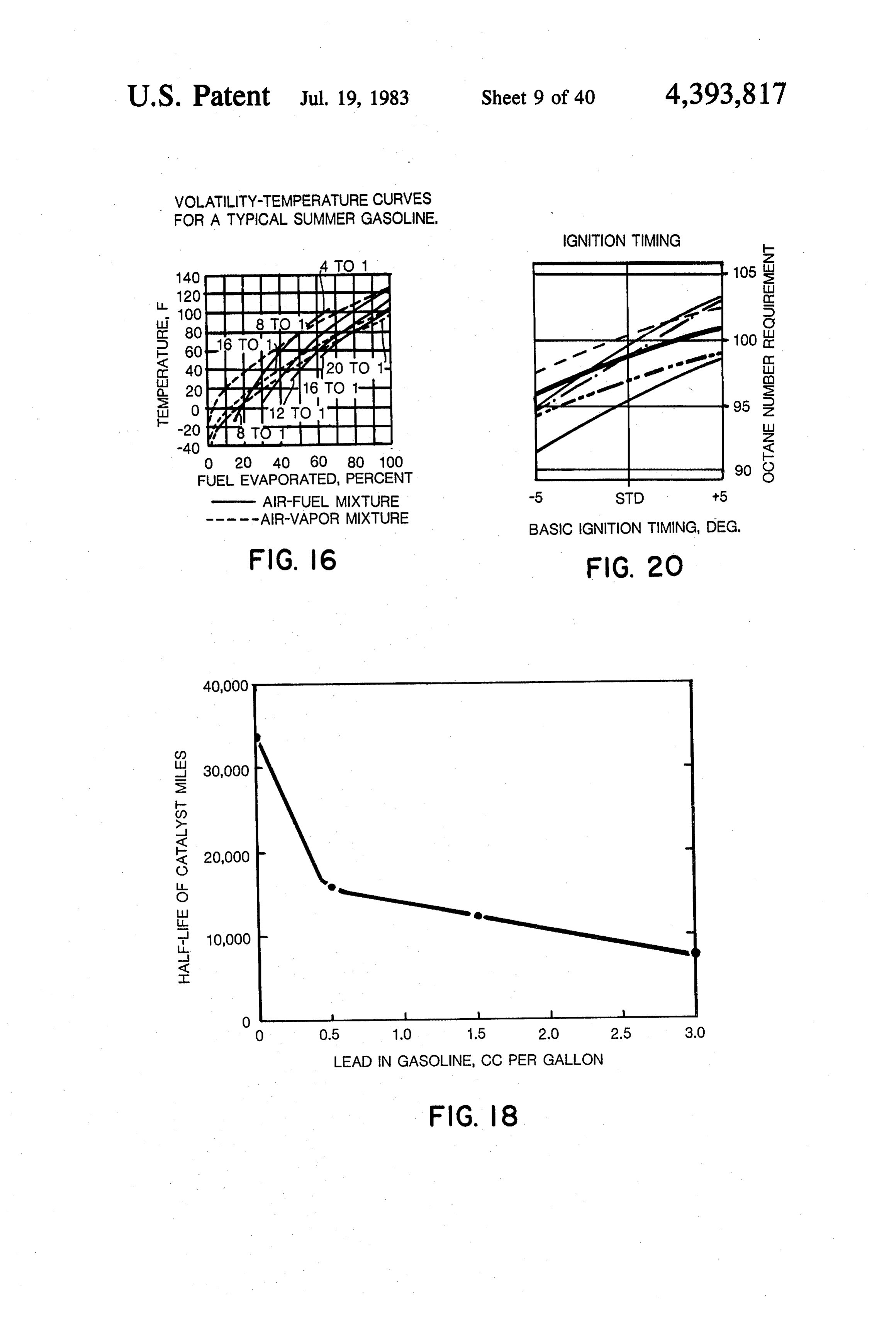
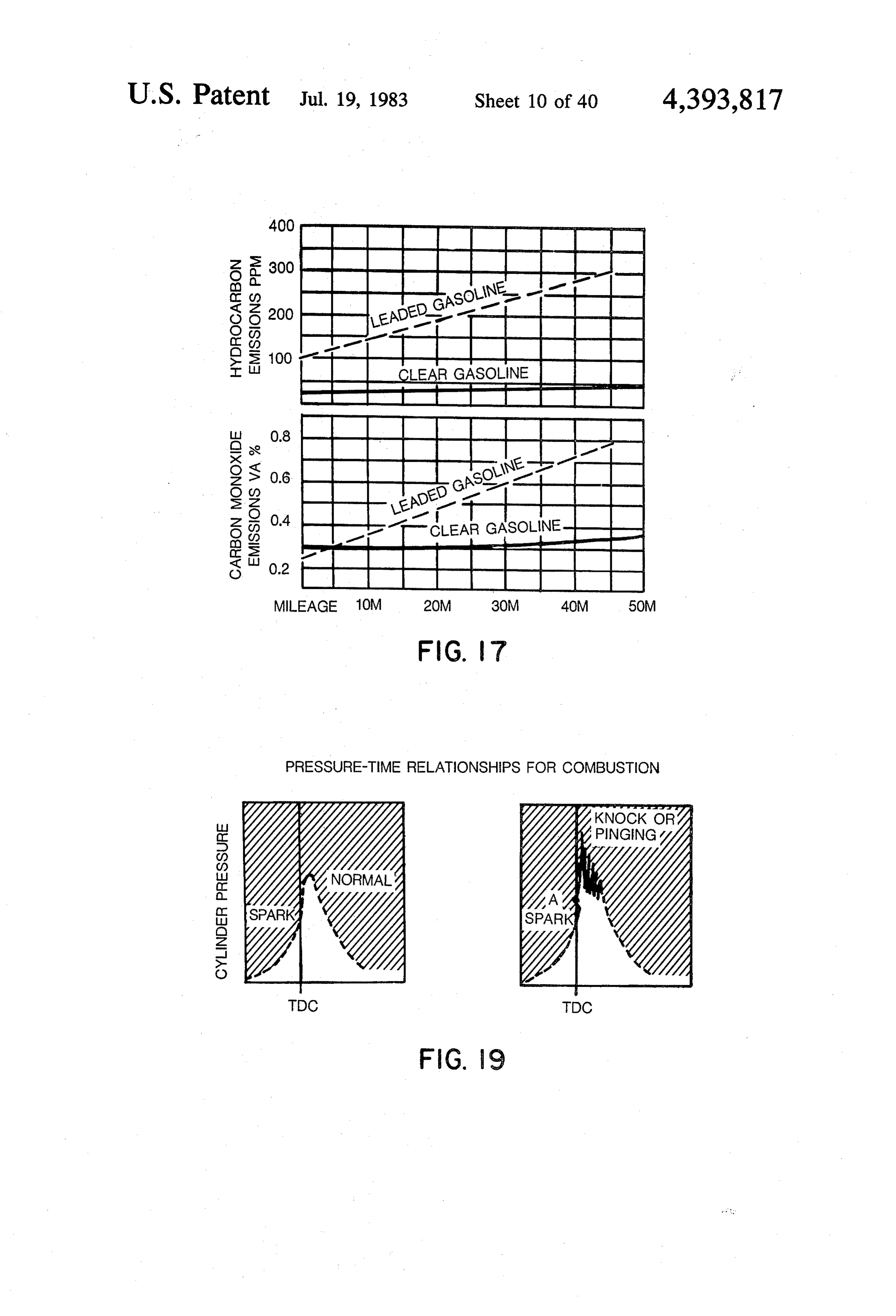
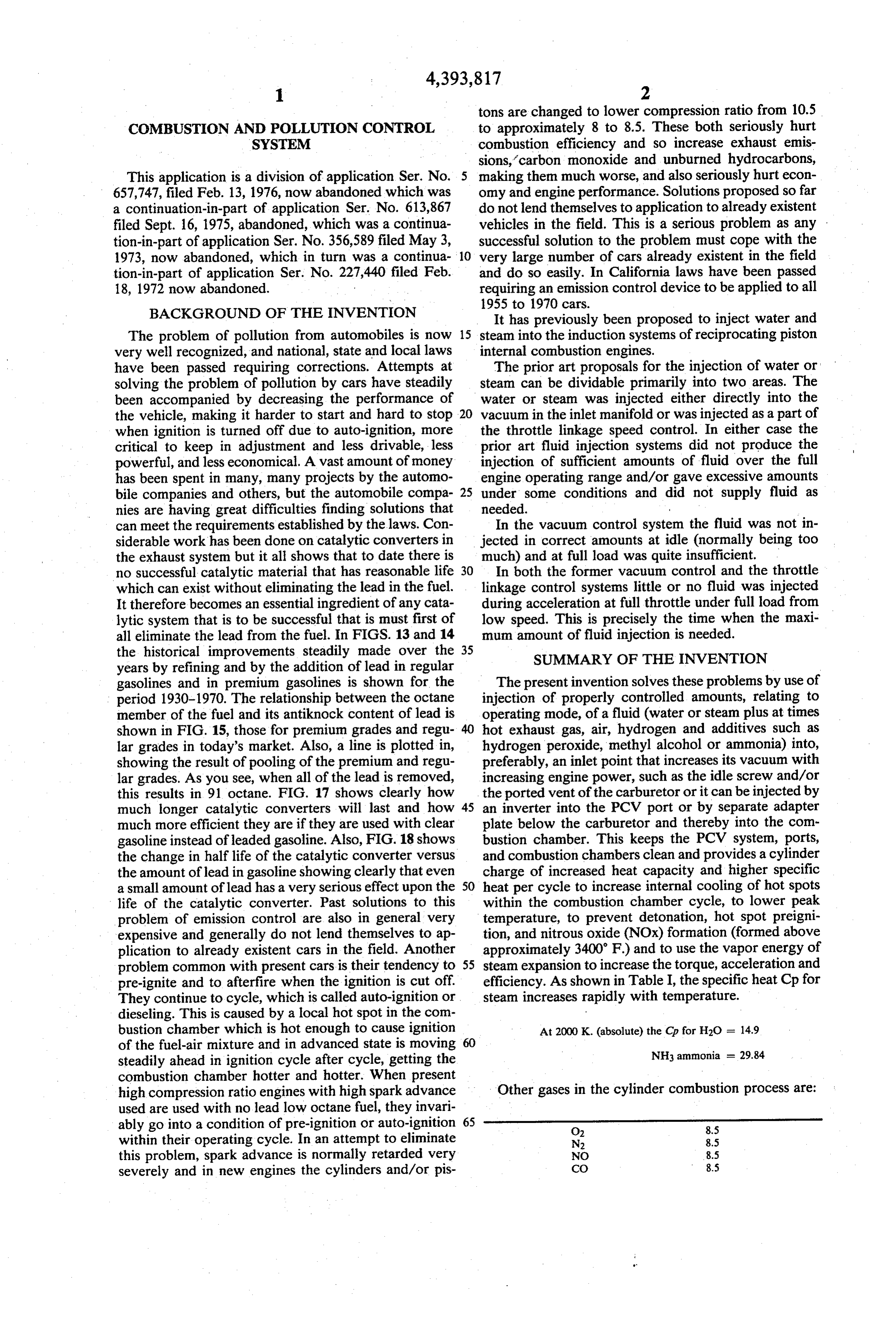
can meet the requirements established by the laws. Con In the vacuum control system the fluid was not in siderable work has been done on catalytic converters in jected in correct amounts at idle (normally being too the exhaust system but it all shows that to date there is much) and at full load was quite insufficient. no successful catalytic material that has reasonable life 30 In both the former vacuum control and the throttle which can exist without eliminating the lead in the fuel. linkage control systems little or no fluid was injected It therefore becomes an essential ingredient of any cata during acceleration at full throttle under full load from lytic system that is to be successful that is must first of low speed. This is precisely the time when the maxi all eliminate the lead from the fuel. In FIGS. 13 and 14 mum amount of fluid injection is needed. the historical improvements steadily made over the 35 SUMMARY OF THE INVENTION years by refining and by the addition of lead in regular gasolines and in premium gasolines is shown for the The present invention solves these problems by use of period 1930-1970. The relationship between the octane injection of properly controlled amounts, relating to member of the fuel and its antiknock content of lead is operating mode, of a fluid (water or steam plus at times shown in FIG. 15, those for premium grades and regu hot exhaust gas, air, hydrogen and additives such as lar grades in today's market. Also, a line is plotted in, hydrogen peroxide, methyl alcohol or ammonia) into, showing the result of pooling of the premium and regu preferably, an inlet point that increases its vacuum with lar grades. As you see, when all of the lead is removed, increasing engine power, such as the idle screw and/or this results in 91 octane. FIG. 17 shows clearly how the ported vent of the carburetor or it can be injected by much longer catalytic converters will last and how 45 an inverter into the PCV port or by separate adapter much more efficient they are if they are used with clear plate below the carburetor and thereby into the com gasoline instead of leaded gasoline. Also, FIG. 18 shows bustion chamber. This keeps the PCV system, ports, the change in half life of the catalytic converter versus and combustion chambers clean and provides a cylinder the amount of lead in gasoline showing clearly that even charge of increased heat capacity and higher specific a small amount of lead has a very serious effect upon the 50 heat per cycle to increase internal cooling of hot spots life of the catalytic converter. Past solutions to this within the combustion chamber cycle, to lower peak problem of emission control are also in general very temperature, to prevent detonation, hot spot preigni expensive and generally do not lend themselves to ap tion, and nitrous oxide (NOx) formation (formed above plication to already existent cars in the field. Another approximately 3400 F) and to use the vapor energy of problem common with present cars is their tendency to 55 steam expansion to increase the torque, acceleration and pre-ignite and to afterfire when the ignition is cut off. efficiency. As shown in Table I, the specific heat Cp for They continue to cycle, which is called auto-ignition or steam increases rapidly with temperature. dieseling. This is caused by a local hot spot in the com bustion chamber which is hot enough to cause ignition At 2000 K. (absolute) the Cp for H2O = 14.9 of the fuel-air mixture and in advanced state is moving steadily ahead in ignition cycle after cycle, getting the NH3 ammonia = 29.84 combustion chamber hotter and hotter. When present high compression ratio engines with high spark advance Other gases in the cylinder combustion process are: used are used with no lead low octane fuel, they invari ably go into a condition of pre-ignition or auto-ignition 65 O2 8.5 within their operating cycle. In an attempt to eliminate N2 8.5 this problem, spark advance is normally retarded very NO 8.5 severely and in new engines the cylinders and/or pis CO 8.5
Page 43
-continued the exhaust valve seat insert, the spark plug insert or a CO2 13.78 special flash boiler plug with flash boiler exposed at the combustion chamber inner surface (said plug located near or at the combustion chamber critical temperature
Thus, steam and ammonia each provide remarkable 5 area), act as a coolant, as well as provide more heat for internal cooling ability. As noted by the formula in the flash boiler. A heat pipe, as discussed later, could Table I, both ammonia and steam continue to increase provide
Cp as the square of absolute temperature increases and heat for the the access to this heat and provide maximum thermal-catalytic reactor when used.
so are very effective in snubbing peak damaging tem The system incorporates a spiral corrugated flex peratures. The data given is for moderate pressure. At O stainless steel tube to transfer exhaust gas to an adapter high pressure the heat capacities become appreciably greater. H2O2 (not shown) also provides high specific plate below the carburetor (FIG. 26). Superheated heat. steam is generated in one or more small stainless steel This system provides for increased quantity of high tubes run preferably inside, but, if not, then on the ex specific heat vapor to be added as the engine (or, 15 haust transfer line to permit heating the flash boiler fluid broadly, as the combustion cycle process) requires it flow in an increasing temperature gradient field as the due to temperature and/or load. This disclosed system flash boiler goes down the exhaust transfer line until the is applicable to all combustion processes (to increase flash boiler tube is extended into the active full very hot efficiency and reduce thermal and mechanical stress and exhaust gas, preferably in the exhaust manifold near the emissions): in internal combustion engines such as the 20 exhaust valve (see FIG. 22) and then returns through cycle reciprocating engine (as has been discussed); in the exhaust transfer tube (to keep the superheated sys internal combustion rotary engines as the Wankle, to tem hot) to the entrance point below the carburetor provide very much needed internal cooling, to protect (FIG. 26). Automatic variable orifice valves (FIGS. the critical rotor seals, to increase economy by opera 28-31) control the rate of flow of exhaust gas and flow tion at a near best F/A ratio, to obtain clean and com 25 of intermixed air to correctly automatically meet the plete combustion (present operation of these engines is engine needs; simultaneously the proper amount of very rich to obtain fuel cooling to protect rotor seals, steam to meet engine needs is fed to it by automatic but this gives very poor economy and emissions of control of the flash boiler exit vacuum (inc. FIGS. hydrocarbons and carbon monoxide are very high and 12-118), and use of engine fluctuating exhaust pressure require a substantial thermal or catalytic reactor to "rectified' by low mass, high frequency response check reduce to even today's emission requirements); in tur 30 valve bine and jet engines, to improve combustion efficiency in the (FIGS. 33 and 112-118) to provide peak pressure fluid tank (FIG. 32) supplemented, when needed, and reduce critically high temperatures, as of the tur by bine blades, to increase safety and reliability, reduce bly,asteam pump, either electric (FIGS. 6 and 32) or, prefera powered (FIGS. 5,37-39) from a flash boiler, maintenance, and reduce production costs and emis 35 plus, of course, control of the temperature flow around sions; external combustion engines such as steam en gines and Sterling engines, and any heating boiler or the flash boiler, together result in providing automati heating furnace to improve combustion efficiency, re cally the right amount of steam for each mode of opera duce emission pollutants, and reduce critical burner part tion: idle, acceleration, low speed cruise, high speed . temperatures to obtain extended life. cruise, and full throttle. The system has great inherent The amount of vapor injected at high temperature at stability. In idling it will automatically compensate for the input to cycle raises the vapor transition point that any condition changes to maintain the lean fuel/air ratio will occur during the exhaust cycle so that a condition which the engine was set to run at. The high specific can be obtained to recover part or all of the energy of energy of the combustion cycle provides stable low vaporization (condensation) within the working cycle speed idle (even two hundred rpm, if desired) almost to increase further the efficiency and not throw this 45 from start-up.
energy away in the exhaust. The emissions are decreased because the turbulence TABLE I and the high energy and specific heat of the steam and Gas Empirical Equation Cp at 2000 K. abs. exhaust added to the engine cycle provide excellent Monatomic Cp = 5.0 5.0 50 vaporization of the fuel and distribution of fuel vapor, H2 Cp = 6.5 + 0.0009T 8.3 air, exhaust gas, and steam. Also, the specific energy of O2, N2, NO, Cp = 6.5 + 0.0010T 8.5 the combustion cycle is increased to give more efficient CO, HCl,
HBr, HI and complete combustion. The steam acts to internally
Cl2, Br2, 12 Cp = 7.4 + 0.001T 9.4 heat the combustion at start-up and then as temperature H2O, H2S Cp = 8.81 - 0.0019 + 14.9 55 rises acts as an internal coolant, to lower peak surface 0.000002222 temperatures and combustion peak temperature. CO2, SO2 Cp = 7.0 + 0.007 1T - 13.76 Detonation and preignition are also prevented. This
NH3 Cp = 8.04 -- 0.0007T -- 29.84 more perfect combustion accounts for the decreased 0.0000051T2 CO and HC emissions. The formation of NOx is pre CH4 Cp = 7.5 + 0.005T 17.5 60 vented by the steam and exhaust gas keeping combus tion temperature below the formation temperature of
Since the energy used to vaporize the fluid is waste NOx (approximately 3400 F). Because combustion is energy at the exhaust any recovery of heat of vaporiza smoother the engine runs smoother and bearing loads tion provides substantial further efficiency increase. are decreased.
We are by the above substantially cooling the ex 65 It is recognized that exhaust gas recirculation as a haust. At the limit, greatest efficiency will be obtained method of nitrogen oxide control in internal combustion by exposing the flash boiler to waste heat at critical engines was tested by R. Kopa and A. Kimura at UCLA temperature points of the combustion chamber, while in 1960. To date attempts to use exhaust gas recircula
Page 44
tion have suffered from problems of drivability and of high inside combustion chamber temperatures. As an rapid deposit build-up in the intake system. alternate to this, a heat pipe could be placed around the I have invented a system to improve internal combus seat of the exhaust valve or in a part as described before tion engine performance and emission control using to the inside combustion chamber surface and the exten steam, and have tested and perfected it over the past sion of this heat pipe could be used to heat the flash several years. It uniquely combines in a control system boiler. The heat pipe was first put forward in 1942 by superheated steam, air, and recirculated exhaust gas Richard S. Gaugler of General Motors Corporation and with the fuel-air mixture in the induction system as more recently put to work by George M. Grover of the above described. I have, in fact, been using it in my Los Alamos Scientific Laboratory. The heat pipe is Lincoln Continental Mark III '69 (FIGS. 1 and 3) for 10 essentially a closed evacuated chamber whose inside approximately 6 years with no lead 91 octane fuel with walls are lined with a capillary structure or wick that is excellent results, and have substantially solved the emis saturated with a volatile fluid. The operation of the heat sion problem to the point of meeting standards years pipe combines two familiar principles of physics: vapor ahead. heat transfer and capillary action. Vapor heat transfer is Control of the vacuum spark advance is provided by 15 responsible for the transporting of the heat energy from exhaust pressure to provide full retard of vacuum ad the evaporator section at one end of the pipe to the vance (FIG. 3) during any instance of rapidly going to condenser section at the other end. The heat pipe capil full throttle, so as to aid in preventing detonation and lary action is responsible for the returning the con pre-ignition. Through the combination of these two densed or heat fluid back to the evaporator section to systems it is possible to use no lead fuel of 91 octane complete the cycle. Current development of the heat rating and still retain the high compression ratio, high pipe was described in May 1968 in Scientific American. spark advance condition, and therefore the high effi It is also proposed to use this heat pipe action to carry ciency of the present engine. In fact, the engine effi heat down into the working area of our thermal and ciency is even further increased beyond that of the catalytic reactor within the exhaust manifold and down original engine with its premium fuel by an amount in 25 at the gasket section between the exhaust manifold and total of up to over 60% in cents per mile. In the full the exhaust pipe. This is necessary to give the required system a catalytic reactor is used which is kept clean by high temperature and the required residence time in being kept at temperature throughout its operating flight at high temperature for completion of the com cycle by an ignition system consisting of either a contin bustion reaction.
uous spark system (FIGS. 5 and 51) or a thermal igniter 30 In one specific embodiment of the present invention (FIGS. 12 and 52) which are turned on the instant the the water tank is mounted in the engine compartment ignition of the engine is turned on. This also assures that above the engine to provide gravity feed. A maximum the pollutants which are maximum during the cold amount of gravity feed is obtained by placing the water starting cycle of the engine are burned in the exhaust tank high and by placing a flash boiler low in the engine reactor if they are not burned within the combustion 35 compartment.
cycle in the cylinder. The flash boiler is heated by the exhaust gas, and the As shown in FIG. 5, exhaust from the steam boost flow of water into the flash boiler is controlled by a fluid pressure pump is fed to the bimetal control element variable orifice flow control valve in response to the of the automatic choke system standard today in most exhaust gas temperature. As the temperature goes up, cars (instead of hot air from the intake manifold struc 40 the valve opens to permit more water to flow into the ture) as this provides very rapid removal (less than 30 flash boiler, and this produces more steam. Thus, the seconds) of the enrichment necessary to get vapor suffi amount of steam injected is controlled in response to the cient at cold temperatures to start any car (FIG. 21). By engine's need for the steam.
doing this we get the full benefit of the disclosed system Regulating the flow of the water, rather than the flow to operate lean almost immediately after starting due to 45 of the steam, simplifies the control and minimizes prob the recycle of heat energy in the form of exhaust and lems of high temperature corrosion. steam to give the needed fuel vaporization even with a Various constructions of the flash boiler can be used, lean mixture. depending on the installation and other factors. The disclosed system increases the engine efficiency. Ultrasonic energy is added to the steam injected. The This increase in efficiency is in part due to the increase 50 ultrasonic energy can be developed by the steam itself in the average temperature of the combustion cycle. by passing the steam through whistles, or the ultrasonic Engine efficiency increases as the temperature of the energy can be developed by other means. The ultra working fluid. Therefore anything that can be done to sonic energy improves mixing and distribution. raise the temperature of the steam that is put in the The invention also provides for the combination of engine will raise the efficiency of the engine for the 55 steam, catalysts and ultrasonic energy with the fuel-air normally anticipated amount of steam to be used in the mixture to produce hydrogen gas. The hydrogen gas cycle (30% steam by weight of fuel used). If the steam improves combustibility so that the engine can be oper in temperature is 1550' F. and the steam out tempera ated on a leaner fuel-air ratio. The hydrogen also im ture is 550 F. an over 11% increase in cycle efficiency proves heat transfer and distribution. occurs. It is proposed, therefore, that in new design the The prior art proposals injected water or steam into a flash boiler be arranged to have access to the full com decreasing vacuum field (max vacuum at idle and min at bustion temperature at the surface of the combustion full throttle). This is diametrically opposite to the de chamber. A flash boiler tube could be placed in a ther sired condition which is to inject into a field where the moplug having its surface on the surface of the inside of vacuum increases from zero at idle to max at full throt the combustion chamber. Alternately, it could be pro 65 tle.
vided in the design to have it as a part of the exhaust This ideal is approached in FIGS. 102-110 and FIG. valve seat to thereby provide cooling of the exhaust 121 with input through the idle screws. The small vac valve seat at the same time it picked up desired extra uum remaining at idle is made effectively zero by use of
Page 45
a standing column of water (equal to or slightly greater pump the fluid in direct relation to the various engine than the idle screw idle vac. in inches of water) con operating conditions.
nected at one end to the flash boiler input and at the Fluid injection apparatus and methods which incor other end to the fluidic drain valve. This system permits porate the structure and techniques described above use of a common tube connection to a resilient collaps and which are effective to function as described above, ible wall accelerator-decelerator reservoir to add or constitute specific objects of this invention. remove water flow to the fish boiler to match engine Other objects, advantages and features of my inven need for quantity and quality of steam under dynamic tion will become apparent from the following detailed change conditions. description of one preferred embodiment taken with the The use of a decreasing vacuum field to produce an 10 accompanying drawings.
increasing vacuum input effect for the fluid is shown in BRIEF DESCRIPTION OF THE DRAWINGS the inverter system, FIGS. 106-118. The inverter pro vides the ideal zero vacuum at idle (so no fluidic drain In the drawings:
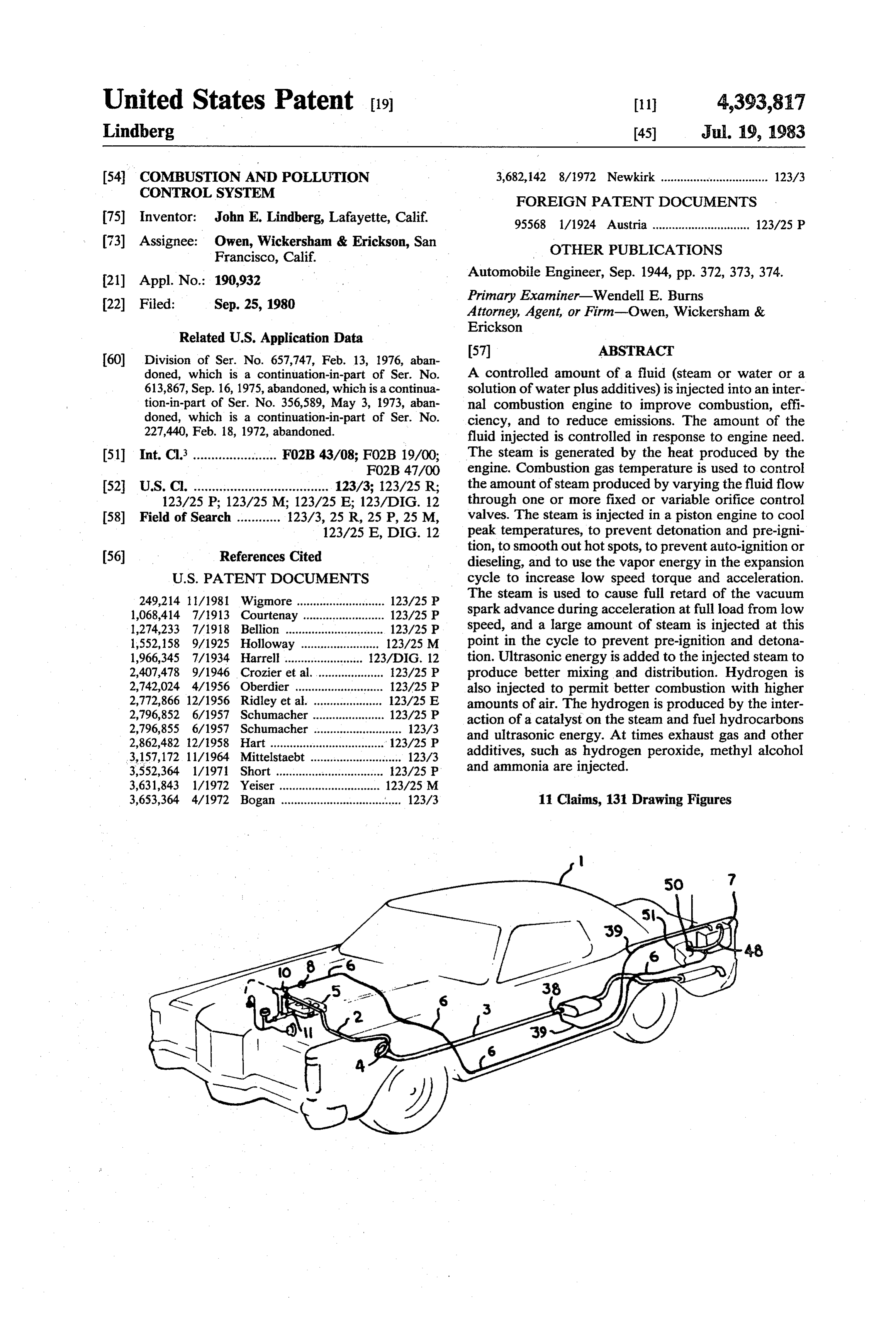
column is required). FIG. 1 is a phantom isometric view of a 1969 Conti As shown in FIG. 106, the vacuum continues to 15 nental Mark III car with one embodiment of the dis smoothly increase until full throttle is approached, closed combustion improvement and emission control where it drops off rapidly. As shown in FIGS. 106, 117 system installed.
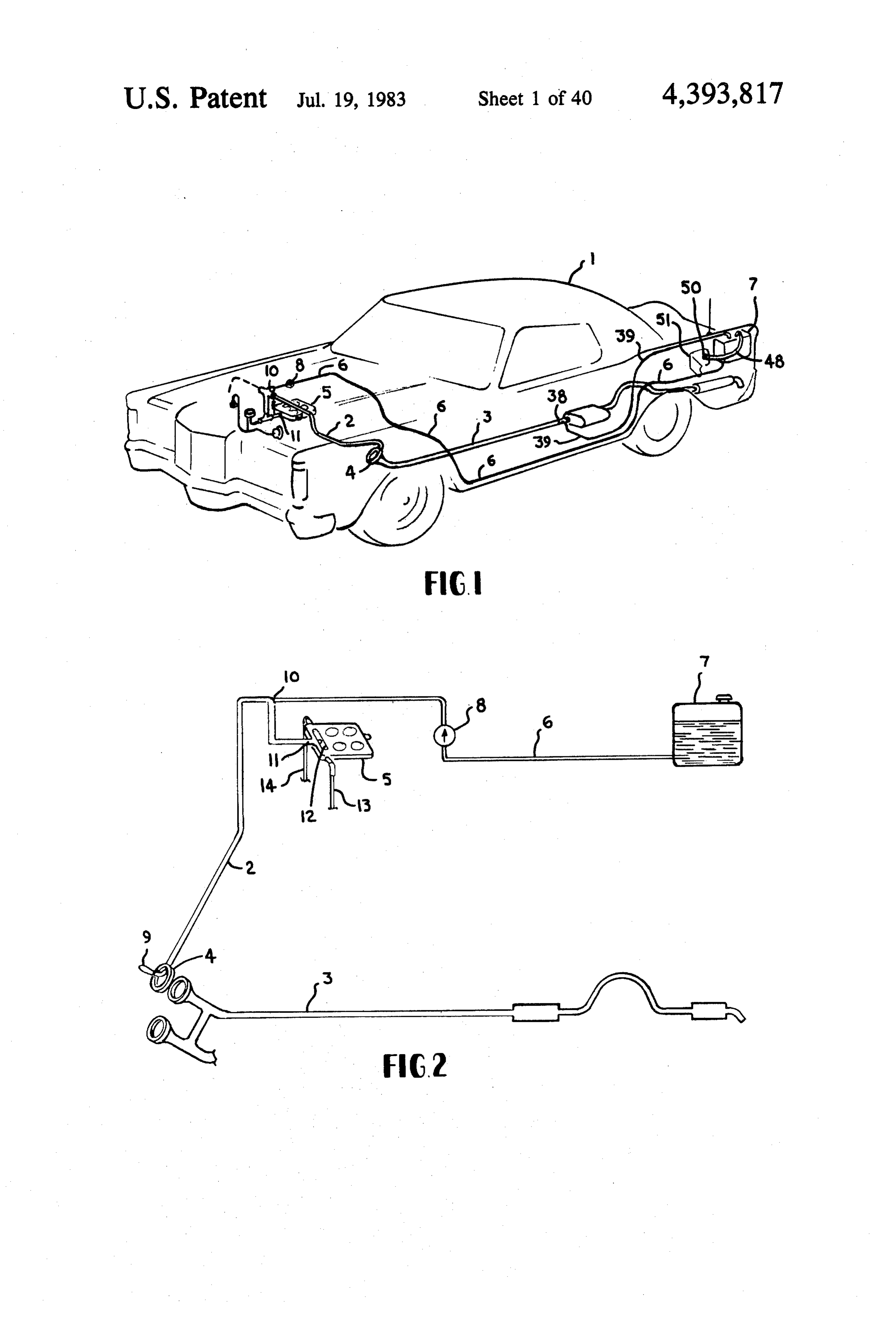
and 110 this is corrected by applying above the water FIG. 2 is a diagrammatic view partly in isometric of exhaust manifold total pressure either directly or 20 one simple form of the disclosed combustion and emis through a low inertia fluidic valve to half wave rectify sion control system.
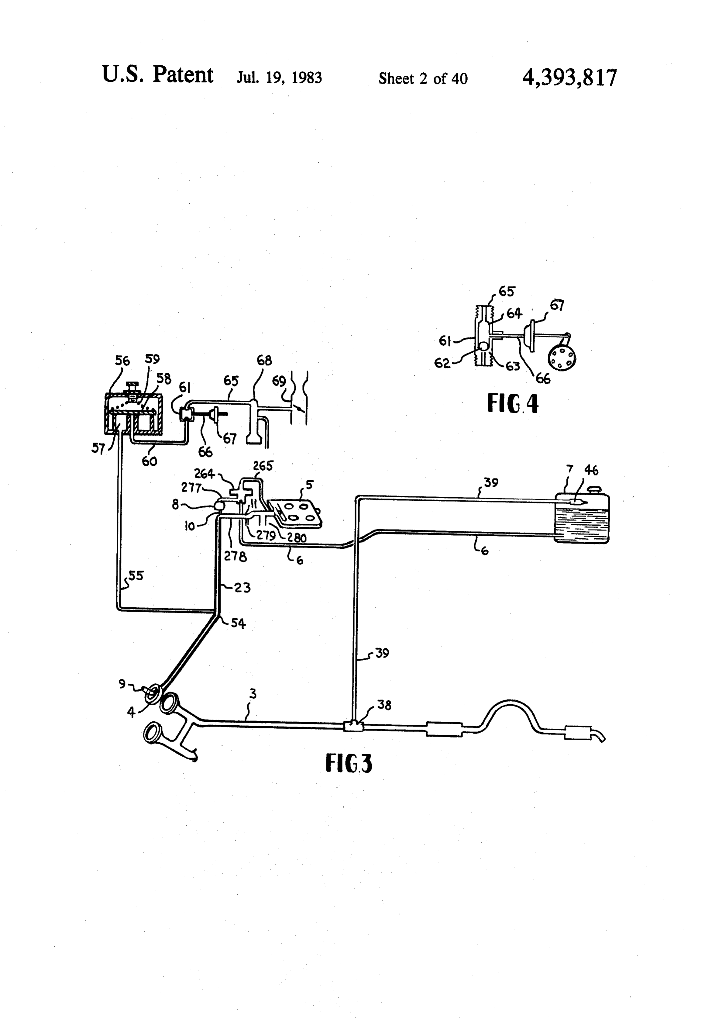
the alternating exhaust pressure and also applying this FIG. 3 is a diagrammatic view partly in isometric and exhaust pressure to the inverter. This provides an in partly in cross section of the basic emission and combus creasing exhaust pressure (super atmospheric) over the tion control system as installed in the car of FIG. I. The water to correct for the vacuum decrease at full throttle 25 system is the same as FIG. 2 with the addition of several noted above. The result is a steady increase in differen features such as the exhaust pressure feed system for the tial pressure of atmospheric total pressure over the tank fluid tank and the feature of exhaust pressure controlled water minus the total pressure at the fluid inlet point via retard of the vacuum spark advance system in accelera the inverter which starts at zero at idle and which stead tion.
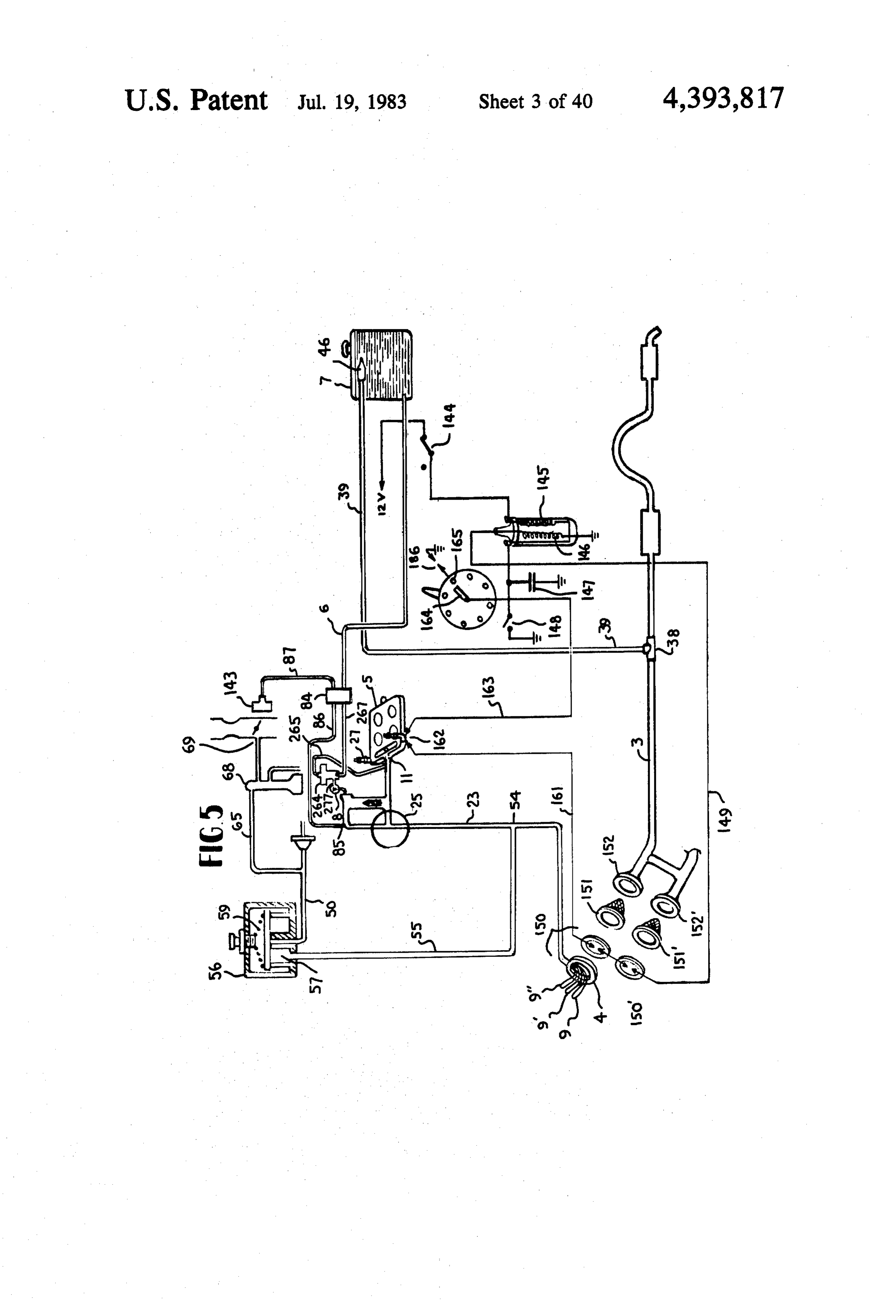
ily increases with increasing power to max at full throt FIG. 4 is a diagrammatic view partly in section of a tle. The inverter follows the power demand, giving zero detail of FIG.3 related to the exhaust controlled retard flow at idle and steadily increasing fluid flow with in system in the vacuum spark advance control system. creased power up to full throttle. On deceleration the FIG. 5 is a diagrammatic view of a combustion and fluid flow is fully cut off and any excess fluid is drained. emission control system as disclosed, similar to FIG. 3 On acceleration exhaust pressure over the top of tank 35 with the addition of a water acceleration pump and shut fluid provides the extra fluid needed during accelera off valve, and a steam powered pump to boost the pres tion. At engine off all fluid flow to the engine is in sure of the fluid feed to the flash boilers and the addition stantly cut off, and drainage for any possible fluid in the of spark ozone generator as a part of the feed into the engine fluid line is also provided. Air lean-out at engine induction system and the addition of a spark ignition cut-off is provided to aid in preventing dieseling (after thermal and catalytic reactor at the gasket between the fire). exhaust manifold and the exhaust pipe. The inverter also provides air bleed lean-out propor FIG. 6 is a diagrammatic view, partly in cross section tioned to power to provide the additional air lean-out and partly isometric, of a further form of the disclosed the engine is capable of using when operating with the invention basically similar to FIG. 5, but using an elec described invention to give best economy and minimum 45 tric pump instead of a steam pump.
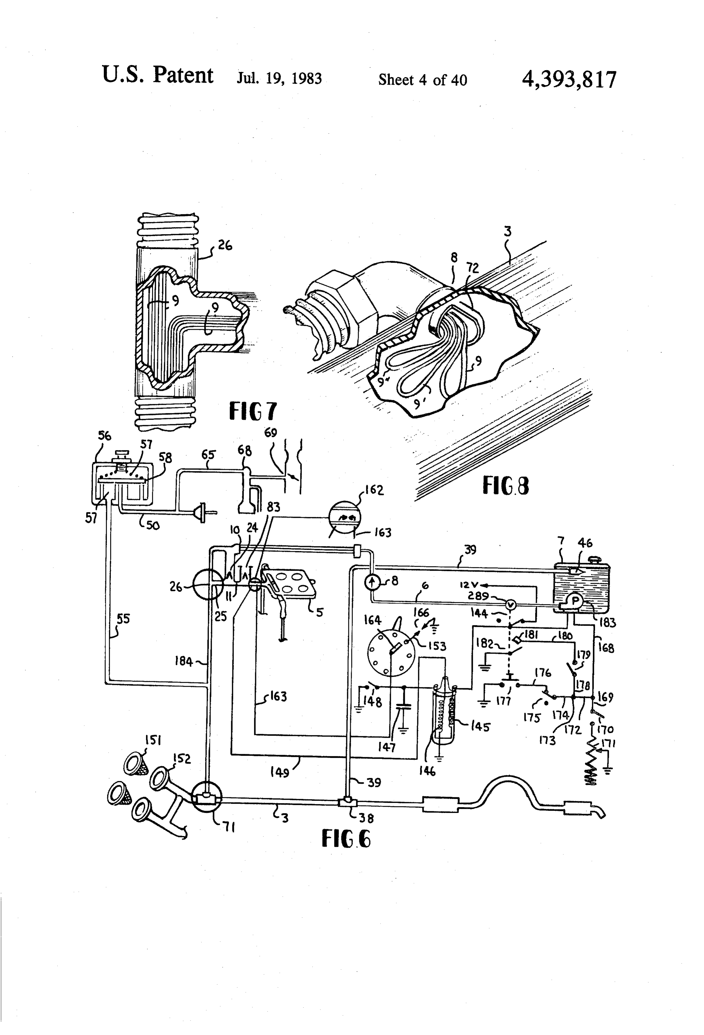
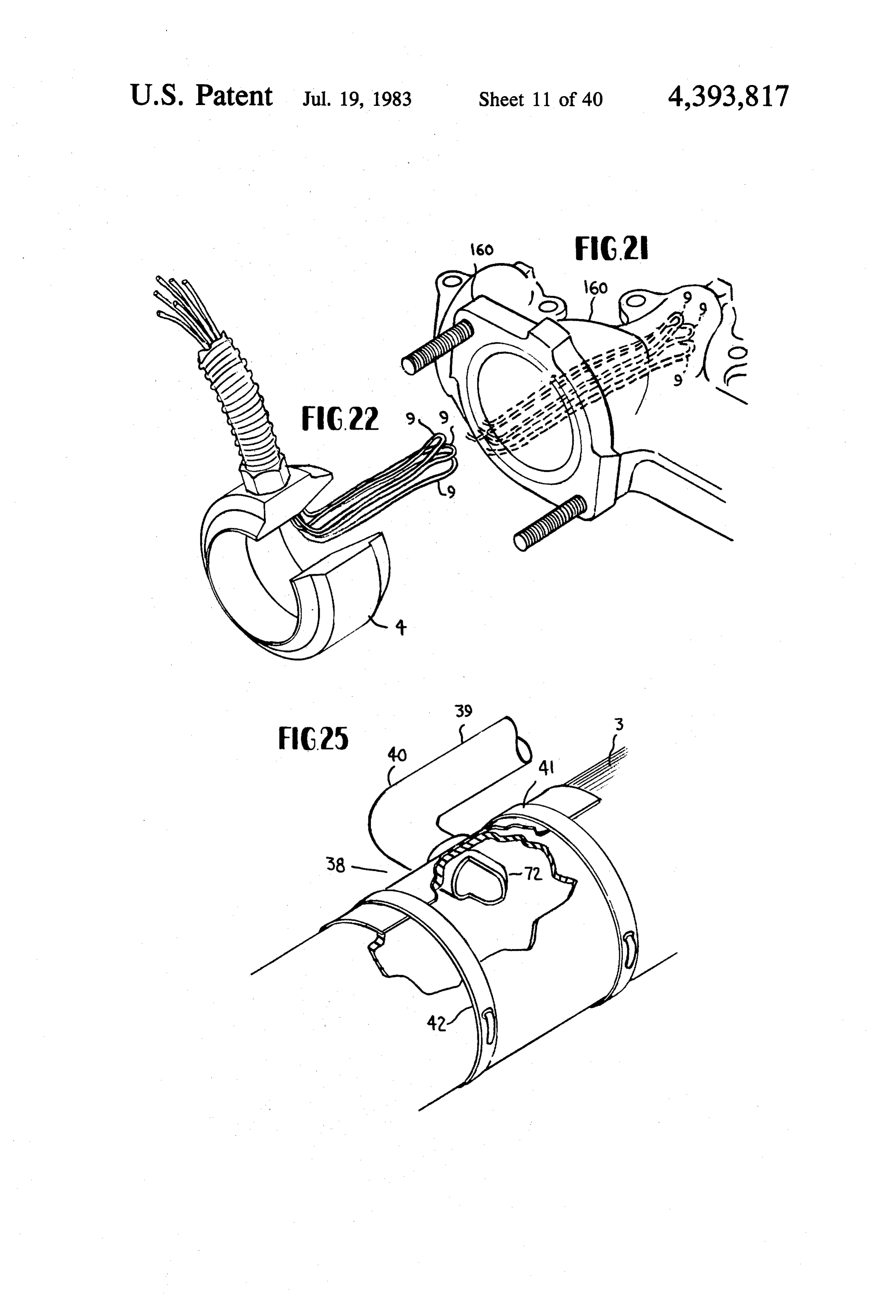
emissions. FIG. 7 is a detail of FIG. 6 of the exhaust transfer line The fluid flow, in one specific embodiment of the at the tee, isometric with a partly broken away cross present invention is controlled by a variable orifice section section to show the routing of the three flash valve responsive to heat flux produced by the engine so boilers.
that an increase in heat flux results in an increase in the SO FIG. 8 is an isometric view partly broken away to amount of fluid supplied to the engine. In this embodi show the three flash boilers extending from the exhaust ment of the invention a very desirable control function transfer line scoop into the exhaust pipe at the lower is produced on an increase in heat flux because of a end of the exhaust transfer tube of FIG. 6. regenerative feedback resulting from an increase in the FIG. 9 is a diagrammatic view, partly isometric and fluid flow. This regenerative effect is also effective on a 55 partly in cross section, of a further form of the invention decrease in heat flux to provide a rapid decrease in the similar to FIG. 3 with the addition of two separate fluid flow as a function of the decreasing fluid flow pressure tanks for fluid, each independently feeding a initially produced by the decreased heat flux. This heat separate flash boiler.
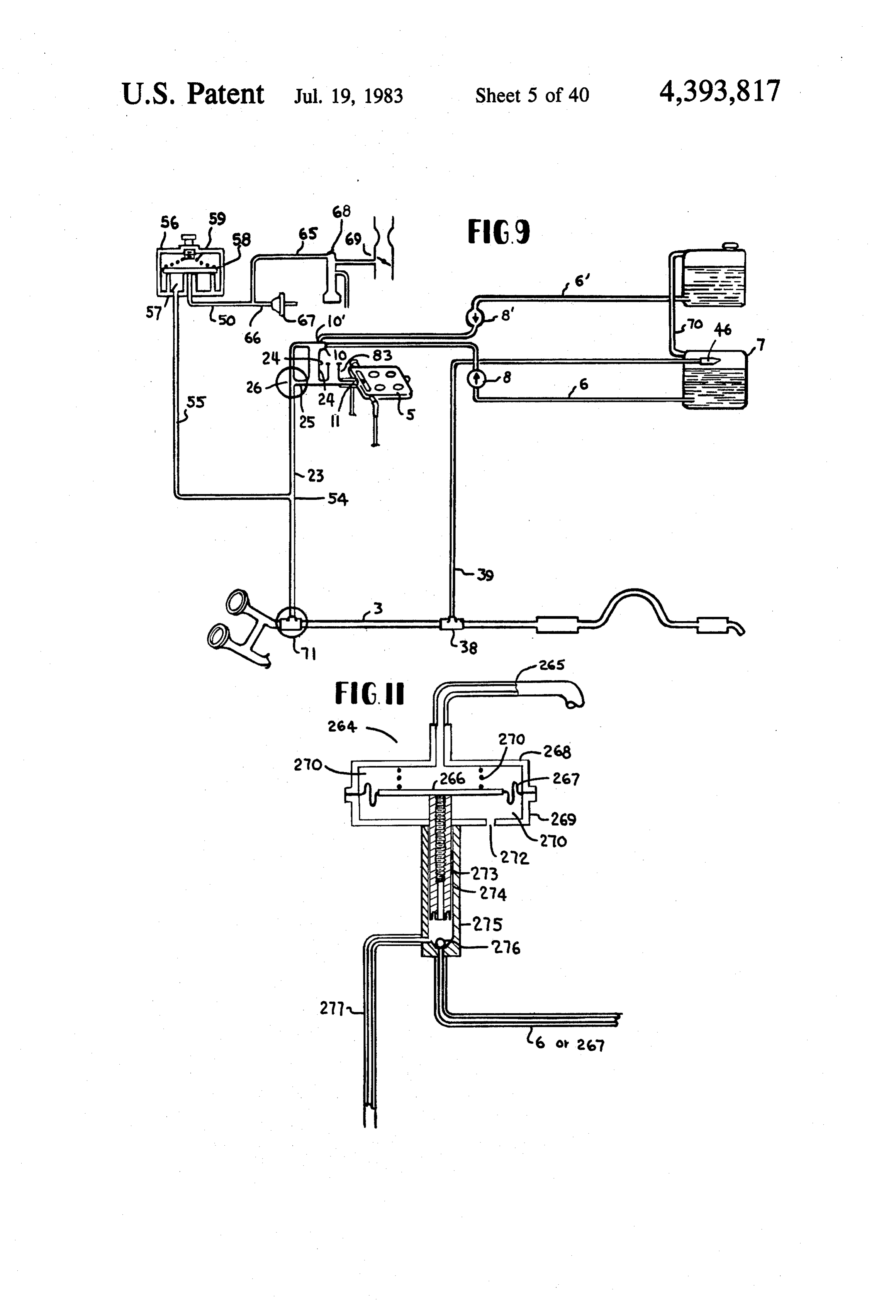
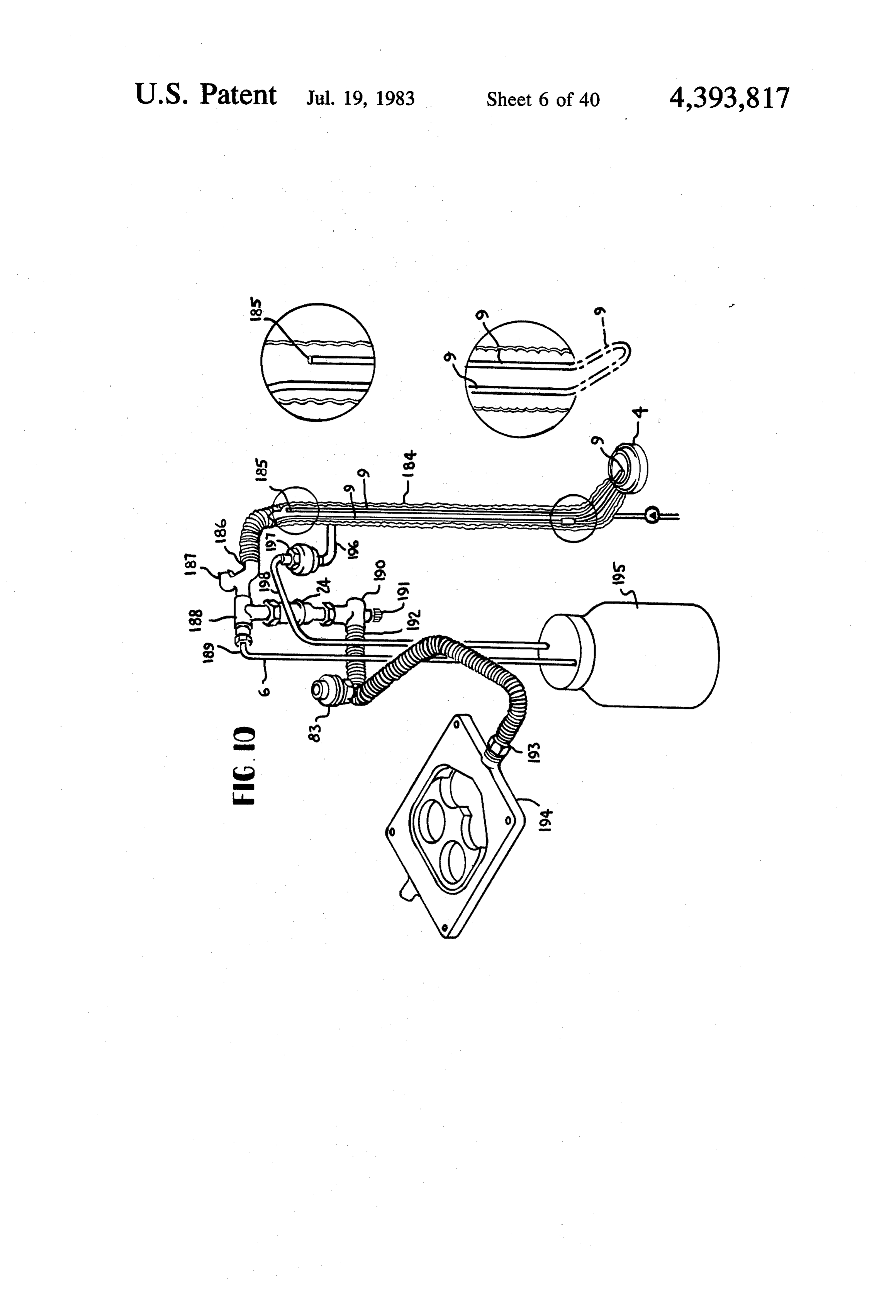
flux fluid flow responsive system coacts with dynamic FIG. 10 is an isometric view partly broken away to engine operating conditions to provide both a rapid show flash boiler details and is a further form of the control response and a response in the direction desired. invention disclosed herein. - In another specific embodiment of the invention a FIG. 11 is a diagrammatic view in cross section pulse pump is operated by the pulsations in the engine showing a vacuum operated water acceleration pump exhaust gas pressure and is effective to pump water (or and cut off valve as used in FIGS. 3 and 4 in practice of a mixture of water, fuel and air) to a thermal control 65 the invention disclosed herein.
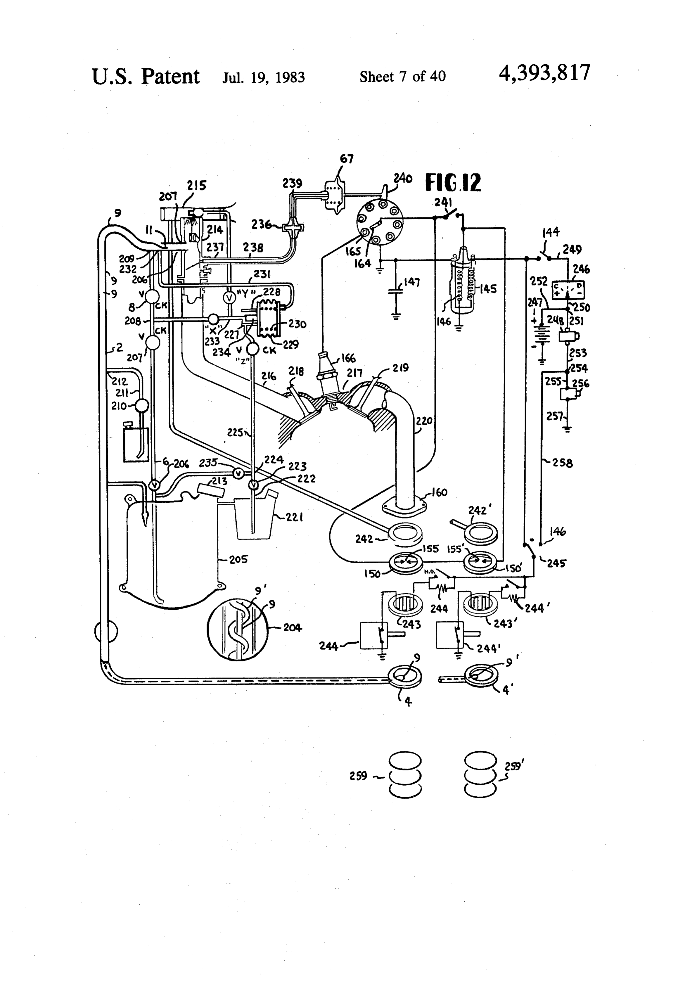
valve (or to a reactor in the case of a mixture of pumped FIG. 12 is a further form of the invention shown in water, fuel and air) using the power available from the diagrammatic view partly in cross section and partly engine exhaust pressure. The pulse pump is effective to isometric.
Page 46
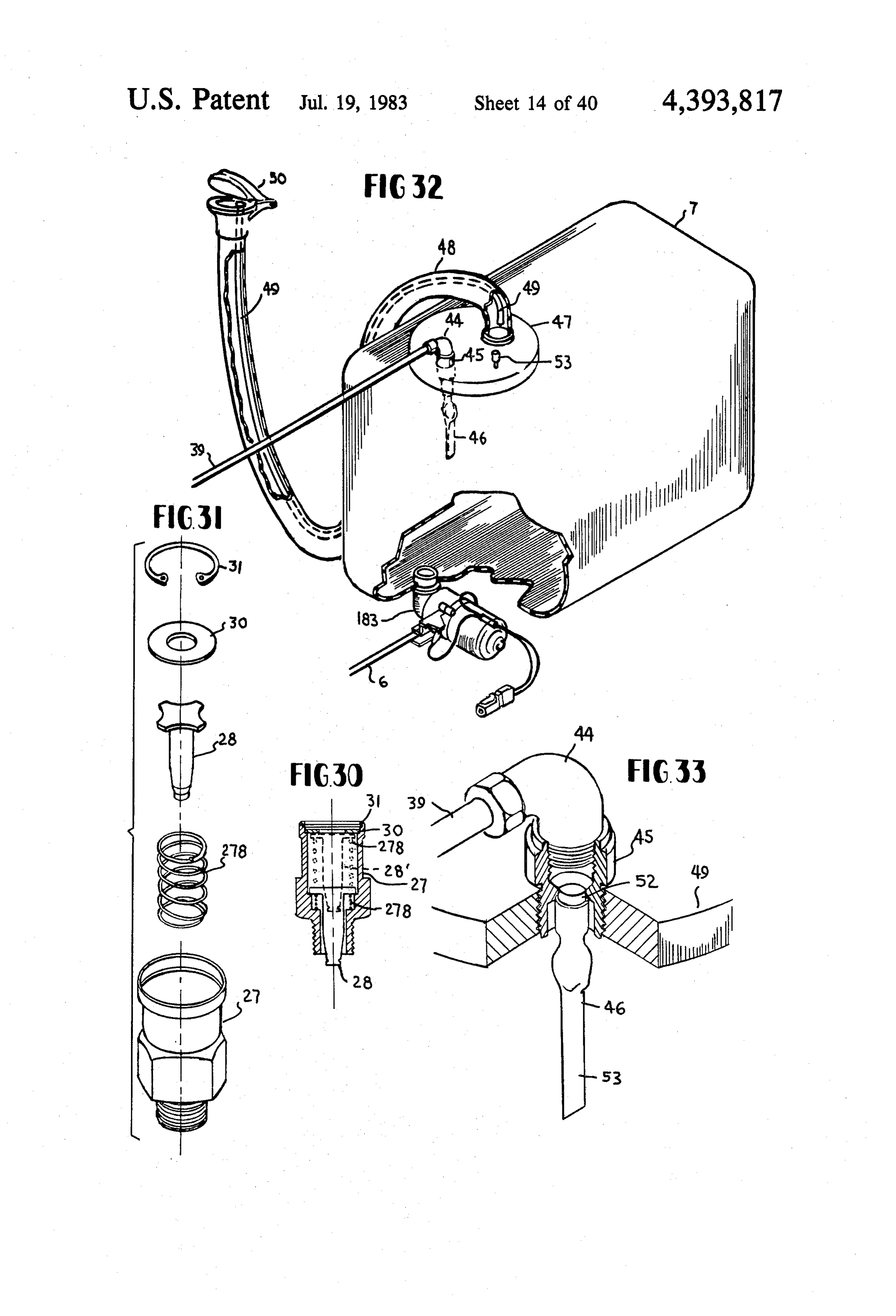
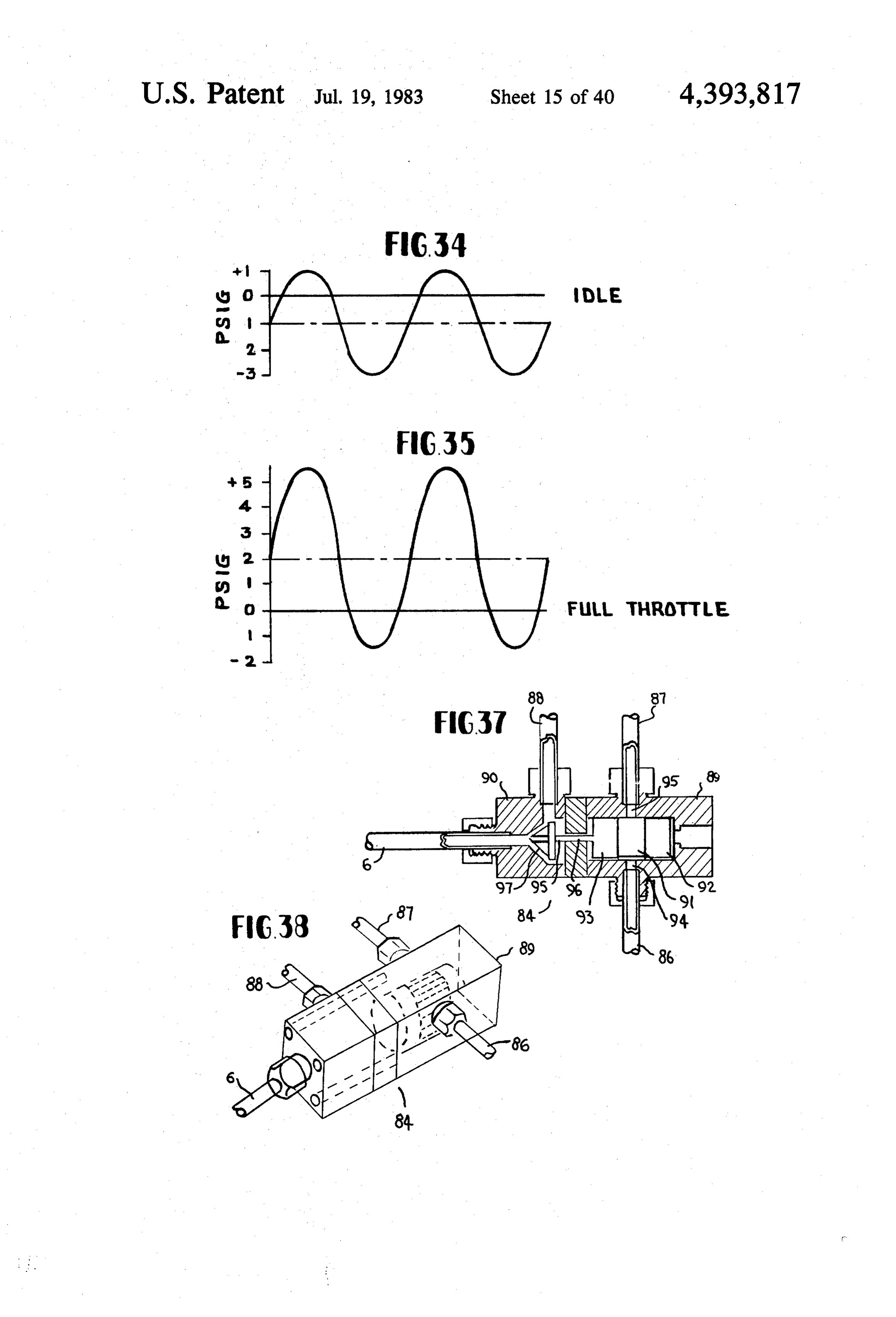
FIG. 13 is a graph showing the steady improvements FIG. 32 is a diagram in isometric, with a section made in automotive regular gasolines as a result of the broken away to show interior detail of the fluid tank improvements in refining and by the addition of lead in used in the disclosed invention. research octane number through the period 1930 to FIG.33 is an isometric view in cutaway cross section 1970, to show detail of the "exhaust pressure rectifier' used in FIG. 14 is a graph showing the steady improvements pressurizing the fluid tank in FIG. 32. in automotive premium fuels made by refining and by FIG. 34 shows a plot of the alternating exhaust pres the addition of lead in increased research octane num sure in p.s.i.g. versus time under idle condition (no time bers for the periods 1930 to 1970. scale intended). - FIG. 15 is a graph showing the change in octane O FIG. 35 shows the alternating exhaust pressure wave number versus the amount of antiknock metallic lead versus time in p.s.i.g. at full throttle (no time scale in added per gallon for automotive fuels of regular grade tended).
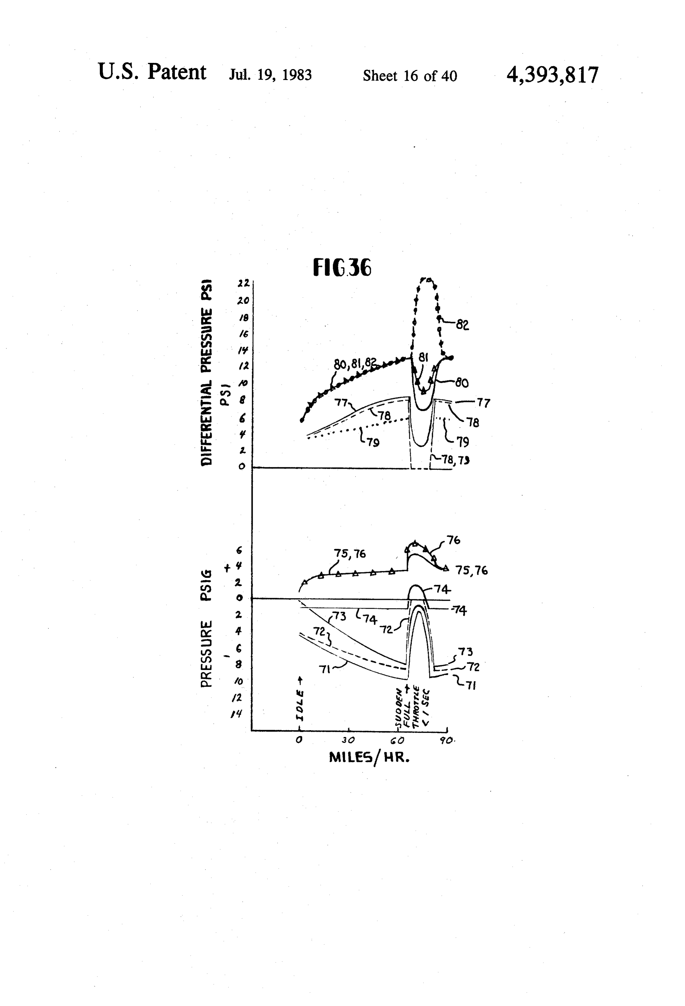
and of premium grade and also includes a plot of the FIG. 36 is a plot in the lower part of pressure in result of pooling all premium and regular grades. p.s.i.g. positive and negative, versus car miles per hour FIG. 16 is a graph of fuel volatility vs. temperature 15 speed showing the exhaust gas pressure, water pressure, for a typical summer automotive gasoline. and steam pressure. The upper plot of the same figure is FIG. 17 is two graphs to show the deterioration of a the differential pressure which is a replot of the lower catalytic converter in its ability to remove hydrocarbon figures in p.s.i.g. versus car miles per hour, again of the emissions in parts per million and carbon monoxide exhaust pressure, water pressure, and steam pressure, all emissions in volume percent versus mileage in miles 20 as used in the disclosed invention.
from zero to fifty thousand miles. FIG. 37 is a drawing in cross section showing the FIG. 18 is a diagram to show the half life of a catalyst details of a steam turbine driving a fluid turbine to boost in miles versus the amount of lead in the gasoline in cc's the pressure of the flash boiler feed system. per gallon. FIG. 38 is an isometric view of FIG. 37 as used in the FIG. 19 is a plot of the pressure time relationship for 25 proposed invention.
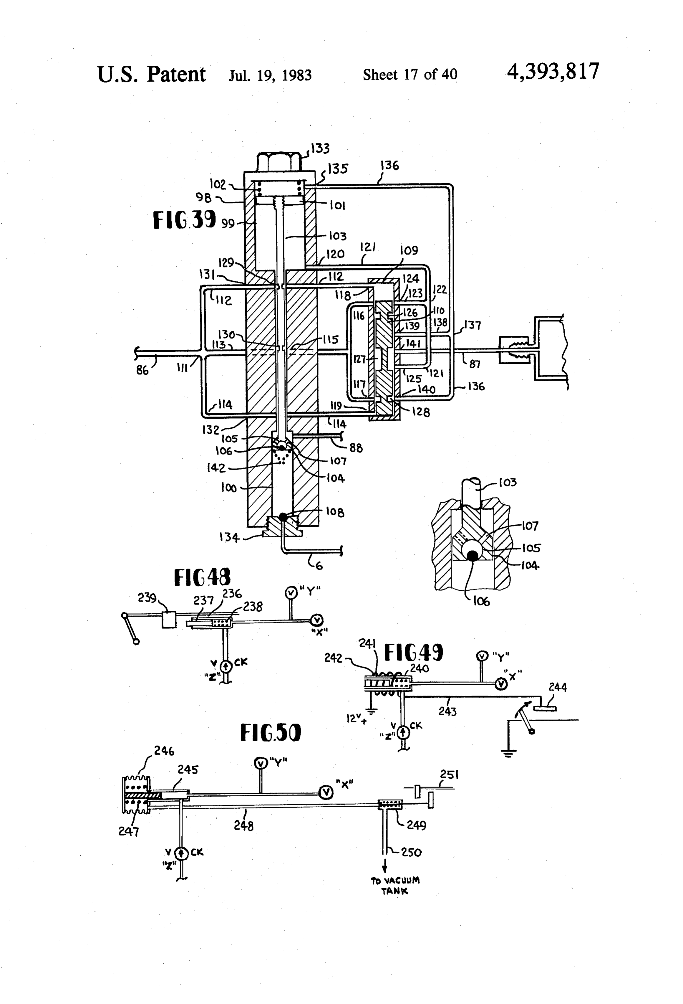
combustion for normal combustion and for knocking or detonating combustion. Pressure is plotted vertically tionFIG. of 39 is a diagrammatic view partly in cross sec a double acting steam powered fluid pump to and degrees crank angle is horizontal. boost the flash boiler feed system pressure as used in the FIG. 20 is a diagram to show the effects of ignition timing on octane number requirement of various typical 30 disclosed invention.
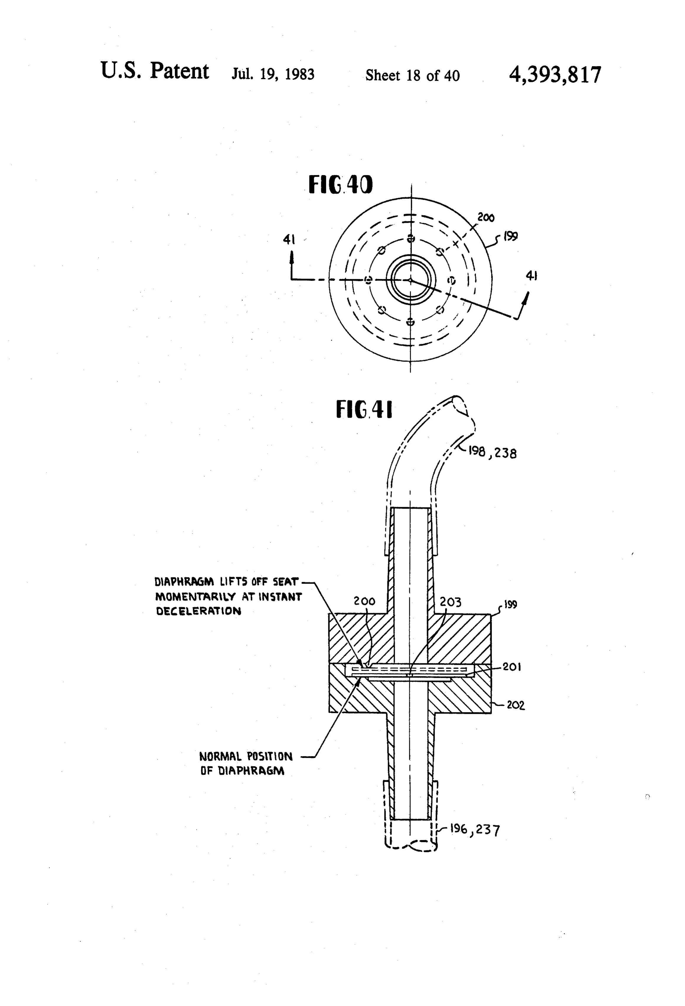
FIG. 40 is a plan view of a vacuum spark advance engines.
FIG. 21 is an isometric view of a typical automotive rateFIG. control valve.
41 is a cross sectional view along section line exhaust manifold from the exhaust flange side showing 41-41 of FIG. 40 advance rate control valve useful in in phantom the location of the flash boilers. the disclosed invention.
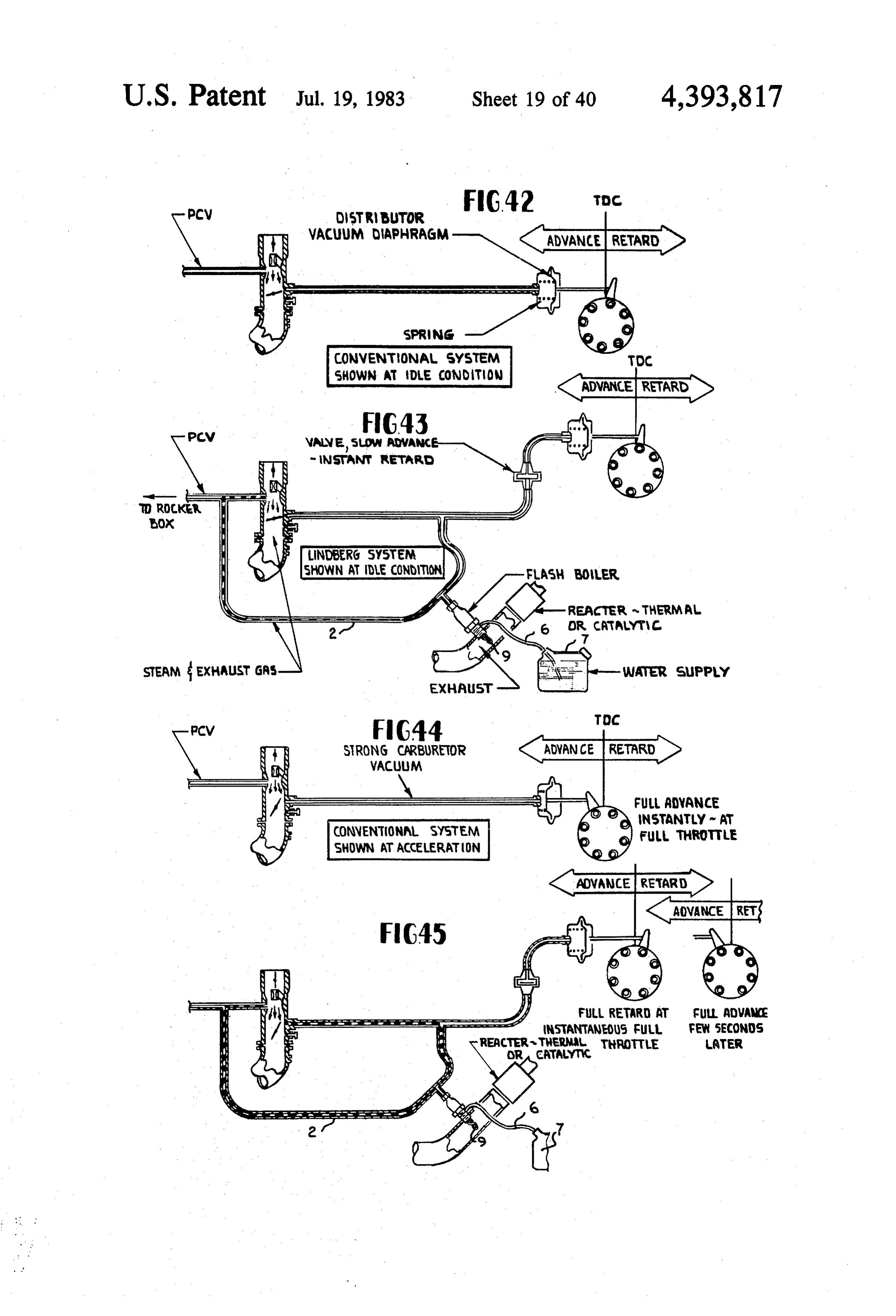
FIG. 22 is an isometric view partly in section of the 35
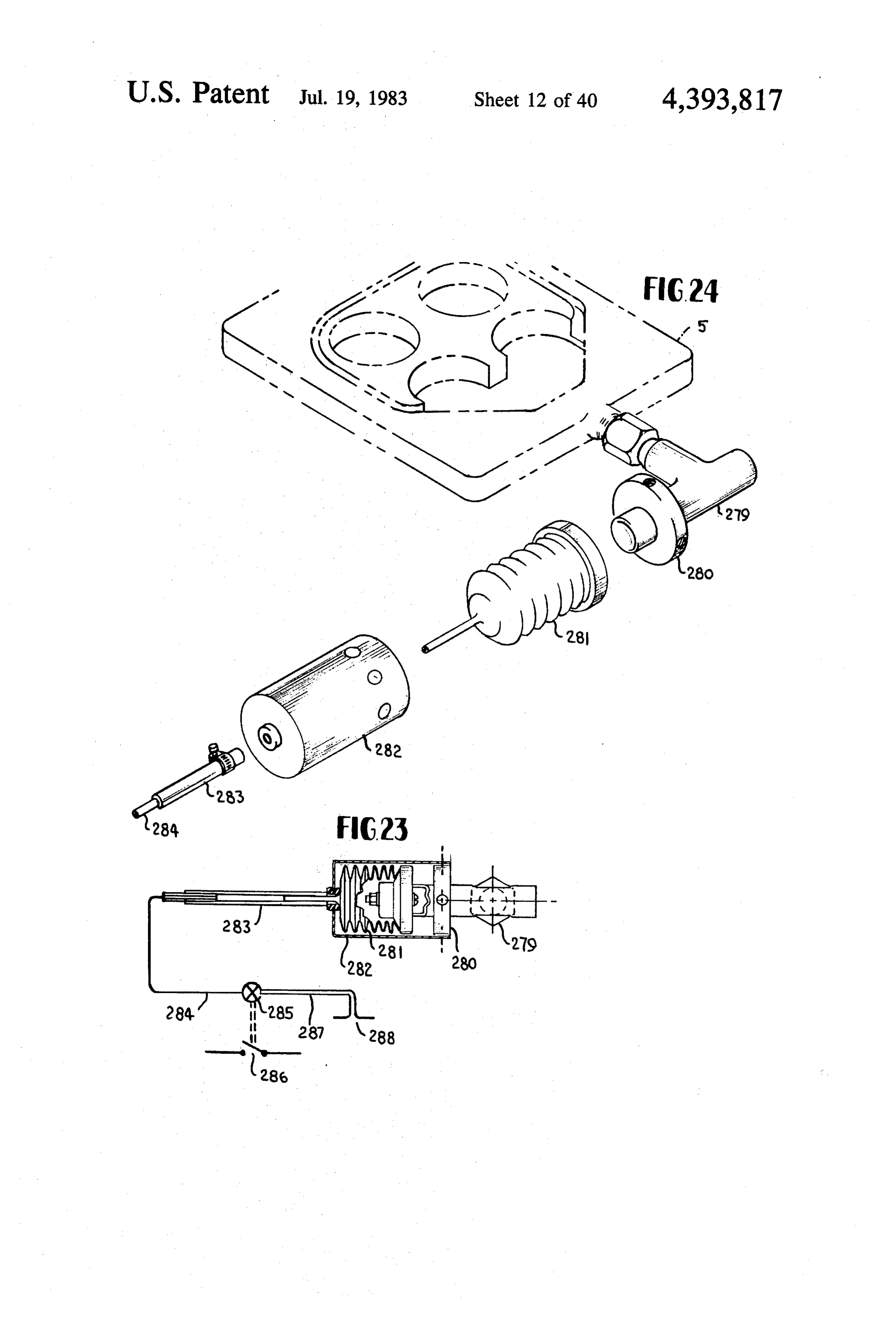
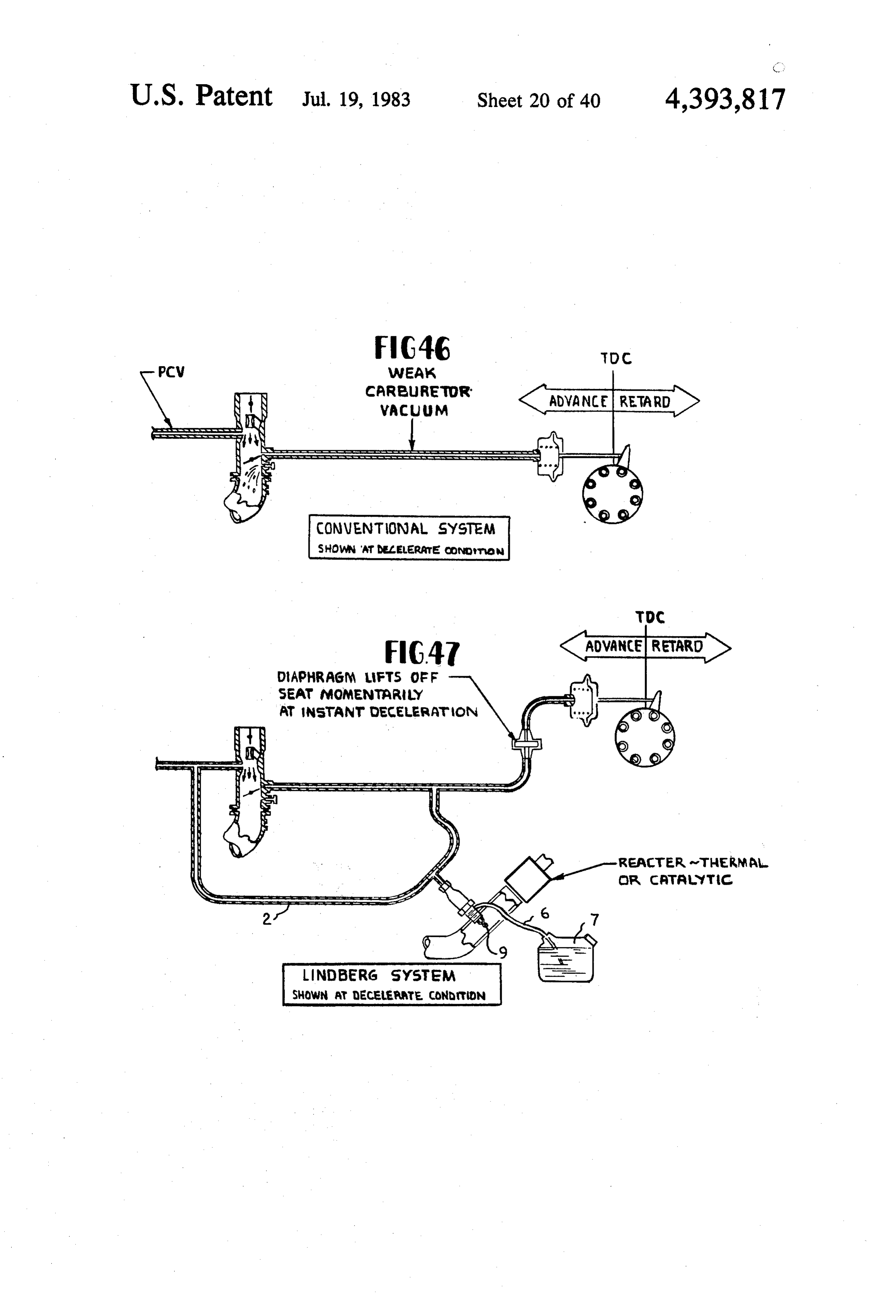
FIG. 42 is a diagrammatic drawing in part in cross end of our exhaust transfer line connected to the mani fold to exhaust pipe gasket showing the feed through of, spark section of a conventional system showing the vacuum in this case, three flash boilers extending upward into advance system at idle condition. the exhaust manifold, and is shown in assembly ex disclosed FIG. 43 is a diagram partly in cross section of the ploded relationship to the exhaust manifold of FIG. 21. 40 condition.invention advance rate control system at idle FIG. 23 is a diagrammatic view partly in section of a vacuum lean out valve to cut engine combustion at tionFIG. 44 is similar to FIG. 42, shown under accelera condition.
ignition off without afterfire. FIG. 45 is similar to FIG. 43 but shown under accel FIG. 24 is an exploded view of the valve of FIG. 23. erator
FIG. 25 is an isometric view of the exhaust pressure 45 FIG.condition.
46 is similar to FIG. 42 but shown under the scoop used to provide "total exhaust pressure' to the decelerate condition.
fluid tank.
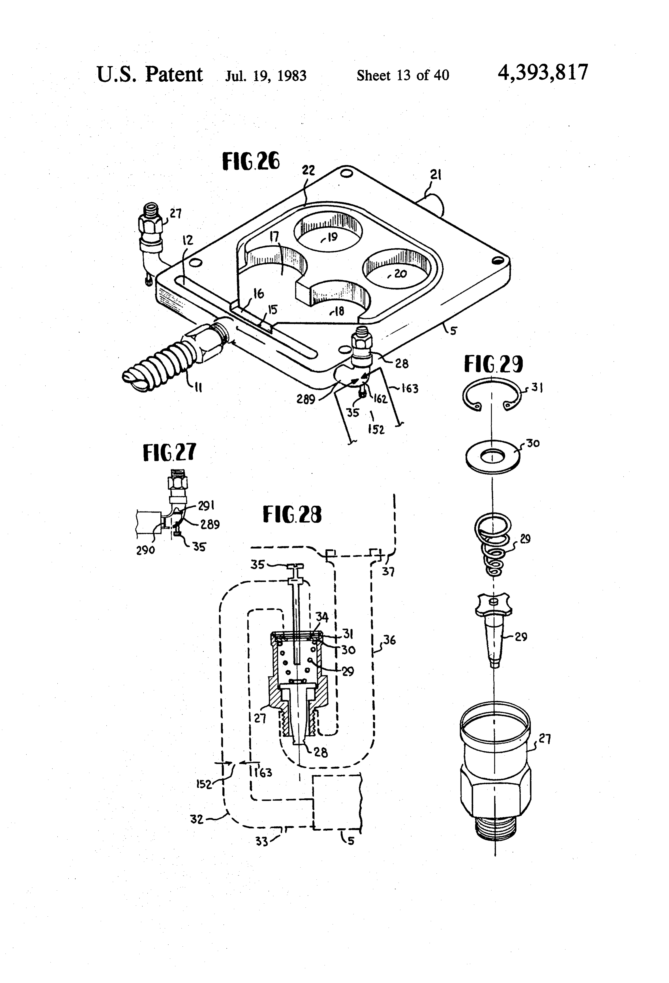
FIG. 26 is an isometric view of the adapter plate used FIG. 47 is similar to FIG. 43 but shown under decel between the carburetor and the intake manifold and it erate condition.
provides the PCV connection and also provides for 50 driven FIG. 48 is a diagrammatic view of a mechanically input of the exhaust gas, steam, and air provided in the acceleration boost pump for use in the disposed disclosed invention. invention and as specifically shown in detail for applica FIG. 27 is a detail partly in section of the air variable tionFIG.
49 is an electrically driven fluid boost accelera orifice valve connection to the adapter plate shown in
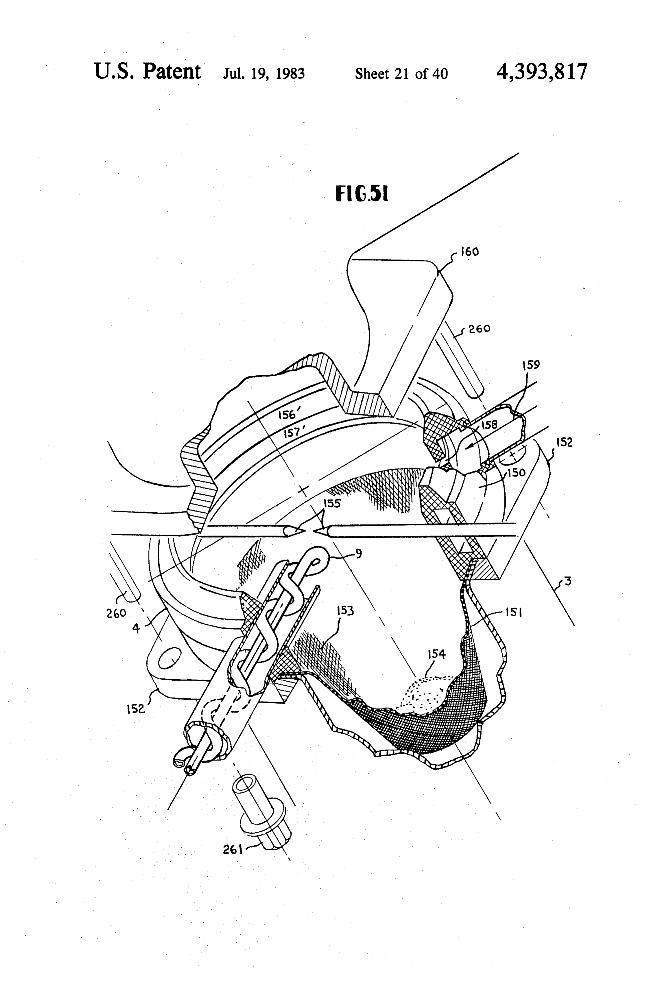
FIG. 26. 55 tion pump for use in the disclosed invention and as FIG. 28 is a diagram in cross section and partly in specifically set for application to FIG. 12. phantom showing the variable orifice valve and its basic FIG.50 is a vacuum powered fluid accleration pump installation as used in the disclosed invention. used in the application of the present invention and as FIG. 29 is a diagram in isometric form exploded to specifically set for application to FIG. 12. show the various parts in their relationship to each FIG. 51 is an isometric drawing partly in cross sec other of the variable orifice valve as shown in FIG. 28. tion and partly broken away showing a spark ignited FIG. 30 is a figure in cross section and phantom thermal and catalytic converter for installation at the showing a variable orifice valve showing a different manifold to exhaust pipe gasket for use in the disclosed variable orifice valve that can also, in some cases, be invention.
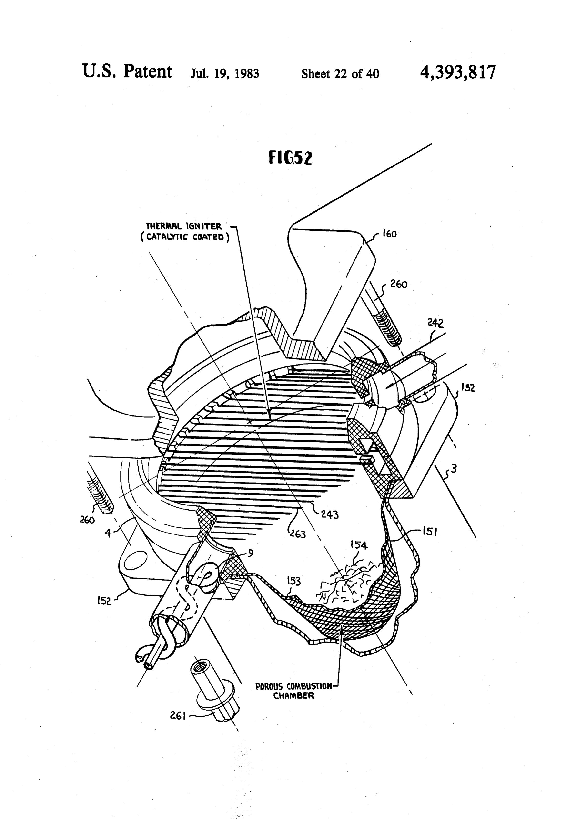
used in the disclosed invention. 65 FIG. 52 is an isometric view partly in cross section FIG. 31 is a diagram in isometric and exploded to and partly broken away to show details of a thermal show the relationship of the parts of the variable orifice igniter and catalytic and thermal reactor for installation valve as shown in FIG. 30. at the exhaust gasket between the exhaust manifold and
Page 47
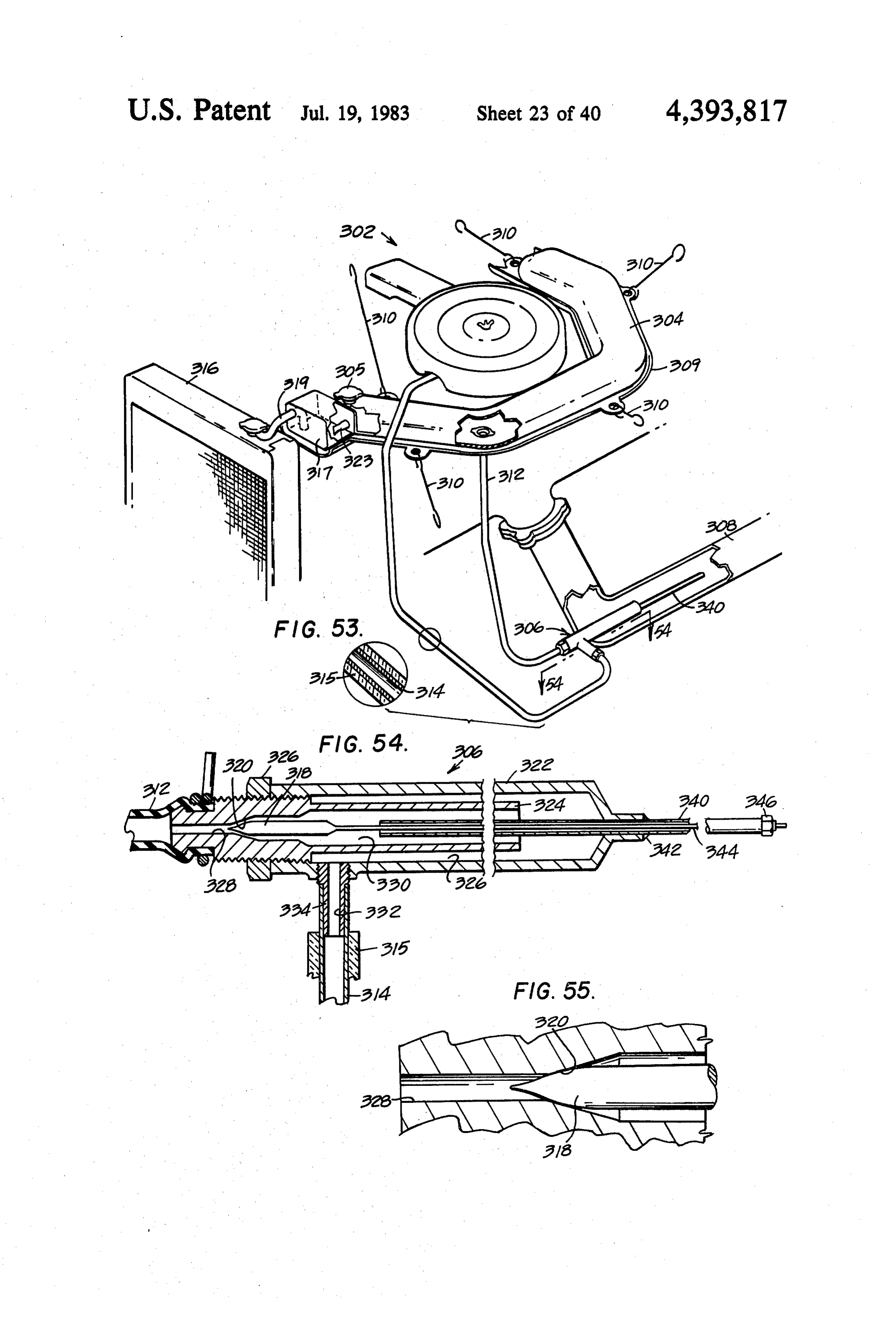
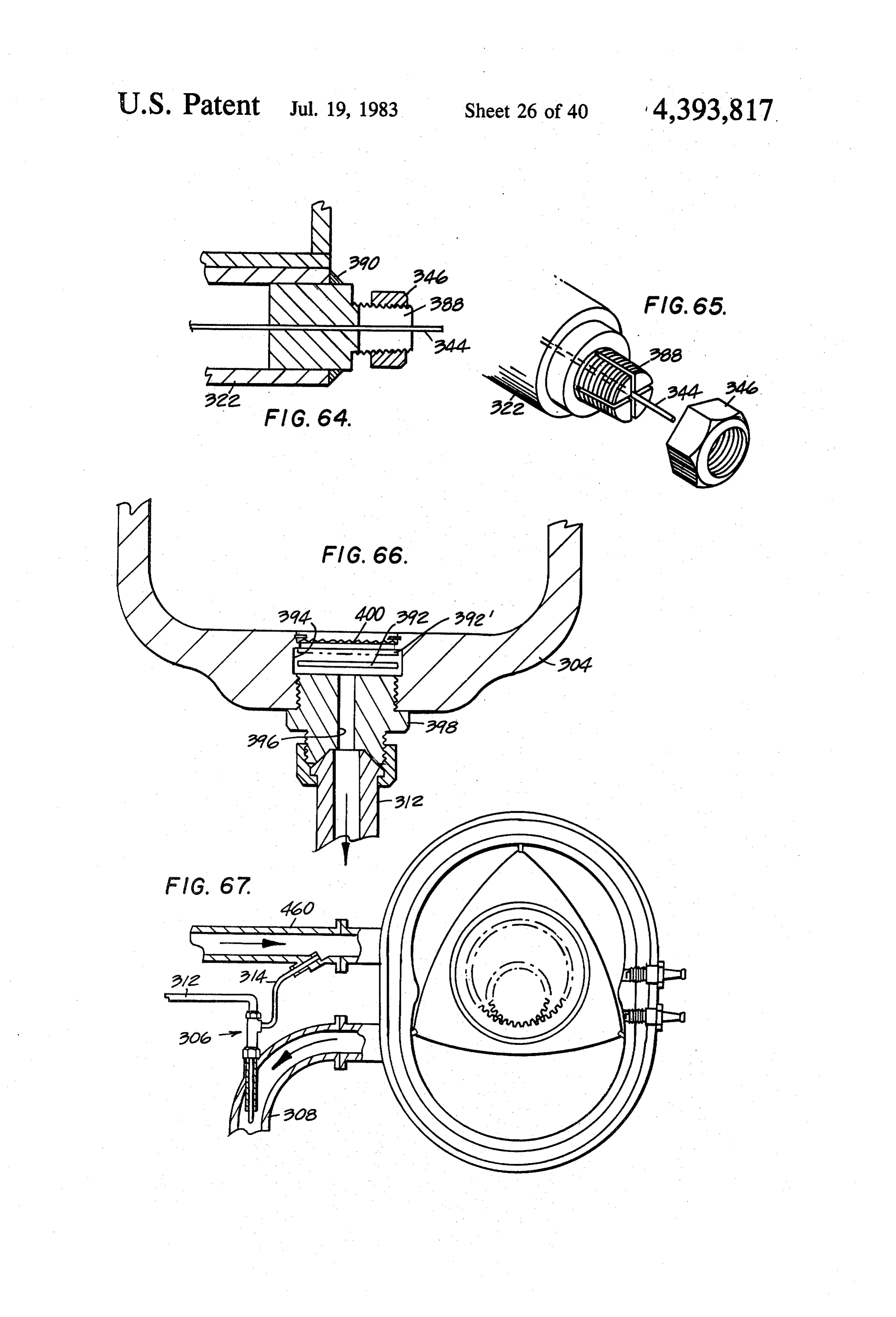
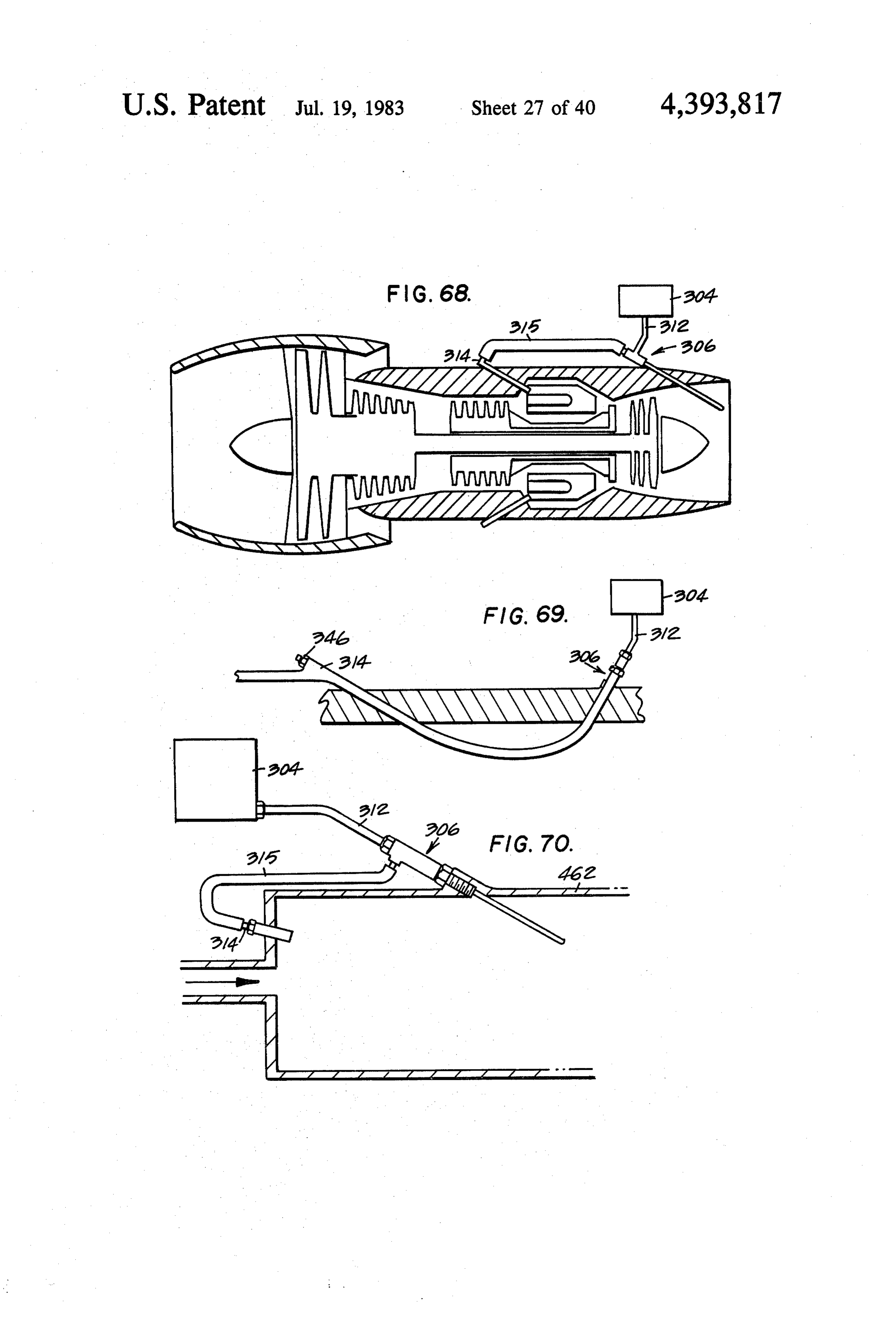
the exhaust pipe as shown in FIG. 12 for use in the FIG. 66 is a side elevation view in cross-section disclosed invention. showing a floating check valve associated with the FIG. 53 is an isometric view of another embodiment outlet conduit of the water tank for preventing back of an emission control system constructed in accor flow of water on accleration of the engine and resulting dance with the present invention. In the FIG. 53 form pressure build-up in the outlet conduit because of in of the invention the flash boiler and related conduits creased generation of steam. inject only superheated steam (without exhaust gas) into FIG. 67 is an elevation view showing how an en the engine; the water tank is mounted in the engine bodiment of a flash boiler constructed in accordance compartment above the engine to provide gravity feed; with the present invention is associated with the exhaust and the flash boiler incorporates a variable orifice flow 10 gas conduit and the air inlet conduit of a rotary engine control valve for regulating the amount of water con for injecting steam into the combustion chamber of the verted to steam in response to engine's need. rotary engine.
FIG. 54 is a cross-section view, taken along the line FIG. 68 is a side elevation view in cross-section of a and in the direction indicated by the arrows 54-54 in 15 gas turbine engine showing how a concentric tube flash FIG. 53 of the flash boiler incorporated in the FIG. 53 boiler constructed in accordance with the FIG. 54 em embodiment. bodiment of the present invention is associated with the FIG. 55 is a fragmentary enlarged view showing exhaust and the combustion chamber of a gas turbine details of construction of the variable orifice valve in engine for injecting steam into the combustion chamber corporated in the flash boiler of FIG. 54. of the gas turbine engine.
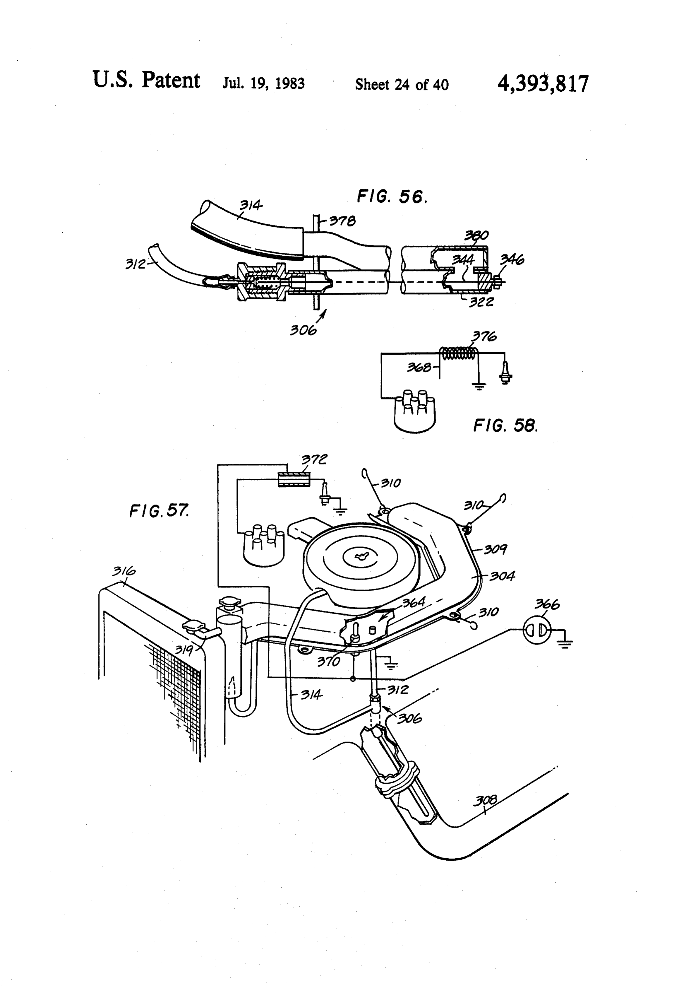
FIG. 56 is a fragmentary view, partly broken away to 20 FIG. 69 is a fragmentary view showing how a flow show details of construction, of another embodiment of through flash boiler constructed in accordance with a flash boiler and variable flow control valve con another embodiment of the present invention is associ structed in accordance with the present invention. De ated with the gas turbine engine shown in FIG. 68. tails of construction of the variable orifice flow control FIG. 70 is a side elevation view showing how a flash valve are shown in FIG. 60. 25 boiler constructed in accordance with an embodiment
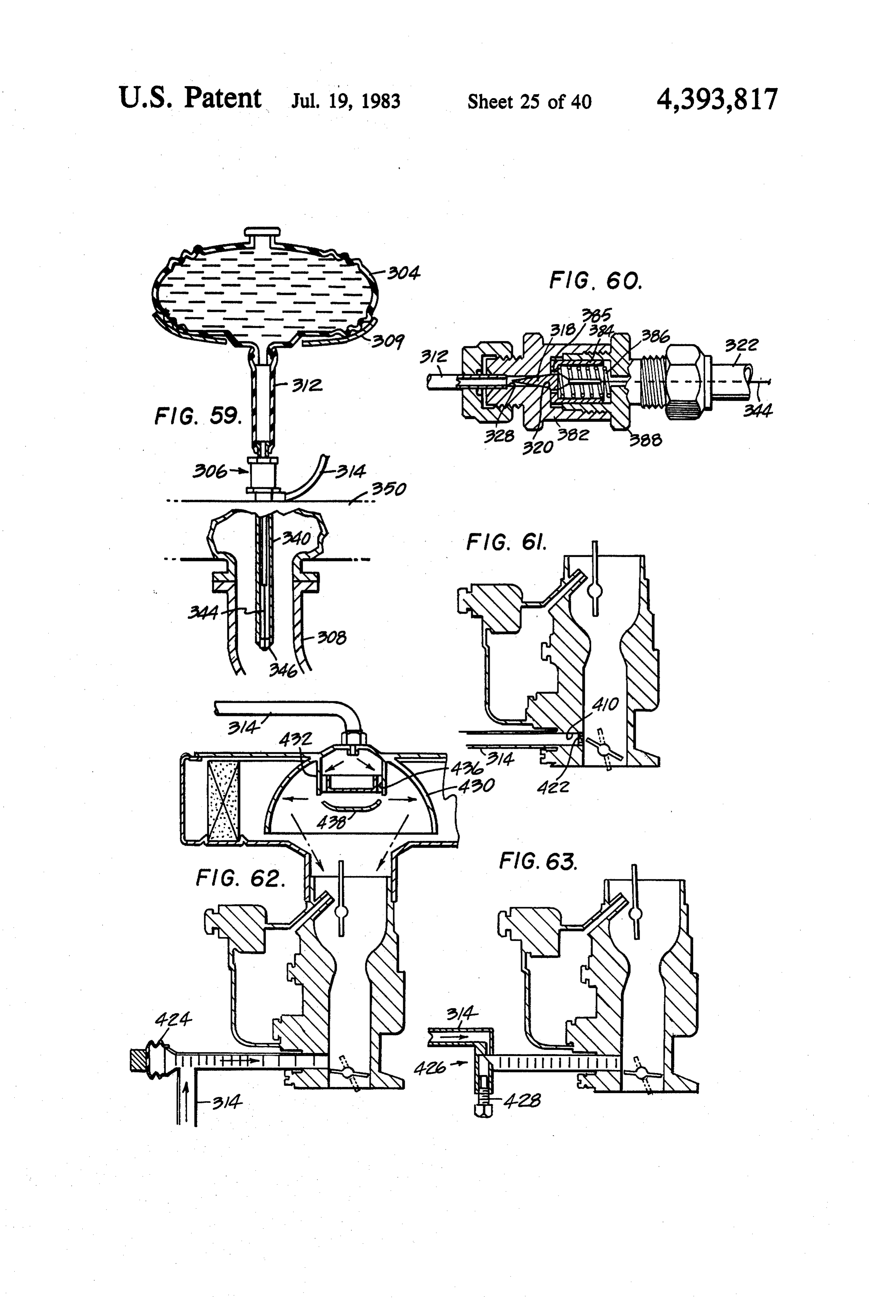
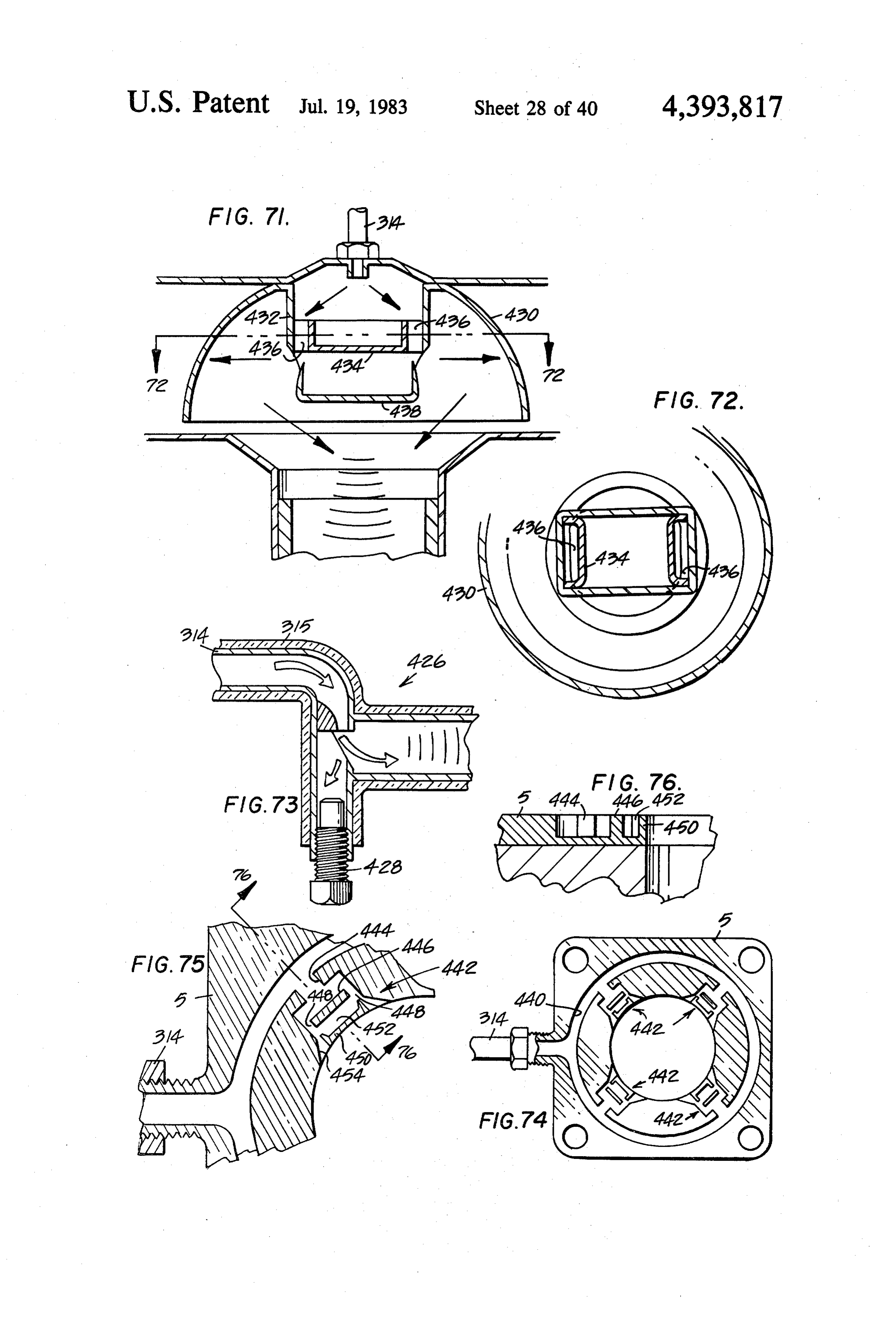
FIG. 57 is an isometric, diagrammatic view of a low of the present invention is associated with the combus water level indicating system for the embodiment tion chamber of a stationary heater (such as used for shown in FIG. 53. In FIG. 57 the pickup is a capacity power plants or a building heater) for injecting steam pickup. 30 into the combustion chamber of the heater. FIG. 58 shows an inductive pickup for the warning FIG.71 is an enlarged fragmentary view in cross-sec system shown in FIG. 57. tion of the part of an air filter for an internal combustion FIG. 59 is a fragmentary elevation view, partly bro engine which has a whistle arrangement for producing ken away to show details of construction, of a water resonant shock waves in steam injected into the engine tank and flash boiler arrangement which is particularly 35 through the air filter housing in accordance with the adapted for new car installation as part of the original embodiment of the invention shown at the top of FIG. equipment. 62.
FIG. 60 is a side elevation view, mostly in cross-sec FIG. 72 is a top plan view, in cross section taken tion, of the variable area orifice flow control valve used along the line and in the direction indicated by the in the FIG. 56 flash boiler embodiment. arrows 72-72 in FIG. 71.
FIG. 61 is an elevation view in cross-section through FIG. 73 is an enlarged view in cross section of the a carburetor showing a conduit connection to the whistle arrangement shown in FIG. 63. FIG. 73 shows ported vent of the carburetor for injecting steam into an adjustable stop for setting the frequency of the whis the engine and having an orifice for producing shock tle.
waves in resonance in the injected steam to enhance 45 FIG. 74 is a top plan view, in cross section, through intermixing of the steam, fuel, vapor and air inducted a carburetor adaptor plate showing how a series of into the engine. whistles are formed in the steam inlet conduit for pro FIG. 62 is a view like FIG. 61 showing two different ducing resonant shock waves in the steam injected and ways of injecting steam into the carburetor while pro for focusing the shock waves so produced to increase ducing resonant shock waves in the steam. FIG. 62 50 the effectiveness of the intermixing produced by the illustrates an electro mechanical resonance generator in shock waves.
the lower part of the figure for producing resonance in FIG. 75 is an enlarged fragmentary view showing a steam injected into the ported vent of the carburetor. portion of one of the whistles incorporated in the FIG. FIG. 62 shows a whistle arrangement in the air filter 74 embodiment.
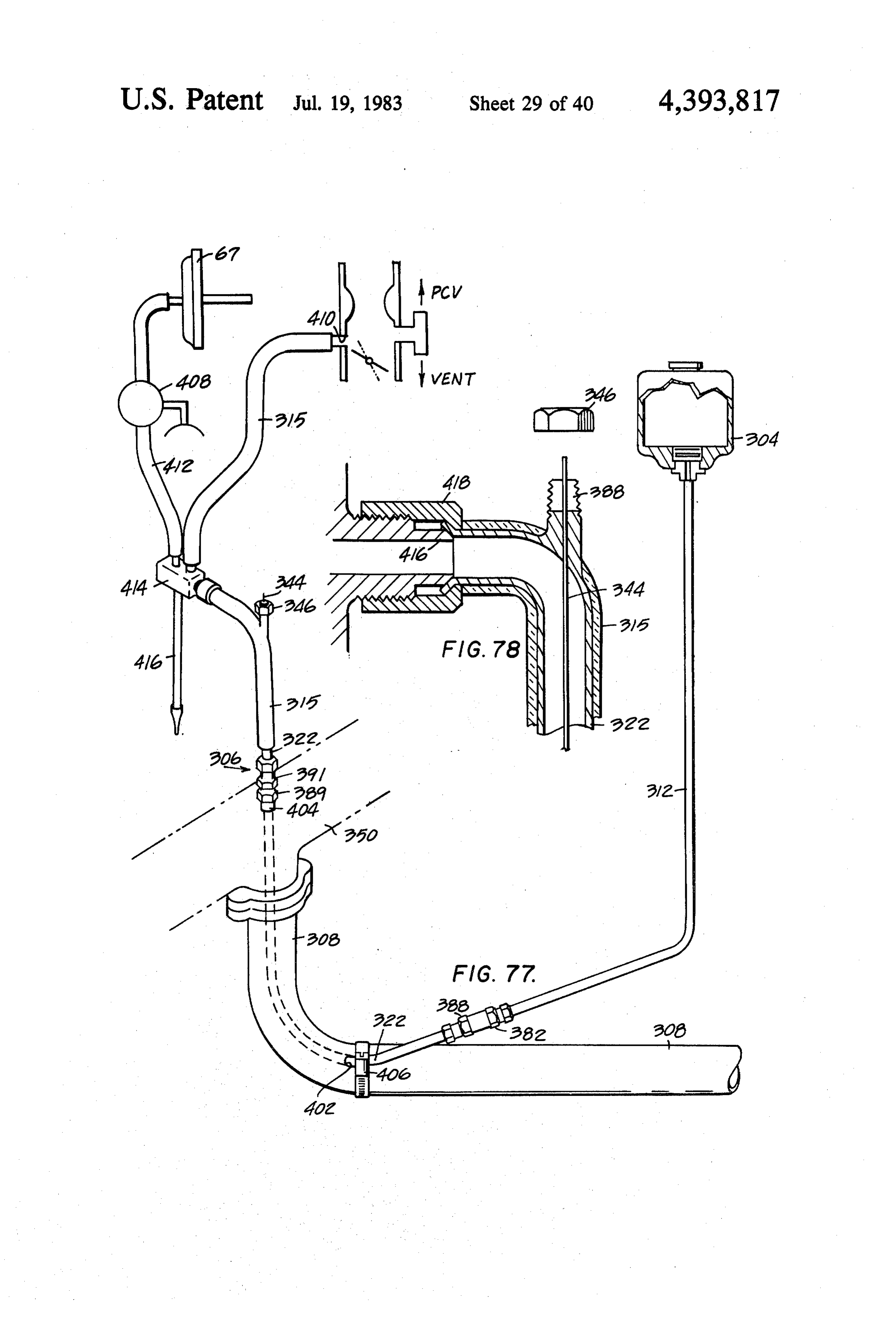
housing for producing resonance in steam injected into 55 FIG. 76 is a fragmentary side elevation view in cross the air filter housing. Further details of the whistle section taken along the line and in the direction indi arrangement are shown in FIGS. 71 and 72. cated by the arrows 76-76 in FIG. 75. FIG. 63 is a view like FIG. 61 showing a whistle FIG. 77 is an isometric, diagrammatic view showing connected in the steam inlet conduit for producing another embodiment of the flash boiler installation con shock waves in the steam injected through the ported 60 structed in accordance with the present invention. The vent. flash boiler incorporated in the FIG. 77 embodiment is FIG. 64 is a fragmentary cross-section view showing a flow through flash boiler and is fitted within a shaped a clamp arrangement for holding a wire (associated hole formed in the engine exhaust pipe. The steam pro with the movable valve element of the variable area duced by the flash boiler is conducted to the vacuum orifice flow control valve of the FIGS. 56 and 60 en 65 spark advance of the engine to provide retard of the bodiment of the flash boiler) in an adjusted position. spark advance on acceleration similar to that produced FIG. 65 is an isometric view of the clamp arrange by the exhaust retard control of FIG. 3 and the control ment shown in FIG. 64. of FIG. 12 and FIG. 45.
Page 48
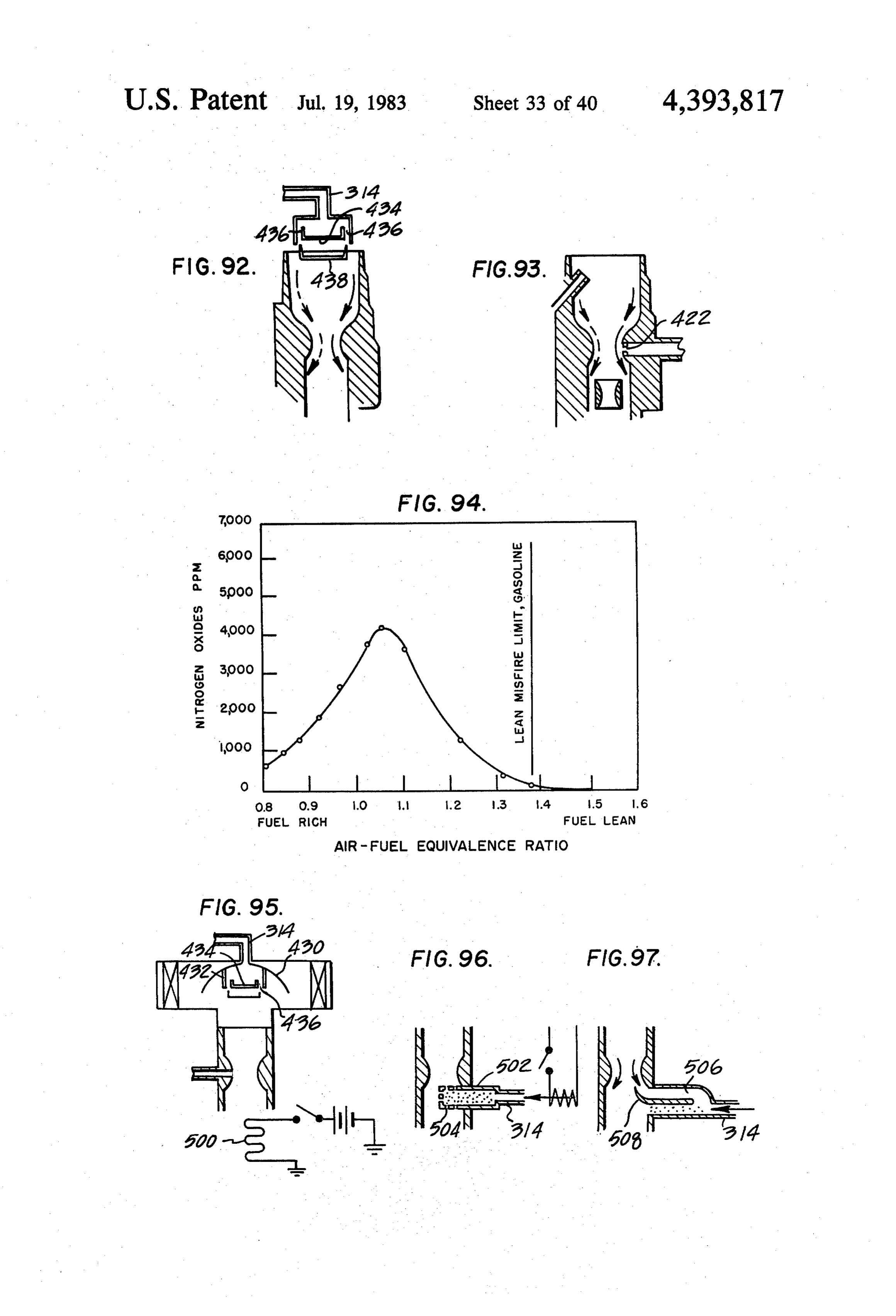
FIG. 78 is a fragmentary enlarged view showing the way below the carburetor. The arrangement shown in connection of the steam conduit to a steam-water sepa FIG. 92 involves a resonant whistle couple which rator box and showing the clamping arrangement for causes the air to flow first in one downwardly curved adjusting the control wire of the variable area orifice direction as shown by the solid arrows and then in the flow control valve of the flash boiler. The clamp ar other downwardly curved direction as shown by the rangement shown in FIG. 78 is like that shown in FIG. dashed arrows.
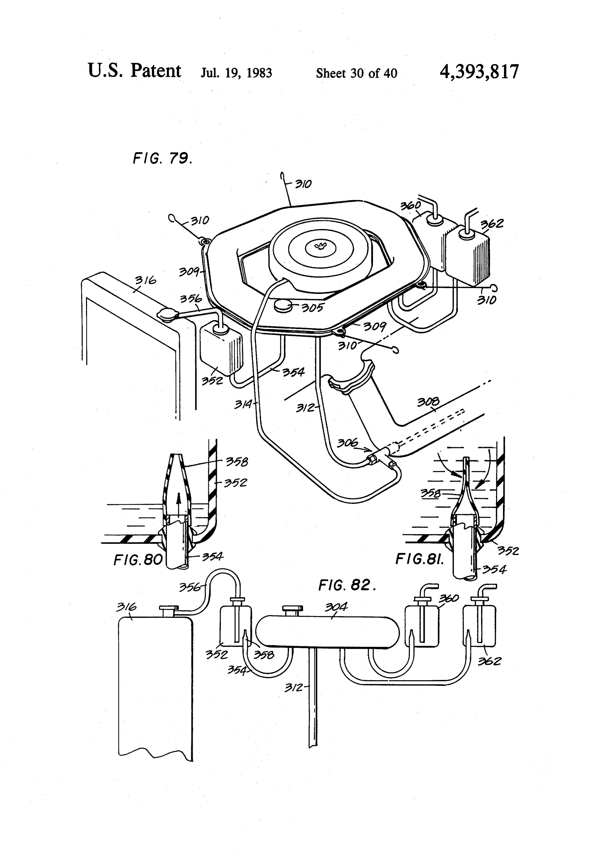
64 and FIG. 65. FIG. 93 is a diagrammatic view showing a boundary FIG. 79 is an isometric, diagrammatic view showing layer type of resonant fluidic amplifier associated with another installation of the water tank in the engine con the venturijust downstream of the throat of the carbu partment constructed in accordance with another em 10 retor. The arrangement shown in FIG. 93 uses high bodiment of the present invention. The water tank frequency high pulses to deflect the stream at the same shown in FIG. 79 is of a doughnut configuration to fit frequency as the pulses so that the stream will sweep around the air filter housing and beneath the hood back and forth across the passageway.
above the engine. In the FIG. 79 embodiment separate FIG. 94 is a graph of air fuel equivalence ratio versul water tanks are also provided to provide water for 15 nitrous oxides and shows how the nitrous oxides are radiator refill, for the windshield washer and for water drastically reduced at higher air-fuel ratios near the lean for the passenger compartment, and these separate and misfire limit line for gasoline.
additional tanks are filled through a single fill point in FIG.95 is a diagrammatic side elevation view, partly the water tank for the flash boiler and by one-way flow in cross section, showing how a catalyst is associated control valves as shown in FIGS. 80-82. 20 with the ultrasonic steam injection arrangement shown FIG. 80 is a fragmentary enlarged view showing a in FIG. 71 for increasing the hydrogen gas in the fluid one-way flow control valve in one of the additional mixture inducted into the engine.
water tanks with the flow control valve in the open FIG. 96 is a side elevation view showing how a cata position for flow from the flash boiler water tank to the lyst is mounted in a perforated structure which projects additional tank. 25 a short distance into the fuel-air mixture stream to pro FIG. 81 is a side elevation view in cross-section like vide an interaction area in which the catalyst reforms FIG. 80 but showing the one-way flow control valve hydrocarbons into hydrogen gas, carbon dioxide and closed to prevent the flow of water back from the addi water in the form of steam.
tional tank to the water supply tank for the flash boiler. F.G. 97 is a side elevation view like FIG. 96 but FIG. 82 is a side elevation view showing the connec 30 showing an alternate embodiment in which the catalyst tions between the water supply tank for the flash boiler is mounted in a channel which receives steam at one end and the additional tanks for the radiator refill, the wind and which receives the fuel-air mixture by means of a shield washers and the automobile passenger compart total pressure scoop at the other end. The fuel-air mix ent. ture and the steam react with the catalyst to increase the FIG. 83 is a side elevation view showing a flash boiler 35 hydrogen content of the mixture inducted into the en installed on the outside of the exhaust pipe in accor gine.
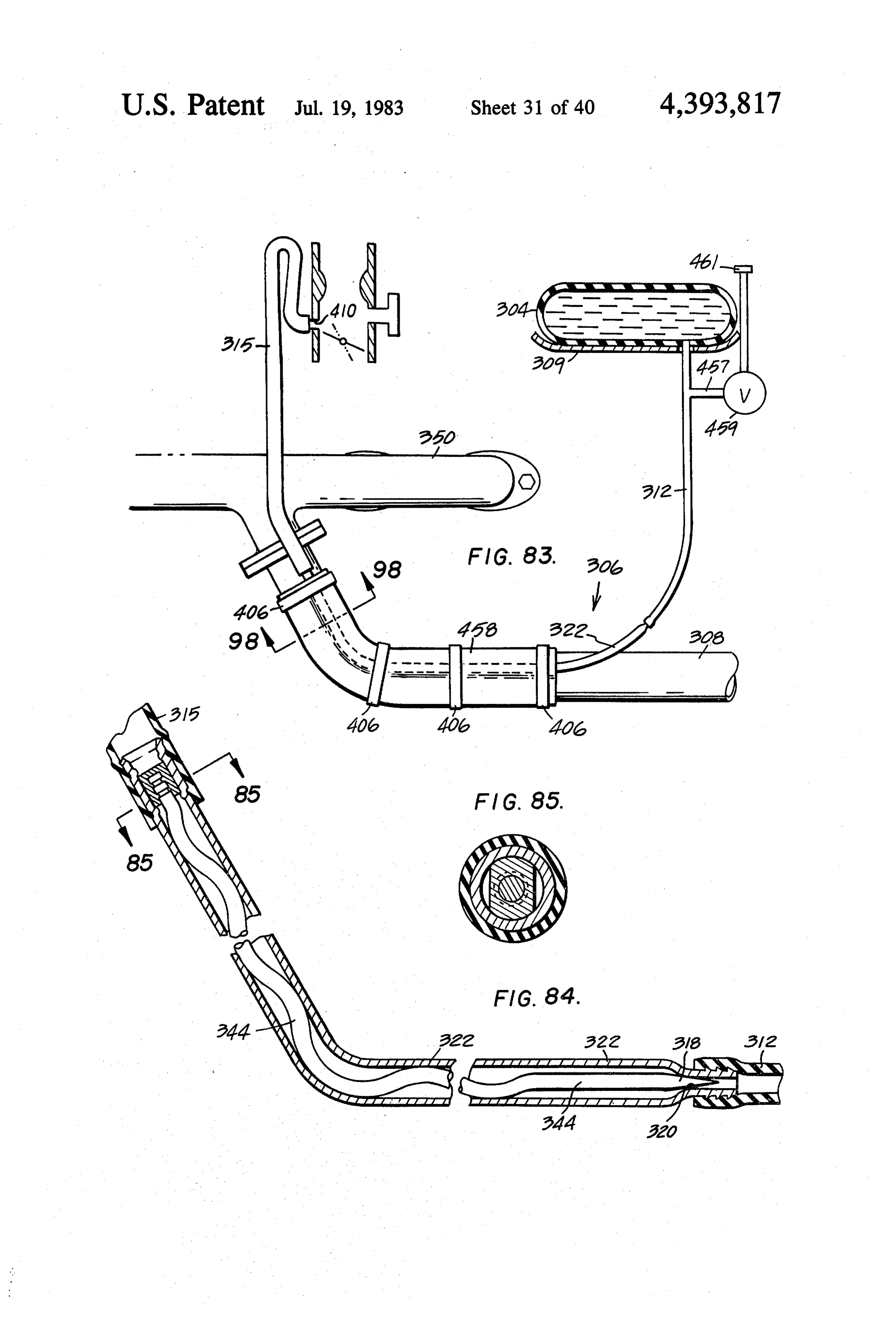
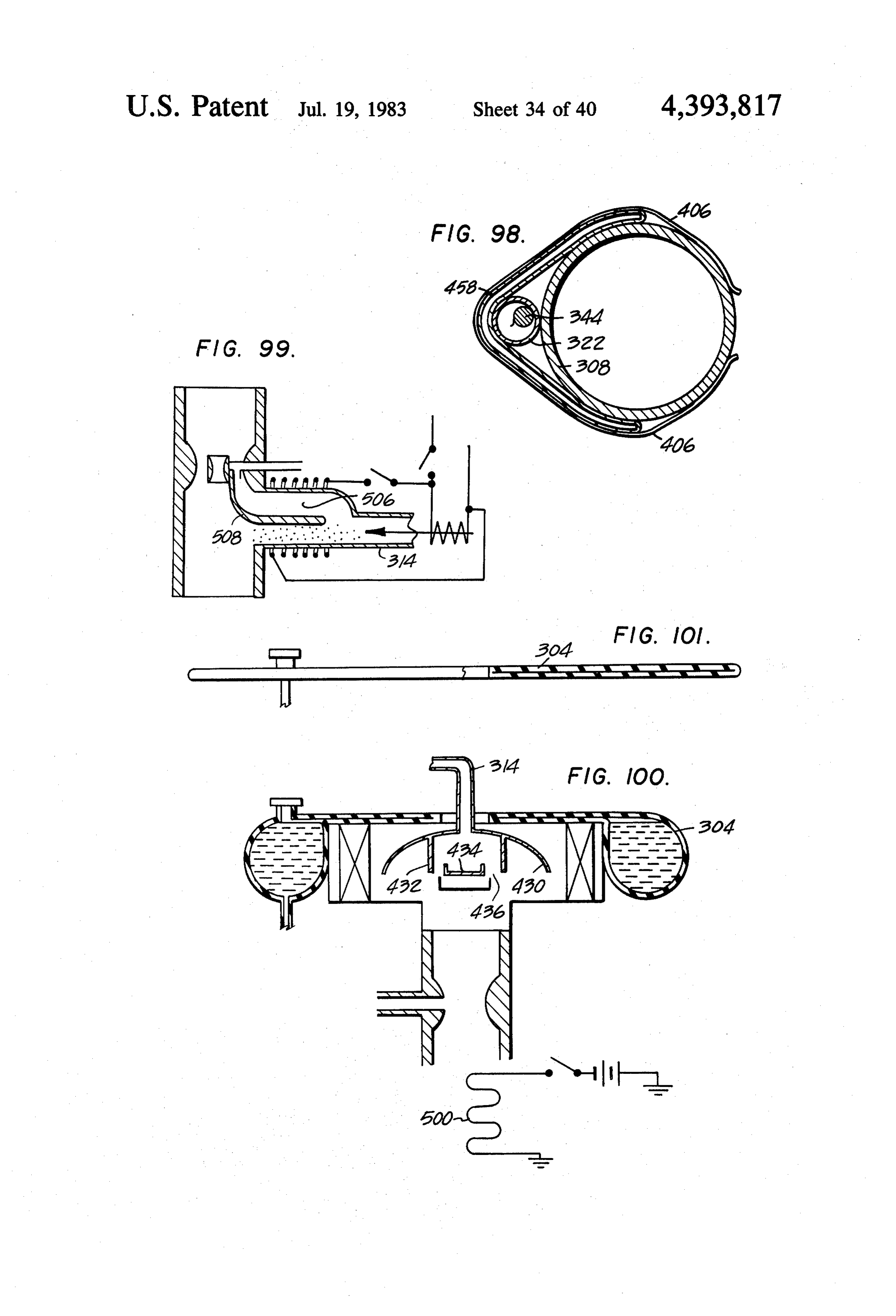
dance with another embodiment of the present inven FIG. 98 is an elevation view showing an evacuated tion. In the FIG. 83 embodiment spring clips are used to seam welded foil insulation blanket wrapped around a clamp the flash boiler to the exhaust pipe; and an evacu flash boiler on the outside of the exhaust pipe and is ated and seam welded aluminum foil blanket is clipped taken along the line and in the direction indicated by the in place about the outside of the flash boiler to maintain arrows 98-98 in FIG. 85;
the flash boiler in heat transferring contact with the FIG. 99 is a view like FIG. 97 but showing a part of exhaust pipe while permitting thermal expansion of the the carbureted fuel fed direct to the catalyst-steam reac flash boiler components. tor;
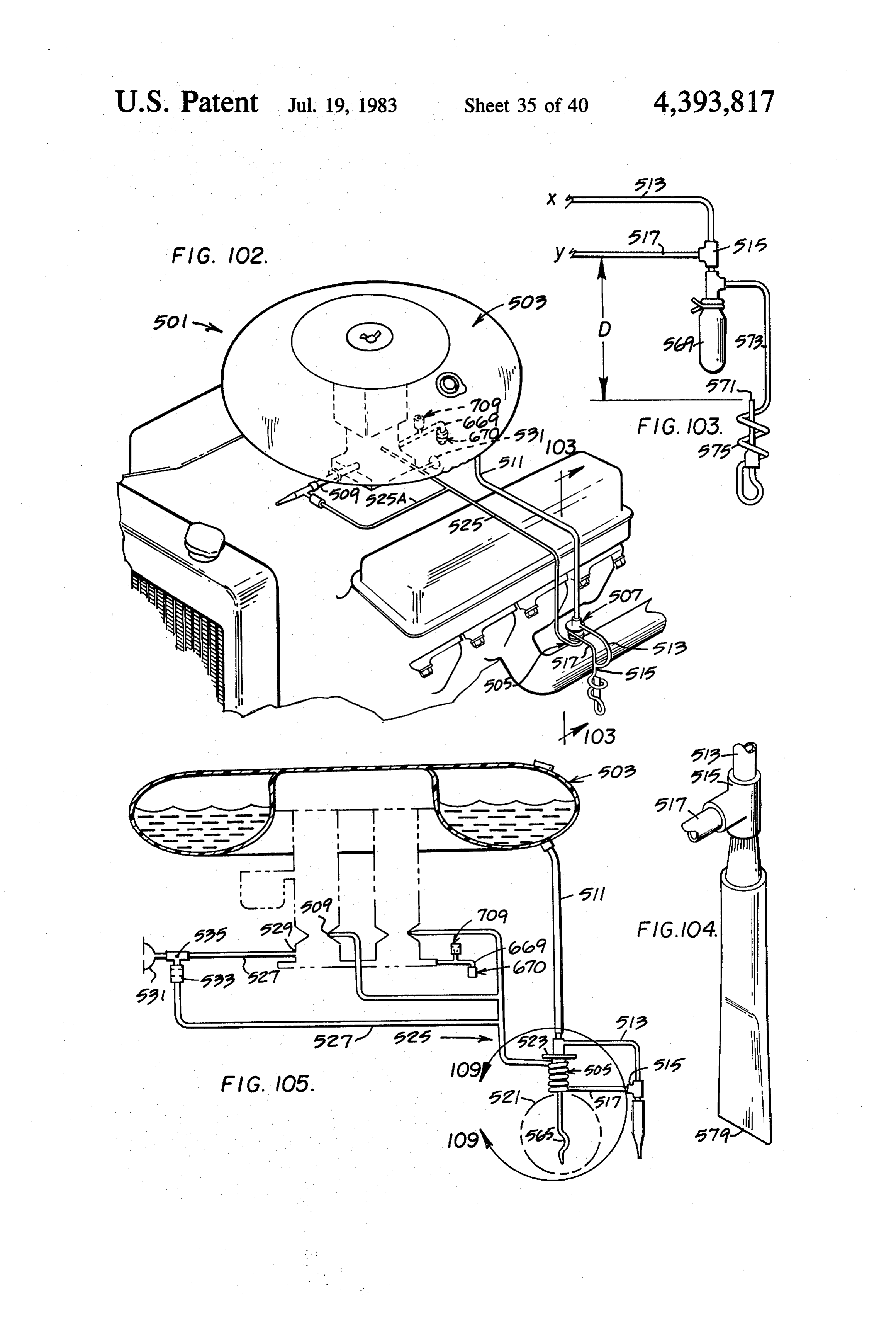
FIG. 84 is an enlarged side elevation view in cross 45 FIG. 100 is a view like FIG.95 but showing how the section of the flash boiler and shows details of the vari water tank can be supported from the air filter housing; able area orifice flow control valve and a spiral coiled FIG. 101 is an elevation view showing the tank of wire associated with the movable element of the flow FIG. 100 before it is placed on the air filter housing and control valve. The wire is spiral coiled within the flash before water is added to the tank. boiler tube to permit bending of the tube (to conform to 50 FIG. 102 is an isometric view of another embodiment the exhaust gas pipe configuration) without restricting of an emission control system constructed in accor relative movement between the control wire and the dance with the present invention. In the embodiment flash boiler tube on differential thermal expansion and shown in FIG. 102 the steam is conducted to the engine contraction of the flash boiler and without causing a through connections to both the idle adjustment screw change in the preset valve adjustment as the center of 55 of the carburetor and a connection to the ported vent of the spiral coil wire 344 remains in the tube center when the carburetor.
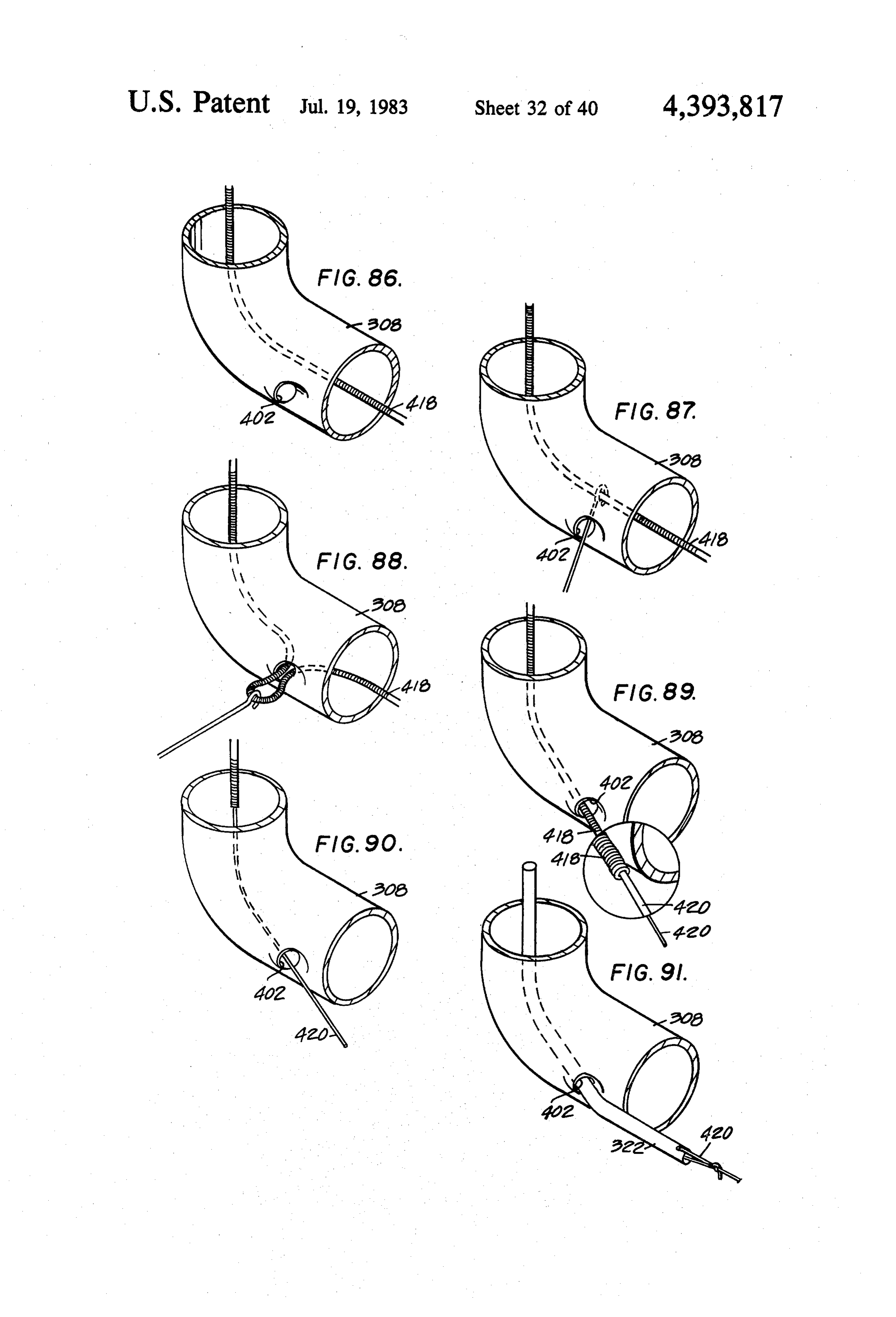
the tube is bent. FIG. 103 is an end elevation view taken generally FIG. 85 is an elevation view in cross section taken along the line and in the direction indicated by the along the line and in the direction indicated by the arrows 103-103 in FIG. 102, showing details of a flexi arrows 85-85 in FIG. 84. 60 ble wall accumulator which is resilient so as to be col FIGS. 86-91 are isometric diagrammatic views illus lapsible proportional to engine vacuum and showing trating a technique for installing the flash boiler of the details of a fluidic control drain valve which can be FIG. 77 embodiment of the present invention in the incorporated in the FIG. 102 embodiment. exhaust pipe. FIG. 104 is an isometric view showing a combined FIG. 92 is a diagrammatic view illustrating how the 65 flexible wall accumulator and fluidic control drain ultrasonic steam injection arrangement shown in detail valve (which can be used in place of the structure in FIG. 71 operates as a resonant fluidic amplifier to shown in FIG. 103) in the FIG. 102 embodiment of the produce a better distribution of the steam in the passage emission control system.
Page 49
FIG. 105 is an elevation view of the FIG. 102 em system and the added steam and air provided through bodiment (but showing a two-barreled carburetor in the inverter apparatus.
place of single barreled carburetor of FIG. 102) and FIG. 113 is a cross section view taken along the line incorporating the combined accumulator and fluidic and in the direction indicated by the arrows 113-113 in control drain valve structure of FIG. 104 rather than FIG. 12.
the structure shown in FIG. 103. FIG. 114 is a view like FIG. 112 but showing the FIG. 106 is a diagram showing the manner in which parts in the operative position assumed when the engine the vacuums within the engine manifold, at the ported is off and is not running.
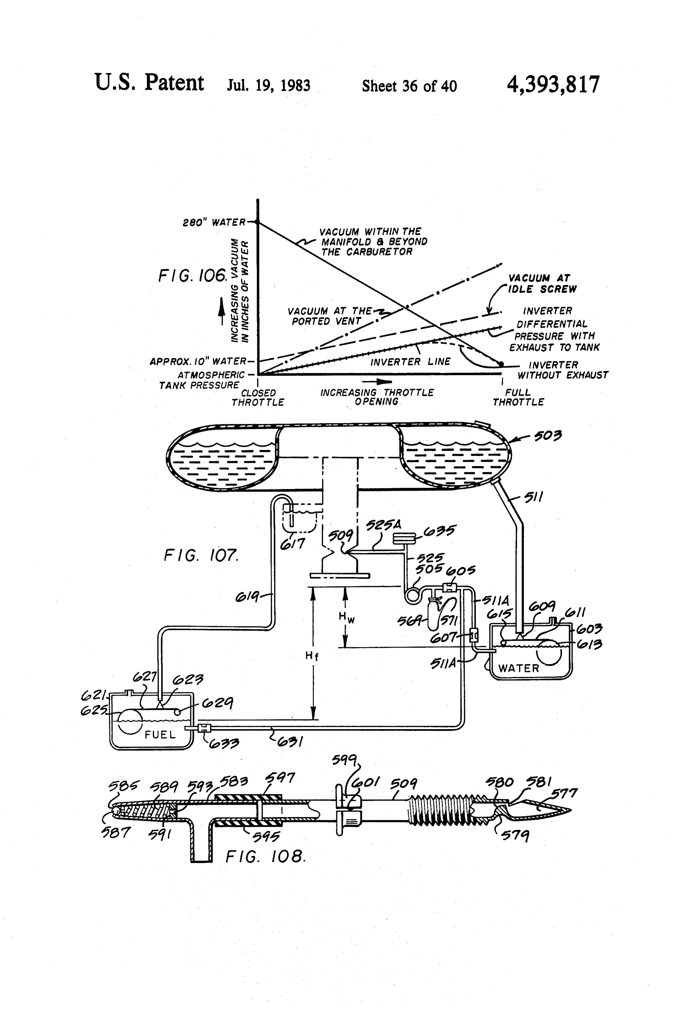
vent, at the idle screw and at the inverter (FIGS. 10 FIG. 115 is a view like FIG. 112 but showing the 112-18) respectively vary with changing throttle operative parts in the relative position assumed at part openings. throttle operation of the engine.
FIG. 107 is an elevation view like FIG. 105 but show FIG. 116 is a view like FIG. 112 but showing the ing another embodiment of the present invention in operative parts in the relative positions assumed at full which a regulated amount of fuel may be mixed with a throttle operation of the engine.
regulated amount of water and is then heated within the 15 FIG. 117 is an elevation view of another embodiment flash boiler reactor to produce precombustion reactions of an emission control system constructed in accor of these two materials before they are introduced into dance with the present invention and incorporating in the engine induction system at the idle adjustment inverter apparatus of FIG. 112 and the reactor appara tus of FIG. 10.
screw. In the embodiment shown in FIG. 107 one of the precombustion reaction products is free hydrogen 20 FIG. 118 is an elevation view of another embodiment of an emission control system constructed in accor ahead of the cylinder when either fuel is mixed with the dance with the present invention and incorporating a regulated amount of water or additives are added to the dual valve water tank. arrangement for using a decreasing vacuum FIG. 108 is a side-elevation view, partly in cross 25 field to produce an increasing vacuum effect. FIG. 119 is an elevation view in cross section through section to show details of construction, of one embodi ment of an idle adjustment screw which incorporates a aorifice valve construction which provides an increasing air bleed with decreasing vacuum of the manifold resonating chamber for producing ultrasonic injection below the carburetor. The FIG. 119 valve construction of the materials introduced into the engine induction is usable in the FIG. 102 and FIG. 105 embodiments to system through this idle adjustment screw. FIG. 108 30 provide additional lean out air on increasing throttle to also shows a variable orifice air bleed construction asso ciated with the idle adjustment screw for introducing optimize the the fuel air raatio as permitted by the system of present invention.
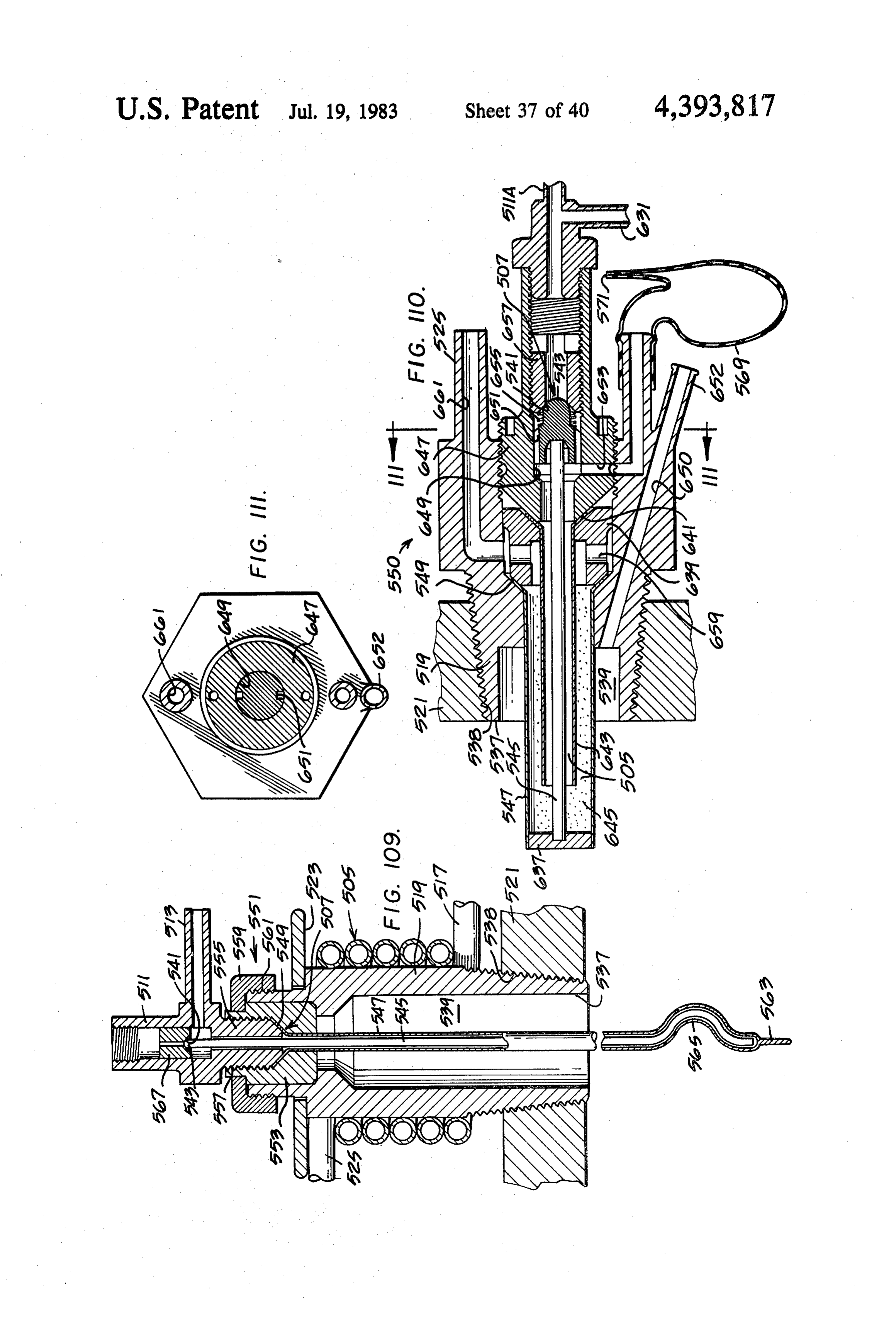
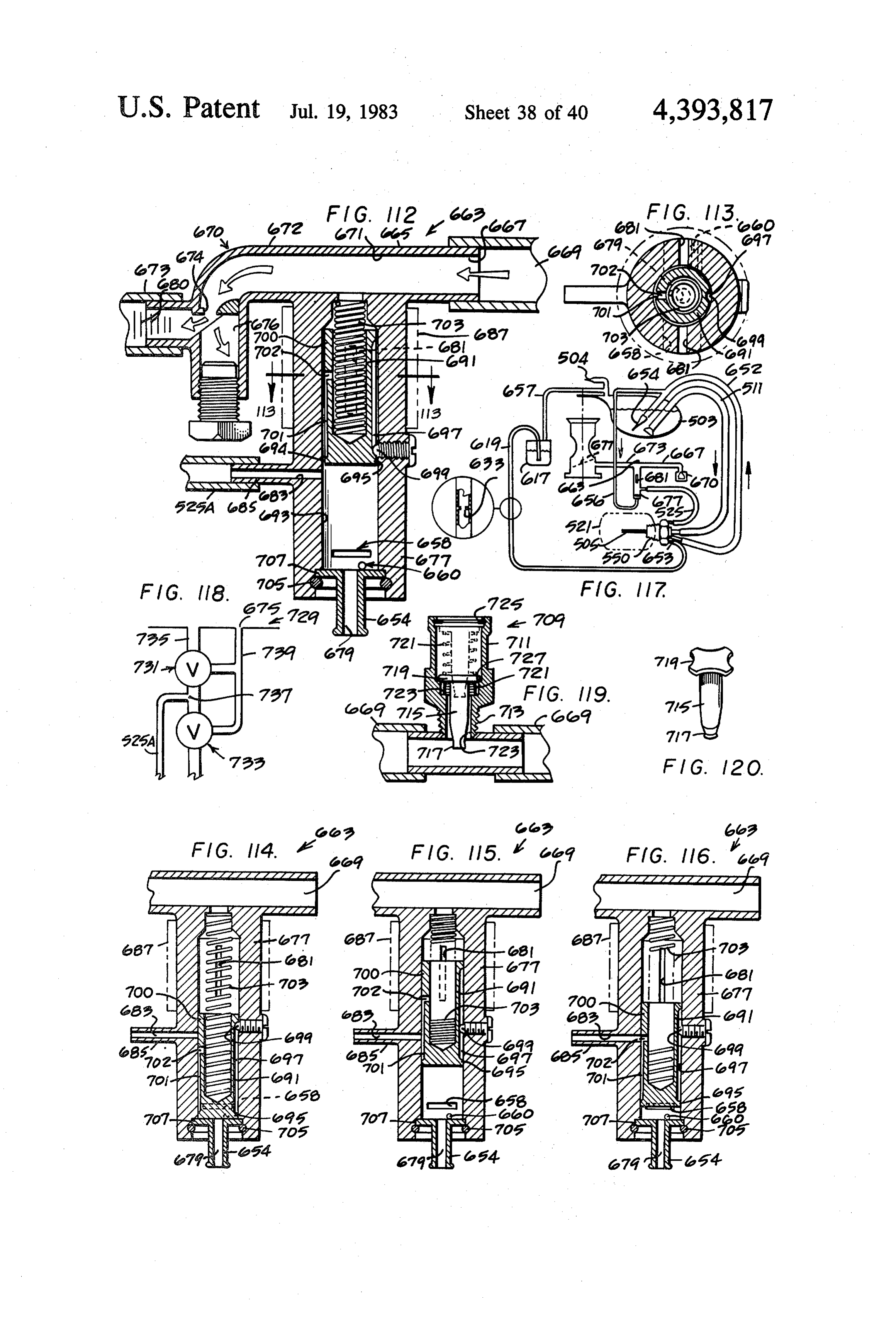
additional lean-out air if desired and in proportion to FIG. 120 is a view of the movable valve element of changing intake vacuum at the idle adjustment screw. the FIG. 119 valve construction. FIG. 109 is an elevation view in section of the flash 35 FIG, 121 is a side elevation view, in cross section, of boiler and water feed control to the flash boiler as an injector assembly constructed in accordance with shown encircled by the arrows 109-109 in FIG. 105. another embodiment of the present invention for inject FIG. 110 is an elevation view in cross section of a ing fluid at the idle screw opening of the carburetor. reactor which is particularly well adapted for incorpo FIG. 122 is a side elevation view of another embodi ration in the part of the FIG. 107 system as shown ment of an emission control system constructed in ac encircled by the arrows 110-110. The FIG. 110 reac cordance with the present invention. In the embodi tor can also be used in place of the FIG. 109 structure in ment shown in FIG. 122, water is injected into the the FIG. 102 and FIG. 105 embodiments. The reactor carburetor at a point (such as the idle adjustment screw) shown in FIG. 110 incorporates a flash boiler as an where the vacuum increases with increasing throttle integral part of the reactor and readily produces pre 45 opening and in a metered amount which is controlled by combustion reaction products because the flash boiler is both changes in engine operating temperature and exposed directly to exhaust gas temperatures in the changes in vacuum conditions. In the FIG. 122 embodi range of 1,000 to 1,800 degrees Farenheight. The reac ment a flash boiler is not utilized and water (or water tor shown in FIG. 110 is a preferred, integrated form of with additives) is injected into the engine intake without flash boiler and water and fuel feed control. Total ex 50 being converted to steam prior to injection, although in haust manifold pressure tube for use in inverter FIGS. the FIG. 122 embodiment a certain amount of heat is 112-118 is shown. added to the water.
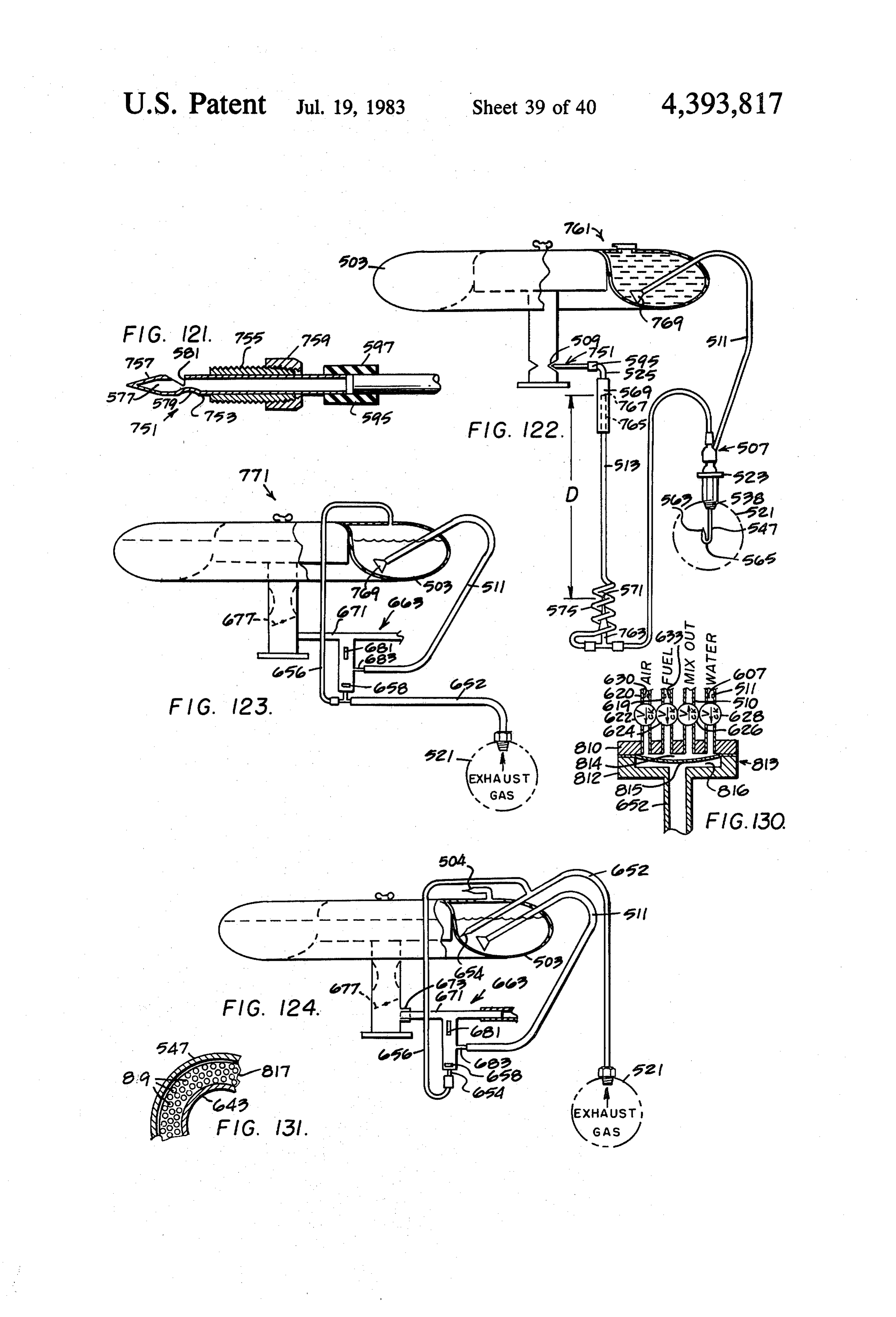
FIG. 111 is a cross sectional view taken along the line F.G. 123 is a side elevation view of another embodi and in the direction indicated by the arrows 111-111 in ment of an emission control system constructed in ac FIG. 110 and shows flow slots for permitting the me 55 cordance with the present invention. In the FIG. 123 tered feed water or combination of feed water and fuel embodiment the fluid injected into the engine is water, to flow from the metering valve to the flash boiler. Also or a solution of water plus additives, and the amount of the exhaust total pressure port is shown. fluid injected into the engine is regulated by an inverter FIG. 112 is a side elevation view in cross section of an apparatus like that shown in FIGS. 12-117 so that the inverter apparatus for converting a vacuum existing 60 amount of fluid injected is metered in response to vac below the butterfly in the carburetor from a vacuum uum in the engine induction system, as modified by that decreases with increasing engine power to a vac engine exhaust gas pressure at large throttle openings. uum which increases with increasing engine power. FIG. 124 is a view like FIG. 123 but shows an em FIG. 12 shows the inverter apparatus with the parts in bodiment of the invention in which the exhaust gas the relative positions assumed at idle condition of opera 65 pressure is rectified and supplied to the interior of the tion of the engine. FIG. 112 also shows an ultrasonic water storage tank.
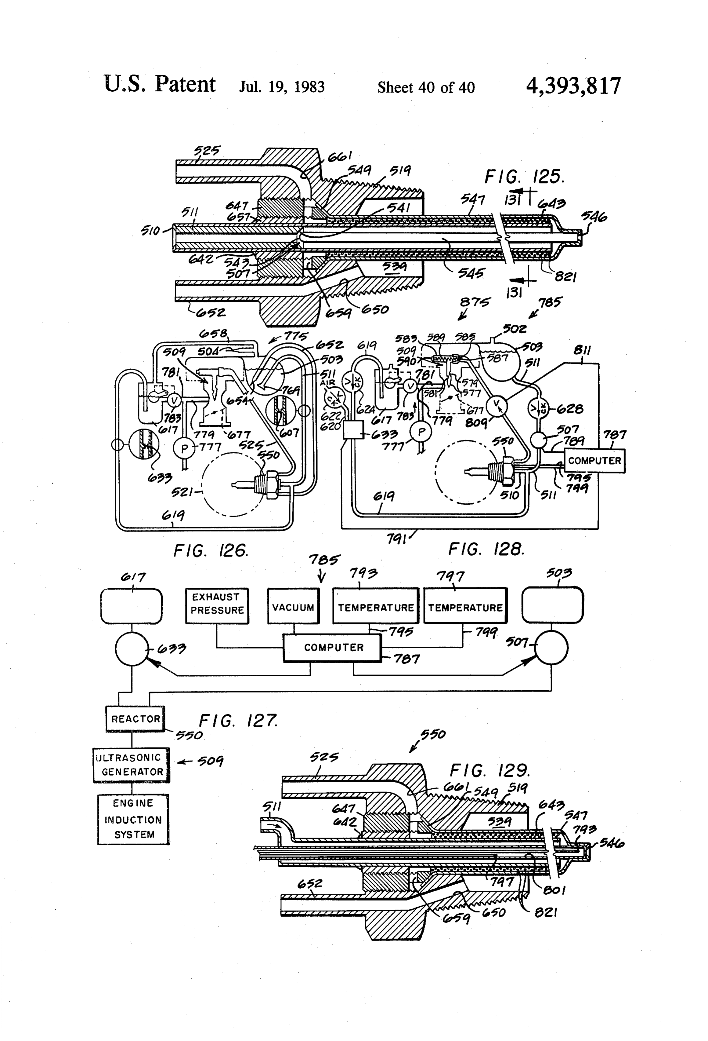
device for generating ultrasonic waves to aid in mixing FIG. 125 is a side elevation view in cross section of a the fuel, air and steam using the flow energy of the PCV heat flux valve construction which controls the flow of
Page 50
fluid in response to heat flux produced by the engine. line 2 is connected to the auto exhaust system 3 by The FIG. 125 valve assembly can be used to control the means of a special adapter gasket 4. The opposite end flow of fluid in the entirely liquid form (such as water or joins carburetor adapter plate 5. Fluid carrying line 6 water plus additives) or the FIG. 125 valve assembly transfers fluid from tank 7 through check valve 8 to the can be used to control the flow of fluid in the form of 5 flash boiler 9 joining it at 10 to its entrance into the steam or steam plus precombustion reaction products to exhaust transfer line 2. The exhaust transfer line is nor the engine, depending upon the relative size of certain mally one-half inch to five-eighths inch diameter flexi elements of the valve structure and/or the placement of ble corrugated stainless steel tubing. Flash boiler 9 may the valve in the engine exhaust system (e.g. a location be stainless steel tubing 0.93 inches outside diameter. nearer the engine to produce a greater amount of heat O The flash boiler starts at 10 and passes down the exhaust transfer or a location farther from the engine to produce transfer line to 4. Flash boiler is then formed to go a lesser amount of transfer from the exhaust gases to the forward into the exhaust manifold as shown in more fluid flow controlled by the valve). detail in FIGS. 21 and 22 and returns into adapter gas FIG. 126 is a side elevation view of another embodi ket 4 and into the exhaust transfer line and terminates at ment of an emission control system constructed in ac 15 the far end of the exhaust transfer line at 11 before cordance with the present invention. In the FIG. 126 entering adapter plate 5. Refer to FIG. 2 involving the embodiment rectified engine exhaust pressure is used to basic system of the disclosed invention in its simplest provide the fluid flow past the control orifice rather form as shown in FIG. 2. Engine vacuum below the than relying on engine vacuum for providing this fluid adapter plate 5 in the system shown in FIG. 2 typically flow as in some other embodiments of the invention. 20 will be, at idle, in the order of nineteen to twenty-one The exhaust pressurized feed system of the FIG. 126 inches of mercury vacuum. Details of adapter plate 5 embodiment permits feeding the fluid into the top of the are shown in FIG. 26. This vacuum which provides the engine intake system above the carburetor but is not force to draw the water from tank 7 through line 6, limited to feeding the fluid into the engine at this point check valve 8, and into the flash boiler starting at 10 and in the induction system. In the FIG. 126 embodiment 25 carries the water down the flash boiler tube inside the the fluid flow is controlled by heat flux and preferably exhaust transfer line steadily rising temperature gradi uses a control valve assembly like that shown in FIG. ent until it reaches 4 and goes into the very hot exhaust 125. gases of the exhaust manifold, superheating the steam FIG. 127 is a diagrammatic view of an emission con and then carrying it back through the flash boiler return trol system constructed in accordance with another 30 line still surrounded by hot exhaust gases, to keep the embodiment of the present invention and incorporating steam at a very elevated temperature as it is carried a computer for sensing a number of engine operating clear back to 11 where flash boiler 9 ends before the conditions and controlling a variable orifice valve entrance to plate 5. Exhaust transfer tube ends at 11 and which regulates the flow of aqueous fluid. The com the steam with the turbulent hot exhaust gases flows puter, as illustrated in FIG. 127, can also be used to 35 into the induction system at plate 5. There is a gradient control a second variable orifice valve for regulating of increasing temperature between 11 in exhaust trans the flow of fuel to be combined with the aqueous fluid fer line 2 because of the heat transfer to the surround in a reactor before feeding to the engine. ings through the walls of the exhaust transfer tube 2. FIG. 128 is an elevation view of a specified embodi Provision of a rising temperature gradient in the flash ment of an emission control system incorporating the boiler from the point of its entrance at 10 on down to 4 computer controlled system shown in FIG. 127. FIG. is important as it provides a great degree of stability in 128 also illustrates how the computer controlled system the flash boiler. The water entering the flash boiler at 10 of FIG. 127 is incorporated in a system similar to the is converted to steam after it has gone only a short mechanical system illustrated in FIG. 127. distance down the flash boiler 2. As the engine's power FIG. 129 is a side elevation view in cross section of a 45 is dropped, vacuum therefore increases as the throttle is reactor used in the FIG. 127 and FIG. 128 system. FIG. closed. The increased vacuum and decreased tempera 129 illustrates how two thermocouples are positioned to ture draw the water much farther down the flash boiler the reactor structure to provide a temperature differen before it converts to steam. For good operation it is tial reading which is used as one control signal for the designed so that the water point never will go past the computer controlled system shown in FIGS. 127 and 50 very high temperature of the flash boiler as it is ex 128. tended out into the hot exhaust gases of the manifold. FIG. 130 is an elevation view in cross section of a Thus, only steam will be fed into the engine from the pulse pump operated by engine exhaust pressure and flash boiler. It assures that steam will be formed in the effective to pump either water alone to a thermal con flash boiler as it enters the hot exhaust gases and this trol valve such as, for example, the FIG. 125 valve or a 55 steam so formed will stay as steam because it is sur mixture of water with fuel and air to a reactor of the rounded by hot exhaust gases of the exhaust transfer kind shown in FIGS. 126 and 128, or in FIG. 129. line all the way from 4 back to 11 and on into the plate FIG. 131 is a fragmentary enlarged view in cross 5. The use of adapter gasket 4 shown in more detail in section taken along the line and in the direction indi FIGS. 21 and 22 is very simple and convenient as a way cated by the arrows 131-131 in FIG. 125 and shows a to obtain the very high temperature exhaust gas needed monolithic type of catalyst which can be used with the and at the same time superheat the flash boiler. In FIG. FIG. 125 reactor for both lowering the temperature at 26 the exhaust transfer line is made from spiral corru which the fuel reforming process can occur and for gated flexible stainless tubing, causing rotation and tur adding heat to the process in the reactor. bulence to a high degree in the exhaust gas for excellent 65 mixing with the superheated steam, and together the
DESCRIPTION OF THE INVENTION hot turbulent exhaust gas and steam provide the energy Referring now to FIG. 1, the disclosed invention is to vaporize the gasoline and air mixture to provide shown installed in an automobile 1. Exhaust transfer excellent mixing and distribution. Approximately one
Page 51
gallon of water is consumed for every five gallons of In FIGS. 5 and 26-28 are shown variable orifice fuel. Therefore, in a large car approximately five gal valves designed to increase their area as the vacuum lons of water is desirable. Normally the water tank increases. This valve is shown in FIG. 28 and an ex should be placed at the nearest convenient point to the ploded view in FIG. 29. In these two figures, 27 is the engine, but in a modern car we find little space available housing of the variable orifice valve, and 28 is the mov near the engine and it is sometimes necessary then to able plunger that moves under the dynamic gas forces locate the water tank in a wheel underwell or in the across the valve thereby changing the effective area of trunk as shown in F.G. . The low silhouette of the the valve. 29 is the restraining spring. 30 is a retaining modern car also makes it more difficult to avoid the washer with air hole in the center and 31 is a snap ring, potential liquid lock that can occur in the car when it is 10 shown in phantom. 5 is the carburetor adapter plate. tipped (as on a hill) so that the tank level of the fluid is Attached to the plate drain hole on one side is the tub higher than the flash boiler exit adjacent to plate 5. In ing shown in phantom 32 with a drain hole at the bot this situation water will carry through the flash boiler tom 33. Inlet tube 32 is braised to washer 30 at 34.35 is system and into plate 5 and end up in the engine cylin an adjustable lean limit stop. 36 is the air intake tube. ders, causing what is called liquid lock. The water en 15 The air filter holder is 37. Limit stop 35 is adjusted to ters any open intake valve and enters the cylinder com prevent 28 from moving farther than the optimum lean bustion chamber so that when the engine is started the out point of the engine to prevent it from coming into next time, it comes up solid as it is full or partly full of the area of where combustion would be incomplete. If liquid. It is a dangerous situation, because it can cause 20 this is not provided, the system would lean out to the serious engine damage; if just the critical amount of point where the engine lost power, then would swing liquid occurs to lock a cylinder at near top dead center back to provide extra richness to cause the engine to and the engine is turning fast or starts to fire it can bend again operate and lean out again, and it tends to surge a link rod. FIG. 2 shows drain... lines 13 and 14 of one back and forth at the natural frequency of 29 and 28 as eighths inch copper tubing, for draining water away 25 an undampened spring mass system. By providing the from the engine. FIG. 26 shows raised passage 16 with stop it holds very steady at the proper ideal lean point, ledge 5 in drain groove 12 which helps to control any but when it reaches any condition where it might have water, keeping it within the drain groove 12 to let it ais momentary loss of stability and because of its leanness about to lose good combustion and is therefore losing drain through drains provided, such as tubes 13 and 4 power because it is on the very lean side of the best of FIG. 2. The wide and large entrance 16 provides for 30 power operation, the manifold pressure drops and this easy, complete flow of the exhaust gas and steam mix causes the valve body ture into the intake system. The plate holes 17, 18, 19 area abruptly reduced to by have its port cross-sectional motion of 28, by action of and 20 are the matching holes to the four barrels of the spring 29, plus the aid of gravity. This system provides carburetor above the plate. The PCV tube connection stable combustion and low emissions. With this arrange 21 connects to 22 the passage for the PCV gases. In 35 ment the engine can be set at a considerably lower idling the flash boiler partially fills as the exhaust trans fuel-air ratio and still operate stably. The valve shown fer line is cool and because the vacuum is high at idle in the ideal mounting for stability. With this arrangement,is the system shown. As we accelerate the temperatures as the car goes over a bump, as you rise, the inertial rise and the temperature of the exhaust transfer line force increases, causing conversion of the held water in that orifice,causes plunger 28 to come down and close the line to steam, providing in part the extra steam needed power to aid inrichens which the carburetor and increases the for anti-detonant, anti-preignition agent during acceler Upon going down intosmoothly the car going over the bump.
a "valley', so to speak, of a ation. The check valve is important as it prevents re bump, inertial forces acting on 28 cause it to rise, caus verse flow in the water line 6 under conditions as just ing it to lean the mixture and reduce the power, thus reviewed where steam is built up in the flash boiler. 45 cutting back on the power as the cargoes into a valley. Absence of check valve 8 would cause an emptying of These are the opposite forces which come from the car the flash boiler of residual water and during accelera striking these objects, for under the normal conditions tion the above extra steam source would be unavailable. as you strike a bump, on rise the car will be slowed The standard system, shown in FIG. in a ’69 model down momentarily, while going down into a little val Mark III, has been on test for approximately six years 50 ley, the car will be accelerated slightly. These forces are using 91 octane no lead fuel. offset by this system as above disclosed automatically. The system in FIG. 3 is similar to FIG. 2, but incor The variable orifice valves can be turned over and porates features that further extend its capabilities. Ex mounted as shown in FIGS. 5, 26, and 27, provided the haust transfer line 23 incorporates a selected fixed ori stop is used. Without the stop, if it were mounted in this fice 278 matched to the engine displacement. The flash 55 (FIG. 26) position, it would create instability in the ride boiler stops at 11, just beyond the orifice, but before the of the car in that the power forces upon striking bumps safety drain 279; alternately, a variable orifice valve to would be exactly wrong and reinforce the normal ef control exhaust flow at 24 in FIGS. 5 and 6 can be used. fects of the fore-and-aft motion (as described above) due The merits will be discussed in discussing these figures. to striking a bump. If the stop is not provided in the This orifice is designed to provide a continuous flow of 60 system regardless of which way the valve is oriented, it exhaust gas. The steam will remain hot all the way to would be unstable and together with the engine causes the plate 5. The number of flash boilers may vary from surging and as the valve first richens (closes) slightly to one to three or more. If there is more than one flash compensate for a momentary loss of power and, being boiler following exactly the same route and task, they an undampened spring mass system, it overswings as it would simply be manifolded beyond the check valve, 65 goes in the lean direction, causing the engine to be and routing of the flash boilers is shown in FIG. 7, excessively lean, causing it to again "ask' for more fuel which is a cutaway isometric view of the T-section at in relation to air, causing the valve to swing in the oppo point 26. site direction, so it swings back and forth, oscillating,
Page 52
causing engine surge. This causes very poor idling and pressure transfer line 39, which is a one-quarter to five causes very poor emissions, since it is swinging into the sixteenths inch copper tube, to water tank 7, to pressure area of poor combustion repetitively. In contrast, using this tank and thereby provide higher water feed pres the valve as shown with a stop, the system is very sta sure to the flash boilers. This is important because oth ble. The engine is set (with a fuel/air mixture ratio) and 5 erwise we find that at conditions of operation of the must be set on the lean side of best power. Thus, any system as in FIG. 2, which does not have the means of increase in leanness rather substantially drops power pressurizing the tank to increase the pressure to the and increase in richness raises power. It is necessary to flash boiler, and during operation at higher powers operate in this lean area in order to be able to control where the vacuum has diminished considerably that we emissions (providing an excess of air for complete com 10 run out of fill in our flash boiler and this results in less bustion of the fuel and minimum CO and HC) and to than the ideal amount of steam being provided to the provide a limit stop that is adjusted at idle for optimum engine and effects especially nitrous oxide formation at leanness of the engine in conjunction with the carbure higher powers, and also seriously effects the detonation tor idle adjustment settings to obtain the optimum lean limits of the engine inasmuch as we are not providing ness for low emissions at idle. While in operation and 15 one of the anti-detonants of the system, the two anti with the dynamic forces involved acting on the moving detonants being, of course, the recirculated exhaust gas, plug is set at essentially a zero force point so that as which is a very good anti-detonant, but even more engine might start to have momentary low power in one important is the hot steam, which is an exceedingly or more cylinders for any reason, the valve will quickly good anti-detonant and anti-pre-ignition agent. We need and freely move in a closed orifice direction to richen 20 to have the flash boiler run partially full so that as we the engine momentarily to avoid poor combustion, but accelerate we can get extra amount of steam at accelera the valve plug is prevented on the rebound from over tion by the sudden increase in temperature of the flash running the ideal lean set point to go to excess lean-out boiler occurring due to sudden power increase, and we and so poor combustion, as it would do in the absence of also need to have a continuous feed of steam throughout the stop. The recycling and overswing that would 25 the cruising and high power operation. This is the func occur in the absence of the stop has been shown to cause tion which the pressurized system on the tank 7 pro seriously high emissions in both idle, low cruise and vides. As soon as the engine is started, the pressure high cruise conditions. FIGS. 5 and 26 are shown as starts to build up in the tank to approximately one using two variable orifice valves, but by changing the pound, and as the power further increases to cruising dimensions of the valve involved, one variable orifice 30 operation, the pressures build up to five pounds. Pres valve could be used instead. This single valve could be sure at high powers, and in any case of acceleration, at the location of 27 or 28 or it could be in the exhaust goes right up to seven pounds. Steam pressures that are transfer line as shown in FIGS. 3 and 6, for example. accompanying this match the power, or, during acceler Alternately, the single valve could have its junction ation, exceed it, because of the sudden increase in tem to the plate at 11, or nearby. The system is much more 35 perature of the flash boiler causing extra steam to be stable if the location of the variable orifice valve for air made, converted out of the residual partially cool flash enters the system at near the end of the line of exhaust boiler suddenly converting a higher percentage of this transfer line rather than partway down the exhaust water into steam during the period of acceleration due transfer line. It is possible to obtain a vacuum at the to the sudden increase in temperature of the exhaust point 11 which is lower at idle and gradually increases gases at the flash boiler in the exhaust manifold at 4 and with power in the car. This is a desirable characteristic in the exhaust transfer line 23. Water pressure to the as it allows us to use it to obtain a better control of our flash boiler feed makes a very important change in char water supply, steam supply, and air and exhaust supply acteristics of the system, greatly smoothes out the oper in relation to engine power, since these should increase ation at higher powers, and eliminates detonation dur with engine power throughout the cruising, operating 45 ing acceleration in most all instances, when using 91 range. octane fuel in an engine designed for 100 to 101 octane Control of the exhaust flow at 24, with a variable fuel. Check valve 8 prevents the water partially filling orifice valve which is of design similar to that of the flash boiler tube 9 and that in the region normally be valve is shown in FIGS. 28 and 29. Thus, as there is an tween 10 and 4 from being forced back into tank 7. increase in differential pressure across 24, there is in 50 Referring to FIG. 25, the exhaust scoop pressure crease in exhaust flow. The system of FIG. 2 works scoop is shown as 72 inserted into a hole that had been reasonably well in cruising range; it has difficulty at drilled inside of exhaust pipe 3. The scoop 72 picks up idling both in emission control and in reasonable idling total pressure, exhaust dynamic pressure, plus static smoothness. Drivability is difficult and adjustments are pressure and transfers it through pressure line 39 to tank made to try to improve emissions in the low end. Fur 55 7. Scoop assembly 40 is readily installed by drilling a ther, at full power it suffers, for it has still full flow of hole in the side of exhaust pipe 3 and then clamping it in exhaust that decreases the volumetric efficiency of the place using clamps 41 and 42. Line 39 is a smooth tube engine and therefore it does not reach quite full power not corrugated to avoid pressure loss. In FIGS. 32 and capability of such a system, though because of the gains 33 exhaust pressure is fed through tube 39 to fittings 44 from adding steam, it does a job very close to that of the 60 and 45 through the top wall of the tank 7 through a original engine, but not as good as can be done with the pressure check valve 46 having high-frequency charac system with the addition of the variable orifice valves in teristics. Check valve 46 (in FIG. 5) is made of thermo the exhaust and in the air system as shown in FIG. 5. setting heat shrink plastic. By application of heat it is This situation is corrected, and we now have an engine shrunk over tubular extension 52. The section of check which starts easily, idles smoothly, and has very low 65 valve 46, designated by 53, is flattened, clamping sur emissions. faces applied to either side of the tube to provide a FIG. 3 shows 38, an exhaust scoop to pick up total medium pressure and applying temperature until the set pressure as shown in FIG. 25 and transfer it through point of the plastic is reached. The specific temperature
Page 53
needed varies with the particular plastic; with Teflon 268 is evacuated and the lower body chamber 271 is shrink plastic the necessary temperature is in the range vented to atmosphere by vent hole 272. Upward motion of 300 F., but with a lower temperature plastic the of diaphragm 266 moves with it, attached piston 273 temperature needed was in the order of 125-200' F. being secured by screw 274 to diaphragm 266. Piston The shrink plastic is formed in production by expanding 273 moves upward within cylinder 275, drawing water plastic under heat and then locking it in this position by from line 6 past ball 276 checkvalve. Upon full throttle irradiation, so that later on when it is heated it will acceleration the vacuum drops to essentially zero mo shrink back to its original size. It is a standard commer mentarily, then rises to about 1.5 in. Ho, and spring 270 cial product. Specifically to FIGS. 32 and 33, the fitting forces piston 273 down and the water in cylinder 275 44 is inserted through the tank plate 47 and also through 10 out exit line 277 (as flow to line 6 is blocked by 276 ball 47 there is provided a bleed valve 53, which can be check valve) and past check valve 8 and into the flash adjusted to provide desired small bleed-off of pressure boiler at 10. The flasher boiler converts this water to from the tank so that the pressure can stabilize to atmo steam and emits the steam at 11 into the engine intake. spheric pressure after shut-down of the engine. Also Thus the extra internal coolant, anti-preignition, and attached through plate 47 is a fill tube 48 and within the 15 anti-detonant is provided at the instant most needed by fill tube is provided a small vent tube, running from one the engine.
end to the other as shown by breakaway of fill tube 48 When any engine is set at optimum lean fuel air ratio so vent tube 49 can be observed. At the end of fill tube for minimum exhaust emissions and the ignition key is 48 is a spring loaded cap 50 so that during filling the turned off there is a strong tendency for the engine to spring loaded cap will open and the nozzle is inserted 20 afterfire (auto-ignition, also called dieseling). Accelera into fill tube 48, but upon completion and removal of tion pump 264 solves this problem. Since the manifold water fill nozzle, cap 50 automatically closes to assure pressure drops from an idle setting of 9" to 4 to 4" Ha. the system is always closed during operation, so that in autoignition the acceleration pump injects extra cool pressure can be maintained in the entire system. (See ant into the engine at this very moment, caused by the FIG. 1) Fill cap 50 is located inside through back wall 25 manifold pressure drop. This extra internal coolant of the fuel tank fill compartment 51. This is done in steam allows the engine to stop without auto ignition. order to assure that the service man will always refill The acceleration pump 264 is also a fluid cut off the water tank each time he fills the fuel tank. The tank valve. When the engine is off spring 270 forces piston caps and connecting tubes are such that an error in 263 against ball 276 closing off all fluid flow from line 6 tanks could not be made, filling a tank with the wrong 30 out of tank 7. In tests, pressure in line 6 even up to 50 fluid. p.s.i.g. did not cause leakage at ball 276 when engine Referring to FIG. 3, the 1969-1970 vintage cars were was off. This, then, totally solves the problem of poten designed for maximum economy and power and so tial liquid lock from leaking fluid into the engine. were equipped with high compression high spark ad This shut off valve permits the tank vent 53 to be vance engines. Therefore all development testing was 35 operated fully closed so that operating pressure up to 7 applied toward making the solution workable on even p.s.i.g. in the tank can be retained. The valve shuts off this tough environment. The system described so far in the moment the engine stops, thus providing dry flash FIG. 3 essentially solves the problems of preignition boiler at time of restart to assure steam and not water and detonation for this class car, and of course for all enters the engine. The engine easily accepts the full 7 others which are of lower spark advance and compres 40 p.s.i.g. of water pressure through the flash boilers even sion ratio. However there remained a small amount of at start up. In fact it permits remarkably slow steady idle detonation still under the most severe conditions of even at start up. This change in average pressure is what sudden full throttle at low rpm zero speed starting, and I use in the exhaust pressure control to retard the vac sometimes at transition change between gears at accel uum spark advance at the time of sudden acceleration eration at about 60-65 miles per hour. To correct this 45 when detonation is most prone to happen. Under these problem I added an additional feature 56 as shown on conditions retarding spark timing is of substantial help FIG. 3-an exhaust retard control to the vacuum spark as shown on typical engines of automotive practice advance system. In FIGS. 34-35 we see a representa today. In FIG. 20 the effect of increasing or decreasing tion of the varying cyclic exhaust pressure wave, in 34 spark advance is shown at the base and the octane num under the condition of idle, and in 35 under the condi 50 ber requirement for the engine is shown on the vertical tion of full throttle. Under modern well-designed cars, scale. Spark retard of 10" is shown to be effective in the exhaust system is tuned so the result is that during reducing the octane requirement of 5 to 7 units. A typi idle and cruising the average pressure of the exhaust is cal engine today may have a spark advance control negative, as shown in FIG. 34. However, under sudden covering around 30, so you can see the automatic re acceleration, the average pressure becomes positive, a 55 tarding of the spark advance during acceleration can be positive two-pounds gauge as shown in FIG. 35 is a very effective in eliminating detonation during this typical valve, as contrasted with a negative figure of critical period. In FIGS. 34 and 35 it shows clearly why minus one pound gauge in FIG. 34. the rectifier, or we can call it of course a fast acting An additional feature 264 (vacuum controled water check valve, 53, shown in FIGS. 32 and 33, is necessary acceleration pump and shut off valve) has been added to 60 to obtain pressure throughout the operating range in the FIG. 3 to aid further in desired automatic water and tank 7. If it were not provided during idle, we would steam feed control. Referring to FIGS. 3 and 11, on have a negative pressure in the tank instead of a positive starting the engine, vacuum immediately is present at pressure. The same would be true in cruising. It would adapter plate 5 and from there into vacuum line 265 only be at acceleration that we would have a small drawing diaphragm plate 266, attached and sealed by 65 pressure build-up of about two pounds. In contrast, by flexible diaphragm section 267, up within chamber cre using a fast acting check valve 46, we are able to obtain ated by upper body 268 and lower body 269, to over even at idle a positive pressure of one pound, and in come spring force of 270 as the upper body chamber acceleration, full throttle, a pressure of about seven
Page 54
pounds. By use of shut off valve 264 as discussed above able orifice valve 280. The curve is plotted for the we can use the full seven pounds pressure even at idle. changing conditions of idle, on up through increasing Shown in FIG, 3 at junction 54, exhaust pressure line speed to approximately 65 miles per hour, where it 55 provides pressure to control unit 56, and specifically shows the effect of a sudden full throttle acceleration, to chamber 57, and since the exhaust pressure is nega wherein the application of full throttle is faster than one tive in idle and cruise, this chamber is then below atmo second, and then upon completing the maneuver of spheric pressure. However, at sudden acceleration, full accelerating to pass, the car ends up at about 82 or 83 throttle, this chamber then becomes pressurized, and miles per hour and continues on up to 90 miles an hour causes diaphragm 58 to lift off its seat, overcoming at part throttle condition. The increase in vacuum pres spring pressure 59 and allows the exhaust pressure to 10 sure from idle to high speed cruising is to be noted. This pass through line 60 to check valve 61, shown in more is a very useful characteristic, as it allows us to have detail in FIG. 4. Exhaust pressure moves check ball 62 increase in flow of air and of pressure across the flash off of the lower seat 63 to the top seat 64, thereby cut boiler to aid in increasing the flow of water and there ting off the vacuum from line 65, allowing the full ex fore the flow of steam. The same vacuum also applies to haust pressure into line 66 to cause retard of the vacuum 15 increasing exhaust flow. It is to be noted that as we go advance control unit 67 to its full retard stop. 68 is the suddenly to full throttle the vacuum is lost and this, of thermal vacuum selector unit and 69 is the ported vac course, would cause closure of the variable orifice uum source at the carburetor. Exhaust retard control 56 valves in the exhaust line, that is, valve 24, when used, effectively provides a means to very rapidly retard the would cause closure of the variable orifice valves air spark upon going to full throttle at any power setting or 20 279 (or 27 and 28 of FIG. 5). This is a useful characteris at a passing situation at 60 miles per hour, for example. tic as it will cut off the lean-out caused by these valves If the flow restrictions of 65, 68, 69 are sufficient and being open and cut out the dilution of the exhaust by the they usually are, the control check valve 61 can be exhaust orifice valve being open, and allow full flow of eliminated. Check valve 61, however, does provide a normal air and fuel to the engine to get maximum power slightly more positive control and does keep any con 25 and acceleration, which is, of course, desired upon taminant from the exhaust gas from getting into line 65 going to full throttle. Upon returning to part throttle and control unit 68 and in port 69. The above disclosed after completing the passing move, the vacuum returns, invention has been used for nearly two years in a Conti and of course, the variable orifice valves again open up. nental Mark III '69 model with very effective results in In FIGS. 6 and 9 the variable orifice valve air 83 is improvement of combustion, improvement of efficiency 30 located about one-half way between variable orifice of engine operation using 91 octane no lead fuel without valve exhaust 24 and plate 5. The curve of pressure vs. preignition or detonation in the engine. Most cars today car operating condition expressed in speed is shown in in trying to meet as best they can the emission standards curve 72 for this location of the variable orifice valve go into auto-ignition or preignition and this has been air. Curve 73 is the normal carburetor vacuum advance fully taken care of by the disclosed invention. Tests by 35 curve. This shows a steadily increasing vacuum in an approved laboratory, show reduction of emissions going from idle to high-speed cruising, which, of such that 1974 Federal standards for hydrocarbon and course, causes the increase in vacuum spark advance. nitrous oxides have been exceeded, and it is expected Curve 74 is a plot of the exhaust controlled spark ad soon that 1975 standards will have been exceeded with vance retard with full throttle system. As is shown here, this design. In CO emissions 1980 standards have been upon reaching full throttle, there is an abrupt change exceeded. 55% improvement in mileage has been ob from a negative pressure in the exhaust to a positive tained, and a saving of approximately 5% in use of 91 pressure, from a negative pressure of minus one pound octane no lead fuel instead of premium grade fuel, giv to a positive pressure of approximately two pounds. ing a total of over 60% saving in cents per mile. Comparing this curve to the vacuum advance curve, it It is believed that 1975-1967 standards can be met by 45 is apparent why it is able to retard the spark more rap at least that time using special fluids as additives to theidly upon application of full throttle, and therefore water solution in the above disclosed system. A dilute avoid detonation at this sudden load on the engine by so solution of vinegar should be added to assure no scale rapidly retarding the spark. Curve 75 shows the tank formation in the flash boilers, or alternately other well water pressure, and how this increases, upon starting at known products used in the industry for such descaling 50 idling at about one pound, and gradually rising as the purposes. Hydrogen peroxide, H2O2, is a very strong power increases to be operating at about four pounds, oxidizing agent and can be used to further improve the and upon acceleration it goes on up to beyond to ap combustion process. Ammonia solution is useful in re proximately six pounds. Curve 76 shows how steam ducing carbon monoxide and nitrous oxide emissions. pressure increases. It follows very close to the same Alcohol can be added to the water to aid in easy vapori 55 pressure in operation to water pressure because of zation of the fuel. course there is a necessity of keeping the flash boiler full For the system shown in FIG. 3 which we have just for it to generate steam, so it is really dependent upon finished reviewing, curves of pressure p.s.i.g. (pounds the water pressure. At the time of acceleration, some of per square inch gauge) plus and minus in relation to the the stored water in the flash boiler is suddenly con zero line, which would be atmospheric pressure, are verted to extra steam and that causes a further rise in plotted against car speed in miles per hour for various steam pressure over that of the water pressure. In the important points in the system. Their review will aid in upper portion of FIG. 36 the differential pressure in our understanding of the system. This is plotted in the p.s. i. (pounds per square inch) is plotted. Curve 77 is the lower part of FIG. 36. The lowest curve, 71, is a plot of differential pressure controlling the variable orifice the pressure which is a vacuum below atmospheric 65 valve exhaust. Curve 78 is the curve of differential pressure at the adapter plate below the carburetor. It is pressure operating the variable orifice valve air when in therefore the pressure at point 11, which is the end of the location of 83 on FIG. 9. FIG. 79 is the curve of a the flash boilers. It is the vacuum pressure across vari variable orifice valve air with its outlet close to the
Page 55
carburetor adapter such as a location at approximately connecting rod 103 drives the water pump piston 104 , the end of the flash boilers, or a location at 27 or 28 which contains a cavity 105 and a check valve in the of FIG. 5; as noted, there is less change in pressure form of a ball 106, which seals as the piston rises verti across the variable orifice valve air as it is located near cally, and lifts off its seat as the piston goes down, per the plate with change in operating condition between mitting water flow through cavity 107. Upon the next idle and high speed cruising, for example. However, cycle upward, water is pumped out of line 83. At the upon going to full throttle the valve in either location same time the lower part of the water pump cylinder is abruptly goes closed. FIG. 80 is a curve showing the filled from line 6 by lifting ball check valve 108 off its differential pressure across the water feed to the flash seat. The water pump is therefore double-acting in that boilers. As noted, as we increase from idling with a 10 it fills the lower part of the pump at the same time that pressure of approximately six pounds differential pres it empties the top and on the downstroke, it transfers the sure, it gradually increases to approximately 13 to 14 fluid from below the piston to above the piston. 99 is pounds at high speed cruising. However, as we go to the slide valve housing and 110 is the control slide valve full throttle, we lose differential pressure as shown by for controlling the operation of the steam piston. It is the curve 80. This is because we lose the assistance of a 15 pneumatically operated by steam pressure. Steam feed vacuum upon going to full throttle. As the pressure at line 86 branches at point 111 to lines 112, 113, and 114. 11, the end of the flash boiler, becomes atmospheric, Line 113 branches at 115 to enter the slide valve control very nearly, curve 81 is the differential pressure of the at 116 and at 17. Line 12 enters the end of slide valve steam feed. It is the same as the water curve up to the cylinder at 118 and at the opposite end of the cylinder point of going to full throttle, at which time it has less 20 line 114 enters at point 19. Port 120 at the base of the dip than the water feed line, but nevertheless is a dip. steam cylinder is connected to line 21, which has a This dip in the steam feed pressure at the time when it branch point 122 with a branch line 123 that enters port is needed the most is unfortunate. We really would like 124 of slide control valve assembly, said port 124 being to have a curve like curve 82 in which at the point of in line with previously mentioned port 116. Line 121 going to full throttle, pressure would abruptly increase. 25 also enters port 25 as shown. Slide valve 10 has three This is substantially accomplished by acceleration pump circular grooves as ports, one at the top is 126. The one 264. Other means of accomplishing this will now be at the center, which is longer, is 27 and the bottom one, discussed in discussing some of the further figures. which is symmetrical with the top 126 port, is port 28. In FIG. 5 the basic system is the same as FIG. 3. Connecting rod 103 has two annular grooved ports. However, a steam driven boost pump 84 is provided to 30 The upper one is 129 and the lower one is 130. Cylinder boost the pressure of the feed water to the flash boiler or housings 98 has drilled cross ports 131, which tube 112 boilers. Use of steam pressure from one of the flash connects to on each side, and drilled port 132, which boilers as the driving force in the pump to boost the tubes 114 match with on either side. Port 131 and annu water feed pressure to the flash boilers, is ideal as it will lar groove 129 are designed so that they will match then boost the feed water pressure in a power function 35 when the steam piston is at the top of its travel. Like multiple of the temperature the flash boiler is exposed wise, drilled port 132 is matched with position designed to. This is then related to the real need for a boosted for annular port 130 so that they will match when the steam feed pressure. It relates to the real need of further steam piston is at the bottom of its travel. 33 is the steam pressure. The steam pump then takes one of the steam piston head and 134 is the water piston head, flash boiler's outputs at 85 and through line 36 applies it containing check valve 108 and input line 6. As now to the driving turbine or pump, according to which is shown in FIG. 39, the steam piston is at the upper end used. See FIGS. 37 and 38 for the turbine system, and of its travel. 135 is a port at the top of the steam piston see FIG. 39 for the pump system. Now referring to connected to the line 136 which has a branch line con FIGS. 37 and 38, in FIG. 37, 84 is a steam pump useful ing off at line 137 to the branch line 138 which makes a in this invention. 89 is a steam turbine driving 90, a 45 port entrance into slide valve housing at 139. Line 136 turbine pump to boost pressure to the feed water. 91 is continues and makes an additional entrance at the bot a steam rotor like a pelton wheel, mounted on bearings tom of slide valve housing at port 140, which is in line 92 and 93 at either side. Steam jet orifice at 94 drives directly, of port 117 on the opposite side of the housing, across the top of the turbine wheel, causing its rotation and also in line with the annular port of slide valve, port and the steam exits at 95 through tube 87. Shaft 95 is 50 128 when said slide valve is at the bottom of its travel. driven by the steam turbine and is sealed by Teflon seal Port 141, in the center of the slide valve housing, is 96 and drives water turbine 97. As shown, the water joined to steam exit tube 87. This said port 141 is located turbine is conical in shape, having four vanes. The in the center of the slide valve housing, and port 27, water feed into the water turbine is 6 and the out pres which is in the center of the slide valve itself, is de sure boost pressure of the turbine is 88. As shown in 55 signed with proper width so that it includes the port 141 FIG. 5, the output is fed as 267 into the acceleration and port 125 when it is at the lower end of its travel, and pump and shut off valve 264 and then to the flash boilers includes port 141 and port 139 when it is at the upper by a manifold at 10. In the turbine the rotor is preferably end of its travel. Also when slide valve is at the upper stainless steel, bearings can be ball bearings, but should end of its travel, port 126 lines up with port 124 and 16. be stainless steel, or they could be Teflon bearings. The 60 As a consequence, port 129 and port 13 line up, permit body could be stainless steel or nylon. ting steam pressure to pass through line 12 to port Now referring to FIG. 39: as shown, housing 98 has entrance 118 to the top of the cylinder of the control an upper cylindrical cavity 99 and a lower cylindrical slide valve 110 forcing said slide valve 110 to the bot cavity of smaller cross-sectional area 100.99 is the driv tom of its travel.
ing steam piston, double-acting, and 100 is the driven 65 The slide valve 110 now having been forced to the water piston, double-acting. 101 is the steam piston, 102 bottom of its travel has aligned port 28 with ports 17 is the spring cushion, the end of the piston travel. 103 is and 140 so that now steam pressure coming in from 186, a link rod threaded into the piston 101 for assembly. The passes through lines 15 and will then pass through said
Page 56
ports and through line 136 to the top of the cylinder to the start-up period, which is a condition of the worst one port 135 and put pressure upon the top of the cylin emissions, there is a long period in which the excessive der, forcing it down. At the same time the bottom of the richness of automatic choke is causing serious emis cylinder is vented through port 120, line 121 to port 125 sions. With the disclosed invention, the energy of the and through the annular port 127 of the slide valve, to 5 recycled exhaust gas, and the super-heated steam con port 141 through line 87, which is the exit line. Upon the bined and with their considerable turbulence and heat steam piston reaching the bottom of its travel, port 130 energy very quickly vaporize the fuel-air actual mix will line up with a port 132. This, then, allows steam ture; since the flash boiler is directly in the exhaust pressure from 186 to pass through line 114, port 132, stream it is only a matter of seconds until it is forming port 130, to the line through 119 to the lower end of 10 steam. And so the whole system operates very quickly slide valve 110, forcing said slide valve upward to the to heat the induction system ingredients to provide end of its travel. Upon reaching the upper end of its good vaporization. Except for the starting of the engine travel, slide valve ports 126 will line up with port 116 automatic choke would not be needed at all with the and 124, therefore steam will now travel through line system disclosed. However, with the arrangement just 115 and through port 116, annular port 126, port 124, 15 described where the exit of the steam from the steam through line 121 to port 120 to put pressure on the pump, or in the absence of a steam pump a flash boiler bottom of the steam piston and force it to the top of its steam content would be fed into the engine through the travel. At the same time, there will be an exit passage automatic choke control thermostatic unit 143. Because for the steam which is being exited from the top of the of the high specific heat and the high temperature of the piston through line 136through port 139 to annular port 20 steam, this very quickly heats the bimetal element and 127, which is not therealigned, back through port 141 removes the effect of the automatic choke from the and out exit 87. Thus, the steam piston continuously system. This is done within a few seconds to thirty cycles back and forth, causing pneumatically operation seconds, rather than in minutes. This further greatly of the slide valve to cause proper changes in the valve works to eliminate unwanted exhaust emissions. ports to permit this operation. In doing so it cyclically 25 Referring again to FIG. 5, 144 is the ignition switch, pumps water with the piston 104, as previously dis at present shown in the ignition on position, 145 is the closed. The pressure pumped with the water is at the primary ignition coil, 146 is the secondary ignition coil, boost pressure proportional to the ratio of the area of 147 is the breaker point condenser, and 148 is the the steam piston divided by the area of the water piston. breaker point of the ignition system. 150 and 150' are This allows substantial boost in fluid pressure if desired. 30 spark gaps provided in each of the two exhaust mani For instance, it could be as much as 50:1 if desired. At folds at the exhaust manifold gasket as it joins the ex the bottom of water piston 104 is an attached spring 142, haust pipe. The spark gaps are part of a sandwich ther when steam pressure is off, the slide valve and the steam mal catalytic reactor that fits at the gasket point into the piston will both go to the bottom of their travel, and the exhaust pipe just below the exhaust manifold. The spark steam piston and its link rod and water piston will rest 35 gaps assure continuous ignition even at starting of any upon check valve ball 108 at the bottom of the travel, by. unburned combustibles in the exhaust system. The spark way of spring 142. This would be designed to require at gaps are part of a small catalytic thermal reactor that least two pounds per square inch pressure on line 6 to fits into the gasket space in place of the gasket, between force water through check valve 108 under this condi the exhaust manifold and the exhaust pipe header. As tion, and therefore act as a block against liquid lock in shown, 150 fits with 151 into 152 and 150' fits with 151' the system should the water tank level be above the into 152', 151 and 151' being the thermal catalytic reac flash boiler outlet 11 due to the car being out of level. tors. This is shown in more detail in FIG. 51. Referring This could make the shut off valve in 264 not required. to FIG. 51, exhaust pipe 3, partly cut away, is shown In FIG. 5, the exit line of the steam pump, be it tur with the header flange 152. Above this is shown the bine or piston, is 87, and will be fed back into the induc 45 gasket adapter 150, which is in two halves. In construc tion system through the inlet port of the bimetal control tion 156 and 157. These are of high-temperature insulat element of the automatic choke control used as standard ing material, such as filled asbestos. The gasket 150 is equipment in most of the American cars. The input of arranged to provide a slight venturii action and there this unit 143 is normally from a hot air bleed, to take hot fore creates a suction at the air gap 158, so that air 159 air from the intake manifold, and the output is at a vac 50 can flow inward, so that air can be added to any com uum point in the induction system of the carburetor. bustibles in the exhaust to create complete combustion. Because of the massiveness of the engine and induction Flash boiler line 9 is shown in the exhaust stream. Ther system, it takes considerable time to heat this up to the mal catalytic reactor 151 is shown supported in conical point of causing the bimetal unit to operate and elimi form by the gasket. It is made of woven very high tem nate the effects of the enrichment caused by the auto 55 perature fibers such as coated graphite or silicon car matic choke unit. In order to start the engine it is neces bide-carbon fibers. These would be vapor or solution sary to have the vapor air ratio within the combustible dipped with a thin platinum coating to make them cata zone. If it is cold at starting, it is necessary to use a rich lytic in reaction, because they are very small in mass, mixture of fuel air ratio in order to get sufficient vapor made up of many many fine fibers. This woven net-like air ratio to start the engine. For instance, in FIG. 21 60 structure will act like a flame-holder and still not be an with a typical summer fuel, at 20 F. it requires 4:1 appreciable restriction to the flow of exhaust gases. fuel-air ratio to get 16:1 vapor air ratio. However, as the Granular catalyst can be placed in the bottom of the engine warms up, the ratio rapidly changes, and very flame holder to further augment the catalytic reaction. soon it is excessively rich in vapor air ratio. The auto Because of the primary cleanup of emissions being done matic bimetal control in the choke assembly is designed 65 by the primary system, already described, the remaining to match the thermal characteristics of the engine to unconverted emissions are relatively small in volume, slowly heat up as the engine slowly heats up to keep it and therefore a small efficient catalytic thermal reactor within the combustible range. This means that during located in the area where the exhaust gases are still very
Page 57
hot, provides a very efficient way to finish the clean-up ble time. If switch 175 is left open and switch 170 is to meet the standards such as 1980 standards. In 51, 160 closed and rheostat 171 can be used to vary the output is the exhaust manifold flange. of the electric pump movable arm of this rheostat, it Referring now to FIG. 5 again, after the ignition could be coupled to the throttle arm to give a pump leaves the two spark gaps, one in each of the two reac s output related to the throttle setting. The rheostat could tors, at the left and right exhaust gasket, at the base of be special wound to match the motion of the contact each exhaust manifold, it goes by lead 161 to an ozone related to the change in power to related water flow creating arc gap in the variable orifice valve air bleed desired, so that it could be matched up to a given water system shown as 162 in FIG. 5. The job of this arc is to flow for a given throttle setting. The electric pump 183 provide ozone to mix with the other ingredients as it O is shown in detail in FIG. 32 at the bottom of the water goes into the combustion stream and into the cylinders tank. Other pumping systems are not shown but are to improve combustion. Ozone is a very good oxidizing meant to be included within the invention when related agent. From gap 162 lead 163 takes ignition to the dise to the invention. It is planned, for instance, that we tributor arm 164, where it passes to a distributor elec could use a mechanical pump which would then tie it to trode 165 to a spark plug 166 and to ground. The igni 5 the engine drive and relate it to the engine speed, and tion in gaps 50 and 150' and 162 occurs every time a we could relate this to the flow to the power of the spark plug fires, that is, any time any spark plug fires. engine by control of the output using exhaust pressure Referring next to FIG. 6, the basic system here is to control a regulator. Regardless of how it is done, the exactly similar to that of FIG. 5, except for the exhaust important thing is that the fluid flow should be related input to the exhaust transfer line. The detail of this to the engine demand for the steam, which is closely exhaust input is shown in FIG. 8, where 72 is the scoop related to engine power and engine temperature. and flash boiler lines 9 extend into the exhaust pipe 3 as In FIGS. 5 and 26 are gap 162 is supported in housing shown. The primary difference in FIG. 6 over that of 289 and ignition barrier screens 290 and 291 are installed FIG. 5 is the form of the boost water pump used. In in housing 289 on either side of said arc-ozone genera FIG. 6 an electric driven pump is provided, which 25 tor, to assure that no contact from fire ignition of any would be a turbine, or ring or piston type. When igni combustibles in the area is possible. Screw 35 is lean tion switch 44 is turned on it simultaneously turns on, limit stop previously described in discussions of FIG. as shown in the circuit, the 12-volt power at the center 28.
point of the ignition switch. This is fed to the electric. In FIG. 6, water shut off valve 289 in flash boiler pump through lead 167, and from the pump by 168 to a 30 water feed line 6 is mechanically coupled to the ignition junction point i69 to a switch 170 and from there to a switch 144 so that when the ignition switch is “on”, i.e. variable resistor 171. Also from junction point 169 closed, the valve is open to supply water to the flash through lead 172 to junction point 173 through lead 174 boiler, and when the ignition key is turned "off the to switch 175. From switch 175 through lead 176 to valve is closed to automatically assure that there will be switch 177, which is mechanically coupled to ignition 35 no water overfill of the flash boiler and no liquid lock. switch 144, such that whenever ignition switch 144 is This is the most practical answer for the new car market closed, 177 will be closed. From junction 173 an addi and vacuum valve 264 of FIGS. 5 and 3 is the most tional branch circuit 178 to switch 179, to lead 180, to practical answer for retrafit in the used car market. the momentary contact 181 of switch 182. Ignition FIG. 9 is similar to FIG. 6, but without (1) the ozone switch 144 is directly tied to switch 182 so that the arms generator 162 in the intake, (2) electric boost pump 183, move together when switch 144 is in ignition on posi (3) water shut off valve 289. The system incorporates tion, the switch 182 is not engaged with contact 181 as two separate liquid containing tanks 7 and 70 with a shown in FIG. 6. However, as ignition switch 144 is tank pressure equalizing tube 70 so that equal or relative turned to the center "off’ position, it swings the arm of flow between tanks can be standardized. Each tank switch 182 past contact 18 to momentarily close this 45 feeds its own flash boiler through its own feed line and circuit, and then reopen it by the time it gets to the check valve and relative flow control orifice (not switch off position. This will occur any time switch 179 shown) if desired. This system permits simultaneous use is closed. This provides a means to provide extra cool of two additives which could not be premixed in one ant into the engine at that moment of shutting the ene tank as they would react and destroy their effectiveness gine off, to prevent autoignition. This allows one a SO in the engine. For example, one tank could contain an greater choice of set points to get more ideally the best ammonia solution and the other tank could contain emission free combustion in idling and still be able to hydrogen peroxide (H2O2). The ammonia solution is a shut the engine down without autoignition. If switch very effective combustion peak temperature coolant 175 is closed and every time the ignition switch is closed due to its very high specific heat at high temperatures. to "on' the switch 177 is closed and complete the ser 55 This tends to keep the peak temperature below 3400 F., vice to ground for the pump and the pump will go on, the approximate temperature above which pollutant and when the ignition switch is turned off, the pump nitrogen oxide (NOx) is formed. Also, if any nitrogen will be turned off. If a vane pump or piston pump are oxides are formed, ammonia reacts with them, eliminat used which will block the flow when they are not in ing this pollutant by forming nitrogen gas and water. operation, this will serve as a means of cutting off any A water solution of hydrogen peroxide (H2O2) can be water flow through lines 6 when the engine is shut off, placed in the other tank and feed into the exhaust trans to assure that there is no drainage of water through the fer tube by its flash boiler. Hydrogen peroxide is a flash boiler and into plate 5 and into the engine eventu strong oxidizing agent and will aid in providing com ally. It is a way to assure that there will be no liquid lock plete combustion of the fuel air mixture in the cylinders. and would eliminate the need of having drain means, Hydrogen peroxide and ammonia are very active already described, at the plate. It would keep the flash together in removing sludge, gum and carbon deposits boiler dry, so that at the next start up it would be com which they could not do independently. If they were pletely hot and dry and form steam at the earliest possi both placed in the same tank they would react and
Page 58
destroy their potential capability while in storage; transfer line. Also the variable orifice valve shown in therefore each is stored separately in tanks 7 and 7" and FIG. 26 of course is not needed, because the variable they are mixed in flight as they each leave their flash orifice valve air is installed within the exhaust transfer boiler exit within the exhaust transfer tube. . line as previously described. Variable orifice valve 83 As shown in FIG.9, variable orifice exhaust valve 24 5 can be installed anywhere along the exhaust transfer is of the type in which the orifice area decreases as the line beyond 24, that is, toward adapter plate 194. In fact, differential flow pressure across the valve increases. it often will be installed almost immediately adjacent to This valve is shown in detail in FIG. 30 where it is 194 and could be installed within 194, just beyond fit shown assembled and in cross section. FIG. 31 is an ting 193. This location provides for maximum stability exploded isometric view of FIG. 30. In FIG. 30 the O as previously described. Drain line 292 is installed in the phantom line shows the valve 28' and spring 278 in no lower side of exhaust transfer line 184 near gasket 4 to flow minimum orifice at rest position, and the solid lines assure that any water will be drained overboard and not show the full flow maximum differential pressure posi into the exhaust system. This is important as water on a tion of the valve 28 and spring 278. The housing 27 has hot exhaust pipe can cause warpage, and, if pipes have spring 278 installed with variable cross section plunger 15 inner liners, can cause them to warp to point of closing 28 placed on top and supported by the spring. Retaining off inside passage. Check valve 293 can be installed in washer with a flow hole as the gas entrance is held in drain 292 to keep cold air dilution to a minimum, or if the top of housing by retainer ring 31, as shown. This draain 292 is kept small, approximately 0.050' and a valve is useful as the variable orifice exhaust valve or air foot or more long, dilution will be nil. valve to meet certain special engine characteristic 20 Refer to FIGS. 40 and 41. These figures describe one needs. If the engine needs additional anti-detonant at form of tank pressure check valve as referred to as 83 in full throttle even at the sacrifice of some power this FIG. 10 above. They also describe the advance rate valve can be useful as shown in FIG. 9. control, the use of which will be described shortly. FIG. 10 shows another form of the invention dis FIG. 40 shows a plan view of the structure and section closed herein. Exhaust transfer line 184 shown in iso 25 41-41 through this plan view in 40 as shown in FIG. metric, broken away to show the interior flash boiler 9 41. Housing 199 has dimples 200, which prevents plate ending its output point below the highest point of the 201 from sealing against 199 when moved to its upper exhaust transfer line. This is done as another way to position, shown in phantom. Housing 202 is sealed to prevent any possibility of liquid lock if the attitude of housing 199 with diaphragm 201 contained inside as the car is such that the top of the liquid tank is higher 30 shown. When used as a check valve as just described in than the exit point of the flash boiler; the liquid that relation to FIG. 10, diaphragm 201 will not have the would transfer would end up by simply running out the small hole in its center 203. Upper housing 199 would be end of the flash boiler tube at 185 back down the ex joined to tube 198 of FIG. 10 and lower housing 202 haust transfer line 184 into the exhaust pipe at gasket 4 would be joined to tube 196 of FIG. 10. Exhaust pres located between the lower part of the exhaust manifold 35 sure shown in FIGS. 34 and 35 is applied at 196, dia and the header of the exhaust pipe. It is unnecessary to phragm 201 will on the positive pressure move upward provide the safety liquid drain groove 12 in adapter to the phantom-shown position, allowing the exhaust plate 5 shown in FIG. 26, as it is not possible for any gases to pass through to 198. On the negative swing of liquid to go over the highest point in the exhaust trans the exhaust gas pressure, diaphragm 201 will seat against fer line, which is higher than the highest point of the housing 202, thus it will effectively rectify the fluctuat output of the flash boiler 185. As described earlier, the ing pressure of the exhaust applied, resulting in peak exhaust transfer line is made of flexible brass tubing or pressure of the exhaust appearing in 198 and in the tank similar material, with spiral corrugations to provide 95 of FIG. O.
turbulent mixing and rotation of the exhaust gas, steam, Refer to FIG. 12, showing another form of the dis and air. The exhaust transfer line flexible corrugated 45 closed invention herein. Tube 2 is the exhaust transfer tubing is brazed to a header at point 186. The other side line, which would carry exhaust from 4, the adapter, of the header 187 is provided for an exhaust transfer line between the bottom of the exhaust manifold 160 and the similar to 184 coming from the opposite side exhaust header of the exhaust pipe. Flash boiler 9 extends out system of the engine, that is, the right side of the engine, into the exhaust stream as shown. Fluid tank 205 is since 184 is on the left side of the engine. The header is 50 located at a low point to avoid any possible liquid lock; next joined to “T” 183 which provides an input for the in other words, it is lower than the exit point of the flash water feed line 6 at point 189, and at the lower point of boiler regardless of the attitude of the car. Safety drain the T joins with variable orifice exhaust valve 24. hole 206 is provided in the exhaust transfer line just Below variable orifice valve 24 it joins to elbow 190 below the carburetor at point 207. The flash boiler 9 which has an adjustable screw 191 used to adjust the 55 starts at 209 and passes down the center of the exhaust limit position of the variable orifice valve. The maxi transfer line 2 to ring 4, loops out into the exhaust and mum opening of the variable orifice exhaust valve 24 is then back, and spirals around 9 as 9' as it continues back set at the optimum lean out point. Elbow 190 is then up the exhaust transfer line to point 11. Fluid tank 294 brased to flexible corrugated spiral tubing 192 which contains upper cylinder lubricants and anti-valve stick ends at the adapter plate with a fitting 109. In between ing agents which can be of oil base. This is metered a fitting is brazed for insertion of variable orifice air through valve 210 through line 211 and enters exhaust valve 83, previously described. (Shown in detail in transfer line at point 212, or could be at another point, as FIGS. 28-31) The adapter plate to be installed below 11. This fluid is metered in small quantity into the induc the carburetor is similar to FIG. 26, but does not have 65 tion system by the exhaust transfer line, under vacuum. the safety drain groove 12 as previously stated, because Lead previously used in the gasoline served as a valve it is unnecessary in this design, because liquid lock is stem lubricant. The fluid of petroleum base, such as prevented by the position of the end of the flash boiler STP, a commercial product, will provide the special ending at 185 below the highest point of the exhaust upper cylinder lubrication as required. Fill cap 213
Page 59
provides a vent for the tank similar to 53 on tank 7, As stated earlier, the time most prone to have detona shown in FIG. 32. Carburetor 214 is provided with the tion in an engine is at low speed,full throttle, and there air filter 215. The intake manifold 216 joins to a typical is therefore great advantage in having minimum spark cylinder 217. A typical intake valve 218 and a typical advance under this condition. The normal vacuum exhaust valve 219 are shown with the exhaust manifold 5 spark advance advances the spark very rapidly as the 220. Tank 221 contains special additive concentrate for throttle is opened. FIGS. 40 and 41 show advance rate antidetonant or for special clean-up of carbon, sludge, control 236 as a means to keep the spark advance at a etc. to be done periodically. A volatile base as a part of low advance point during acceleration to lower the the additive to aid in starting. Fluid output line from 221 octane requirement of the engine and thus to permit use is 222, passing through check valve 223 to T point 224 10 of 91 octane fuel in high compression high-spark ad to fluid line 225 to check valve 226 to input point 227 of vance engines.
fluid pump 228. Pump 228 is an acceleration pump and Referring to FIGS. 40, 41, and 43, vacuum 237 by line as shown is controlled by change in vacuum occuring at 238 carries vacuum to advance rate control 236 and the time of acceleration. 229 is shown as vacuum bel vacuum line 239 carries it on to the vacuum advance lows; under normal conditions vacuum compresses 15 control 67 which controls the spark advance of ignition spring 230. The vacuum is obtained through line 231 distributor 240. During closed throttle conditions, from the carburetor vacuum picked up at the end of ported vent 237 is at atmospheric pressure or very exhaust transfer line fitting at point 232. Acceleration nearly so, and as the throttle opens, the vacuum rapidly pump 228 fluid output passes through line "T" 233 past rises in 238. Rate control 236 under this condition is check valve X with feed lines 6 at point 208 between 20 seated such that plate 201 is seated against body 202 check valves 8 and 207. Back to 'T' 231, second branch preventing the vacuum from passing on through 239 to line goes to check valve Y through line 295 to spray 296 vacuum advance control 67 except at a slow rate above carburetor 214. During idling and normal cruise, through port 203, and provides slow advance control. the vacuum will cause bellows 229 to compress spring However, upon putting the throttle closed and there 230 and pull piston pump 234 back, filling acceleration 25 fore obtaining atmospheric pressure at 237, which ap pump 228 with fluid from tank 221 and tank 205, the pears through 238 at advance rate control 236, this mixture depending upon the valve settings of 235 and pressure lifts diaphragm 201 off its seat and the air 223. Upon going to full throttle the vacuum at point 232 passes around diaphragm 201 because points 200 pre and therefore at the bellows 229 is suddenly lost and vent seating of 201 against body 203. Therefore the air therefore spring 230 will cause acceleration pump 228 30 passes around diaphragm 201 rapidly and quickly re to force the mixed fluid through check valve Y to create tards the advance control 67. Thus the system becomes spray at 296, and X into junction 208, be blocked by one which has the characteristic of slow advance, rapid check valve 207, pass through check valve 8 to mix retard under the conditions of acceleration and closed with the fluid from 205, into flash boiler 9, 9 with addi throttle. This characteristic then changes the octane tional fluid of special additive mix. The acceleration 35 requirement of the engine and in conjunction with the spray at 296 can be useful in cooling input gases at other parts of the system that have been described, moment of acceleration to increase charge and there allows the engine to be operated on 91 octane fuel. This fore power. Tank 221 can provide any of the additives system would be used as an alternate to 56, FIG. 3, just mentioned or could provide additives such as H2O2 exhaust retard control. The advance rate control is or ammonia or other special additives. Of course, in the shown in detail in FIGS. 42-47. Referring to these fig use of additives which do not themselves properly ac ures, 42 shows a conventional system at idle condition, cept premixing it would be provided as previously dis and 43 shows the disclosed system using the advance cussed in separate tanks, drawn together at the time rate control under idle conditions. FIG. 44 shows the they would be used. In other words, if ammonia and conventional system under acceleration condition, giv H2O2 were to be used as a part of the additive system, 45 ing full advance instantly at full throttle condition. FIG. they would be separate, independent tanks in addition 45 shows full advance instantaneously for the disclosed to 221, drawn in through proper independent check system, and also the advance after a few seconds show valves, not shown. In place of acceleration pump 228, ing that the advance is held back during the first few other types of acceleration pumps may be used to ac seconds, which is the important time to prevent detona complish this same objective. Refer to FIGS. 48-50. 50 tion during acceleration, and the retarded spark is These pumps can be considered installed in place of needed. FIG. 46 shows the conventional system under pump 228 with junctions at points Z, X, and Y. FIG. 48 decelerate condition and FIG. 47 shows the disclosed shows acceleration pump 236 with plunger 237 held system using the variable advance rate control under open by spring 238, which is actuated upon motion of decelerate conditions. Referring again to FIG. 12, igni the carburetor linkage upon acceleration, causing stop 55 tion switch 144 controls ignition primary 145, second 239 to engage 237 and to cause piston pump 236 to ary 146 and as shown goes directly to the distributor operate. FIG. 49 accelerator pump 240 has piston 241 164 and typically to one of its electrodes 165 and to a operated by solenoid coil 242 with electrical line 243 to spark plug 166.
contact 244 is engaged by moving contact which pro In FIG. 12 at the catalytic thermal reactor, gaps 150 vides ground contact engaging the electrical strip 244. and 150' are in series with the engine ignition between The other end of solenoid coil 242 being 12 volts, D.C. the secondary and the distributor. Other ignition through a power source. Referring to FIG. 50, 245 is sources, such as alternator AC, ahead of rectifiers, controlled by bellows vacuum pump 246 which is held could power a step up transformer or an electronic open by spring 247 and is connected by line 248 to valve multi vibrator, or a chopper could control a high volt 249 to vacuum 250, said valve 249 being actuated by the 65 age ignition source. In the present shown system switch linkage 251 connected to the throttle mechanism such 241 may be closed, if desired, and the ignition will go that upon acceleration valve 249 is opened to vacuum directly to the distributor, eliminating the spark gaps tank source or to the engine vacuum. 150 and 150' in the thermal catalytic reactor. Air distri
Page 60
bution rings 242 and 242' are inputs which come from 297 increases. At a prechosen current level, related to the hot filtered air of the carburetor intake to provide the minimum desirable temperature for the catalytic the extra air desired for creating complete combustion reactor to properly work, current controlled switch 297 and thereby the final removal of all residual unburned closes intermittently, increasing the current in and exhaust pollutants. 143, 143' are heating elements which therefore the temperature in catalytic elements 243 to can be used to provide heating of the catalytic element keep them at a temperature above their low threshold and provide for both ignition and optimum efficiency of operating point. Electronic equivalent current control the catalytic reactor; reactors such as platinum will only circuits can of course be used. Thermal switches 244 work efficiently in a selected temperature range. There could be omitted if 297 is used or they can be used fore to get good operation the catalyst should be pre O together for even more complete control. heated to bring it up to operating temperature so that it Tank 205 is provided with an exhaust pressure scoop will start to react upon receiving in this area the first of 92 (See FIGS. 12 and 25) which transfers exhaust total the unburned combustibles of the exhaust gas. 244 and pressure through line 39 into the tank through check 244 are thermal element control switches to control the valve 46 (see FIGS. 32 and 33). Tank pressure equaliz level of current passing through the heating element. 15 ing line 70 keeps tanks 205 and 221 at the same pressure. Thermal switches 244, 244' serve as the prime control FIGS. 13-21: FIG. 13 is a diagram showing the im for keeping the temperature of the heating elements at provement in automotive regular fuels by refining and the right condition. These would be placed below the by addition of tetraethyl lead in improvement of the elements 243, 243' and as combustion occurs from these octane number by research method for the years 1930 to elements the elements 244 would become heated and 20 1970. FIG. 14 is the same information presented for open since the catalytic reaction will continue to heat premium automotive fuels. FIG. 15 presents typical elements 243, 243' once catalytic reaction is occurring, runs of premium and regular fuel, showing their sensi and it is desirable not to overheat the catalytic heating tivity to the addition of lead in increasing octane num elements. Switch 245 is shown in position closed to ber by research method of testing. Also it shows what activate the elements 243 and 243'. If this is not desired, 25 would occur if all of the premium and regular fuels the switch can be put in the center off position, or if it were mixed together into a pool. As you know, it will is desired only to have this operate to heat the elements end up with 91 octane fuel if no lead is put in the fuel. during engine starting it would be placed in the position FIG. 16 shows the change in air vapor moisture ratio on the right, 146. 246 is the ammeter, 247 is twelve-volt with fuel air ratio with change in temperature for a DC battery, 248 is the starter solenoid, 144 is joined to 30 typical summer automotive gasoline. FIG. 17, upper ammeter 246 by lead 249. Ammeter 246 is joined by lead curve, shows the change in effectiveness of a catalytic 250 and goes to junction 251 and one wire going from reactor with time, mileage, up to 50,000 miles, with junction 251 is 252, which goes to battery 247. The leaded fuel and with pure gasoline in addition to hydro other wire from junction 251 and 253 and goes to sole carbon emissions in parts per million. FIG. 17, lower noid 248. Lead 255 goes to alternator or generator 256 35 curve, is the same data in relation to carbon monoxide and further lead 257 goes to ground. Back to starter emissions in percent volume. FIG. 18 shows the half life solenoid 248 at output terminal 254 lead 258 goes to of a typical catalyst in relation to the amount of lead in terminal 146 of the previously mentioned switch 245. the gasoline being used, showing its very substantial Catalytic reactors are placed in each of the exhaust sensitivity to even a small amount of lead added to the systems at the gasket between the base of the exhaust fuel in relation to the deterioration of the catalyst. FIG. manifold 152 and the exhaust header, these are made up 19 on the left presents pressure vs. time curve vertically of air inlet 242; spark gap 150, heated catalytic reactor pressure, horizontally time or normal combustion, and 243 and ring 4 are designed to provide exhaust gas to on the right is presented the curve under conditions of the exhaust transfer tube 2 and for carrying the flash knock or pinging. FIG. 20 presents data on typical boiler 9 into the exposed exhaust; and catalytic reactor 45 engines showing their sensitivity to spark advance set elements 259 and 259', of cloth-like, loose-weave plati ting in establishing the octane number requirement of num wire catalytic reactor, or, alternately, of very high the engine. This data shows that in some engines the temperature graphite, coated as already discussed, effect of a ten degree change in ignition timing can woven into a loose-weave cloth-like element with plati result in about a nine octane number difference in re num coating. FIG. 52 shows the detail of a thermal 50 quirement of the engine and in other cases it may only catalytic reactor of this general type. Looking at 52, 160 result in about 5 octane numbers difference. The spark is the base of the exhaust manifold. 152 is the flange for advance in the vacuum spark advance may well be 20 to the exhaust header. 3 is the exhaust pipe. 153 is the 30 degrees or more, control of it at the critical time of porous combustion chamber, of woven cloth-like mate need at going to full throttle and low speed is therefore rial, platinum coated, or of platinum material previously 55 very significant.
described. 154 is granular catalytic material to aid in the FIG. 9 systems are identical to those described earlier catalytic reaction. 9 is the flash boiler being inserted except for the addition of the separate tank, and tank into the tube. It will extend out into the exhaust area in pressure balance line 70, and, in this case, the inlet scoop operation; it is shown being inserted, not yet through to obtain the exhaust transfer line is a modified version the tube. The studs are 260. 261 are the bolts for mount shown as 72 and in detail is shown in FIG. 8. ing the assembly together (one for each stud 260). 263 is Referring to FIG. 25, the scoop is installed by drilling the heated catalytic reactor. 242 is the tubular air a hole in the side of the exhaust pipe 3 and strapping it source. Current control switches 297, 297 may be to the pipe with straps similar to those shown in FIG. 25 added in series with catalytic reactor elements 243, 243' as 41 and 42. Scoop 72 is in line of exhaust flow to pick and be controlled by the current in the circuit. Catalytic 65 up the full dynamic pressure and static pressure, there elements 243 are the primary resistance of the circuit fore the total pressure of the exhaust gas in the stream. they are in, so as they become cool their resistance Extending out through the scoop are three flash boilers, decreases and the current in the circuit and therefore in 9, 9', and 9'. One of the flash boilers is to serve one of
Page 61
the tanks and the other two flash boilers serve the sec Putting the tank in the engine compartment permits ond tank, or, if desired, two flash boilers instead of three the rising heat from the engine to warm the water could be used so that both tanks would then have one which minimizes problems of icing, as compared to flash boiler to feed. locating the water tank in some other part of the auto One of the serious problems confronted in controlling mobile. Furthermore, a tube from the exhaust pipe can exhaust emissions is the tendency of engines set for be run up through the water tank or close to the water minimum emissions to after fire at time of turning off the line to heat the water, however this normally will not be car ignition key. One effective solution to this problem needed.
is shown in FIGS. 23 and 24. FIG. 24 shows an ex Putting the tank up front and as high as you can get ploded assembly view of the parts shown assembled in 10 it in the engine compartment not only provides in FIG. 23.5 is the carburetor adapter plate previously creased gravity feed but also minimizes the effects of described. 279 is a T fitting brazed into the exhaust grades.
transfer line at its end. 280 is a support ring for case 289. The tank 304 is preferably relatively soft to permit High temperature Teflon molded bellows 281 are in ambient air pressure to act through the walls of the tank serted into case 282. Tubes 283 and 284 connect to valve 15 and on the water within the tank. 285 which is controlled by ignition switch 286. Valve The flow of generated steam to the engine is con 285 is closed when ignition switch 286 is closed and the trolled in response to engine need by a variable orifice engine is therefore running. When ignition switch 286 is flow control valve incorporated in the flash boiler. The opened to stop engine operation valve 285 opens and variable orifice flow control valve not only regulates vacuum from engine intake manifold 288 is connected 20 the amount of steam through tube 287 through open valve 285 through tubes as a shut-off valve toinjected into the engine; it also acts 289 and 283 to evacuate bellows 281, drawing its soft the engine is not running, the liquid prevent lock. That is, when variable orifice flow con end seal plug back away from the exhaust transfer line trol valve is closed to prevent any water T allowing full atmospheric pressure to immediately through the valve to the engine cylinders.from flowing enter through holes in case 282 to lean out plus internal 25 The tank 304 is mounted in position on a tray or shelf air cool the engine to point of no combustion to cause 309 by a series of cables of springs 310 as illustrated. smooth engine stoppage on key ignition off.
The system as shown uses exhaust gas to insulate the The support-tray 309 provides a very simple means of mounting the tank 304. The tank 304 is flexible and is steam to keep it at high temperature. Other well known thermal insulation can be applied to the flash boiler tube 30 preferably filled from a flat condition to permit total or tubes after they leave the maximum temperature filling without air in the tank. With the present inven superheat to carry this superheated steam direct to the tion about one-fifth as much water as gasoline is re intake manifold. With this system it is again very impor quired. So, for a 25 gallon gasoline tank about five gal tant to use superheated steam of maximum temperature lons or water are needed for each tank of gas. and as before a high pressure feed and transfer system is 35 A tube 312 conducts water from the tank 304 to the most important. In all cases the maximum combustion inlet of the flash boiler 306. By taking the water out of temperature of the combustion chamber surfaces should the bottom of the tank 304 as illustrated in FIG. 53, any be the location of the flash boiler maximum temperature freezing of water in the tank will be least likely to pre point or the heat should be transferred by heat pipe to vent the supply of water from the tank to the flash the flash boiler outside the combustion chamber, as 40 boiler since the water will freeze across the upper sur previously described. face first and will freeze across the opening for the A steam injection system constructed in accordance conduit 312 last. Further engine heat will heat tube 312 with another embodiment of the present invention is and the base of the tank 304 first to rapidly get water illustrated in FIG. 53 and is indicated generally by the flow to the flash boiler even under total freeze condi reference numeral 302. 45 t1O.S.
The embodiment shown in FIG. 53 injects only A tube 314 conducts steam from the outlet of the flash steam. It does not inject exhaust gases with the steam as boiler 306 to the engine. The line 314 is a relatively was done in some of the other embodiments described large diameter line which permits a substantial amount above. of steam to flow due to low impedance. The line 314 is Also in the embodiment shown in FIG. 53 the 50 also kept as short as possible to minimize the impedance. amount of steam injected is controlled by a variable As described above in reference to other embodiments orifice flow control valve incorporated in the flash of the invention, the tube 314 can be connected to a boiler. The flow area through the variable orifice flow ported vent of the carburetor, or to an adaptor plate like control valve is controlled in response to the engine's the plate 5 of FIG. 2 or to the inlet manifold. need for injected steam. The valve controls the flow of 55 The tube 314 is insulated up to the point of connec water from the supply tank into the steam flash boiler. tion to the engine with insulation 315 so that the super As will be described in further detail below in a spe heated steam coming out of the flash boiler is kept as hot cific embodiment, the flow control valve is actuated in as possible. The insulation 315 may be a glass type response to the temperature of the exhaust gas. wrapped around the tube 314 or other suitable insula As illustrated in FIG. 53, a water tank 304 is mounted tion as multiple layers of aluminum foil and glass cloth in the engine compartment above the engine so as to or asbestos insulation.
provide a gravity feed to a flash boiler 306 mounted in The location of the water tank in the engine compart the engine exhaust pipe 308. ment has a further advantage of permitting a single fill The water tank in the FIG. 53 embodiment is point 305 for filling the water tank and the engine radia mounted high in the engine compartment to provide a 65 tor 316 as well as other water containers, such as the maximum amount of gravity feed to the flash boiler. windshield washer bottle and an outlet to provide warm The flash boiler entrance is mounted at a relatively low water for the passenger compartment as will be de point in the engine exhaust pipe. scribed in greater detail with reference to FIGS. 80-82.
Page 62
The single fill point arrangement for adding water The outlet passageway 332 is formed in a short pipe only to the tank 304 has several advantages. As will be 334 which is screwed into the outer housing 322 as described in more detail below, the check valves associ illustrated in FIG. 54. The pipe 334 can also be welded ated with the radiator 316 and the various additional in place.
tanks prevent dirty water from entering the water tank Insulation 315, which may be glass tape, extends for the flash boiler and thus prevent dirty water from around the outside of the conduit 314 to retain as much entering into the engine combustion chambers. The as possible of the heat within the superheated steam combination of the single fill point with the check valve flowing through the conduit 314. The insulation 315 can arrangements with the additional tanks also ensures that also be a flexible glass sleeving or other suitable mate the engine radiator and the windshield washer bottle 10 rial, such as asbestos.
always contain sufficient water. The valve element 318, and the flow area between the As illustrated in FIG. 53, the radiator has an overflow valve seat 320 and the valve element 318, is controlled tank 317 connected to the radiator cap by a line 319. in response to the engine's need for steam. In the FIGS. The line permits liquid to flow from the radiator to the 53-55 embodiment of this invention the temperatures of tank 317 under certain pressure conditions and it per 5. the exhaust gases in the exhaust pipe 308 produce differ mits water to be sucked back from the tank 317 to the ential thermal expansion of the flash boiler structure to radiator cap and to the radiator under other conditions control the position of the valve element 318, as will be of operation. A one way check valve 323 connects the more apparent from the description of the structure and tank 317 to the tank 304. mounting of the flash boiler which follows. The tube 312 is maintained as short as possible and is 20 The flash boiler 306 is fitted within a shaped hole of a relatively large diameter to minimize the resistance formed in the exhaust pipe 308. A hole is drilled perpen to flow through the tube 312. dicular to the pipe and a rod is then inserted into the The connection of the steam conduit 314 to the car hole. The area around the hole is heated to permit shap buretor is shown in more detail in FIGS. 61-63 and in ing. The rod is then rotated to produce the curvature of FIGS. 71-76. 25 the area around the hole so that the flash boiler fits in at In another embodiment of the present invention the a slight angle rather than completely perpendicular. steam conduit 312 is connected to the vacuum spark This also provides a good seal around the flash boiler. advance for retarding the spark advance as illustrated in Actual tests have indicated that sealing material is not FIG. 77 and described in greater detail below. really needed, but in practice it is preferable to use a The flash boiler 306 is shown in more detail in FIG. 30 calking type of material which is commercially avail 54. As shown in FIG. 54 the flash boiler 306 is a concen able as an exhaust gas sealing material. This material is tric tube construction and relies on the differential ther put on and the flash boiler is clamped in place, and the mal expansion of different materials to control the posi material then sets up to provide a seal. tion of a variable orifice control valve in response to the The flash boiler 306 includes a tube 340 which temperature in the exhaust pipe of the engine. 35 projects inwardly into the interior of the outer housing A movable valve element 318 coacts with a valve seat 322 and which also extends outwardly for a sufficient 320 to control the flow of water through the water inlet extent to provide the necessary differential thermal conduit 312 into the interior of the flash boiler 306. expansion to control the positioning of the valve ele The valve element 318 is positioned in the flash boiler ment 318. The tube 340 is welded, as by heliarc welding to meet the water rather than the steam. This makes the 40 at 342 to the outer housing 322.
metering function easier because less movement is re A thin wire 344 extends through the interior of the quired to control the water flow than to control the less tube 340 and is connected to the valve element 318 or dense steam flow. It also minimizes problems of corro forms it at one end. While not illustrated in the draw SO. ings, the wire 344 can itself serve as the valve element The valve element 318 has a contour which produces 45 318 by suitably shaping the end of the wire 344 and the proper amount of steam injection under all condi making it larger in diameter.
tions of operation of the engine as will be described in The other end of the wire 344 is connected to the end greater detail below. of the tube 340, either by a lock nut 346 as illustrated in The flash boiler 306 comprises an outer housing 322 FIG. 54 (and as also described in more detail below which is a thin wall construction to facilitate heat trans 50 with reference to FIGS. 64 and 65) or by crimping the fer through the housing. At one end the outer housing end of the tube 340 and swaging or by heliarc welding, 322 is attached to a tube 324. The tube 324 contains the depending upon the materials used. valve seat 320 at its forward end, and the outer housing The valve element 318 is positioned in response to the 322 is screwed on to the tube and locked in position by exhaust gas temperature and this positioning is achieved a lock nut 326 as illustrated in FIG. 54. 55 by making the wire 344 and the tube 340 of different The tube 324 is concentric within the outer housing materials so that the tube 340 will expand more rapidly 322; and, as illustrated, forms a folded back flow path with increases in temperature than the wire 344. 326 disposed annularly around the outside of the tube In one embodiment of the present invention the tube 324. Thus, water flows into the flash boiler from the 340 is a stainless steel tube ' in outside diameter and conduit 312 through a passageway 328, past the valve about 0.060 of an inch inside diameter. The wire 344 is element 318 and into the interior 330 of the tube 324 a tungsten, molybdenum or zirconium wire, coated where it is converted to steam by the hot exhaust gases with corrosion resistant material if operating tempera surrounding the outside of the outer housing 322. The tures require (silicon, gold, nickel and many others steam must then pass out the rear end of the tube 324 might be used) or wire of other material having a coeffi and then flow back around the outside of the passage 65 cient of expansion about one-half that of the stainless way 326, where it is superheated, before it can flow into steel tube 340 and also having the necessary resistance the outlet passageway 332 of the flash boiler and into to corrosion at the high temperatures produced by the the steam conduit 314. superheated steam within the flash boiler. The wire 344,
Page 63
and the specific embodiment referred to above, is 0.040 the engine is low on the horsepower curve. The engine inch in outside diameter but can be larger or smaller. need is thus related to the load, the temperature and the The inside diameter of the tube 340 is just slightly speed. It is also indicated by the brake mean effective greater than the outside diameter of the wire 344 to pressure (BMEP).
permit the wire 344 to expand and move axially within The exhaust gas temperature is a good indicator of an the interior of the tube but to prevent any substantial engine need because it changes rapidly as the engine's flexing of the wire 344 in a lateral direction. The entire need for steam changes. Thus, the temperature of the thermal expansion of the tube 340 with respect to the exhaust changes more rapidly than the engine block wire 344 is therefore translated to the valve element 318 temperature. The exhaust gas temperature is therefore as axial movement of the valve element 318 with respect 10 an indication of the energy flow through the system. to the valve seat 320.
Making the position of the exhaust valve 318 responsive
In the assembly of the flash boiler 306, the wire 344 is to the change in the exhaust gas temperature, therefore, positioned within the tube 340 to engage the valve ele provides control means responsive to the energy flow ment 318 with the valve seat 320 and to close off the flow of water through the passageway 328 into the flash 15 through
the system. This also provides a flow of steam response to the rate of change of energy flow since boiler at temperatures corresponding to exhaust gas during acceleration the valve opens more so that it is temperatures when the engine is not operating. The more than just a thermal valve. The variable orifice length of the tube 340 is related to the relative coeffici therefore acts together with whatever produces the ents of thermal expansion of the tube 340 and the wire 344 to cause the valve element 318 to retract from the 20 driving force for moving the water past the valve to valve seat 320 as soon as the engine is started and the result in a steam flow that matches what the engine exhaust gas temperatures corresponding to engine start requires. The variable orifice valve provides the proper up act on the flash boiler 306. In the area of engagement steam amount (the proper mass of steam) to meet the with exhaust header 308, body 322 may be tapered (not true engine need. If too much steam is provided (say at shown) to aid seal at installation. A wire clamp, not 25 low power) it can result in low combustion efficiency shown, may be used to assure tight installation to the and excess emissions. If too little steam is provided, the header. The valve head 318 is held seated against a steam injection does not produce the results desired and valve seat 320 when the flash boiler is cold because the emissions again rise and dieseling or after fire at shut 0.040 tungsten wire has only 0.010 to 0.020 inch clear down occur. There therefore is a band width for the ance between the wire and the internal diameter of the 30 positioning of the valve throughout the range of opera s' stainless steel tube. tion of the engine.
The threaded connection between the outer housing The driving force for moving the water through the 322 and the tube 324 also permits obtaining any desired variable orifice valve results from a combination of amount of initial load between the valve head 318 and factors. As noted above, the gravity feed is a very in the valve seat 320. This is in addition to the adjustment 35 portant factor. Some additional benefit is also obtained provided by the clamping arrangement 346 to be de from the heating of the water and the increased vapor scribed below with reference to FIGS. 64 and 65. pressure produced by the heating of the water from the The valve element 318 is, in the FIG. 54 form of the heat rising from the engine. This of course only occurs flash boiler, seated by the inherent stiffness of the mem with a hard wall tank. A soft tank will still give atmo bers. spheric pressure in the tank. Another factor which In the FIG. 56 embodiment of the flash boiler the causes the water to be supplied to the flash boiler and valve element is seated by a spring as will be described then to the engine as steam is the vacuum produced by in greater detail below. the engine. This is the vacuum on the intake manifold. The coaxial arrangement shown in FIG. 54 has some The top surface of water in the supply tank 304 is of advantages over the embodiment of the flash boiler 45 course exposed to atmospheric pressure at all times shown in FIG. 56. The coaxial construction eliminates through the flexible walls of the plastic tank. The atmo warping and a tendency of one part to crawl with re spheric pressure is a relatively constant pressure. The spect to an adjacent part due to inherent temperature engine vacuum is a variable which is the greatest at low difference of the two tubes. Because the construction is power and which is the least at high power. Therefore, coaxial, the clearances cannot change appreciably even 50 if the engine is operating under high power, you are if there should be some distortion in the flash boiler. dependent primarily on the gravity feed and there is a The axial movement of the valve element 318 and the reduction in the vacuum effect produced by the atmo contour of this valve element with respect to the con spheric pressure-engine vacuum differential. tour of the valve seat 320 coact to regulate the supply of As illustrated in FIG. 55, the contour of the valve steam to the engine in response to the engine's need of 55 element 318 with respect to the valve seat 320 is such Stean. that you get an increase (with retraction of the valve The engine's need for steam is greatest at full throttle, element 318 from the seat 320) which is greater than a and less but essential at low speed, full load conditions. straight linear relationship.
Under these conditions of full throttle the problems of The valve element 318 has a curvature which acts detonation, preignition and excess emissions are the 60 with the taper of the valve seat 320 to provide a more greatest. The correct amount of steam is needed at each than linear increase of flow area on retraction move time to improve the distribution, to soak up the energy ment of the valve element 318. This causes more steam during compression, to snub the peak temperatures by to be injected (to meet the requirements of prevention transferring high heat spots to lower heat spots in the of detonation, increasing combustion efficiency, pre cylinder and to provide smoother energy on the expan 65 venting pre-ignition, and preventing nitrous oxide for sion stroke. On acceleration under these conditions the mation) as the exhaust gas temperature increases to load on the engine increases substantially, and the ex cause the retraction movement of the valve element haust gas temperature rises quickly while the speed of 38.
Page 64
This same result could be obtained by controlling the bottom of the interior of the tank 352 (see FIG. 82) to shape of the valve seat. In some cases it is preferable to the radiator 316. The radiator cap and the conduit 356 shape both the valve element and the valve seat. The have the dual capability of permitting flow from the objective is always to match the flow area during re radiator to the tank 352 when the radiator pressure gets traction of the valve element to the engine need corre above a certain pressure and also permitting a reverse sponding to that amount of retraction while taking flow from the overflow tank 352 back through the line proper account of the changing water pressure differen 356 and into the radiator 316 on suction conditions. tial caused by changing vacuum with engine RPM and A short piece of flexible tubing 358 fits over the end throttle setting. These of course are quite different be of the conduit 354 which projects within the tank 352. tween ported vent, carburetor plate and above carbure O As shown in FIG. 8 when the water level is low, this tor inside air filter. tubing 358 is opened by the difference in head in the The point of injection of the steam is important. If the tanks 304 and 352 to permit the water flow from the steam is injected before the venturi of the carburetor (as tank 304 into the tank 352. As shown in FIG. 81 when by going in above the throttle), the steam is cooled as it the tank 352 contains sufficient water, the pressure of goes past the venturi point. In the present invention 15 the water acting on the outsides of the tube 358 and the therefore the steam is, in most instances, injected below normal flat shape of the tube collapse the tube to pre the throttle. By using a variable area orifice valve and vent reverse flow of water from the tank 352 back by the design of the valve itself, the valve will more through the conduit 354 and into the tank 304. than compensate for the change in pressure differential As illustrated in FIGS. 79 and 82 additional tanks 360 as the engine goes from a high vacuum at low throttle to 20 and 362 are connected to the tank 304 for the wind a low (3 pound or less) vacuum at full throttle. shield washers and for supplying heated water to the A one shot acceleration pump for injecting steam passenger compartment, respectively.
cannot do the job because under steady load (the condi In accordance with the present invention a low level tion most often incurred) the engine does not get any water warning system is incorporated in the tank 304 as injection. 25 illustrated in FIG. 57.
In the present invention by going from a water tank at A low water level detector, indicated generally by the top of the engine to a flash boiler at the bottom of the reference numeral 364, is mounted in the water tank
the exhaust system, several pounds of gravity feed pres 304 and is connected to a warning light 366 which is sure are always available. This gravity feed pressure is mounted in the passenger compartment of the automo combined with acceleration effects (the increased ex 30 bile, preferably in a prominent place on the dashboard. haust gas temperature which opens the valve more, and The detector 364 comprises a conductor 368 which is the increased pressure differential between the atmo mounted in an insulator 370. The insulator 370 extends spheric pressure in the water supply tank and the in a short distance above the bottom of the tank 304, and creased suction created in the intake manifold on accel the conductor 368 extends upwardly from the top sur eration when using ported vent) for providing a greater 35 face as illustrated.
driving force for moving the water through the valve The conductor 368 is connected to a capacitor pickup on acceleration and also the increased exhaust gas tem 372 which surrounds one of the spark plug wires 374 perature moves the transition vapor liquid plane back going from the distributor to a spark plug. The conduc toward the water inlet thus increasing conversion of tor 368 is also connected to the warning light 366, water to steam beyond the valve. 40 which as illustrated is preferably a neon bulb. The bulb FIG. 59 illustrates a water tank-flash boiler installa flashes in synchronism with the current flow from the tion which is particularly adapted for new car installa distributor to the spark plug through the wire 374 when tion. While the embodiment shown in FIG. 59 loses the water level drops below the upper surface of the some of the gravity feed effect because the water is not insulator 370. When the water drops below the upper dropped as far, the FIG. 59 embodiment has offsetting 45 surface of the insulator 370, the flow path from the factors. Thus, the length of the steam flow conduit 314 upper tip of the conductor 368 to the upper end of the is shorter in FIG. 59 because the flash boiler 306 is grounded metal tube 312 is broken, since the water no mounted in the top of the exhaust gas manifold 350. longer connects these two elements, and the warning This is a shorter path than going from the exhaust pipe light 366 then flashes to indicate the low water level to the inlet of the engine. There is less path for the loss 50 condition. This liquid level indicator is covered by U.S. of heat from the generated steam. The way of mounting Pat. No. 2,618,248.
shown in FIG. 59 in the exhaust gas manifold 350 per As illustrated in FIG. 58 an inductive pickup 376 may mits a larger diameter tube to be used and this lowers also be used in place of the capacitive pickup 372. the impedance. The way of mounting also permits a Another embodiment of a flash boiler 306 is shown in relatively long flash boiler to be used and this permits 55 FIG. 56, and the details of the variable orifice flow greater heat transfer. The flash boiler 306 is coaxial like control valve of this embodiment are shown in FIG. 60. the embodiment shown in FIG. 54. The wire 344 is The flash boiler 306 shown in FIG. 56 is mounted in welded or brazed to the end of the tube 340 in the FIG. the engine exhaust pipe 308.
59 flash boiler. The position of the wire 344 with respect To simplify the installation of the FIG. 56 form of the to the tube 340 is adjusted to provide proper operation flash boiler a section of the exhaust pipe is cut out and prior to welding or brazing. a plate 378 of the flash boiler is welded into the exhaust As illustrated in FIG. 79, the water tank 304 is a pipe. This permits the flash boiler 306 shown in FIG. 56 doughnut shaped tank which encircles the air cleaner to be completely assembled at the factory and installed housing. The tank 304 is connected to the radiator 316 as a unit in the exhaust pipe without the need to adjust through an additional tank 352, and the details of the 65 or calibrate the flash boiler in any way at the time of tank 352 are shown in FIGS. 80 and 81. A conduit 354 actual installation. The actual installation involves only extends from the bottom of the tank 304 to the addi a very simple cutting of the exhaust pipe and welding of tional tank 352, and a conduit 356 extends from the the plate 378 in place.
Page 65
The flash boiler 306 shown in FIG. 56 has two outer 394 to prevent flow from the passageway 396 into the housings 322 and 380 mounted side by side. The water interior of the water tank 304. As the generated steam inlet conduit 312 is connected to the outer housing 322 flows into the engine and the pressure in the flash boiler and the steam outlet conduit 314 is connected to the reduces, the weight of the water in the tank 304 then outer housing 380 of the flash boiler. The water flows 5 acts on the plastic disc 392 to move the disc down to the into the flash boiler through an inlet passageway 328 in position shown in bold outline 392 and normal flow of a fitting 382. The valve seat 320 is also formed in the water in the direction indicated by the arrow resumes. fitting 382. A screen 400 may be mounted above the counterbore The valve element 318 is mounted in, or formed as 394 as illustrated to prevent foreign matter from enter part of, a cylindrically shaped spring retainer 384. The 10 ing the conduit 312 and the flash boiler. wire 344 is welded or otherwise suitably attached to the The plastic disc 392 has very little inertia and requires valve element 318. no springs to perform its check valve function. The spring retainer 384 includes two or more ports FIG. 77 illustrates an embodiment in which the flash 385 to ensure free flow of the water from the variable boiler 306 is mounted in a flow-through installation. area orifice flow control valve past the spring retainer 15 FIG. 77 also illustrates how the generated steam can be 384 and into the flash boiler. connected to the vacuum actuated spark advance to A spring 386 engages the inside of the spring retainer. retard the spark advance on acceleration. 384 and an inner face of a second fitting 388 to urge the The flash boiler 306 in the FIG. 77 embodiment in valve element 318 toward seating contact with the corporates a variable area orifice flow control valve like valve seat 320. The threaded connection between the 20 that shown in FIG. 60, and the outer housing 322 of the fittings 382 and 388 permit adjustment of the valve seat flash boiler is mounted in the engine exhaust pipe 308 320 with respect to the outer housing 322 to ensure and the outlet manifold 350 within openings 402 and proper seating of the valve element 318 against the 404.
valve seat 320 by the spring 386 when the engine is not The fittings 382 and 388 provide for adjustment of the running. The wire 344 thus acts in tension in the FIG. 25 valve element 318 with respect to the valve seat 328 as 56 embodiment of the flash boiler rather than in com described in relation to FIG. 60. As illustrated, these pression as in the FIG. 54 embodiment. fittings are preferably physically spaced from the ex As illustrated in FIGS. 64 and 65 the end of the wire haust pipe. The space provides a heat barrier which 344 may also be adjusted with respect to the end of the avoids heating the water to steam prior to flow through outer housing 322 by the clamping arrangement 346. 30 the control valve.
The clamping arrangement 346 includes an outer nut The clamp 346 provides for additional adjustment of 346 which, when screwed onto the split ends of a bolt the wire 344 with respect to the outer housing 322 as 388, progressively clamps the split ends inwardly described in relation to FIGS. 64 and 65. against the wire 344 to hold the wire in any adjusted The inlet part of the flash boiler 306 is clamped to the position. As illustrated the bolt 388 may be connected to 35 engine exhaust pipe 308 by a clamp 406. the outer housing 322 by weldment 390. The steam generated in the flash boiler 306 flows When the engine accelerates the exhaust gas tempera through the conduit 315 to the ported vent 410 below tures increase rapidly, particularly at full throttle accel the throttle valve as illustrated in FIG. 77. eration from a relatively low speed, and the increase in The steam is also conducted to the vacuum spark exhaust gas temperature produces more steam. That is, 40 advance control 67 through a conduit 412 and a drain the water entering the flash boiler past the valve ele box. 414 which has a drain pipe 416 for draining water ment 318 is converted to steam more rapidly than is the which condenses from the steam.
case under steady load conditions. More steam is pro The drain box. 414 provides a space to prevent a slug duced, and the steam is produced more quickly on ac of water from going up through the flash boiler outlet celeration because of the increased exhaust gas tempera- 45 and into the conduit 315 and into the ported vent 410. tures. This increased generation of steam can have the The slug of water will instead go into the inside of the effect of forcing the flow of water in the conduit 312 box. 414 and drop out through the drain tube 416. The backward into the tank 304 if the impedance or resis steam flowing through the box. 414 goes up through the tance in the conduit is not sufficient to prevent this conduit 412 to the vacuum spark advance 67 to retard reverse flow. Such reverse flow is undesirable because 50 the spark on acceleration when the exhaust gas temper it tends to decrease the amount of steam that is gener ature rises and generates more steam. Putting the steam ated, and, as noted above, under such conditions of in on acceleration kills the vacuum which would nor acceleration, the engine's need for steam is the greatest. mally cause advancement of the spark. The steam mole In accordance with the present invention a check cules take the place of the vacuum to in fact retard the valve is incorporated in the connection between the 55 spark above the condition existing at a steady state conduit 312 and the water tank 304 to prevent such operation. By this system the normal vacuum spark reverse flow of water. As illustrated in FIG. 66, the advance control is disabled or partially disabled by the check valve is a plastic disc 392 which is lighter than system shown in the FIG. 77. It, however, does retain water so that it floats in a counterbore 394 formed in the the possibility of vacuum spark advance and an over bottom wall of the tank 304. The plastic disc 392 thus 60 heat control 408 during idle conditions which are built floats above the upper end of a passageway 396 formed into some automobiles at the present time. The overheat in a fitting 398 to permit water to flow in the direction control 408 is like that shown and described in FIG. 12. indicated by the arrow in FIG. 66. However, when As illustrated in FIG. 78 the upper end of the outer increased steam pressure tends to cause reverse flow of housing 322 of the flash boiler may be flared as illus water in the conduit 312 (flow in a direction opposite to 65 trated and attached to a threaded fitting 416 on the drain that indicated by the arrow) the disc 392 is forced up box. 414 by a nut 418.
ward to the position illustrated in phantom outline in The embodiment of the flash boiler 306 shown in FIG. 66 where it engages the bottom of the counterbore FIG. 77 is largely pre-assembled and pre-adjusted at the
Page 66
49 SO factory before installation in the exhaust pipe 308 and cal member 432 is located within the dome shaped the inlet manifold 350. member 430 and a central baffle 434 provides two or FIGS. 86-91 illustrate the mode of installation of the more ports 436 which, in combination with a lower flash boiler shown in FIG. 77. After the holes 404 and baffle 438 cause the steam flow to form shock waves. 402 are drilled in the exhaust manifold 350 and the ex The resonance chamber formed within the interior of haust pipe 308, a tool is inserted in the hole 402 and the dome 430 then reinforces and focuses the shock twisted while the exhaust pipe is heated. This is done to waves downward and into the inlet carburetor as illus shape and to align the hole so that the flash boiler can go trated.
right through the sidewall at the proper angle. A small In the FIGS. 62 and 71 embodiment the two whistles spring 418 is then inserted through the hole 404 and is O oscillate, that is, one whistle produces a shock wave run down through the exhaust pipe 308 past the opening front at one instant of time, and then the other whistle 402. As illustrated in FIG. 87 a hook is then inserted produces the subsequent shock wave front in the next through the hole 402 and engaged with the spring. instant of time before the subsequent shock wave front The flexible spring is then pulled through the hole by the first whistle. It is like a push-pull amplifier. The 402 as illustrated in FIG. 88. A piece of piano wire is 15 passageways 436 and the wall 438 act together to pro then pushed through the spring 418 and the spring 418 vide the resonance and the disturbance resonant cham is pulled back up through the hole 404. The piano wire ber for producing alternation of the whistles. 420 serves as a guide for the tubing which forms the FIG. 92 illustrates how an ultrasonic arrangement outer housing 322 of the flash boiler and can be pushed like that shown in FIG. 71 is made to function as a over the wire or be attached and be pulled through by resonant fluidic amplifier for causing the mixture flow the wire. to sweep across the carburetor venturi in resonance As illustrated in FIG. 91, this tubing 322 is then in with the alternation of the shock waves to provide serted through the holes 404 and 402 and the end fittings better mixing and distribution.
382,388, 389 and 391 and the control wire 344 and valve When two whistles are diagonally offset from each element 38 illustrated in FIG. 77 are then attached to 25 other, the mixture flow follows first the path indicated the projecting ends of the outer housing 322. by the full line arrows in FIG. 92 and then the path The flash boiler outer housing is long enough to get indicated by the dashed line arrows in FIG. 92 as the the required control motion of the wire. If the flash shock waves emanate from first one passage 436 and boiler is about 3 feet long, about 0.2 inch of control then the other passage 436 in the diagonal couple. A motion will be obtained with the combination of copper 30 plurality of couples can be used to produce deflection in and steel. Double this amount of control motion is ob directions other than those indicated by the full line tained with the same length of flash boiler if molybede arrows and the dash line arrows in FIG. 92. num and copper is used. If stainless steel and molybede FIG. 93 illustrates another embodiment of a resonant num is used, then approximately 0.2 inch of control fluidic amplifier constructed in accordance with the motion is obtained. 35 present invention.
It is desirable to obtain the best possible mixing of the In FIG. 93 an orifice 422 like that shown in FIG. 61 injected steam with the fuel air mixture flowing to the is incorporated in the sidewall of the carburetor slightly engine cylinders. below the throat. The high frequency pulses produced In accordance with the present invention, resonance by the orifice act on the boundary layer to deflect the at ultrasonic frequencies is produced in the injected stream at the same frequency as the pulses so that the steam. The resonance produced causes pulses or shock stream sweeps alternately back and forth across the waves in the fluid flowing into the engine. The shock passageway as illustrated by the full line arrows and the waves increase the energy transferred to the engine dashed line arrows.
itself. Pulsing at ultrasonic frequencies produces better A steam whistle like the whistle 426 shown in FIG, 63 mixing because it breaks down the barrier between the 45 or a driver arrangement like 424 shown in FIG. 62 can fuel and the air and the steam. also be used with the resonant fluidic amplifier arrange As illustrated in FIG. 61 a small orifice 422 is installed ment shown in FIG. 93. Ultrasonic devices used with in the ported vent 410. The high velocity of the steam the embodiment shown in FIG. 93 can be located at one flowing through this small orifice 422 generates a shock or more locations around the venturi to produce any wave to cause the desired ultrasonic result. 50 desired geometry of stream deflection. FIGS. 62, 63 and 71-75 show additional embodi FIGS. 74-76 illustrate another embodiment of the ments for producing the desired resonance. present invention for producing resonance. In this em As illustrated in the lower part of FIG. 62, the reso bodiment the resonance is produced and focused by the nance may also be produced by a mechanical driver or adaptor plate 5. As best illustrated in FIG. 74, the adap an electro-mechanical driver 424. 55 tor plate 5 has an outer annular channel 440 connected FIG. 63 illustrates an embodiment in which a whistle to the steam inlet 314. A plurality of whistles 442 are 426 is incorporated in the steam inlet conduit 314 for connected to the channel 440 and produce shock waves producing resonance. The whistle 426 includes an ad in the steam flowing from the channel 440 into the inlet justable stop 428 for setting the frequency of the ultra to the carburetor while focusing these shock waves to sonic sound wave. This is shown in more detail in FIG. reinforce the energy distribution effect of the shock 73. waves. Thus, as illustrated in detail in FIG. 75 each Alternatively, the inlet conduit 314 may be connected whistle 442 comprises a passageway 444 opening to the to the top of the housing for the air filter to produce a annular passageway 440. A baffle 446 causes the steam dual port resonance arrangement as illustrated in the to divide into two paths and to flow through orifices top of FIG. 62 and as illustrated in greater detail in 65 448. A second baffle 450 provides a resonance chamber FIGS. 71 and 72. 452 and causes the steam to exit from ports 454 in high In this embodiment the air filter housing is formed energy intensity and focused shock waves. Because the with a dome shaped member 430. A generally cylindri shock waves are focused, the forces increase as the
Page 67
square of the mass velocity of the fluid flowing through the valve 459 is opened to let water flow into the tank the orifices. This produces a greatly increased energy 304 to fill the tank. The control valve 459 is then closed transfer result. and the fill hose is disconnected from the hose fitting Another embodiment of a flash boiler installation is 461. The control valve 459 can be a one-way check illustrated in FIGS. 83-85. In this embodiment the flash valve, and can also include a drain valve. boiler is attached to the outside of the exhaust pipe 308 FIG. 94 is a graph which shows the relationship of and no modifications to the exhaust or the inlet mani nitrogen oxides to air-fuel equivalence ratio. FIG. 94 fold are required. The flash boiler 306 in the embodi also shows the lean misfire limit line for gasoline. This ment illustrated in FIGS. 83-85 uses the variable orifice line lies about three-quarters of the way between the 1.3 control valve as illustrated in FIG. 84. However, the 10 and the 1.4 air fuel equivalents ratios. FIG. 94 illustrates control rod 344 is pre-spiral wound to fit within the that nitrogen oxides emissions are drastically reduced outer housing tube 322 so that it maintains near contact by operating near the lean misfire limit. Operating in with the inside surface of the outer housing throughout this area also produces lower peak temperatures and its entire length. This permits the outer housing tube 322 some air cooling.
to be shaped to the exhaust pipe without losing the 15 By adding hydrogen gas to the air-fuel mixture it is adjustment of the control rod 344 with respect to the possible to operate on the right-hand side of the lean outer housing tube 322. The spiral coiled rod permits misfire limit line for gasoline shown in FIG. 94. The bending of the tube 322 (to conform to the exhaust pipe hydrogen gas has a very wide range of combustiblity, configuration) without change in the preadjusted rela and by adding hydrogen to the mixture it is possible to tive position of valve 318 to seat 320. Thus, on differen 20 broaden the combustibility range, and this permits oper tial thermal expansion of the tube 322 and the control ating on the right-hand side of the lean misfire limit line rod 344 the valve element 318 moves off of the valve as shown in FIG. 94. Adding hydrogen permits going seat 320 in exactly the temperature responsive move lean and still getting consistent, steady combustion. ment for which the flash boiler was designed and ini Running on the lean side provides plenty of air to al tially adjusted regardless of the configuration to which 25 ways create total combustion of the fuel so that you the outer housing tube 322 is bent for purposes of instal have a minimum of carbon monoxide and a minimum of lation. unburned hydrocarbons. Also the temperature is The end of the control rod 344 is retained by swedg brought down, in some cases as low as 1500' F. or 1300 ing 322 and 456 to secure the end of 344 as illustrated in F. degrees. In this range essentially all nitrous oxide FIGS. 84 and 85. As shown in FGS. S3 and 98 an 30 formation is eliminated.
insulating blanket of dimpled multiple layers of metal Even at higher combustion temperatures, the addi foil as aluminum evacuated between layers and seam tion of steam, of course, helps to lower the combustion welded to retain the vacuum is secured over the flash temperature.
boiler 306 and exhaust pipe 308 as shown. The blanket However, running lean produces benefits separate formed by seam welding the edges of the foil and evacu 35 and additional to the injection of steam. Running lean ating the space between the welded foil sheets provides substantially cools the combustion cycle and in effect a highly effective insulator. The blanket can be adds an air cycle. Thus, the addition of hydrogen to wrapped completely around the exhaust pipe and flash permit running lean provides benefits separate and addi boiler, but it is preferably placed about only the side of tional to those benefits produced by the injection of the exhaust pipe to which the flash boiler is attached. 40 steam as described above.
See FIG.98. This permits the exhaust pipe to cool more Another advantage of hydrogen is that it produces quickly when the engine is shut off. The blanket may extremely high nobility because of its low mass, and also be made large enough to be folded one or more therefore it ends up transferring energy readily between times to provide multiple thicknesses when installed. the steam, the hydrogen, the fuel and the air to create In one form of the invention the control rod 344 may 45 good heat transfer. This also provides good vaporiza be made by placing two rods side by side, clamping the tion of the fuel and good distribution of all of these end of both rods together and then twisting the rods named constituents so that they will distribute equally until they are actually physically deformed to a spiral between all of the cylinders. This uniform and even shape. The rods are then separated and one of the sepa distribution is produced because hydrogen is an even rated rods is put in the outer housing 322. 50 better heat transfer agent than the steam itself. Several spring clamps 406 are used in installing the It is an important feature of the present invention that flash boiler 306 shown in FIGS. 83-85. This allows the the steam injection can be utilized to increase hydrogen flash boiler to be free to move and expand with changes gas inducted into the engine.
in the temperature of the exhaust pipe 308. Exhaust for Hydrogen can be formed by a number of ways in the control valve the flash boiler is maintained in close 55 association with the injected steam. heat transfer contact with the outside of the exhaust First, hydrogen can be formed by passing steam in pipe 308 either by spiral wrapped tape, asbestos or glass excess over iron and then taking the resulting oxide and tape, or by a ductile formable shield as shown. reducing it by hydrocarbons, such as water gas. It should be noted that, as pointed out above, the Secondly, the steam can be made to react directly on valve element 38 can be made by shaping the end of 60 hydrocarbons to form hydrogen.
the rod 344 without attaching a separate formed part. Third, hydrocarbons can be thermally decomposed As illustrated in FIG. 83 the tank 304 is totally filled to form hydrogen.
with water. A line 457 is connected to the line 312 in a In all cases the yield of hydrogen from the use of the T-fitting. A control valve 459 is located in the line 457, steam on the hydrocarbons can be greatly improved by and a hose fitting 461 is on the end of the lines 457. The 65 the use of catalysts.
tank is preferably initially filled from a perfectly flat The reaction can also be made more complete and condition to eliminate an air space in the tank. To fill the can be made to react easier by the use of ultrasonic tank 304 the hose fitting 461 is attached to a hose and energy.
Page 68
FIG. 95 shows an embodiment of the invention in which a catalyst is used with steam injected with ultra sonic energy. Under proper control conditions combustion is aided As illustrated in FIG.95 steam is injected in resonant by the steam reforming process. Hydrocarbons furnish shock waves through the opposed ports 434 as in the the source of hydrogen and the basic reaction is favored arrangements illustrated and described with references by higher temperatures and lower pressures. This is the to FIGS. 71 and 92. The steam then passes over a cata combination that we have in the induction system. With lyst 500 downstream of the venturi of the carburetor. the steam addition we have the temperatures and the As illustrated in FIG. 95 the fuel is injected at the lower pressures, and this is ideal.
throat. The air-fuel, steam mixture then passes over the 10 The following formula describes the water gas, catalyst 500. steam, shift reaction:
The catalyst 500 may be a platinum catalyst. It may be preheated to an optimum reaction temperature. Plati num works better as a catalyst after it is warmed, and the injected steam helps to heat the platinum catalyst 15 This reaction is not affected by pressure, but it is very rapidly. Electric heating may be added as illus favored by lower temperatures. Lower temperatures, trated in FIG. 96. however, reduce the reaction rate. So it is a matter of The catalyst 500 decomposes a part of the hydrocar leveling and balancing.
bons in the mixture flowing across the catalyst to pro A nickel base catalyst, a platinum catalyst or an alu duce a substantial amount of hydrogen gas. 20 minum oxide plus silico-carbide catalyst can be used for
FIG. 96 shows another embodiment of a catalyst enhancing the amount of hydrogen produced by these constructed in accordance with the present invention. general reactions.
Electric heating may be added to further superheat the This reforming process is also further aided by ultra Steann.
In FIG. 96 a cylindrical container 502 projects into 25 sonic duced energy which (as described above) can be pro as an inherent part of the steam injection.
the passageway downstream of the carburetor venturi.
The cylinder 502 is perforated with openings 504 to freeIt hydrogen is also possible to disassociate water by itself into gas and oxygen gas, without the presence permit the fuel-air mixture to flow readily into the inte of fuel or carbon rior of the cylinder. Superheated steam is conducted to a high enoughmonoxide, when the water is subjected temperature.
into the cylinder 502 by the steam conduit 314. 30
In accordance with the present invention it is possible
The cylinder 502 contains a catalyst for reforming the hydrocarbons into hydrogen and other components. to get access to the high temperatures available in the The catalyst used in the FIG. 96 embodiment is pow combustion chamber by means of a coaxial flash boiler dered aluminum oxide and silico-carbide. The perfo (that projects into the combustion chamber on at least a rated cylinder 502 supports the catalyst and permits the 35 surface of the flash boiler) or by a heat pipe which fuel-air mixture to flow through the catalyst for the conducts heat from the combustion chamber to the flash interaction to reform some of the hydrocarbons to hy boiler with very little loss of heat in the heat pipe. drogen and other components. In addition, electric heating may be added to the heat FIG. 97 shows another embodiment of the present from the combustion chamber to further superheat the invention in which a channel 506 is located at one side water to cause it to disassociate into free hydrogen and of the passageway downstream of the carburetor throat. Oxygen.
The channel 506 is supplied with a part of the fuel-air Free hydrogen can therefore be produced in any mixture going through the passageway by a total pres number of ways. The free hydrogen can be produced by sure scoop 508. Steam is also fed into the channel 506 by combining hydrocarbons with water or steam in a reac the steam conduit 314. A powdered catalyst is located 45 tion to produce free hydrogen as one of the end prod in the channel 506, beneath the scoop 508 as illustrated, ucts. The water alone can be disassociated by sufficient and the mixture of fuel, air and steam flows through the heat or by heat plus catalysts to form free hydrogen as catalyst. Electric heating to heat the catalyst and/or one of the end products. The hydrocarbon fuel can be further superheat the steam may be added as shown. reformed by adding water or steam or some other mate A suitable catalyst is powdered aluminum oxide and 50 rial or in the presence of other materials (with the right silico-carbide. amount of heat) to form free hydrogen gas as one of the The channel 506 provides a means for localizing and end products.
for giving time for the reaction of the steam and the As indicated above, the steam injection system of the hydrocarbons. In all chemical reactions there is a cer present invention has utility in engines other than the tain amount of time needed to produce a desired amount 55 reciprocating piston engine.
of reaction, and the channel 506 provides for an ade quate amount of reaction time before the components tionFIG. 67 illustrates an installation of the steam injec are fed back into the passageway, as illustrated by the the Wankeloftype.
system the present invention in a rotary engine of
In this case the flash boiler 306 is arrow in FIG. 97.
mounted in the exhaust
As illustrated in FIG. 99, in place of the fuel air mix the air-fuel mixture flowingpipe 308 for injecting steam into ture a part of the carbureted fuel can be fed from the into the engine through the carburetor fuel output direct to the catalyst-steam reac inlet manifold 460.
FIGS. 68 and 69 show an embodiment of the present tor. This reduces the heat energy required for the reac invention incorporated in a gas turbine engine. In FIG. tion.
The following general equation describes the reac 65 68 the flash boiler 306 is mounted in the exhaust pipe of tion in which hydrogen gas is formed by the steam the jet engine on the outlet side of the turbine. The reforming process on hydrocarbons: steam generated is injected into the combustion cham ber of the gas turbine engine.
Page 69
FIG. 69 shows an embodiment in which a flow new and used cars a ported vent is provided only for through flash boiler is used in place of the concentric one barrel of a multi-barrel carburetor as part of the type of flash boiler shown in FIG. 68. original equipment of the car. Thus, to use the ported The flash boiler can be positioned directly in the vent for both barrels requires reworking of the carbure combustion chamber of the gas turbine engine instead of 5 tor. An additional drawback of using the ported vent is at the turbine outlet as illustrated in FIG. 68. the fact that in many engine constructions the ported FIG. 70 illustrates an embodiment of the present vent is connected with the vacuum spark advance so invention in which a flash boiler is incorporated in a that connecting the steam injection apparatus to the stationary combustion chamber 462 of the kind used for ported vent requires some compensation to accomodate power plants or heaters. While pre-ignition and detona O the effective loss of vacuum for the vacuum spark ad tion are not problems with the combustion of fuels in vance which is produced by connecting the steam injec gas turbine engines or in stationary combustion cham tion conduit to the ported vent.
bers for power plants or heaters, the injection of steam In contrast, introducing the steam through the idle in accordance with the present invention does have the adjustment screw has the advantage of using a connec benefit of helping to control fuel vaporization, control 15 tion which is almost always present in the engine carbu ling the peak temperature of combustion, controlling retor, whether single barrel or multi-barrel; and the use the distribution of fuel within the combustion chamber, of the idle adjustment screw does not require any other decreasing the desired emissions and increasing econ compensation omy by improved combustion and the partial conver connected withbecause the idle adjustment screw is not sion of the hydrocarbon fuel to hydrogen as disclosed to 20 as the vacuum spark advance. engine apparatus, such any associated further improve combustion especially in the lean A conduit 511 conducts feed water from the tank 503 range.
Another embodiment of an emission control system to the metering valve 507 (shown in more detail in FIG. constructed in accordance with the present invention is 109). A conduit 513 conducts the metered water from illustrated in FIG. 102 and is indicated generally by the 25 the outlet of the metering valve 507 to (as illustrated in
reference numeral 501.
The system 501 includes a water tank 503, a flash conduit 517 connected to the T-joint connection 515 boiler 505 and a variable orifice control valve 507 for conducts the metered water to the inlet end of the flash regulating the amount of feed water which can flow boiler 505 which may be at the top as in FIGS. 102 and from the tank 503 to the flash boiler 505. 30 103 or at the base (adjacent to the manifold) as in FIG. It is an important feature of the system 501 shown in 105.
FIG. 102 that the steam generated in the flash boiler 505 As best illustrated in FIGS. 102 and 109, the flash is fed into the induction system of the engine at the idle boiler 505 is a coiled tube construction which encircles adjustment screw 509. an outer body 519 of the metering valve 507. Feeding the steam into the engine at this point has a 35 505In isthedisposed embodiment shown in FIG. 102 the flash boiler entirely on the outside of the engine number of advantages. The idle adjustment screw loca tion is a location of high turbulence in the carburetor, exhaust gas manifold 521 and is held in a clamped posi and this facilitates mixing of the steam with the air/fuel tion on the outside of the exhaust manifold by a flange mixture. 523 which forms a part of the metering valve assembly Also, this location provides a very desirable relation 40 507 and505.
which engages the upper, outer end of the flash ship between the vacuum at this location and the throt boiler See FIG. 109.
The outlet end of the flash boiler 505 is connected to tle position.
This relationship is illustrated in FIG. 106 where the the idle adjustment screw fitting 509 by a conduit 525 vacuum at the idle screw location is plotted for various and a branch conduit 525A. See FIG. 102. throttle openings (as indicated by the dashed line). The 45 While obtaining the response to vacuum at the idle vacuum at the idle screw location varies from about 10 adjustment screw has been shown and described by inches of water at closed throttle to slightly over 100 connecting a conduit 525A directly to the idle adjust inches of water at near full throttle in a generally linear ment screw, other apparatus for obtaining the vacuum relationship to increasing throttle opening. For the pur at this point can also be used. For example, a tube can be poses of the present invention the amount and the varia 50 extended downwardly within the carburetor from the tion of the vacuum at the idle screw provides a better top of the carburetor to the throat of the venturi at the coaction with the generated steam for supplying the idle adjustment screw to pick up the vacuum at this engine need at the various throttle openings than does point. In new car construction, it is relatively easy to the vacuum at other locations, such as the vacuum select any one of a number of desired locations on the within the manifold and beyond the carburetor (shown 55 carburetor which will provide the desired vacuum by the solid line in FIG. 106) or the vacuum at the change in response to throttle openings, and it is not ported vent (shown by the chain-dashed line in FIG. necessary to use the vacuum exactly at the idle adjust 106). The vacuum within the manifold and beyond the ment screw. However, the idle adjustment screw does carburetor has a variation which is essentially just the provide a convenient point which is available in almost opposite of what is desired for inducting the steam in all cars, both new and old, that provides the desired the amounts required at different conditions of engine type of change of engine vacuum with change in throt operation. tle opening.
The variation in vacuum at the ported vent with As illustrated in FIG. 102, the conduit 527 is con changes in throttle opening is actually such that the nected to the ported vent entrance 529 of the engine vacuum at the ported vent does provide a desirable 65 carburetor and to the vacuum spark advance unit 531. coaction with the steam injection system of the present The vacuum at the ported vent 529 is, in most condi invention. However, one major drawback of using the tions of engine operation, greater than the vacuum at ported vent is the fact that in a substantial part of both the idle adjustment screw 509. This relationship is
Page 70
graphically illustrated in FIG. 106 as described in more may preferably be formed of a low expansion material detail above. such as molybdenum. The greater part of the length of Because the vacuums at the ported vent 529 and at the wire 545 is disposed concentrically within a thin the idle adjustment screw 509, and the vacuums within wall tube 547 which may be made of a material having the related conduits 525A and 527, are different, it is 5 a relatively high coefficient of thermal expansion, such necessary to provide a balancing apparatus and tech as stainless steel. In a specific embodiment of the present nique so that these two conduits 525A and 527 can be invention, this stainless steel tube 547 is 0.093 inches connected together as illustrated. OD. The tubing 547 is thin wall tubing providing ade As illustrated in FIG. 105, this balancing apparatus quate clearance between the inside diameter of the tub comprises a restricting orifice 533 in the conduit 527 10 ing 547 and the wire 545.
and an air bleed hole 535 which is open to atmosphere The upper flared end 549 of the tube 547 is held in a and which is also located in the conduit 527. The combi upper head assembly (indicated generally by the refer nation of this air bleed to atmosphere and the restricting ence numeral 551 in FIG. 109). The upper head assem orifice serves to lower the vacuum in the line 527 and so bly 551 comprises a first member 553 which has a coni that it will essentially match the vacuum line 525A. This 15 cally tapered seat for supporting the underside of the balancing apparatus and action insures that steam will flare 549, and the assembly 551 includes an inner mem flow to both the ported vent 529 and the idle adjustment ber 555 which has a cone-shaped lower end for engag screw 509 and prevents higher vacuums at the ported ing the opposite face of the flared end 549. The part 555 vent 529 from overpowering the vacuum in the line is threaded, by threads 557 in to the part 553, and the 525A and causing any reverse flow. 2O part 553 is retained in position within and on the shell The location of the flash boiler 505 on the outside of housing 519 by a nut 559 which is threaded onto the the hot exhaust manifold 521 causes the flash boiler to upper end of the shell housing 519 by threads 561. pick up enough heat to convert the water in the line 517 While the upper end of the rod or wire 545 is free to to steam at the outlet 525 of the flash boiler. move with respect to the tube 547 on differential ther As best illustrated in FIG. 109, the heat transfer is 25 mal expansion between these two parts, the lower end primarily from the hollow interior of the relatively thin of the rod 545 is locked to the tube 547. As illustrated in wall of the body 519 and to the coils of the flash boiler the lower part of FIG. 109, the bottom end 563 is 505, rather than from the exhaust manifold wall struc welded closed, and the tube and inside wire are bent as ture to the coiled tubing of the flash boiler. indicated at 565 to prevent any relative movement be Thus, as best illustrated in FIG. 109, the body 519 of 30 tween these two parts at this lower end of the tube and the metering valve assembly has an open lower end 537 wire. Thus, on differential thermal expansion between which is threaded into a tapped opening 538 in the the tube 547 and the wire 545, the upper end 543 of the exhaust manifold 521, and the hot exhaust gases within wire will move with respect to the valve seat 541 in an the exhaust manifold flow upward and into the hollow amount dependent on the temperature level of the ex interior 539. The body 519 is preferably made of a mate- 35 haust gases within the engine exhaust gas manifold 521. rial having a high heat conductivity such as brass, and As the exhaust gas temperature in the exhaust mani the flash boiler 505, in a specific embodiment of the fold increases, the tube 547 will expand in a greater present invention, is made of commercially pure alumi amount and at a greater rate than the wire or rod 545 num for corrosion resistance and high thermal conduc and this will retract the upper end 543 of the wire off of tivity and low cost. In this specific embodiment the OD 40 the valve seat 541 to permit a greater amount of feed of the flash boiler tubing is approximately inch. water to flow from the inlet 511 to the outlet conduit As in the prior embodiments of the present invention, 513.
the valve assembly 507 controls the amount of feed Normally, the metering valve assembly 507 is cali water which can flow to the flash boiler 505 to produce brated so that the valve is just closed off at normal an amount of generated steam in response to changing 45 engine idle speed. This calibration is normally done at engine need (discussed in more detail below) during the point of manufacture by adjustment of the valve seat changing conditions of operation of the engine. For 541. The valve seat 541 is formed on the underside of a example, the metering valve assembly 507 will open member 567. The member 567 is movable within the wider to admit more water into the flash boiler for fitting 511 for achieving this calibration. In one form of producing greater amounts of steam at conditions of 50 the invention the member 567 is threaded within the engine operation in which the engine power and ex fitting 511. In another form the member 567 is held by haust gas temperatures are high, and the metering valve a pressed fit within the fitting 511. In either case the 507 will reduce the amount offeed water that can flow calibration of the valve is set by applying vacuum to the to the flash boiler 505 during conditions of engine oper fitting 513.
ation in which little injected steam is needed, such as 55 The member 567 is calibrated by moving it to a posi operation at low power and low throttle settings such as tion to properly preload the seat 541 and the valve just above idle. element 543 such that at the desired engine operating The way in which the metering valve 507 does this temperature these two members just open.
will now be described in detail with reference to FIG. The location of the tank 503 is an important feature of O9. 60 the present invention. By having the tank in the engine The metering valve 507 comprises the lower body or compartment and above the engine, the water in the plug 519 as noted above. tank absorbs heat and tends to provide temperature The valve assembly 507 also comprises a valve seat stability to the engine compartment in the area around 54 and a movable valve element 543. the carburetor and its induction manifold. Because the The valve element 543, in the embodiment illustrated 65 water has a high latent heat, the heat absorbed in the in FIG. 109, comprises a spherical upper end formed on stored water is retained in the engine compartment over a wire 545, which may be about 0.060 inch OD in a a considerable period of time, and this is helpful in sub specific embodiment of the present invention and which sequent start-ups after the engine has been shut off for a
Page 71
period of time because it helps provide improved vapor and optimum economy of operation. This water cannot ization of the fuel and more uniform distribution of be controlled instantly by the control valve. Not that temperature throughout the engine induction structure. the valve does not operate quickly enough in itself, but This also provides more uniform mass distribution be that the mass of the material of the manifold around the tween each of the cylinders and also more uniform valve cannot cool that quickly. Therefore, to overcome fuel/air ratio between each of the cylinders. this basic inherent problem of the engine itself, the accu The storage tank 503 is also preferably made of flexi mulator is able to control this inherent overrun of too ble plastic material so that the water tank is soft and much fluid which would be allowed to come through pliable and can conform to the space available within the the engine compartment. This enables the tank to pro 10 the system without the use of this accumulator. Further, accumulator by design is set so that for the normal vide the required water capacity even in engine com deceleration mode partments which are quite crowded and which have within the expandingtheaccumulator. excess water is fully taken up However, if there is such an irregular space arrangement that a rigid water still some residual fluid coming through the valve on a tank could not be used.
The flexibility of the tank also facilitates initial instal 15 heavy power use of the engine which causedlong very heavy deceleration following a very
and great lation.
The location of the tank above the flash boiler and the increase in heat stored in the engine, we have the over control valve assembly is also an important feature of able flow capability of the fluidic control valve so that it is the present invention because it provides a vertical head watertocome take care of this overflow without letting the of water for insuring proper feed to the control valve 20 fore cannot up as high as Tee 55, and the water there assembly 507. This insures that the flash boiler will follow down lineinto go line 517. Instead the water will 573 to the fluidic valve 571 and over always receive flow regardless of the amount or lack of flow out of the top of the fluidic valve to get rid of the engine vacuum at any engine operating condition. excess fluid.
It is another important feature of the present inven As illustrated in FIG. 103, the distance D between the tion that the system 50 incorporates both a fluidic 25 drain valve and a flexible wall accumulator which co Tee 515 and the upturned end 571 of the fluidic drain is acts with the changing engine vacuum at the idle screw equal to or slightly greater than the vacuum in inches of and ported vent to provide increased steam flow on water at idle. This has the advantage that even if the acceleration and to provide decreased steam flow to the valve should leak, no fluid would be drawn into the engine on deceleration over and above the regulation 30 engine during idle because the static head of the fluid in that is obtainable from the valve 507 itself and the dy line 573 would be equal to or greater than the available namic response of this valve to changing engine temper vacuum in the idle system and therefore could not draw atures during such an acceleration and deceleration water into the engine under the conditions in which it is period as required to match engine need during all con not needed or wanted.
ditions of operation. 35 The valve 571 is placed in the manner shown such On acceleration the collapsible accumulator de that it is vertically and therefore normally wet inside to creases its volume by collapsing its walls in proportion provide optimum sealing since it is important not to to the amount of vacuum during acceleration. This allow any air bleed into the system at any point to get provides the needed additional steam during the higher good optimum combustion control.
BMEP of acceleration which generates higher tempera The system is shown with the tube which is normally tures. The extra steam thereby prevents excessive tem inch aluminum tubing placed within a coil 575 formed peratures preventing both preignition and detonation into an external, continuous support structure so that it and the formation of unwanted nitrous oxide. provides a coil-like structure around the outside of the In the FIG. 103 embodiment the flexible wall accu fluidic valve 571. This gives protection and support to mulator is indicated by the reference numeral 569 and 45 the flat rubber (normally neoprene or similar material) the fluidic drain valve is shown at 571. valve which is, as shown, made with a structure that is In the FIG. 104 embodiment the flexible wall accu essentially like a round tube which has been flattened mulator and fluidic drain valve are combined in one out in the final stages of its formation and curing pro structure as illustrated. The FIG. 104 embodiment in a CCSS.
preferred form can be made with wall thickness nearly 50 The combined fluidic drain valve and flexible walled uniform such that the flexible wall accumulator fills by accumulator shown in FIG. 04 operates in essentially water coming from valve 507 connection without re the same manner as described above with reference to striction. Upon acceleration the upper part of the accu the separate flexible wall accumulator and fluidic drain mulator collapses to partially restrict further flow of valve shown in FIG. 103.
fluid from the accumulator 569 to the flash boiler 505. 55 The system of the present invention is designed to This provides modulated flow preventing excessive accept freezing conditions. When the engine is turned water flow which could cause unstable engine opera off, the control valve 507 closes. The flash boiler 505 tion. and the water and steam feed system drains, leaving On deceleration it is also important that the accumu water only in the container 503, the flexible neoprene lator 569 now expands by its built-in resilience to create feed water tube 511, the collapsible reservoir 569 and a vacuum on the system going to the input points of the the fluidic drain valve 571 with its coiled flexible sup ported vent and/or idle screws so that the fluid in these port tube 575. These elements are designed with a form lines, including stem and/or water particles, is pulled and of material to permit the required expansion of back during this deceleration mode in which we do not about 4% at the time of any possible freeze of the con want to have appreciable further steam going into the 65 tained water and so no damage occurs on freezing. engine in order to get minimum formation of emissions Upon starting the engine after the freeze, the local, especially CO (carbonmonoxide) and HC (hydrocar adjacent heat melts the ice, and the system operates bons). This provides optimum combustion conditions normally.
Page 72
It is another important feature of the present inven itself. This, in effect is like an overcenter snap action on tion that the dynamics of the system are matched to the acceleration. Thus, this coaxial valve-flash boiler reac engine characteristics such that within the vacuum tor is even faster in response than the FIG. 109 embodi change range the accumulator 569 will change its vol ment. Also in the FIG. 110 embodiment on deceleration ume proportionate to the changes in vacuum of the the same action occurs in reverse because, as liquid flow engine and will therefore continuously provide the reduces, the resulting reduction of the cooling effect of additional needed H2O into the form of steam to the water on the center rod valve stem tends to shut the engine as the power is on the increase and will retake valve off even more quickly. This valve is controlled by back excess H2O preventing it from going in the engine the rate of flow of heat energy flux. on decrease of power so that it will even out dynami 10 FIG. 107 illustrates another embodiment of the pres cally the needs of the engine throughout all of the vari ent invention which meets fundamental engine needs able states of operation of power and throttle settings. for injected steam flow by an apparatus which can regu In certain conditions of operation it is desirable to be late the flow in response to an engine vacuum condition able to overrun the flash boiler so that all of the feed and which may incorporate a fixed orifice rather than a water passing through the flash boiler is not converted 5 variable area orifice which is varied in response to to superheated steam. Instead, under certain conditions changing engine temperature conditions. of engine operation, such as rapid acceleration at full This FIG. 107 embodiment may, however, incorpo throttle, it is desirable that the steam fed to the engine rate a variable area orifice; and it may also incorporate actually include droplets of water because of the latent (as illustrated) apparatus for mixing fuel with the in heat of vaporization incorporated in these droplets of 20 jected steam.
water and the effect that these droplets of water there In the embodiment in which a fixed, rather than a fore have on lowering engine combustion temperatures variable area orifice is used, it is an important feature of under these particular severe conditions of engine oper the present invention that a flexible wall accumulator is ation. That is, if a certain amount of droplets of water associated with the water supply control to the flash are fed with the steam into the engine at these severe 25 boiler, or other heater, so that the increased fluid flow conditions of engine operation, the droplets of water on acceleration is provided as a function of changing will provide a much greater effect in lowering engine engine vacuum and so that also decreasing fluid flow is temperatures than would an equivalent amount of provided on deceleration in relation to changing engine steam, and the resulting increased lowering of the en vacuum also applied to the fixed area orifice. gine operating temperatures reduces the amount of As illustrated in FIG. 107, the systern includes a undesired engine emissions which would otherwise be water storage tank 503 and a conduit 511 extending produced, mostly nitrous oxide. from the bottom of the storage tank 503 to a second Another benefit of being able to override the flash water tank 603.
boiler is that the mass of fluid is physically greater if The purpose of the tank 603 is to establish a level of some of the fluid is in a liquid state rather than a gaseous 35 water in the tank 603 at a given distance, as indicated by state. And at these particular conditions of engine oper the legend Hw, at a given distance below the input to ation, it is important to provide a greater mass flow of the flash boiler 505. This static head between the upper fluid, water and steam to the engine, than would other surface of the water in the tank 603 and the inlet to the wise be obtainable by the dynamic operation of the flash boiler 505 is preferably made just greater than the metering valve assembly 507 alone. The increased fluid 40 static head as measured in inches of water of vacuum at flow is obtained in the present invention by the combi the idle screw at idle RPM. See FIG. 106 where the nation of several features of the present invention. vacuum at the idle screw at idle RPM is approximately In the present invention there are three effects operat 10 inches of water. It should be noted that this 10 inches Ing. of water is also equivalent to the same static head mea There is a pumping effect due to the flexible wall 45 sured in a somewhat greater number of inches of fuel (as accumulator and the inward flexing of these walls be will be described in more detail below) since fuel has a cause of increasing vacuum on acceleration. lower specific weight than water. There is an increased opening of the metering valve A conduit 511A extends from the tank 603 to an itself because of the increasing temperatures occuring orifice 605. As illustrated in FIG. 107, the orifice 605 on acceleration and the resultant increase in the differ 50 may, in the simplest form of the present invention, be a ential expansion between the operating elements of the fixed area orifice. It should be noted, however, that a metering valve. variable area orifice may also be used with the system And there is also the effect of putting more heat into shown in FIG. 107, and this will become more apparent the flash boiler contents already there to cause it to from the description which will follow. expand and therefore move into the input point of the 55 A proportioning orifice 607 may be used in the con engine adding, therefore, to the total mass flow into the duit 511A when fuel is added to the injected steam, as engine. also will be described in more detail below. There is one other feature that shows up in the FIG. In the embodiment illustrated in FIG. 107, a fluidic 110 embodiment. The structure of the FIG. 110 embodi drain valve 571 is combined with a flexible, resilient ment will be described in detail below, but at this point 60 walled accumulator 569 at a location between the ori it should be noted that in the FIG. 110 embodiment fice 605 and the flash boiler 505. more fluid is added into the system, both from the nor A conduit 525 and a related branch conduit 525A mal differential expansion of the control and from the conducts the generated steam from the flash boiler 505 collapsible reservoir entrance, the added fluid causes to the engine induction system at the idle adjustment the control rod to be more and more completely cooled, 65 screw 509. In the operation of the structure thus far therefore causing even further opening. This provides specifically described, the height Hw between the inlet even extra control as a result of the liquid flow and extra of the flash boiler 505 and the level of the water in the flow of fluid causing a further opening of the orifice tank 603 is so related to the engine vacuum developed at
Page 73
the idle adjustment screw 509 at idle RPM that static valve 609 for the tank 603 does not operate properly. head effectively prevents flow of steam to the engine at The float controlled valve 609 comprises a valve ele engine vacuums corresponding to idle RPM or less, ment 609A which is normally positioned with respect to As engine RPM increases, the vacuum at the idle the lower end of the conduit 511 to maintain the level of screw 509 increases generally in the manner indicated water within the tank 603 at the level indicated in the by the dashed line in FIG, 106 so that increasing engine drawing. The float control valve 609 includes an arm power produces greater vacuum at the idle screw 509. 611, a float 613 and a pivot or fulcrum 615. As the water The plot of the amount of vacuum at the idle screw level drops in the tank 603, the float 613 lowers and versus increasing throttle opening as shown in FIG. 106 pivots the arm 611 about the fulcrum 613 to open the represents more or less steady state engine operating 10 valve 609 and let water flow into the tank 603; and as conditions at each power point. Therefore, it is possible the water level rises to the proper level as determined to match the engine need for injected steam at a particu by the float 613, the valve 609 is shut off. lar throttle opening by a proper size of the orifice 605. If the valve 609 and associated mechanism should Having selected that orifice size, then, at other steady malfunction, the fluidic drain valve 571 located at the state throttle openings, the amount of water which will 15 top of the accumulator 569 will be opened by the head flow through the orifice 605 is dependent on the amount of water extending from the tank 503 to the fluidic drain of vacuum; and this provides a proper amount of in valve 571 to prevent any flow of the water into the jected steam in response to engine need. induction system of the engine. Under dynamic change the extra amount of steam of As noted above, the fixed area orifice 605 may be lower quality (some entrained water droplets with the 20 replaced by a variable area orifice, and the variable area steam) is provided to meet the engine need (due to orifice may be controlled by changing engine tempera higher BMEP and higher power) in the following man tures, as described above with reference to the orifice ner. As shown in FIG. 106 as the throttle is opened, 54 in FIG. 109.
greater vacuum appears at the 509 idle screw. This In another embodiment of the present invention, fuel increases flow through the fixed orifice 605. Also the 25 may be added to the fluid introduced to the flash boiler increased power increases the temperature of the flash to form reaction products ahead of the engine cylinder. boiler 505 which expands the quantity of the fluid in the The desired reaction products are free hydrogen and flash boiler and so increases the mass flow of the fluid carbon monoxide, and these products are readily into the engine. In addition, flexible resilient walled formed by a reactor heated to temperatures of 900 C. reservoir 569 reduces its volume by transferring this 30 or greater, which temperatures are easily obtained from volume to the engine collapsing its wall in direct pro the engine exhaust system.
portion to the vacuum increase at 509 transferred In a specific embodiment of this form of the inven through 525A, 525 and 505 to appear inside reservoir tion, as shown in FIG. 107, fuel is taken from a source, 569. This transferred volume partially overloads the such as the engine fuel tank or the bowl in the carbure flash boiler 505 resulting in lower steam quality (some 35 tor (illustrated as 617 in FIG. 107) or other source and entrained superheated water droplets entrained en is conducted through a conduit 619 to a tank 621. The trained within the steam flow) as desired to meet the level of fuel in the tank 621 is regulated by a valve 623 engine need. under the action of a float 625 mounted on one end of an During dynamic change of deceleration the throttle is arm 627 which in turn is pivoted at its other end to a closed decreasing the vacuum across orifice 605 to Hw 40 fulcrum 629. The float and valve structure is maintained so that the static lead Hw stops further flow. Also the at a given distance HF below the inlet to the flash boiler exhaust temperature and therefore the flash boiler 505 505. The distance HFis enough greater than the distance temperature decreases reducing the charge volume and Hw that the static head for the fuel at the distance HF is therefore flow. Also, the reduced vacuum at 509 equal to the static head for the distance Hwof the water, through 525A, 525 and 505 appears inside 569. This 45 and both of these static heads are either equal to or just permits the resilient walls of the reservoir to expand and slightly greater than the vacuum at the idle adjustment draw any now unwanted liquid or vapor from 509, screw 509 at idle RPM. A conduit 631 conducts fuel 525A, 525 and 505 back into expanding reservoir 569 from the tank 621 to a T-joint connection with the con thus meeting the dynamic engine need. duit 511A at the inlet end of the orifice 605. A propor Note that the vacuum sensing and the fluid feed is 50 tioning orifice 633 is located in the conduit 631, and this through the same line providing optimum performance proportioning orifice 633 is so related to the proportion and simplicity. ing orifice 607 in the conduit 511A that the respective Thus, at non-steady state engine operating conditions, flow rates for the fuel in the conduit 63 and the water such as acceleration and deceleration, the greater in the conduit 511A are regulated in the right propor amount of injected steam needed on acceleration is 55 tions.
provided by the flexible wall accumulator 569 which The mixed fuel and water flows through the orifice acts as an acceleration pump, and the reduced amount 605 and into the inlet of the flash boiler 505. In the flash of injected steam required by the engine on deceleration boiler 505, the mixed fluid is heated to a temperature is provided by the resilient expansion of the flexible wall which produces precombustion reaction products such accumulator 569 which takes back the amount of water 60 as free hydrogen and carbon monoxide, which greatly flowing through the orifice 605 and the water and steam enhance combustion in the engine cylinders. in flash boiler 505 and feed lines 525 and 525A not A hydrogen accumulator 635, preferably a resilient needed by the engine on deceleration as indicated by expandable storage container, is located at a high point the lower vacuum at the idle screw 509 on deceleration. between the outlet of the flash boiler and the idle adjust The fluidic drain valve 571 may be located on the 65 ment screw 509 for accumulating generated hydrogen upper part of the accumulator 569. In this event the after the ignition to the engine has been switched off fluidic drain valve 571 acts as a safety device to provide and while the remaining heat in the flash boiler contin a fail safe system in the event that a float controlled ues to generate the hydrogen. Other high dome accu
Page 74
mulator fixed chambers can be designed into the induc reactor. This inclination of the longitudinal axis of the tion system to accomplish this same purpose. reactor in combination with the slight reduction in the This hydrogen accumulator 635 not only accumu diameter of the flow area between the outlet end of the lates hydrogen after shutting off the engine for provid grooves 651 and the inlet to the flash boiler 505 insures ing easier subsequent start-up of the engine, it also acts that the incoming fluid must first fill the collapsible as an acceleration pump for injecting additional, accu reservoir 569 before it can flow to the flash boiler 505. mulated hydrogen into the engine with increasing vac A spring 655 is seated between the enlarged end of uum on engine acceleration. the valve element 543 and a member 657 which pro The accumulator 635 will also accumulate a substan vides the valve seat 541 at one end and which is also tial amount of carbon monoxide in addition to the free 10 threaded within the inlet 511A to provide an adjustable hydrogen (the lightest gas) since carbon monoxide is seat for the spring 655.
also a relatively light gas. The outlet products of the flash boiler 505 are con In another form of the present invention, additives ducted through openings 659 formed in the double may be added to either the water storage tank 503 or to conical member 639 and to a passageway 661 formed in the tank 603 to produce desired precombustion reaction 15 the body 519 of the reactor. The passageway 661 con products. As an example of additives that can be added, nects with the conduit 525 leading to the idle adjust ammonia could be added to either the tank 503 or the ment screw 509.
tank 603. Passageway 650 connects exhaust gas recess area 539 A preferred form of variable area orifice device for in body 519 to tube extension 652 to provide exhaust the FIG. 107 embodiment is the reactor apparatus 20 manifold exhaust total pressure for use in the inverter in shown in detail in FIG. 110 and indicated generally by FIGS. 112-118 below.
the reference numeral 550. In the operation of the reactor shown in FIG. 110, In the FIG. 110 embodiment a variable area orifice incoming water flows into the reactor from the conduit 507 is provided between a valve seat 541 and a movable 511A and incoming fuel flows into the reactor from the valve element 543. The movable valve element 543 is 25 conduit 631. The mixed fluid then flows past the vari seated on one end of a wire or rod 545. The other end able area orifice formed by the movable valve member of the rod 545 is seated in a cap 637, welded or other 543 and the fixed valve seat 541, through the slots 651 wise attached to a related end of a tube 547. The oppo and down the passageway 653 to fill the collapsible site end of the tube 547 is connected by a flare 549 to the reservoir 569.
body 519 of the reactor apparatus. The flared end 549 is 30 This occurs quickly on the initial start-up, and the held in place by a double cone member 639 having a collapsible reservoir is thereafter maintained in a filled conical surface at one end which engages the flare 549 condition in a variable container volume. The incoming and a conical surface at the other end which provides a fluid, as regulated by the opening of the variable area seat for a flare 641 formed at one end of an intermediate orifice, flows from the outlet into slots 651 to the inlet tubular member 643. The other end of the tubular mem 35 end of the concentric flash boiler 505 where it picks up ber extends adjacent to but is spaced from the cap 637, heat. The flowing fluid flows along the rod 545 within and the tubular member 643 is concentric with and the intermediate tube 643 until it reaches the outlet end spaced from the rod 545 so as to provide a first flow of the tube 643. At this point the direction of flow of the path on the inside of the tubular member 643 between fluid is reversed, and the fluid is caused to flow back the member 643 and the rod 545 and a second flow path along the outside of the intermediate 643 and through on the outside of the tubular member 643 between the the openings 659 to the outlet conduit 525. The control tubular member 643 and the control tube 547. These tube 547 ismade of a material having a coefficient of two flow paths make up the flash boiler 505 in the FIG. thermal expansion which is higher than that of the mate 110 embodiment. rial of the rod 545 so that the tube 547 expands to a A powder or a vapor deposit on porous alumina or a 45 greater extent on an increase in temperature than does filament catalyst 645 such as nickel or platinum is pref the rod 545, and this causes an increasing opening be erably placed in the outer flow path for aiding in pro tween the valve element 543 and the valve seat 541. ducing the precombustion reactions desired. This reactor thus provides a response to changing en The flared end 641 is held against the conical seat gine temperatures in substantially the same way as de provided by the member 639 by means of a threaded 50 scribed above for the FIG. 109 embodiment in this plug 647. The plug 647 has an inner bore 649 for provid respect.
ing a slide fit with one enlarged end of the movable The spring 655 provides an important control func valve element 543. As best illustrated in FIG. 111, this tion in this embodiment of the present invention because enlarged end of the valve element 543 has grooves 651 the element 543 is not attached to the low coefficient of extending axially for permitting liquid flow from the 55 expansion control rod 545. Nor is the rod 545 attached variable area orifice formed between the valve seat 541 to end plate 637 but is instead a snug slip fit at each end. and the other end of the valve element 543 and to a Therefore, in order to provide means by which the passageway 653. The passageway 653 is connected to varible area orifice will open up between 543 and 541, it the upper end of the collapsible reservoir 569. The is necessary to have a spring 655 to provide the contin grooves 651 also connect with the inner flow passage ual axial load upon member 543 so that it will follow the way 505 extending between the intermediate tube 643 relative expansion difference of control element 545 and and the rod 545 so that these grooves admit the inflow the outer control tube 547. The differential expansion of ing liquid to the inlet end of the flash boiler 505. these two members is the control that controls the open The reactor 550 shown in FIG. 10 is installed in the ing of the variable area orifice. The system is normally opening 538 of the exhaust manifold at an angle such 65 factory preset to the normal operating temperature of that the longitudinal axis of the reactor is either hori combustion in the exhaust manifolds for normal low zontal or tilted slightly upward in a direction from the speed idle conditions by, in the factory, first setting inlet 511A to the cap 637 at the opposite end of the member 657 to seat against valve member 543 to the
Page 75
point of just reaching the point of valve closure as mea flow rates on increased heat flow rates and a greater sured by a vacuum applied at 525. Second, upon reach valve closing with decreased fluid flow rates on de ing this point at controlled room temperature, the mem creased heat flow rates, all as well be described in more ber 657 is rotated, in a factory setting, a given further detail with respect to FIG. 125. amount representing the equivalent of a preset axial The heat flux control function is a true heat flux func load between the members, thus preloading member tion which is not dependent on the thermal control 545 in relation to the outer tube structure 547 such as to feature of the valve or upon differences of coefficient of give a preload equivalent to the preset temperature. In expansion of materials, and the heat flux control func other words, as the members are heated up and the tion is a very significant control function because of the relative expansion occurs, it will result in the seat just 10 rate of response and the magnitude or extent of response being ready to open when it reaches idle standard tem which it provides.
perature. It is, of course, possible to make a field adjust It should be noted also that this principle of control is ment if it were desired by adjusting 657 in the field, but not dependent upon the fluid being in a liquid state, but it is not normally contemplated. is instead operable also with the fluid in a gaseous state. The collapsible reservoir 569 provides or serves as an 15 The FIG. 110 reactor structure can also be used in the acceleration pump on acceleration and as a collecting FIG. 102 and FIG. 105 embodiments of the present reservoir on deceleration in the same way as described invention.
above in detail with reference to FIG. 107 and other The FIG. 10 reactor 550 can also be used with the embodiments of this invention. FIG. 117 embodiment of the invention, and in this event It should also be noted that this FIG. 10 embodi 20 the reactor 550 includes a passageway 650 for connect ment provides an additional, beneficial control function ing an outlet fitting 652 to the pressure in the chamber as compared to other embodiments of the present inven 539. This pressure is the same as the pressure in the tion, in that the FIG. 110 reactor provides a change in engine exhaust manifold, and the purpose of providing amount of fluid output flow in response to heat flux. this exhaust manifold pressure at the fitting 652 is to That is, the FIG. 110 embodiment acts, somewhat like 25 provide pressurization of the water storage tank 503 an over center switch arrangement, for tending to pro above atmospheric pressure for use in connection with vide increasing flow rates on acceleration, in direct an inverter apparatus 663 to be described in more detail response to increased liquid flow into the flash boiler, below with reference to FIGS. 12-118. and it tends to provide a greater reduction in delivered A number of additives can be used with the present fluid flow on deceleration in direct response to the 30 invention. These additives include additives for increas decreasing fluid flow into the reactor on deceleration ing the combustion efficiency, such as ammonia and conditions, as described in detail above. hydrogen peroxide and solutions of hydrogen gas as To maximize this control function (the response to well as soluble hydrocarbons. The additives can also changes in fluid flow as well as and simultaneously with include additives for reducing the hardness of the water changes in heat flux, the tube 547 can be welded to the 35 and resulting problems of deposit build-up in the con rod 545 (to thereby eliminate the need for the spring duits of the system.
655) and the tube 547 and rod 545 can be made of the The additives may also include upper cylinder lubri same material, all as described in more detail later on cants and carbon and lead deposit removers and deter with reference to FIG. 25. gents for cleaning the engine. As illustrated in FIG. 110, the fluid within the inner Water soluble fuel may also be added to the fluid in tube 643 is primarily or entirely water in a liquid state the water storage tank.
while the fluid between the tube 643 and the tube 547 is The idle adjustment screw 509 shown in FIG. 108 is primarily or entirely steam in a gaseous state, and both formed with a resonating chamber 577 at the inner end of these fluids act as a barrier to the transfer of heat of the idle adjusting screw. This resonating chamber from the hot exhaust gases from the outside of the tube 45 577 is formed by putting a dimple 579 in the lower 547 through the fluids and to the rod 545. surface (as viewed in FIG. 108) of the inner end of the As will also become more apparent from the detailed screw and forming an orifice 580 at slotted opening 581 description to follow regarding FIG. 125, this control in the upper surface of the inner end of the screw adja method of providing a change in amount of fluid output cent and first forward of the dimple 579. The incoming flow in response to heat flux can be used to control the 50 steam flowing through the hollow interior and orifice feeding of water or water plus additives to the engine 580 of the screw 509 and out the opening 581 thus instead of controlling the flow of steam. causes the opening 581 and the chamber 577 to act as a As will also become more apparent from the detailed whistle in which the chamber 577 provides a resonant description relating to FIG. 125 to follow, the control effect for producing ultrasonic vibrations and wave members 545 and 547 can be made of the same material, 55 fronts in the steam flowing out of the opening 581. This rather than being made of two different materials hav has a beneficial effect in enhancing the intermixing of ing two different coefficients of thermal expansion; and the injected steam with the fuel/air mixture flowing it is in fact preferable in some applications to make these through the carburetor at this point. This resonating control members of the same material because doing so effect also adds energy to the reaction and is another will provide a greater degree of overcenter type reac 60 way to add energy to the system. The resonating fre tion to changes in heat flux to insure that the valve quency is preferably adjusted and matched to the size of opens at the desired time and to insure also that the fuel droplets in the incoming fuel/air mixture to shatter valve closes at the desired time under particular condi these fuel droplets and vaporize the liquid fuel for better tions of engine operation. When the control members mixing and combustion.
545 and 547 are made of the same material, a regenera 65 It is believed that this ultasonic injection of the steam tive feedback effect is produced. This regenerative feed contributes to precombustion reaction of the fuel/air back is responsive to changes in fluid flow rates result mixture with the steam for enhancing the formation of ing from greater valve opening with increased fluid free hydrogen and carbon monoxide.
Page 76
As illustrated in FIG. 108, the idle adjustment screw The way that this is accomplished in the FIGS. 509 may preferably have a variable orifice air bleed 112-116 embodiment of the present invention is by the structure 583 incorporated with the idle adjustment use of an inverter apparatus 663 which converts the screw 509. The air bleed 583 includes an opening 585 vacuum within the manifold and beyond the carburetor for the inflow of atmospheric air. This opening 585 is to a vacuum which does increase, substantially linearly, closed by a ball check valve 587 under the bias of a with increasing throttle opening. spring 589 seated on a spring retainer seat 591. The One embodiment of an inverter apparatus for per force of the spring 589 is matched to the engine intake forming this function of the present invention is illus vacuum produced at the idle adjustment screw location trated in FIG. 112 and is indicated generally by the so that additional lean-out air is introduced as desired. O reference numeral 663.
The spring retainer 591 may also preferably have an The inverter apparatus 663 comprises a T-shaped orifice 593 for providing additional control over the member 665 having one opening 667 adapted for con amount of lean-out air introduced into the idle adjust nection to an outlethose 669 of the PCV valve 670 (see ment screw 509. FIG. 117) and having another opening 671 adapted for The flexible seal hose 595 supports and seals the 15 connection directly (or through an ultrasonic generator structure 583 to the idle screw 509. The seal 595 can be 670 as illustrated in FIG. 112) to a hose 673. The hose rotated by the fingers relative to the structure 583 to 673 connects to an opening 675 (see FIG. 117) located rotate the idle screw 509 as required for the idle screw beyond the carburetor butterfly valve 677. 509 adjustment. A contrasting colored longitudinal The inverter apparatus 663 has a downwardly ex index line or ridge 597 is provided on the surface of the 20 tending cylinder 677 which provides a cylindrical bore seal 595. With the idle screw 509 seated, the seal 595 is 693 for a piston 691.
adjusted so that the index mark 597 is vertical for refer The lower end of the cylinder 677 has a washer 707 ence, and this index mark 597 is then used to make held in position by a snapring 705. The washer has an accurate, synchronized adjustments when two idle opening 679 and a hose nipple extension 654 to connect screws are used as in FIG. 105. Alternatively, an adjust 25 to an exhaust line 656.
able split index ring 599 having a split 601 may be used An exhaust vent 658 is located in the sidewall of the for the index function. lower part of the bore 693 for regulating the position of The vacuum in the inlet manifold of the engine at idle the piston 691 at full throttle (FIG. 116) to maintain a is a maximum and progressively decreases with increas passageway 702 of the piston in communication with a ing throttle opening as illustrated by the solid line in 30 passageway 683 in this full throttle condition of opera FIG. 106. tion, as will be described in more detail below, and to The present invention takes advantage of this rela prevent the piston from dropping to the position illus tionship of the vacuum within the inlet manifold to trated in FIG. 114 (engine off). The exhaust pressure produce an inverted relationship between the vacuum acts on the underside of the piston 691 in the full throttle at the outlet end of the fluid injection apparatus so that 35 condition of operation (because the piston 691 partially the vacuum at the outlet end of the fluid injection appa restricts flow of the exhaust pressure from the vent line ratus goes from zero at closed throttle to a maximum at 656 through the vent 658 to atmosphere) and thus pre full throttle as shown by the line labeled "Inverter vents the side wall 700 of the upper end of the piston Line' in FIG. 106. 691 from blocking the flow of steam from the passage The term "vacuum' as used herein has been used to way 683 to the engine at full throttle. refer to the difference in pressure between the pressure The downwardly extending cylinder 677 also has two existing at the outlet end of the steam injection appara vertically elongated ports 681 formed in the upper side tus and the pressure normally existing (ambient atmo walls of the stem and a bleed port 660 at the lower end spheric pressure) over the fluid in the storage tank 503. of the bore 693.
As will be described in more detail below, the pressure 45 The port 683 formed in a side wall of the cylinder 677 over the fluid in the storage tank 503 may be increased connects to a stem 685 which is in turn connected to the above normal atmosphere, as by introducing engine conduit 525A which conducts the steam from the outlet exhaust pressure, and in this event the term "vacuum' of the reactor 550.
will be used to indicate the difference between the pres A filter 687, formed of plastic or rubber foam or any sure existing at the outlet end of the fluid injection appa 50 other suitable water porous filter material, is disposed ratus and the super atmospheric pressure existing over on the outside of the cylinder 677 for filtering air before the fluid in the storage tank. the air is permitted to go into the ports 681. The embodiments of the present invention which will The piston 691 is mounted for axial movement within now be described use a decreasing vacuum field to the inner bore 693. The piston 691 has a lower flange produce an increasing vacuum effect. One embodiment 55 695 which engages the inner surface of the bore 693 in of an inverter apparatus for obtaining this result is a sliding fit, and the upper portion of the piston 691 has shown in FIGS. 112-116. a guide slot 697 which coacts with a radially inwardly Another embodiment of the present invention for protecting guide flange 699 formed on the interior of obtaining this result is shown in FIG. 118. the cylinder 677.
Thus, in accordance with the present invention, the The side of the piston opposite to that having the engine vacuum existing below the butterfly of the car guide slot 697 is formed with a flow passageway slot buretor, such as in the intake manifold, can also be used 701 for permitting flow of fluid from the conduit 525A to control the amount of fluid (steam or water) inducted through the flow passageway 701 and to the outlet into the engine induction system even though the vac opening 671 when the piston flange 695 is disposed uum within the manifold and beyond the carburetor 65 below the port 683.
varies in a manner directly opposite the generally de A spring 703 seats on an internal base 702 within the sired relationship of increasing vacuum with increasing hollow interior of the piston 691 and biases the piston throttle opening as described above. downwardly within the bore 693.
Page 77
In operation of the inverter apparatus 663, at idle desired for optimum engine performance at its optimum conditions (FIG. 12) the vacuum in the T-section 667 lean fuel/air ratio for best economy and minimum emis and 671 is maximum (see the solid line in FIG. 106) and sions. These ports are shaped for optimum fuel/air ratio large enough to overcome the gravitational force and change and may be larger at the bottom than at the top spring 703 force against the piston to bring it up to the so that as the piston moves downward with increasing point shown in FIG. 112. In the position shown, the engine power, there is an increasing amount of air avail port 683 is open and therefore any fluid or residual able for lean-out for maximizing economy and for low steam in line 525A is vented to the atmosphere through ering emissions.
the exhaust vent 658. The position of the piston 691 is dependent upon two As the manifold vacuum decreases with the throttle 10 factors. The spring force exerted by spring 703 on the opening and power increase, the PCV valve 670 unseats top of the piston varies with the vertical position of the and opens, causing the pressure in line 669 to decrease piston 691 within the cylinder because of the changing even more than the vacuum in the manifold below the extension or compression of the spring. The differential carburetor. This reduced vacuum at part throttle (FIG. between the pressures acting on the top side of the 115) allows the force of the spring 703 to force the 15 piston 691 and the pressure acting on the bottom side of piston 691 downward beyond the port 683 so that flange the piston 691 also serves to provide a force which 695 passes beyond the port 683 and the vacuum of the effects the position of the piston 691 within the cylinder. line 669 from the PCV valve appears through the ori That is, at engine idle (FIG. 112) and part throttle (FIG. fice of the restriction 70. The vacuum at 525A is a 115) the bottom face of the piston 691 is effectively vacuum determined by the ratio of the vacuum within exposed to atmospheric pressure, when the flange 695 the PCV line 669 as metered by orifice 701 versus the passes below the opening 683, because atmospheric atmospheric pressure at port 658 as metered by the pressure is transmitted to the interior of the lower part spaced clearance 694 between the flange 695 and the of the bore 693 through the opening 658. The upper inner bore 693 of the cylinder. surface of the piston 691 is subjected to a vacuum pres As the throttle and power are further increased to full 25 sure which is dependent primarily on the PCV line throttle (FIG. 116), the manifold vacuum and the PCV pressure but which is affected to some extent by the vacuum as appearing in 669 decrease, causing the piston atmospheric pressure admitted through the ports 681 69 to further move downward. (when the top edge of the piston 691 partially opens This results in a change in the ratio of the orifice 701 these ports at part throttle), and by the partial pressure above the port 683 on the one hand and the orifice of 30 exerted on the top surface of the piston 691 by the in 701 plus the clearance restriction 694 between the coming fluid flowing through the opening 683 and to flange 695 and the inner bore 693 of the cylinder added the outlet conduit 671.
together on the other hand. In the condition of opera At full throttle (FIG. 116) the lower surface of the tion illustrated in FIG. 116, the vacuum in 683 is equal piston 691 is subjected to a super atmospheric pressure to the full vacuum in 669. 35 (caused by the engine exhaust pressure transmitted In going from part throttle (FIG. 115) to full throttle through the line 656) as regulated by the spring force (FIG. 16), the vacuum of the shortersection 701 above 681 and the related open area of the vent 658. By using the port 683 continues to increase as its restriction de the engine exhaust pressure to pressurize the storage creases, and the net result is an increase in vacuum as tank 503 to a super atmospheric pressure and then trans the piston 691 drops farther down the bore, which low mitting the higher pressure through the conduit 656 to ering of the piston accompanies the decreasing vacuum the lower end of the bore 693, the differential pressure within the PCV line 669. across the piston 691 is substantially increased at full The important thing to note at this point is that the throttle (as compared to the differential without the passageway 701 acts as a restrictor and the amount of pressure of the exhaust gas). This is graphically illus the restriction that it provides is dependent upon the 45 trated in FIG. 106 (see the legends at the right hand end relative vertical position of the piston 691 with respect of the Inverter Line). The increased differential at full to the passageway 693. As the piston 691 moves farther throttle provides the important benefit of insuring that downward in the cylinder, the length of the passageway the feed of steam to the engine is maintained, and not 701 decreases and the restriction that this passageway blocked off by the part 700 of the piston, at full throttle. provides also decreases. 50 On engine shut down, the engine exhaust pressure The pressure which is effectively applied to the pas goes to zero, and the residual exhaust in the lower end sageway 683 is therefore dependent upon the ratio of of the bore 693 is bled to atmosphere through the bleed the orifices which are provided by (a) the effective port 660 so that the piston can move to the bottom of length of the passageway 701 above the passageway 683 the bore 693. This downward movement of the piston to (b) the restriction provided by the effective length of 55 691 positions land 700 to block off passageway 683 and the passageway 701 below the opening 683 and the also opens ports 681 to a maximum so that the engine restriction provided by the clearance 700 between the shuts off clean.
flange 695 and the inner surface of the cylindrical bore The line 652 preferably has a fluidic check valve 693. Thus, as the piston 691 moves farther down within (somewhat similar to valve 571 of FIG. 103) so that the the bore 693, the restriction provided between the 60 engine exhaust pressure can be rectified to maximize the flange 695 and the side wall of the bore 693 remains effect of this pressure and can be introduced into the essentially constant but the restriction provided by the tank 503 beneath the surface of the liquid to maximize passageway 701 below the opening 683 increases be cleaning of the exhaust gas before transmitting the pres cause a greater length of this passageway 701 is dis sure to the inverter 663.
posed below the opening 683. 65 The effect of the inverter apparatus construction and Also, as the piston 691 is lowered, it uncovers ports mode of operation shown in FIG. 12 and described 681 to allow air to enter through these ports, through above is to convert the relationship of vacuum within the filter 687, to provide leaning out of the engine as the manifold and beyond the carburetor (the relation
Page 78
ship shown in the solid line in FIG. 106) from a relation moves downwardly with increasing engine power, the ship in which the vacuum is a maximum at closed throt cross sectional area of each port 681 that is opened tle and is a minimum at full throttle to a relationship in increases proportionally to provide additional and in which the vacuum at closed throttle is zero and varies, creasing lean out of the engine with increasing engine as shown by the Inverter Line in FIG. 106, in an in power.
creasing manner to a maximum at full throttle. This The relationship of the piston 691 to the location and converted vacuum condition at the passageway 683 of configuration of the ports 681 is normally provided so the inverter apparatus 663 is therefore exactly the type that there is no engine lean out at idle. That is, at idle of vacuum relationship which is desired for changing conditions of operation the piston 691 blocks any flow engine throttle opening conditions. O from the ports 681 into the conduit 673. However, if The inverter apparatus shown in FIG. 112 also has a some lean outflow is desired at idle, the relative propor further advantage in that the vacuum at closed throttle, tions and positions of the piston 691 and the ports 681 which can be at idle or deceleration (FIG. 112) or at can be constructed to accomplish the desired lean out. engine off (FIG. 114), is in fact zero so that all fluid As illustrated in FIG. 112, an ultrasonic generator coming from the line 525A is positively drained to at 15 670 can be used with the inverter apparatus 663. The mosphere through the outlet openings 658 and 660 on a inlet end 672 of the ultrasonic generator 670 is con closed throttle condition (engine operating) or blocked nected to or can be made (as illustrated in FIG. 112) by the land 700 (engine off). This insures that no fluid integral with the outlet 671 of the inverter. from the steam line 525A can go to the engine on closed The fluid flow going into the inlet end 672 of the throttle, whether or not auxiliary fluidic drain valves or 20 ultrasonic generator (the combined PCV valve crank other drain apparatus are used with the system. In fact, case gases, the steam from the conduit 525A and any this construction shown in FIG. 112 makes it unneces additional lean out air induced through the openings sary to use any auxiliary drain devices. Furthermore, by 679 and 681, flow through an orifice 674. The fluid locating the inverter essentially right. at the point of flowing through the orifice 674 flows partly into a reso intake to the engine induction system, the desired shut 25 nating chamber 676, and the main body of the flow goes off and drain of steam is insured without the opportu into the outlet 678 of the ultrasonic generator 670. The nity for any overrun. The draining operation of the effect of the resonating chamber 676 is to produce FIG. 112 apparatus is essentially instantaneous. When standing waves 680 in the outlet conduit 678 at ultra the throttle is closed, any excess fluid in the line 525A is sonic frequencies, and this ultrasonic generator pro drained instantly and the access to the engine is cut off 30 vides a highly efficient mixing of all materials in the by the flange 695. flow stream and also provides shock waves for enhanc The manner in which the flange 695 of the piston ing the mixing of the material in the conduit 678 with rides up above the port 683 on closed throttle (engine the air/fuel mixture flowing out of the lower end of the operating) not only permits drain of the fluid from the carburetor. The ultrasonic generator 670 therefore uses port 683 to drain outlets 658 and 660, but the flange 695 35 in the flow energy of the flow stream for improving the also serves to block any possible flow of fluid from the vaporization and mixing of the flow out of the inverter orifice 683 up into the outlet passageway 671. In this apparatus 663 with the flow out of the carburetor. respect, the piston 691 acts as a valve. FIG. 119 shows a lean out valve 709 which can be It should be noted also that the relationship of the used with the PCV valve 669 in the FIG. 102 and FIG. length of the piston 691 to the length of the inner bore 40 105 embodiments to provide additional lean out air for 693, the shape of the land 700 and the positioning of the increased efficiency of combustion and reduction of slots 681 insure that no fluid can go to the engine on emissions. The lean out valve 709 comprises an outer engine off. valve body 711 which is threaded with a T-section 713 On engine shut-down, the vacuum drops off to zero for insertion within the PCV line 669. The lean out and the spring 703 forces the piston 691 downwardly 45 valve 709 also comprises a movable valve element 715 until the flange 695 seats on the plate 707 supported on having a tapered stem 717 and an upper flange 719. The the snap-ring 705 at the lower end of the inner bore 693. flange 719 is a guide flange having air flow cut outs in When the flange 695 engages the plate 707, the upper the periphery of the flange (see FIG. 120). A spring 721 land 700 of the piston 691 is disposed opposite the port engages the underside of the flange 719 and seats on a 683 to block flow from the port. Any leakage past the 50 spring seat 723 to bias the valve element 715 upward, land 700 flows out the slots 681 and through the air toward the dashed line position illustrated, where the filter 687 surrounding these slots. tapered lower end of the stem 717 provides a minimum That is, when the engine is shut off, the vacuum in the of restriction to flow of atmospheric air through the PCV line 669 goes to zero and the spring 703 forces the interior of the body 711 and past the slotted flange 719 piston 691 downwardly until the flange 695 engages the 55 and through the reduced diameter bore 723 and into the washer 707. At that point the land 700 of the side wall interior of the PCV valve line 669. of the piston above the opening 702 blocks flow A snap-ring 725 limits the upward movement of the through the opening 683. This effectively prevents any valve element 715 and a ledge 727 limits the downward flow of fluid from the line 525A to the engine. If there movement of the valve element 715. should be any leakage of fluid past this side wall portion In the operation of the lean out valve 709 the movable 708 of the piston, whatever leakage might occur must valve element 717 moves to the position shown in solid flow out of the ports 681 before such leakage could get outline at engine idle. In this position the valve stem 717 to the outlet 671 and to the engine. substantially blocks all flow of atmospheric air into the The ports 681 thus provide two functions. The ports line 669 because the large diameter portion of the stem provide positive protection against leakage flow into 65 is placed in substantially flow blocking relationship the engine on engine shutdown. However, the primary with the bore 723. The valve element 715 is moved purpose of the ports 681 is to provide additional lean out downward to the position illustrated in the solid outline on certain operating conditions. Because the piston 691 at idle because the vacuum within the line 669 is high
Page 79
enough, in relationship to atmospheric pressure, to storage tank 503 to the inverter 663 and to the fuel tank cause an unbalance of pressure between the top side of 617.
the flange 719 and the bottom side of the flange to over In the operation of the FIG. 117 embodiment, the come the biasing force of the spring 721 and move the feed water is fed from the tank 503 to the reactor 550 by valve element downward to the position illustrated. both gravity and vacuum. In this particular embodiment That is, the differential pressure is enough greater than the effect of the vacuum of the feed of water is consider the flow area through the slots in the flange 749 at ably greater than the effect of gravity; and as a result, engine idle to position the valve element 715 as illus the water supply tank 503 can be located below the trated in solid outline. level of the reactor 550, if so desired. As the vacuum in the line 669 decreases, the flow area O Fuel from the tank 617 is fed through the conduit 619 through the slots in the flange 719 are so related to the and past the flow regulating restrictor 633 to the reactor spring force 721 as to permit the valve element 715 to 550. As illustrated in FIG. 17, the fuel conduit 619 is move progressively upward with reduction in the vac connected to the reactor 550 at the inlet connection 653. uum in the PCV line 669, and this provides a variable Alternately, the fuel conduit 619 can be connected to orifice between the tapered valve stem 717 and the 15 the reactor at the inlet conduit 631 (see FIG. 110). passageway 723 to permit increasing amounts of atmo When the fuel conduit 619 is connected to the inlet spheric air to bleed into the PCV line 669 for increasing conduit 631 of the reactor 550, the water and the fuel lean out with increasing throttle position are premixed before passing through the variable orifice The inverter apparatus shown and described above in control valve 507. When the fuel conduit 619 is con relation to FIGS. 112-116 can be used as a substitute in 20 nected to the inlet 653 of the reactor 550, the fuel is the FGS. 102 and 105 embodiments for the lean out mixed with the water downstream of the variable ori valve 709 by connecting the inverter apparatus in the fice flow control valve 507.
PCV valve line in place of the air lean out valve 709. It should also be noted that the FIG. 117 embodiment In this event the steam outlet line 525 is connected to can use a fixed orifice (such as the orifice 605 shown in the inlet 683 of the inverter rather than being connected 25 FIG. 107) in place of the variable orifice 507 in the to the idle adjustment screw 509. reactor 550.
It should be noted also that the PCV valve line 669 is The fact that the inverter 663 of the FIG. 4 em in all cases connected to the engine induction system bodiment provides the capability of shutting off any beyond the butterfly valve so that the vacuum in this flow to the engine entirely on both engine shut off and line 669 does vary, as illustrated by the solid outline in 30 on deceleration (a) makes it possible to connect the fuel FIG. 106, from a maximum at closed throttle to the line downstream of the flow control orifice 507 and (b) minimum at full throttle. makes it possible to use a fixed orifice (such as the ori FIG. 17 is an elevation view of an embodiment of an fice 605 of FIG. 107) in place of the variable orifice 507. emission control system incorporating the inverter ap That is, since the inverter has a piston 691 which is paratus of FIGS. 112-116 and also incorporating the 35 positionable (as described in detail above with reference reactor apparatus 550 of FIG. 110. to FIGS. 112-116), to insure against any flow of fluid Parts in the FIG. 117 apparatus which correspond from the inlet 683 to the outlet 671 on both engine shut with parts shown in other views of the drawings have off and on engine deceleration, and at idle, it is not been indicated by corresponding reference numerals. necessary to provide or to rely on a flow shut off valve Thus, the FIG. 117 embodiment includes a water (such as the variable orifice flow control valve 507 of storage tank 503, a conduit 511 for conducting water FIG. 110) upstream of the inverter apparatus 663. from the tank 503 to the reactor 550, a fuel supply tank A fixed orifice 633 for control of the fuel flow (allow 617, a conduit 619 (with a flow regulating restrictor ing entrance at 653) and a fixed orifice 605 (in place of 633) for conducting fuel from the fuel supply tank 617 the variable orifice 507) can be used because the in to the reactor 550, a conduit 525A for conducting the 45 verter 663 is capable of providing an increasing vacuum steam and precombustion reaction products from the with increasing engine power to match the engine need. reactor 550 to the inverter 663, a PCV valve 670, a By proper choice of orifice sizes the desired rate of flow conduit 667 for conducting flow from the PCV (posi of the water and of the fuel to the reactor is controlled tive crank case ventillation) valve 670 to a T-connection without having to have variable orifice valves in the at the outlet of the inverter 663, a PCV line 667 (to 50 feed lines. The variable vacuum with fixed orifices pro which the outlet of the inverter 663 is connected), and vide the variable flow desired.
a line 673 which connects the junction of the PCV line The flash boiler 505 shown in FIG. 17 is illustrated 667 and the outlet of the inverter 663 to the engine as part of the reactor 550. It should be noted, however, induction system at a location 675 beyond the butterfly that the flash boiler 505 is not limited to the coaxial 677 of the carburetor. The location 675 is that normally 55 construction shown in FIG. 7 and in FIG. 110 but can used for inducting the flow by gases of the PCV valve instead, in the FIG. 117 embodiment, be formed of into the engine induction system. The present invention, tubing as in the FIGS. 109, 103 and 105 embodiments; however, is not limited to this particular point of con and the flash boiler can also be metal tubing such as nection to the carburetor. The proper functioning of the aluminum wound around the exhaust manifold or the inverter 663 in the system of the present invention is header. The particular form of the flash boiler is not dependent only on making the connection to the engine critical to the construction or mode of operation of the induction system at a point where the vacuum decreases F.G. 17 embodiment.
with increasing throttle settings. In summary on the FIG. 117 embodiment it really is The FIG. 17 embodiment also includes conduits 652 not necessary to have anything more than a fixed orifice for transmitting exhaust gas pressure to the storage tank 65 for controlling the water flow to be converted to steam. 503, a fluidic check valve 654 for rectifying the alternat If precombustion reaction products are desired, the ing pressure of the exhaust gas, and conduits 656, 657 fuel conduit 619 can additionally be connected in associ for transmitting the superatmospheric pressure from the ation with the water feed line 511 and the fuel flow is
Page 80
mixed with the water in a flash boiler which serves as a require U.S. type threads while other cars will require reactor for not only converting the water to steam but metric type threads, and the injector assembly shown in also for converting the fuel and steam into precombus FIG. 121 permits one injector tube 753 to be used in tion reaction products. both cases. Also, by way of further example, some auto The particular form of the flash boiler-reactor is not mobiles will have the port structure positioned at a critical, and the FIG. 110 reactor has been referred to location different from the port structure of other cars, primarily to illustrate one form of reactor which is and the injector assembly shown in FIG. 121 permits effective to produce the results desired. If fuel is added the initial position of the inner ends of the threaded to the water to provide precombustion reaction prod sleeve 755 to be varied with respect to the position of ucts, adequate temperatures are required in the flash 10 the injector tube 753 to accomodate for this difference boiler to produce the reaction. That is, temperatures of in location of the port structure.
900' F. or above are preferable to provide the comple In the initial installation of the injector assembly 751, tion reaction desired. the threaded sleeve 755 is threaded into the carburetor The outlet of the reactor 550, the fitting 525 shown in and rotated to a position where the inner ends of the FIG. 110, is connected to the conduit 525A. This con 15 threads on the sleeve 755 are positioned properly with duit 525A thus conducts the steam and precombustion respect to the internal port structure of the carburetor. reaction products to the inlet 683 of the inverter appara The injector tube 753 is then inserted axially through tus 663, and the flow of the steam and precombustion the interior of the threaded sleeve 755 until the conical reaction products is then regulated by the structure of surface 757 on the inner end of the injector tube 753 the inverter apparatus 663 under various engine operat seats in the idle screw port, or related opening, in the ing conditions, such as operation at idle, operation at carburetor. At this point the orifice 581 of the injector part throttle, operation at full throttle, deceleration and tube 753 is properly located with respect to the inner engine shut off as described fully and in detail above end of the threaded sleeve 755, and the injector tube 753 with reference to FIGS. 112-116. and the sleeve 755 are locked together in this relative Another embodiment of an inverter apparatus for 25 position of the two parts. The two parts can be locked using a decreasing vacuum field to produce an increas and sealed together by a swaging nut 759 as illustrated ing vacuum effect is illustrated in FIG. 118 and is indi in FIG. 21 or other locking methods, such as the use of cated generally by the reference numeral 729. a lock tight compound, can be used. A swaging tool can The inverter apparatus 729 comprises a first valve 731 be used in some cases.
and a second valve 733. Both valves 731 and 733 are 30 An indicator sleeve 595 having an indexing mark 597 located in a conduit 735 which connects to the manifold (as in the FIG. 108 embodiment) is then slipped over the 675. The steam inlet line 525A is connected to a location outer end of the injector tube 753, and the injector 737 in the line 735 between the valves 731 and 733. assembly can be rotated, as an assembly, to the desired A pressure sensing line 739 extends from the manifold position in the carburetor idle screw location by noting 675 and is connected to each of the valves 731 and 733 35 the number of turns of the indicator mark 597. to control the opening and closing of the valves in re The indicator mark 597 also permits two or more of sponse to changes in vacuum in the manifold. the injector assemblies 751 to be rotated in synchronism The valve 731 is constructed to be normally closed at in cars which have two or more barrels in the carbure high vacuums as sensed by the line 739 (high vacuums tor.
such as exist at engine idle), and the valve 733 is con The indexing mark 759 is quite important when syn structed to be normally open at high vacuums as sensed chronizing the adjustments of two or more injector by the line 739. assemblies 751 in cars having two or four barrel carbu In operation the valve 731 progressively opens with retors because each injector assembly 751 can be ro decrease in the vacuum sensed by the control line 739, tated, say a of a turn, and the resulting change in and the valve 733 progressively closes with decrease in 45 exhaust emissions can then be read out on the test instru the vacuum sensed by the control line 739 so that the ments. All assemblies can be kept synchronized vacuum produced at the connection 737 of the steam throughout the adjustment, merely by visually noting inlet conduit 525A increases from zero at engine idle to the relative positions of the indexing marks 759. a maximum at full throttle and is thus an inversion of the The two part injector assembly 751 shown in FIG. change in vacuum existing in the manifold 675. 50 121 thus permits a single injector tube 753 to be used for The FIG. 118 construction also provides zero vac all makes of cars, regardless of the type of thread and uum (atmospheric pressure) at engine idle since the regardless of the difference of location of the internal valve 733 is fully open and valve 731 is fully closed at port structure.
this idle condition of operation. This construction is Another embodiment of an emission control system preferably used in connection with the exhaust pressur 55 constructed in accordance with the present invention is ization of the liquid storage tank. illustrated in FIG. 122 and is indicated generally by the Another embodiment of an injector assembly for reference numeral 761.
injecting fluid at the idle screw opening is illustrated in Many of the component parts of the system 761 FIG. 121 and is indicated generally by the reference shown in FIG. 122 correspond to component parts numeral 751. 60 earlier described in other views of the drawings, and the The injector assembly 751 comprises an injector tube same reference numerals have therefore been used in 753 which corresponds generally to the tube 509 shown FIG. 122 to denote those component parts which are in FIG. 108, but the injector assembly shown in FIG. the same as component parts illustrated in the other 121 has a separate threaded sleeve 755 which can be drawing views.
adjustably positioned with respect to the injector tube 65 Thus, an emission control system 761 shown in FIG. 753 in the initial installation to compensate for different 122 comprises a water storage tank 503. The water is thread requirements and different carburetor port con conducted from the water supply tank 503 to a variable structions from car-to-car. For example, some cars will orifice control valve 507 by a supply line 511.

Page 81
The flow area through the control orifice 507 is var The outlet end of the coil 575 extends upward, as a ied in response to the temperature of the exhaust gases continuation of the conduit 513, to a flexible walled in exhaust pipe 521, and the structure and mode of oper accumulator 569, and the conduit 513 includes an upper ation of the variable flow control orifice 507 is essen end part 765 which is disposed axially within the accu tially the same as that illustrated and described with mulator 569. The part 765 has an end 767 which extends reference to FIG. 109. up to within about one inch of the top part of the accu The variable flow control orifice 507 and related mulator to leave a small space within this part of the structure is constructed as a subassembly which can be accumulator. The space acts as a void on deceleration. screwed into the exhaust pipe 521 by the threads 538 as As illustrated in FIG. 122, the vertical distance D a subassembly of the emission control system 761. The 10 between the open upper end 767 of the tube part 765 thermal response is obtained by the difference in coeffi and the upper tip 571 of the fluidic drain valve is made cients of thermal expansion between an outer tube 547 equal in static head to the vacuum existing at the idle and an inner rod 545 (not illustrated in FIG. 122 but screw opening 509 when the engine is running at idle. shown in FIG. 109). The coil 575 can be extended or compressed to make As the temperature of the exhaust gases increase, the 15 fine adjustments in the vertical location of the tip 571. outer tube expands more than the inner rod and moves When the vacuum at the idle screw 509 is the vacuum a valve element 543 away from a valve seat 541 to in at idle or less (such as on deceleration) the vacuum crease the size of the flow passageway, all as illustrated exerted on the line 513 is not sufficient to draw fluid and described above in reference to FIG. 109. from the open upper end 767 of the tube 765 and The fluid then flows from the conduit 511, through 20 through the conduit 525 and injector assembly 751 into the orifice 507 and into a conduit 513. the engine. Instead, there is a void in the upper part of In this case it should be noted that the fluid passes the accumulator 569 above the open upper end 767 and through the flow control orifice 507 and into the con no fluid flows into the engine.
duit 513 as a liquid because there is no flash boiler in the As the vacuum at the idle screw opening 509 in emission control system 761 as shown in FIG. 22. How 25 creases with increasing engine throttle opening (see ever, there is a significant amount of heat transfer from FIG. 106) the increasing vacuum is transmitted to the interior of the flexible walled accumulator 569, causing the structural parts of the flow control orifice 507 to the the liquid passing through this orifice because of the high the liquidaccumulator to immediately constrict. This forces heat conductivity of these parts. The molybdenum wire previously stored in the accumulator (below the level of the tip 767) to be squeezed upward and into 545 (see FIG. 109) in particular transfers a considerable 30 the amount of heat to the liquid passing through the flow intoconduit 525 and through the injector assembly 751 the engine. At the same time, the thermal control control orifice 507.
As noted above, since there is no flash boiler in the valve 507 begins to open (because of the increasing heat in the exhaust pipe 521), and the vacuum transmitted
FIG. 122 embodiment, the liquid in the line 511 is not 35 from converted to steam in the line 513 but is instead retained the idle screw opening 509 back through the injec tor assembly 751, conduit 525, flexible accumulator 569, as a liquid. Even in the applications illustrated and de conduit 513 and conduit 511 draws water from the scribed above which do incorporate a flash boiler (for water storage tank 503 to continue to produce a contin example, the FIGS. 102, 105 and 107 embodiments) it ued flow of liquid to and through the injector assembly has been found desirable, in some applications, to use T51.
the flash boiler only for adding heat to the liquid but not to add enough heat to change the liquid to steam. In setThus, to be while the thermal control valve 507 is usually closed at idle, the flexible walled accumulator such applications the flash boiler 505 is constructed and 569 functions located in a way such that the liquid is not converted or the engine ontoacceleration, immediately supply the needed fluid to even though the thermal substantially converted to vapor in the conduit 513 or in 45 the related structure up to the point of injection into the control valve 507 is at that point in time still closed. The response of the thermal control valve 507 is very quick, engine. This has an advantage in that the control of the however, and the valve 507 opens up almost immedi fluid flow and related structure can be made simpler and ately on acceleration to permit the continued flow of more compact when regulating the flow of liquid than liquid as described above.
can be the case when the flow to be regulated is steam 50 On deceleration, the throttle is closed, and the vac or substantially steam. uum at the opening 509 drops off to a level below that With the amount of heat that is added to the fluid (by required to draw fluid from the level of the point 767 in the structure of the orifice 507 alone or structure of that the flexible walled accumulator 569. The stored energy orifice in combination with the flash boiler) the liquid of the resilient walls of the accumulator 569 also cause temperature is raised sufficiently so that the injected 55 these walls to flex outward (after being pressed inward liquid is rapidly transformed into vapor at the lower by the vacuum condition existing at acceleration or pressure existing in the induction system of the engine. steady state operation). This distension of the walls of That is, it is believed that the heated liquid pretty much the accumulator provides a very fast response for suck instantaneously flashes into a vapor immediately after ing all liquid out of the conduit 529 and the injector being injected into the engine induction system with all 60 assembly 751 above the accumulator 569. those embodiments of the present invention which do The action of the thermal control valve 507 on decel not actually convert the liquid to steam before injection eration is somewhat slower than that of the flexible into the engine. walled accumulator 569. The thermal control valve 507 The conduit 513 in the FIG. 122 embodiment is con tends to remain open for a short period of time on decel nected to a fluidic drain valve 571 by a T-connection 65 eration because of the inherent mass of the structure and 763, and the conduit 513 is preferably shaped in a coil heat soak in the engine exhaust system on deceleration. 575 around the outside of the fluidic drain valve 571 as In this event the fluidic drain valve 571 opens to permit illustrated in FIG. 122. any excess flow of fluid passing through the thermal
Page 82
control valve 507 to drain off through the open upper tives such as ammonia and alcohol and other additives tip 571 rather than being fed by siphoning action into as noted above in other parts of this specification. the idle screw opening 509 of the engine which is, as A conduit 511 has a filter 769 on the inlet end and is illustrated, somewhat lower than the effective intake connected at its outlet end to a passageway 683 of an level (the upper surface of the liquid in the storage tank inverter apparatus 663.
503) of the conduit 511. The inverter apparatus 663 is constructed the same as The combination of the flexible walled accumulator that illustrated in FIGS. 112-117 so that the passageway 569 and the fluidic drain valve 571 provides a very fast 683 leads to the interior of a cylindrical bore 693 (see responding discrimination between varying engine op FIG. 12).
erating conditions to help modulate the correct amount 10 The movable piston 691 then controls the amount of of fluid to the engine, while the thermal control valve fluid fed from the passageway 683 through the outlet 507 serves as a basic regulating or monitoring device for passageway 671 and to the inlet of the engine at a point controlling the flow to the engine, particularly under beyond the carburetor butterfly 677. steady state operating conditions. The way in which the piston 691 is positioned in The emission control system shown in FIG. 122 has 15 response to the vacuum in the inlet manifold (and the proven to be a very cost effective system for supplying exhaust gas pressure transmitted to the converter appa an amount of fluid in response to the engine's need for ratus 663 by the conduit 652) is described in detail above the fluid. While the system shown in FIG. 122 does not with reference to FIGS. 112-117.
realize all of the optimum benefits that can be achieved The piston 691 is positioned as illustrated in FIG. 112 with other embodiments of the present invention de 20 at engine idle, is positioned as illustrated in FIG. 114 at scribed above, such as, for example, the system using engine shut-off, is positioned as illustrated in FIG. 115 the reactor apparatus shown in FIG. 110 for producing at part throttle and is positioned as illustrated in FIG. precombustion reaction products, the FIG. 122 system 116 at full throttle.
does provide a highly effective system for controlling 25 The amount of fluid (which in the FIG. 123 embodi the flow of fluid to the engine to reduce emissions and ment is either water or water plus additives) flowing to to improve economy with a construction that is quite the engine is therefore regulated by the position of the simple to manufacture and to install and that is, as noted piston 693 and related orifices in response to engine above, very cost effective. need at each engine operating condition. While not illustrated in FIG. 122, the emission con 30 In the FIG. 123 embodiment the liquid is supplied to trol system 761 can incorporate an air lean-out mecha the engine at substantially the same temperature as ex nism, such as the air lean-out valve 709 illustrated in ists in the supply tank 503. This temperature is about FIG. 102 in association with the PCV valve 607 and 110-115 F. under normal conditions of operation. related line for providing additional air lean-out under However, the fluid is supplied to a vacuum condition as certain conditions of engine operation. 35 soon as it passes beyond the piston 691, and this pro Furthermore, the feed arrangement illustrated in motes rapid vaporization of the liquid.
FIG. 122 wherein the basic regulating or monitoring While the inverter apparatus 663 shown in the FIG. valve 507 and conduit 513 feeds the fluid to the bottom 123 system has been illustrated as associated with the of the discriminator combination (the fluidic drain valve PCV line, this is not necessary; and the inverter appara 571 and the flexible walled accumulator 569) can be tus functions quite satisfactorily without any association incorporated in the FIGS. 102 and 105 embodiments. with the PCV line.
Another embodiment of an emission control system is The system shown in FIG. 123 is a very cost effective illustrated in FIG. 123 and is indicated generally by the system which is applicable to all cars, generally with a reference numeral 771. minimum of modification since all cars of recent manu The system 771 is like the system 761 shown in FIG. 45 facture have existing PCV lines. Also, the system 122 in that the system 771 supplies the fluid to the en shown in FIG. 123 eliminates the need for feeding the gine in the form of a liquid rather than as steam. liquid in through the idle screw. This is a benefit in some The system 771 shown in FIG. 123 controls the flow cases because not all cars have idle screw openings of fluid to the engine by an inverter apparatus substan which are suitable for some of the embodiments of the tially the same as that illustrated in FIGS. 112-117 with 50 present invention.
the only significant difference being in the sizes of the As in the other embodiments of invention using the orifices within the inverter apparatus 663. In the system inverter apparatus 663, the system 771 shown in FIG. illustrated in FIG. 123 the sizes of the orifices within the 123 provides for desired lean-out within the inverter inverter apparatus 663 are smaller than the related ori apparatus itself by the operation of the ports 681 (see fices of the inverter apparatus 663 used in the FIG. 117 55 FIG. 15). Also, as in the other embodiments using the embodiment. In particular, the orifices 701 and 702 inverter apparatus 663, the FIG. 771 system eliminates (shown in FIG. 112) and the space 694 shown in FIG. the need for an extra drain valve since the inverter 112 have a larger cross section when these orifices are apparatus 663 incorporates drain openings 658 and 660 used for controlling steam and precombustion reaction (see FIG. 112) which are effective at idle, and the in products than the cross sections involved when a liquid verter apparatus provides positive shut-off of flow of is controlled. fluid at engine off (see FIG. 114). The system 771 shown in FIG. 123 comprises several On acceleration the way in which the exhaust pres component parts which are the same as component sure is fed to the top of the tank (through the conduit parts in other embodiments described above, and the 656 as illustrated in FIG. 123) provides extra pressuriza same reference numerals have been used in FIG. 123 to 65 tion for increased flow on acceleration, and the way in denote these same parts. which the piston 691 positively blocks off flow on de The system 771 shown in FIG. 123 includes a liquid celeration (see FIG. 112) eliminates the need for an storage tank 503 which stores water or water plus addi accumulator as part of a discriminator combination to
Page 83
accomodate any overrun resulting from a thermal con dynamic change in an engine operation condition (such trol valve. as acceleration, deceleration, power changes, etc.) pro The embodiment shown in FIG. 124 is basically like duces an almost instantaneous and significant corre that illustrated in FIG. 23 (and the like reference nu sponding change in the relative positions of the control merals have been used to show like parts) with the valve element 543 and control valve seat 541. exception that the exhaust pressurization for the water The valve assembly construction shown in FIG. 25 supply tank 503 is obtained by a direct connection of the is a true heat flux responsive valve, rather than being conduit 652 to the interior of the tank 503 and a rectifier only a thermal responsive valve; and the mode of opera valve 654 like that shown in FIG. 117 for converting tion is such that the valve assembly provides a regenera the pulsating, oscillating character of the exhaust gases 10 tive feedback on a dynamic change in engine operating to a rectified pressure. The rectifier valve 654 also di condition so that the change in position of the valve rects the incoming exhaust gases below the surface of element 543, in and of itself, increases the controlled the water so that these gases are cleaned. This insures response.
that you have only clean gas coming down through the For example, on an acceleration (where the valve conduit 656 to the bottom of the inverter apparatus 663. 15 element 543 is moved to a more open position by the The rectifier valve 654 eliminates the effects of tuned increased temperature differential between the outside exhaust systems and the negative pressure result of tube 547 and the inside rod 545 resulting from the in tuned exhaust systems at the cruising ranges at normal crease in exhaust gas temperatures) the increased flow design conditions. of fluid which is permitted by this opening movement of Another embodiment of an emission control system 20 the valve element 543 cools the rod 545 more than it constructed in accordance with the present invention is cools the outside tube 547; and this provides a greater illustrated in FIG. 126 and is indicated generally by the differential in the temperatures between these two ele reference numeral 775. The component parts of the ments producing a greater differential in the relative system 775 that correspond to like parts in other draw thermal expansions and produces a larger opening ing views have been indicated by the same reference 25 through the valve 507, again adding to the flow. numerals. In the valve assembly construction shown in FIG. The system 775 shown in FIG. 126 uses the rectified 125, the valve element in the rod 545 and the tubes 547 pressure of the engine exhaust gases to provide the and 643 are preferably made of the same material be pressure differential for producing flow across the vari cause this will tend to insure that the thermal expansion able area flow control orifice 507 (FIG. 125) instead of 30 response of these elements will produce this regenera using the vacuum in the engine induction system for tive feedback result both in a valve opening direction on producing this pressure differential. increase in heat flux and in a valve closing direction in Because the rectified exhaust gas pressure is used in response to a decrease in heat flux. this way, the injector assembly 509 can be located at the The ability to positively close off the valve 507 under top of the induction system above the butterfly 677 as 35 certain conditions of engine deceleration is important illustrated in FIG. 126. The injector assembly 509 can because it provides the desired operating result, and also be located at any other position that might be de obtaining positive shut-off permits the elimination of sired, such as at the idle adjustment screw or below the some auxiliary drain valve and shut-off valve and decel butterfly 677. erator pump elements.
The injector assembly 509 includes a threaded plug 40 In the FIG. 125 construction the rod 545 is welded (at 590 which can be adjusted to vary the compression of 546) or otherwise suitably connected to the outer end of the spring 589 and thus the pressure set point at which the tube 547. This permits a regulated amount of pre the system 775 will begin the feeding of fluid past the load to be placed on the rod 545 to engage the valve ball check valve 587. Normally the spring 589 is set to element 543 in positive fluid sealing contact with the provide a nominal small pressure (such as, for example, 45 valve seat 541. The amount of the preload is determined 3 pound above atmosphere). The exact setting is depen by the adjustment of the preload adjusting sleeve 657. dent upon the fuel pressure available. After the sleeve 657 has been turned to provide the A fuel pump 777 supplies fuel to both the carburetor, desired amount of preload, it is preferably locked in through a branch conduit 779 and to the fuel tank 617 placed by lock tight or other suitable locking means. through a branch conduit 781 and a float controlled 50 In this regard it should be noted that the sleeve 657 is valve 783. welded (at 642) to the tube 643 which in turn is welded A water soluble fuel such as alcohol can also be (at 510) to the tube 511 so that each unit of rotation of added to the water in the storage tank 503 in place of or the sleeve 657 will produce a corresponding change in in addition to the fuel supplied through the conduit 619 the preload on the valve 507 corresponding to a related and a fluidic check valve 504 permits the tank 503 pres 55 temperature differential between the outer tube 547 and sure to bleed back to just above one atmosphere on the rod 545. This amount of temperature differential engine shut-off. must therefore occur before the valve 507 will unseat It is an important feature of the operation of the sys under the dynamic conditions of heat flow produced by tem 775 that the flow of fluid is controlled in response changes in the exhaust gas temperatures of the engine to heat flux. This control function is obtained by the 60 resulting from engine acceleration. control valve assembly shown in detail in FIG. 125. The regenerative feedback action of the increased As noted earlier in this application, the control valve flow of fluid on engine acceleration was described in assembly shown in FIG. 125 is generally similar to that detail above.
shown in FIG. 110, and corresponding reference nu On deceleration the engine exhaust gas temperatures merals have been used to designate corresponding parts. 65 drop. The heat flux across the tube 547 and rod 545 The FIG. 125 assembly is, however, specifically con drops and causes the valve element 543 to move toward structed to maximize the heat flux effect so that any a more closed position with respect to the valve seat change in the heat flux of the engine, resulting from a 541. This decreases the flow of fluid through the vari
Page 84
able orifice 507, and the decreased fluid flow provides On acceleration the temperature of the combustion less cooling for the rod 545 so that the temperature gases rises quickly and the temperature at the location differential between the inner rod 545 and the outer of the outer thermocouple 793 becomes substantially tube 547 decreases. This in turn produces less tempera higher than the temperature at the location of the inner ture differential, and the decrease in the relative thermal thermocouple 797. This differential temperature signal expansions and produces a smaller opening through the transmitted to the computer 787 causes the computer to valve 507, again decreasing the fluid flowing through open the variable orifice control valves or variable the valve 507. displacement pumps 507 and 633 in the conduits 511 and The regenerative feedback feature thus works in both 619, and the fluid flowing into the reactor 550 then valve opening and valve closing directions, and it works O exerts a greater cooling effect on the centrally located in the direction desired to produce the change in fluid thermocouple 797 than it does on the peripherally lo flow needed by the engine on both an increase in heat cated thermocouple 793. This differential cooling effect flux and a decrease in heat flux. increases the temperature differential sensed by these Where the heat flux is substantially constant, such as, two thermocouples and transmitted to the computer for example, on steady state engine operation at par 15 787 so that the computer 787 produces an additional tially open throttle, the cooling effect of the fluid flow flow from the controls 507 and 633. ing through the valve 507 will become stabilized and On steady state operation the temperature differential balanced with respect to the heat flux. This stabilization between the peripherally located thermocouple 793 and occurs quickly. The temperature differential produced the centrally located thermocouple 797 becomes stabi by the heat flux between the higher temperature outer 20 lized at a certain related condition of combustion gas tube 547 and the lower temperature inner rod 548 is temperature and amount of liquid flow through the balanced by the cooling effect of the fluid flowing controls 507 and 633.
through the valve 507 (which fluid tends to cool the During steady state operation also, as you change inner rod 545 more than it cools the outer tube 547) so from one steady state engine to another, the combustion that the valve 507 is opened to an extent which provides 25 gas temperature changes and produces a modulated the amount of fluid flow for maintaining this stabilized change in the opening of the controls 507 and 633 and differential expansion of the rod 545 and outer tube 547. the amount of fluid flow through the controls. This in Another embodiment of an emission control system turn produces a modulated increase in the differential constructed in accordance with the present invention is colling effect between the thermocouple 797 and 793 to illustrated in FIGS. 127 and 128 and is indicated gener 30 produce changes in fluid flow amounts at stabilized ally by the reference numeral 785. The component parts conditions with small changes in engine power levels. of the system 785 that correspond to like parts in other On deceleration the temperature of the combustion drawing views have been indicated by the same refer gases decreases and decreases the temperature differen ence numerals. tial between the peripheral thermocouple 793 and the The emission system 785 incorporates a computer 35 central thermocouple 797. The lower temperature dif 787. As shown in FIGS. 128 and 129, the computer is ferential signal transmitted to the computer 787 moves operatively connected through a control line 789, to the controls 507 and 633 in a decreasing flow direction. control the opening of a variable orifice control valve The reduced fluid flow produced by this reduced flow or variable output pump 507 for regulating the flow of of the controls 507 and 633 in turn reduces the differen water to the reactor 550. The computer 787 is also oper 40 tial between the cooling effect on the central thermo atively connected, through a line 791, to control the couple 797 and the peripheral thermocouple 793. This opening of a variable orifice control valve or variable causes the thermocouple to transmit an additional low output pump 633 for regulating the flow of fuel from ered decrease in temperature differential for further the tank 617 to the reactor 550. reduced flows through the controls 507 and 633. The computer 787 is also connected to a first temper 45 The control action of the computer 787 on the fuel ature sensing thermocouple 793, by connecting lines flow control valve or variable flow pump 633 in re 795, and to a second temperature sensing thermocouple sponse to the temperature differential signals transmit 797, through connecting lines 799. ted by the two thermocouples is substantially the same As illustrated in FIG. 129, the thermocouple 793 is as that described above with reference to the control located near the outer end of the outer tube 547 so that 50 action on the water flow control valve 507. this thermocouple is responsive to changes in the ex In the preferred form of the inventon the computer is haust gas or combustion temperature. preprogrammed, in both the valve opening (accelera The thermocouple 797 is located well within the tion) and valve closing (deceleration) directions, not interior of an inner tube 801 so that this thermocouple is only to respond to the combination of the heat flux responsive primarily to a temperature which exists in 55 differential and the fluid flow cooling differential, but the central part of the reactor 550. The temperature in also to provide an additional amount of valve move this part of the reactor will vary in dependence on par ment (in an opening direction on engine acceleration ticular engine operating conditions. and in a closing direction on engine deceleration). This The temperature at this location in the central part of insures that the engine's need for increased liquid is met the reactor will, for example, be essentially the same as 60 on acceleration and insures that the control 507 moves the temperature at the location of the outer thermo to a completely closed condition on decelerations couple 793 when the engine is operating at idle and the which are sufficiently rapid.
fluid control valves or variable output pumps 507 and Closing the fluid control 507 completely on decelera 633 are closed. In this condition of operation all parts of tion is quite important because of the physical condition the reactor 550 are heated by the heat of the exhaust or 65 which exists in the engine in making a rapid decelera combustion gases to substantially the same level; and, as tion from a relatively high speed. Closing the throttle at a result, there is no heat flux between the locations of high RPM's creates a sudden and high vacuum, in the these two thermocouples in this condition of operation. order of 25 inches of mercury or more. This is like
Page 85
operating at very high altitude; and combustion, even The main water storage tank 503 also has a vent 502 with an excellent ignition system, is difficult. For exam to atmosphere.
ple, 23 inches of mercury vacuum is equivalent to oper In operation, the check valve 628 permits the pump ating at 35,000 feet of altitude. It is therefore very im or valve 507 to be supplied with water from the main portant that nothing be done to interfere with the com storage tank. When the engine power is increased, as on bustion. In fact, it is preferable to take action, such as acceleration or operation at full throttle, the tempera introducing additional gaseous free hydrogen, to en ture of the outer thermocouple 793 rises rapidly, as does hance combustion under these severe conditions. If the differential between the temperature of the outer combustion is incomplete, on such deceleration (as is thermocouple 793 and the inner thermocouple 797. This often the case), the unburned hydrocarbons and carbon 10 opens the valve or pump 507 to admit more water, and monoxide emissions increase substantially. the valve or pump 633 is also opened to admit more fuel It is quite apparent then that no coolant should be and air to the reactor 550.
added on such deceleration conditions, and prepro In the FIG. 28 embodiment an additional shut-off gramming the computer to provide a positive shutoff of 15 valve 809 is located closely adjacent to the injector 509 the water control valve or variable output pump 507 and is connected by a line 811 to the computer 787. The insures that the control does go fully closed to provide computer 787 closes the valve 809 on engine decelera a substantial benefit in engine operation. tion as a further safeguard against introducing any cool While FIGS. 128 and 129 show dual thermocouples, ant into the engine under this condition of operation. another embodiment of the present invention incorpo 20 the Because the shut-off valve 809 is located quite close to rates a single thermocouple for sensing changes in com injector 509, it effectively shuts off any introduction bustion gas temperature. In this embodiment the periph ofWhile coolant into the engine on deceleration. the valves 507 and 633 in the FIG. 128 embodi erally located thermocouple 793 is used because it is quite responsive to changes in combustion gas tempera ment have in places been illustrated and described as ture. valves, these valves can be replaced by variable dis This embodiment of the invention also incorporates 25 zeroplacement pumps that can vary the displacement from preprogramming in the computer for both acceleration control displacement flow to a maximum flow under the and deceleration conditions. of the computer 787.
The computer is programmed to maintain the valve form in FIG. 127control
The emission system shown in block diagram illustrates that a number of additional or pump 507 closed at combustion gas temperatures 30 control signal inputs may be incorporated in addition to existing at idle condition of operation and is pro the signals of the thermocouples 793 and 797. For exam grammed to not only open the flow of valve or pump ple, the control 507 to a certain flow corresponding to a certain temper of the exhaust gassignal inputs may include the pressure ature above idle, but also to provide an additional or at the ported vent or atvacuum and the in the inlet manifold amount of flow in response to a rapid change in temper 35 other point in the induction system. screw or at some the idle ature corresponding to engine acceleration. FIG. 130 shows a pulse pump constructed in accor The computer is preprogrammed for deceleration dance conditions of operation (in much the same way as de tion. Inwith FIG.
another embodiment of the present inven 130 the pulse pump is indicated generally scribed above with reference to the two thermocouple by the reference numeral 813. form of the invention) to close off the flow of control 507 completely on rapid deceleration from relatively theThe pulse pump 813 is operated by the pulsations in engine exhaust gas pressure and is effective to pump high engine RPM.
Upon arriving at a steady state operation at combus control(orvalve water a mixture of water, fuel and air) to a thermal tion gas temperatures above idle temperatures the com pumped water,(orfuel to a reactor in the case of a mixture of and air) using the power available puter increases the flow of control 507 to a flow corre 45 from the engine exhaust pressure. The pulse pump 813 is sponding to the temperature level at that condition of effective to pump the fluid in direct relation to the vari operation. ous engine operating conditions. Thus, every temperature has a related flow for the The pulse pump 813 comprises an upper part 810 and control 507 corresponding to the steady state condition a lower part 812. A diaphragm 815 is clamped between of operation at that temperature, and the prepro 50 the upper and lower parts around the periphery of the grammed increased flow and decreased flow are pro diaphragm. This peripheral engagement of the dia duced in response to rapid changes in combustion gas phragm forms a sealed upper chamber 814 and a sealed temperature corresponding to acceleration and deceler lower chamber 816.
ation. The exhaust pressure is applied to the lower chamber The system 785 shown in FIG. 128 also incorporates 55 816 by an exhaust gas conduit 652 and the exhaust gas in a check valve 624 in the fuel line 619 and a check valve this conduit 652 is preferably taking as near as possible 622 in an air line 620. The air line 622 provides con with a fairly large conduit for nil flow restriction to an trolled supplemented air as required for heat in the exhaust valve to maximize both the pressure peak and catalytic action by burning part of the fuel (described in the individual pressure pulses. Ideally and preferably more detail below with reference to the FIGS. 125, 130 the gas inlet port should face the exhaust flow stream to and 131 embodiments) to reform the fuel in the reactor pick up total pressure head (velocity plus static head). 550. The exhaust gas conduit 652 is also preferably the The conduit 511 from the water storage tank 503 has same as the conduit 652 of the reactor shown in FIG. a check valve 628 at the upper, inlet end of the valve or 125, and picking off the exhaust gas pressure as near as pump 507. 65 possible to the outlet of an exhaust valve insures that the The conduit 511 check valve 628 permits the valve or highest possible exhaust gas temperature is available for pump 507 to be filled with water gravity or pump suc use in the reactor (such as the reactor shown in FIG. tion and prevents back flow. 125).
Page 86
The upper part 810 of the pulse pump (see FIG. 130) ing the pump 813 with a thermal control valve is, how has one opening connected to the water inlet line 511 ever, desirable in some applications as this provides an from the storage tank 563 and a second opening con additional fine regulation on the water flow rate in nected to a mixture outlet line 510 at the reactor inlet response to engine need.
and these two lines 511 and 510 correspond to the simi As noted above, on deceleration the flow of water is larly numbered lines 511 and 510 in FIG. 128. cut off entirely; however, in those application of the An air line 620 and a fuel line 619 at fuel tank 617 are invention in which fuel is reformed in a converter, the also connected to related openings in the top part 810 metering valve is set to provide a minor amount of fluid when the pulse pump is used with a reactor form of the flow on deceleration since the hydrogen produced by present invention. The water line 511 has a check valve O the reformation aids in sustaining combustion during 628, the fuel line 619 has a check valve 624, the air line the deceleration.
620 has a check valve 622 and the mixture outlet line In accordance with the present invention a catalyst 510 has a check valve 626 (shown only in FIG. 130) 821 is preferably included in the outer chamber between which is connected in reverse orientation to the check the tubes 547 and 643 in the reactor shown in FIG. 125. valves 622, 624 and 628. 15 This catalyst is in either granular form (as shown in The air, fuel and water lines are connected for feed FIG. 125) or in monolithic form (a block 817 with pore ing into the pump 813 while the mixture outlet line 510 ous openings 819 as shown in FIG. 131). This catalyst is connected for conducting the outlet from the pump helps to lower the temperature at which the fuel can be 813 to the thermal control valve or the reactor unit. reformed, and air can be added to burn part of the fuel The inlet lines for the water, air and fuel each have 20 to add heat for raising the temperature. This added heat proportioning orifices upstream of their respective increases the efficiency at which the steam and fuel check valves. Thus, the water inlet line 511 has an ori react to form precombustion reaction products. The fice 607, the fuel line 619 has an orifice 633, and the air catalyst is also located in the reactor, in the outer chan line 620 has an orifice 630 as illustrated. nel, where it does not interfere with the control func The diaphragm 815 has a thickness and configuration 25 tion of the reactor. The heat from the catalytic action is that insures that the excursion of the diaphragm will added in the outer, hotter part of the thermal control vary in dependence on the magnitude of the pressure mechanism.
peak of the exhaust gases (so that the amount of fluids The way in which water is supplied to the engine pumped by the diaphragm through the outlet line 510 induction system in accordance with the present inven will correspondingly vary in dependence on the amount 30 tion improves engine performance and increases engine of gas pressure on each cycle of operation. Alternately, power because the cooling of the inducted air into the the diaphragm may be in the form of a bellows. The combustion chamber prior to closing of the inlet valve frequency of flexure of the diaphragm 815 will of course is maximized.
be the same as the frequency of the opening and closing Changing water from a liquid state to a vapor state in of the exhaust valve. As a result, the pulse pump 813 35 the induction cools the inducted air because it takes pumps the water, fuel and air fluids in proportioned from the air the heat required for the latent heat of relations and in amounts which are directly related to vaporization of the water. Cooling the air increases the the brake mean effective pressure of the engine and of density of the air and therefore increases the amount of course in porportion to frequency for the RPM at air (and oxygen) inducted into the engine, as compared which the engine is operated. 40 to the amount of air that would have been inducted The pulse pump 813 thus in itself supplies water in without the cooling produced by the vaporization of direct relation to engine need and it also supplies a the water.
proportioned mixture of water, fuel and air to the reac Since it is the vaporization from a liquid state to a tor in direct relation to engine need. vapor state (and not the temperature of the water) that While the pump 813 has been shown in FIG. 130 as a 45 provides the major cooling effect on the air, it is nor single pump for pumping a mixture of fluids, a single mally desirable (except in some situations, such as accel pump can be used for pumping water alone (either to a eration, in which the injection of water droplets into the thermal unit with a control valve, such as the FIG. 125 combustion chamber may be desired to lower peak type of thermal unit, or to a thermal unit without a temperatures in the combustion chamber) to maximize control valve, such as the FIG. 129 type of thermal 50 the vaporization, both in terms of total amount of the unit) or the separate functions can be performed by water vaporized and in terms of completeness of the separate pumps. For example, in certain embodiments vaporization before the closing of the inlet valve of the of the invention, one pump 813 is used for water, a engine combustion chamber.
separate pump 813 is used for fuel, and a third pump 813 The present invention accomplishes this objective by is used for pumping air. Separate pumps facilitate the 55 heating the water to provide heated, or superheated making of adjustments on the amount of fluid being water, which can be quickly vaporized in the induction pumped by that particular pump. system to maximize the cooling effect on the inducted The functional effect of controlling the amount of a11.
water being pumped in response to the magnitude of the In some forms of the present invention two separate exhaust gas pressure peak on each cycle permits the 60 paths are provided for supplying added fluids to the amount of fluid to be controlled without additional engine. In one path heated water, without reformed metering by a thermal control valve or computer in fuel, is supplied with the inducted air to produce the some embodiments of the invention. On acceleration maximum cooling effect on the inducted air and to the exhaust pressure peaks increase to provide increased maximize the amount of inducted air. A second, sepa water feed, and on deceleration the pressure peaks drop 65 rate path is used for supplying reformed precombustion off abruptly to cut off water flow. And on stabilized products produced by a reactor and the two paths are engine operation the pressure peaks maintain flow at a not combined until at a point as near as possible to the stable output level related to the engine need. Combin inlet valve of the combustion chamber.
Page 87
It should also be noted that the various forms of the ited, too much fluid can be introduced to cause the reactors shown in the drawings for converting fuel to combustion to be poor.
precombustion reaction products (such as, for example, This will produce incomplete combustion. It will FIG. 129) are illustrative only and that all such reactors cool the flame sufficiently that undesirable amounts of must be of adequate size to accomplish the required heat HC and CO will be produced. Engine efficiency can be transfer from the exhaust gases or must otherwise pro seriously impaired. Hydrocarbon deposits also increase. duce the required heat. In this regard, the heat can be On acceleration, the engine's need for fluid is depen supplied by the precombustion reaction alone without dent on introducing the right amount of fluid to absorb heat transfer from exhaust gases; however, the amount (by its high specific heat; plus latent heat of vaporiza of oxygen in all cases must be suitably regulated by 10 tion of water droplets included with the steam; plus heat preventing burning of all of the fuel in the reactor and of dissociation) excess engine heat generation, which to maintain a suitable amount of unburned fuel sufficient would otherwise go toward producing high combustion to produce the desired amount of precombustion reac and surface peak temperatures and peak pressures at tion products in the conversion reaction. about top dead center (but this still must be done with Thus, all of the embodiments of the present invention 15 out introducing too much fluid so as to impair combus supply the inducted aqueous fluid (whether steam or tion with the undesirable effects noted above). By intro steam plus water particles or steam plus precombustion ducing the right amount of additional fluid, the energy reaction products or water alone or water plus addi is absorbed as energy in steam which is given back tives) in amounts which vary in response to the engine's 20 within the latter part of the cycle as expansion of the need for these materials at the varying conditions of steam adding smoothly at favorable crank angle to the engine operation. The engine needs different amounts of power stroke and torque of the engine. The right fluid (in the case of steam both in quantity and quality) amount of additional fluid at this point therefore pre to provide the desired reduction in emissions, and in vents hot spots and smooths the pressure and tempera creased efficiencies of engine operation at varying con 25 ture energy conversion. Also, the right amount of fluid ditions of operation of the engine. Thus, the engine's needs to be introduced to provide for engine cleanli need for fluid at any particular condition of operation is ness. The right amount of fluid will provide both clean dependent on the amount of fluid which will produce iscombustion and removal of engine deposits. Further, it needed to inject the right amount of fluid in order to the best engine operation at that condition. The best heat and thereby vaporize the fuel to get fuel-air ratio engine operation includes obtaining complete lean, 30 distribution clean combustion with lowest emissions of HC, CO and ders. This gives and mass distribution between the cylin NOX and best fuel economy without detonation, preig sions. The presentmaximum economy and lowest emis invention provides the amount of nition or after-fire (dieseling). The engine need for fluid varies widely from no fluid at all under certain condi fluid in response to engine's need for fluid under all of these various conditions of engine operation by regulat tions of operation to amounts of fluid flow in the same 35 ing the amount of fluid in response to one or more con order of magnitude of fuel flow at other conditions of ditions of engine operation as described in detail above. engine operation. The engine's need for fluid is zero at To those skilled in the art to which this invention engine shut-off as no water can be permitted to flow relates, many changes in construction and widely differ into the engine when shut off. If the water flow into the ing embodiments engine were to be permitted at shut-off, corrosion and suggest themselvesandwithout applications of the invention will /or liquid lock will occur. At normal steady state low and scope of the invention. departing from the spirit speed idle only a trace amount of fluid or no fluid at all description herein are purely illustrative and and The disclosures the are not is required to give optimum low idle emissions. Increas intended to be in any sense limiting. ing quantities of fluid proportionate to power are re I claim:
quired as engine power is increased at each steady state 45 1. A method for providing improved combustion and point. Under dynamic conditions, for example, acceler reduced emissions in an internal combustion engine, ation at high BMEP, an extra amount of fluid is required having a combustion zone and an exhaust, comprising over and above operation at a steady state condition; feeding both fuel and controlled amounts of an aque and, in the case of steam, the steam should be of a lower ous fluid comprising a mixture of steam and hydro quality, that is, with a certain percentage of water drop 50 gen into said combustion Zone, and lets carried with the steam in order to give maximum in response to engine needs, increasing the weight combustion cooling, to keep the nitroux oxide emissions ratio of said aqueous fluid to said fuel during engine within satisfactory limits. On deceleration, less fluid is acceleration.
required at each point in the deceleration, than would 2. The method of claim 1 including be desired for operation at steady state at any of those 55 mixing fuel with water, points. putting the mixture through a reactor to convert the Providing satisfactory precombustion reaction is an water to steam while maintaining the temperature other significant point in determining the engine's need of the reactor high enough to produce, from the for steam. By providing a proper amount of steam at a fuel and steam, free hydrogen, proper temperature for any particular condition of en collecting the free hydrogen in an accumulator, and gine operation, the desired precombustion reactions can feeding from there to said combustion zone. be maximized and this maximization enhances engine 3. The method of claim 2 including proportioning the performance. It improves the quality of combustion and amounts of fuel and water fed to the reactor, while therefore lowers the emissions and it improves engine controlling the amounts of flow of the mixture of fuel efficiency and economy and engine cleanliness. 65 and water into the reactor by an orifice. The engine's need for fluid is also determined by 4. The method of claim 3 including varying the size of limiting the fluid to an amount that will not hurt com the orifice in response to engine exhaust gas tempera bustion. For instance, in deceleration if fluid is not lim ture.
Page 88
5. The method of claim 2 including injecting the in response to engine needs, increasing the weight steam to a point in the engine induction system where ratio of said aqueous fluid to said fuel during engine the vacuum increases with increasing engine power. acceleration.
6. The method of claim 5 including storing the water 5 lyst9. inThea perforated method of claim 8 including placing the cata container and projecting the con in a water reservoir, storing the fuel in a fuel reservoir tainer into the flow stream of the fuel, air and steam and maintaining the levels of water in the water reser mixture.
voir and the fuel in the fuel reservoir at respective static 10. Apparatus for providing improved combustion heads equal to the vacuum at said input point of the and reduced emissions in an internal combustion pro engine at idle RPM. 10 cess engine comprising the combination of 7. A method for providing improved combustion and a combustion chamber, reduced emissions in an internal combustion engine, means for feeding fuel into said combustion chamber, means for injecting controlled amounts of an aqueous having a combustion Zone and an exhaust, comprising fluid into said combustion chamber, converting water to steam in a flash boiler by heat 15 catalyst means for reforming a part of the injected developed from the combustion, steam to produce hydrogen gas, and reforming a part of the injected steam with a catalyst means in response to engine need for increasing the to produce hydrogen gas, weight ratio of said aqueous fluid to said fuel dur feeding both fuel and the hydrogen gas and steam to 20 11.ingApparatusengine acceleration. for providing improved combustion said combustion zone in controlled amounts, and in response to engine needs, increasing the weight cess engine comprising intheancombination and reduced emissions internal combustion pro
ratio of said aqueous fluid to said fuel during engine a combustion chamber, acceleration. means for feeding some fuel into said combustion 8. A method for providing improved combustion and 25 chamber, reduced emissions in an internal combustion engine, reactor means for mixing some fuel with water and having a combustion zone and an exhaust, comprising converting the water and fuel to steam and pre converting water to steam in a flash boiler by heat combustion reaction products, developed from the combustion, means for injecting controlled amounts of the reacted reforming hydrocarbons by the use of a catalyst and 30 fluid into said combustion chamber, and means in response to engine need for increasing the the injected steam to produce hydrogen gas and weight ratio of said aqueous fluid to said fuel dur feeding the fuel, some steam and hydrogen gas to ing engine acceleration.
said combustion zone, in controlled amounts, and
Provenance
- Collection
- Cited prior art
- Original PDF
- patentimages.storage.googleapis.com →
- Filed
- 1980-09-25
- Pages
- 88
- Method
- pdftotext (the PDF's own text layer) + pdftoppm 300dpi page scans
- Source
- Google Patents bibliographic record
- Granted
- 1983-07-19
- Inventors
- John E. Lindberg; OWEN WICKERSHAM AND ERICKSON PC
- Transcribed from
- patentimages.storage.googleapis.com →