patent · US3985107
Combustible mixture supply system
12 October 1976
Page 1 — bibliographic record
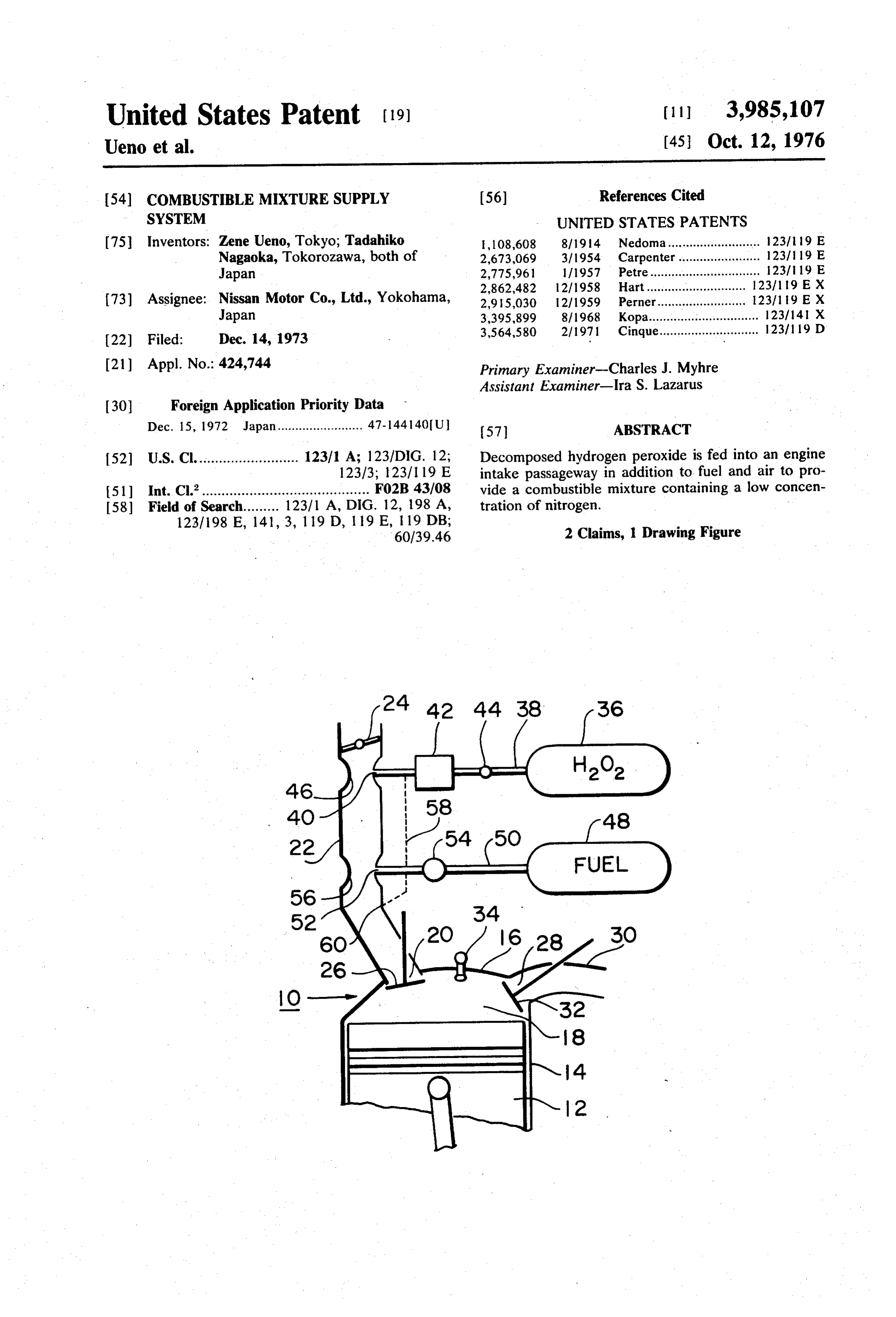
United States Patent (19) (11 3,985,107 Ueno et al. (45) Oct. 12, 1976
54) COMBUSTIBLE MIXTURE SUPPLY (56) References Cited SYSTEM UNITED STATES PATENTS 75 Inventors: Zene Ueno, Tokyo; Tadahiko l, 108,608 8/1914 Nedoma.......................... 123/19 E Nagaoka, Tokorozawa, both of 2,673,069 3/1954 Carpenter....................... 12311 19 E Japan 2,775,961 1/1957 Petre............................... 123/19 E (73) Assignee: Nissan
Japan
Motor Co., Ltd., Yokohama, 3,395,899
22 Filed: Dec. 14, 1973 3,564,580 2/1971 Cinque.................. ........ 12311 19 D 21) Appl. No.: 424,744 Primary Examiner-Charles J. Myhre Assistant Examiner-Ira S. Lazarus 30 Foreign Application Priority Data
Dec. 15, 1972 Japan........................ 47-144140 U. (57) ABSTRACT 52 U.S. Cl.......................... 123/1 A; 123/DIG. 12; Decomposed hydrogen peroxide is fed into an engine 123/3; 123/119 E intake passageway in addition to fuel and air to pro 51 Int. Cl’.......................................... F02B 43/08 vide a combustible mixture containing a low concen 58 Field of Search......... 123/1 A, DG. 12, 198 A, tration of nitrogen.
60/39.46 2 Claims, 1 Drawing Figure
Page 2
Drawing sheet — no readable text.
Page 3
disposed in the conduit 38 between the catalyst cham
COMBUSTIBLE MIXTURE SUPPLY SYSTEM ber 42 and the hydrogen peroxide source 36. The flow control valve 44 is manually or automatically operable
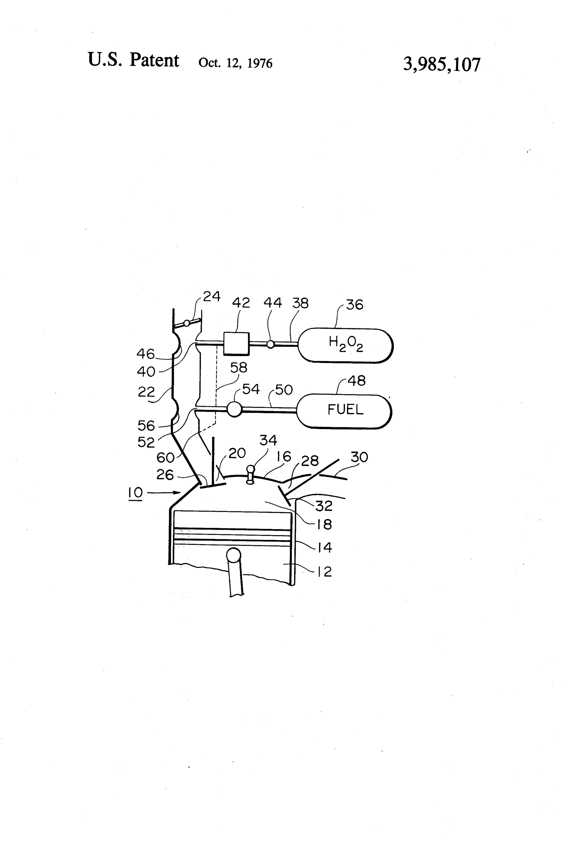
The present invention relates to a oxidizer supply to control the flow of hydrogen peroxide passing there system for an engine which is adapted to minimize the 5 through in accordance with the torque or load demands concentration of air pollutants in exhaust gases emitted of the engine 10. The catalyst in the catalyst chamber by the engine. 42 decomposes hydrogen peroxide supplied through It is well known in the art that noxious nitrogen ox the control valve 44 into water vapour and oxygen ides (NOx) are produced by combustion of a conven (HO +%O). The water vapor and oxygen are fed into tional combustible mixture in a combustion chamber of 10 the intake passageway 22 and mixed with air passing a combustion engine which pollute the atmosphere. therethrough. Silver, copper, etc. may be employed as This is because air is employed as an oxidizer for com the catalyst. A first venturi section 46 is formed in the bustion of fuel, and nitrogen oxides are formed by intake passageway 22 into which the port 40 opens. combination of oxygen with nitrogen which occupies The flow of air passing through the venturi section 46 about 78 per cent by volume of atmospheric air during 15 produces a vacuum therein to draw water vapour and combustion of fuel in an engine combustion chamber. oxygen from the conduit 38 into the venturi 46. The Thus, a reduction in the concentration of nitrogen in venturi section 46 also serves to assist or promote mix the combustible mixture is a solution to the problem of ing of water vapour and oxygen with air passing there minimizing the production of nitrogen oxides. through. A swirler or vane assembly may be provided in It is therefore an object of the invention to provide a 20 the intake passageway 22 or the venturi section 46 for oxidizer supply system to fill an engine combustion a similar purpose. : chamber with a combustible mixture containing a lo The engine 10 also includes a source 48 of fuel, concentration of nitrogen. . which communicates with the intake passageway 22 It is a further object of the invention to provide a through a conduit 50 and a fuel port 52 downstream of oxidizer supply system to fill an engine combustion 25 the port 40. A pump 54 is disposed in the conduit 50 chamber with a combustible mixture which burns at a which supplies or injects fuel from the fuel source 48 low temperature. into the intake passageway 22 in accordance with the It is a still further object of the invention to provide a torque or load demands of the engine 10. The pump 54 oxidizer supply system to supply a combustible mixture is actuated to feed fuel into the intake passageway 22 in containing a high concentration of oxygen. v 30 synchronism with the intake stroke of the piston 12 so These and other objects and advantages of the inven that fuel is fed into the mixture of air, water vapour and tion will become more apparent from the following oxygen passing through the intake passageway 22. The detailed description when taken in connection with the pump 54 may be driven by the engine 10 or any other accompanying drawing showing a schematic cross sec suitable means such as an electric motor. A second tional view of a preferred embodiment of a oxidizer 35 venturi section 56 is formed in the intake passageway supply system according to the invention connected to 22 into which the fuel port 52 opens. The venturi sec a combustion engine. tion 56 serves to assist or promote mixing of fuel with Referring now to the drawing, an engine 10 includes, the mixture of air, water vapour and oxygen passing as customary, a reciprocating piston 12, a cylinder 14 therethrough. A swirler or vane assembly may be pro accommodating the piston 12 therein and having a 40 vided in the intake passageway 22 or the venturi 56 for cylinder head 16, a combustion chamber 18 formed in a similar purpose. The flow of the mixture passing the cylinder head 16, an intake port 20 formed through through the venturi 56 produces a vacuum therein to the cylinder head 16 and opening into the combustion draw fuel from the conduit 50 into the venturi 56. A chamber 18, a combustible mixture intake passageway branch passageway or conduit 58 may be provided 22 communicating with the intake port 20 and vented 45 which branches off from the conduit 38 downstream of to the open air through an engine air cleaner (not the catalyst chamber 42 and which communicates with shown), a throttle valve 24 movably mounted in the the intake passageway 22 downstream of the fuel port intake passageway 22, an intake valve 26 disposed in 52 as shown at a point 60 in the drawing. The branch the intake port 20, an exhaust port 28 formed through conduit 58 serves to supply additional water vapour the cylinder head 16 and opening into the combustion 50 and oxygen into the intake passageway 22. chamber 18, an exhaust passageway 30 communicating In operation, air is drawn through the air cleaner (not with the exhaust port 28 and vented to the open air shown) into the intake passageway 22 past of the throt through a silencer (not shown), an exhaust valve 32 tle valve 24 during the intake stroke of the piston 12. disposed in the exhaust port 28, and a spark plug 34 Water vapour and oxygen resulting from decomposi disposed in the combustion chamber 18. The throttle 55 tion of hydrogen peroxide are injected through the valve 24 is manually operable to control the flow of air conduit 38 and the port 40 from the catalyst chamber passing through the intake passageway 22 in accor 42 into the venturi 46 and mixed with air passing there dance with the torque or load demands of the engine through. The mixture of air, water vapour and oxygen 10. passes through the intake passageway 22 toward the The engine 10 is provided with a source 36 of an 60 fuel port 52. Fuel is injected through the conduit 50 oxidizer, here described as being a compound of oxy and the fuel port 52 from the pump 54 into the intake gen such as hydrogen peroxide (H2O). The hydrogen. passageway 22 and mixed with the mixture of air, water peroxide source 36 communicates with the intake pas vapour and oxygen passing therethrough to form a sageway 22 through a conduit 38. The conduit 38 combustible mixture. The combustible mixture is opens into the intake passageway 22 through a port 40 65 drawn through the intake port 20 into the cylinder 14 downstream of the throttle valve 24. A decomposer and burned in the combustion chamber 18 after being such as a catalyst chamber 42 having a catalyst therein compressed by the piston 12. Since the water vapour is disposed in the conduit 38. A flow control valve 44 is and oxygen reduce the concentration of air or nitrogen
Page 4
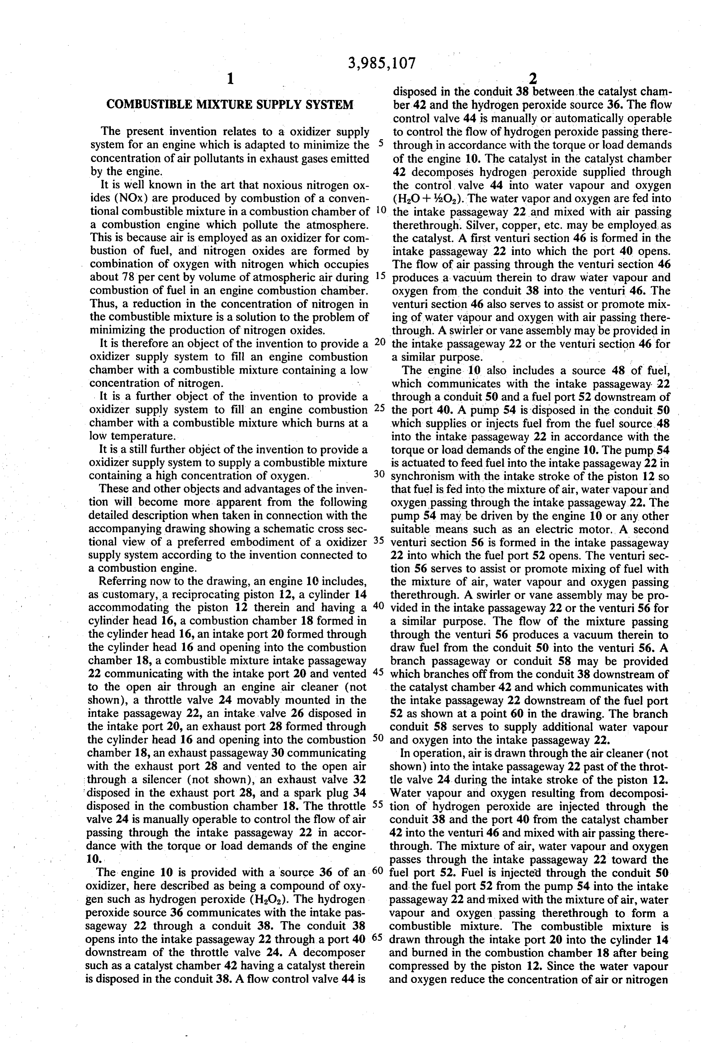
in the combustible mixture and the water vapour serves tion of said intake passageway with which said source to reduce the temperature of combustion of the com of fuel communicates, in which said oxidizer supply bustible mixture, production of nitrogen oxides is mini system further comprises a branch passageway commu mized. Since oxygen is added to increase the concen nicating with said conduit downstream of said decom tration of oxygen in the combustible mixture, the com poser and opening into said intake passageway down bustible mixture is efficiently burned to minimize the stream of said section.
production of hydrocarbons (HC) and carbon monox 2. A combination of an engine having a combustion ide (CO). chamber, an intake passageway providing communica It will be understood that reduction or elimination of tion between said combustion chamber and the ouside
air pollutants in engine exhaust gases is attained by the atmosphere, and a source of fuel communicating with invention. said combustion chamber, with an oxidizer supply sys Although the invention has been described as being tem comprising a source of hydrogen peroxide and a applied to a reciprocating engine, the invention can be conduit leading from said source of hydrogen peroxide applied to other various combustion engines such as 15 to said intake passageway, said intake passageway
What is claimed is: being formed therein with a venturi, said conduit open ing 1. A combination of an engine having a combustion thereinto into said venturi to cause oxidizer to be drawn chamber, an intake passageway providing communica combustion when air passes through said venturi into said tion between said combustion chamber and the outside chamber in which said oxidizer supply 20 system further atmosphere, and a source of fuel communicating with said conduit between comprises a decomposer disposed in said combustion chamber, with an oxidizer supply sys and said intake passageway said source of hydrogen peroxide operative to decompose tem comprising a source of hydrogen peroxide and a hydrogen peroxide passing therethrough, conduit leading from said source of hydrogen peroxide and a flow to said intake passageway, said intake passageway 25 source of hydrogen peroxide and said decomposer,said control valve disposed in said conduit between
being formed therein with a venturi, said conduit open which said decomposer comprises a catalyst, in which ing into said venturi to cause oxidizer to be drawn thereinto when air passes through said venturi into said said venturi is formed in said intake passageway up combustion chamber, in which said oxidizer supply stream of a section of said intake passageway with system further comprises a decomposer disposed in which said source of fuel communicates, in which said said conduit between said source of hydrogen peroxide 30 oxidizer supply system further comprises a branch pas and said intake passageway operative to decompose sageway communicating with said conduit downstream hydrogen perioxide passing therethrough in which said of said decomposer and opening into said intake pas decomposer comprises a catalyst, in which said venturi sageway downstreamk of. said. section.
is formed in said intake passageway upstream of a sec 35
Provenance
- Collection
- Cited prior art
- Original PDF
- patentimages.storage.googleapis.com →
- Filed
- 1973-12-14
- Pages
- 4
- Method
- pdftotext (the PDF's own text layer) + pdftoppm 300dpi page scans
- Source
- Google Patents bibliographic record
- Granted
- 1976-10-12
- Inventors
- Zene Ueno; Tadahiko Nagaoka; Nissan Motor Co Ltd
- Transcribed from
- patentimages.storage.googleapis.com →