patent · US4388966
Buried heat exchanger
21 June 1983
Page 1 — bibliographic record
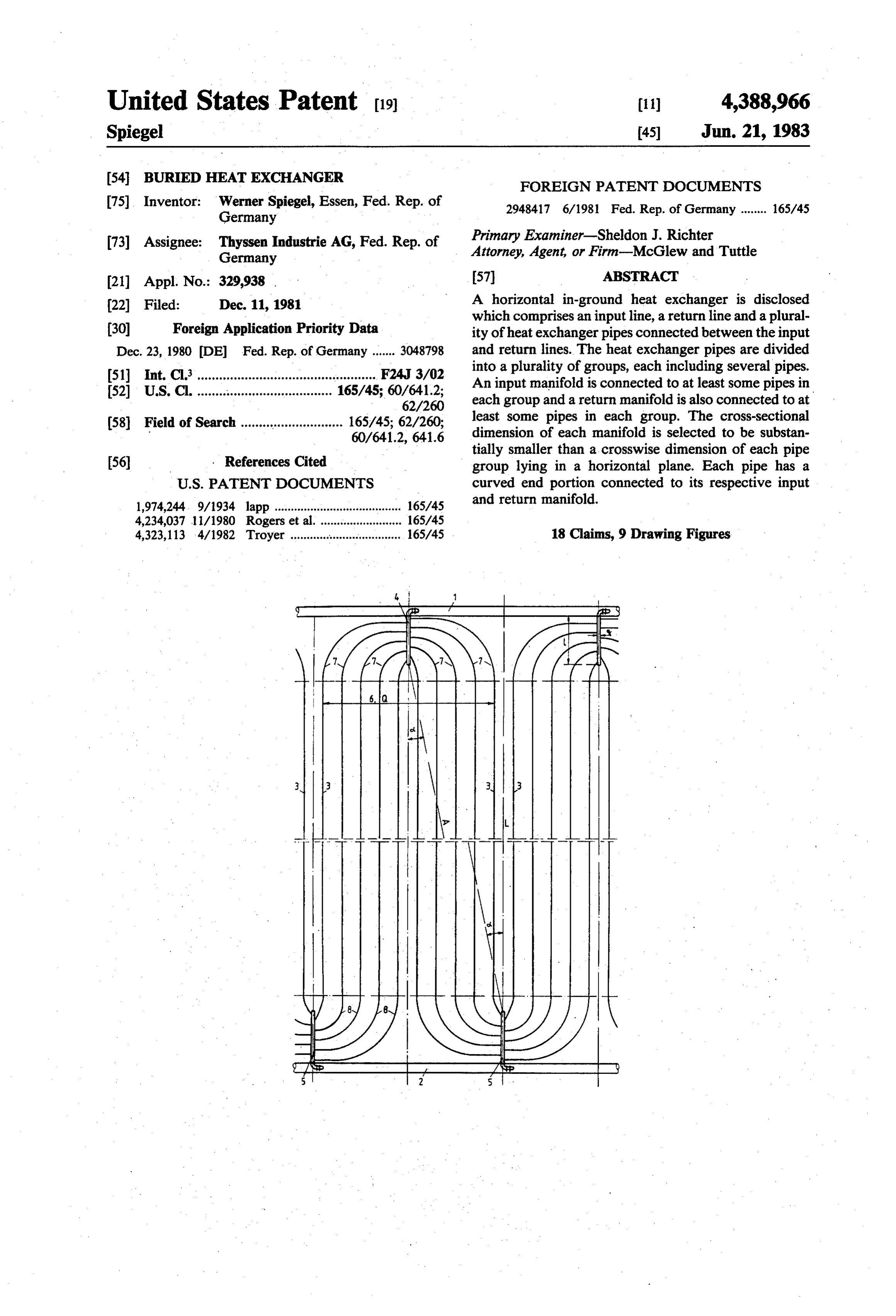
United States Patent (19) 11) 4,388,966 Spiegel 45 Jun. 21, 1983 (54 BURIED HEAT EXCHANGER FOREIGN PATENT DOCUMENTS (75). Inventor: Werner Spiegel, Essen, Fed. Rep. of 2948417 6/1981 Fed. Rep. of Germany ........ 165/45 Germany 73 Assignee: Thyssen Industrie AG, Fed. Rep. of Primary Examiner-Sheldon J. Richter Germany Attorney, Agent, or Firm-McGlew and Tuttle 21 Appl. No.: 329,938 . 57 ABSTRACT 22 Filed: Dec. 11, 1981 A horizontal in-ground heat exchanger is disclosed which comprises an input line, a return line and a plural (30) Foreign Application Priority Data ity of heat exchanger pipes connected between the input Dec. 23, 1980 DE Fed. Rep. of Germany ....... 3048798 and return lines. The heat exchanger pipes are divided 51 int. Cli................................................. F24J 3/02 into a plurality of groups, each including several pipes.
52 U.S. C. ........ see a see see a see also as sea as a so 165/45; 60/641.2;
An input manifold is connected to at least some pipes in 62/260 each group and a return manifold is also connected to at 58) Field of Search ............................ 165/45; 62/260; least some pipes in each group. The cross-sectional 60/641.2, 641.6 dimension of each manifold is selected to be substan tially smaller than a crosswise dimension of each pipe 56) . References Cited group lying in a horizontal plane. Each pipe has a
and return manifold.
1,974,244. 9/1934 lapp ....................................... 165/45 4,234,037 li/1980 Rogers et al. ......................... 165/45 4,323,113 4/1982 Troyer ............os so os ssa ow we so saw a v 165/45 18 Claims, 9 Drawing Figures
Page 2
Drawing sheet — no readable text.
Page 3
Drawing sheet — no readable text.
Page 4
Drawing sheet — no readable text.
Page 5
Drawing sheet — no readable text.
Page 6
Drawing sheet — no readable text.
Page 7
Drawing sheet — no readable text.
Page 8
Drawing sheet — no readable text.
Page 9
Drawing sheet — no readable text.
Page 10
input and return manifolds each have a cross sectional
BURIED HEAT EXCHANGER dimension which is substantially less than a crosswise
FIELD AND BACKGROUND OF THE
dimension, in the plane, of each group of pipes. Each
INVENTION
pipe has a curved end portion connected to at respec tive input and return manifolds.
The present invention relates in general to heat ex The present invention is directed to a heat exchanger changers and, in particular to a new and useful heat of the above-mentioned kind in which the stresses due exchanger which is meant to be horizontally disposed in to thermal loads of the cooling or heat exchange pipes the ground, which can be utilized as a waste heat heat 10 and associated manifolds are eliminated to a large ex exchanger for power plants or to absorb excess heat tent, especially at the respective connections, so as to from the ground. ensure a long life of the heat exchanger. The utilization of waste heat from various sources, Another object of the invention is to provide a heat has become a priority problem. Particularly in power exchanger wherein the lengthwise dimension, in a di plants, great amounts of energy are produced which are rection parallel to the longitudinal extension of the heat dissipated to the ambience in cooling towers. The use of 15 exchange pipes, is selected to be smaller than the cross wet cooling towers for dissipating waste heat is becom wise dimension of the pipe groups.
ing more and more restricted by water economies and A further object of the invention is to position the the use of dry cooling towers developed recently leads input manifolds, with respect to the return manifolds, at to a reduced utilization of the primary energy in the a staggered location along the input and return lines so
that a connecting line between the input and return
A horizontally extending, buried heat exchanger is manifolds connected to pipes of a single group extends known for use as a cooling system for power plants, at an oblique angle to the longitudinal axis of the pipes. which utilizes the water-carried waste heat for warming Another object of the invention is to provide a heat agricultural areas. This makes it possible to increase exchanger wherein each group is supplied by a single agriculture yields, extend the period of growth, in input manifold
and connected to two return manifolds prove produce quality, and cultivate non-native plants. which are located symmetrically about a central longi Further advantages are that the waste heat is employed tudinal axis of the group.
in a manner which is kind to the enrironment, so that A still further object of the invention is to provide the location of the power plant can be chosen more such a heat exchanger wherein the curved end portions freely and, as compared to power plants with dry cool 30 of each pipe is approximately identical, particularly ing towers, the efficiency is improved. within one group of pipes and preferably for all cooling In the prior art heat exchanger, the geometry of em bedding the unit is such that at the forward and return pipes of all groups.
A still further object of the invention is to provide a ends of a certain amount of parallel extending cooling pipes, manifolds supplying and discharging the pipes are 35 heat exchanger which is simple in design, rugged in provided, each comprising a straight pipe which ex construction and economical to manufacture. tends perpendicularly to the cooling pipes, in a length The invention starts from the idea of minimizing the corresponding to, or slightly exceeding, the crosswise occurring stresses in the entire system of cooling pipes extension of the associated group of cooling pipes. by designing it in a geometry slackening the structure and permitting an almost complete compensation for
These manifolds are connected to the forward or return line through a short connecting tube. The individual dilation so that no tensional and/or compressive stresses groups of cooling pipes are laid in the pattern of a grate worth mentioning are transmitted to the manifolds serv which is quasi-rigidly fixed on its sides formed by the ing the individual groups of cooling pipes. two straight, manifolds, so that the occurring variations The curved end portions, as a rule, are formed by the in length of the cooling pipes represent a strong me 45 ends of the cooling pipes themselves, which are de chanical load on the system. This makes the strength signed with a definite excess length for this purpose. over time and the life of the system unsatisfactory and, Usually, these ends are made of the same material as the particularly in power plants, the requirements of econ cooling pipes, preferably of a plastic such as hard poly omy and safety are not met to a sufficient extent. This is ethylene. The bends with the required length and cur due to the dilations and contractions of the mostly sev 50 vature are made at the site, or already provided on eral hundred meters long cooling pipes under tempera prefabricated pipes. The curved ends, of course, also tures varying between a cold state and an operating participate in the function of transferring heat to or level, which are hindered by the straight manifolds from the soil, so that the heat-exchange surface is not which are substantially fixed in their filled up trenches. reduced as compared to prior art systems. 55 A minimum-stress, slackened structure of the bedded
SUMMARY OF THE INVENTION cooling pipes may also be obtained with manifolds ac Accordingly, an object of the present invention is to cording to the invention which are simple to manufac provide a heat exchanger to be mounted horizontally in ture and sufficiently long, thus permitting a great num the ground, comprising an input line, a return line, a ber of connections for the end portions of the cooling plurality of heat exchange pipes disposed substantially 60 pipes.
in a plane and substantially equi-distantly spaced from The staggering of manifolds according to the inven each other, the pipes being assembled into a plurality of tion provide for a favorable symmetry of the individual groups of a plurality of pipes each, an input manifold groups of cooling pipes and, consequently, permits the connected to one end of at least some of the pipes in making of curved end portions which are widely identi each group and a return manifold connected to an oppo 65 cal or similar, and thus lay the pipes in a pattern which site end of at least some of the pipes in each group. Each is well compensating for length variations. input manifold is connected to the input line and each The design according to another inventive feature, return manifold is connected to the return line. The reduces the number of needed manifolds and also of
Page 11
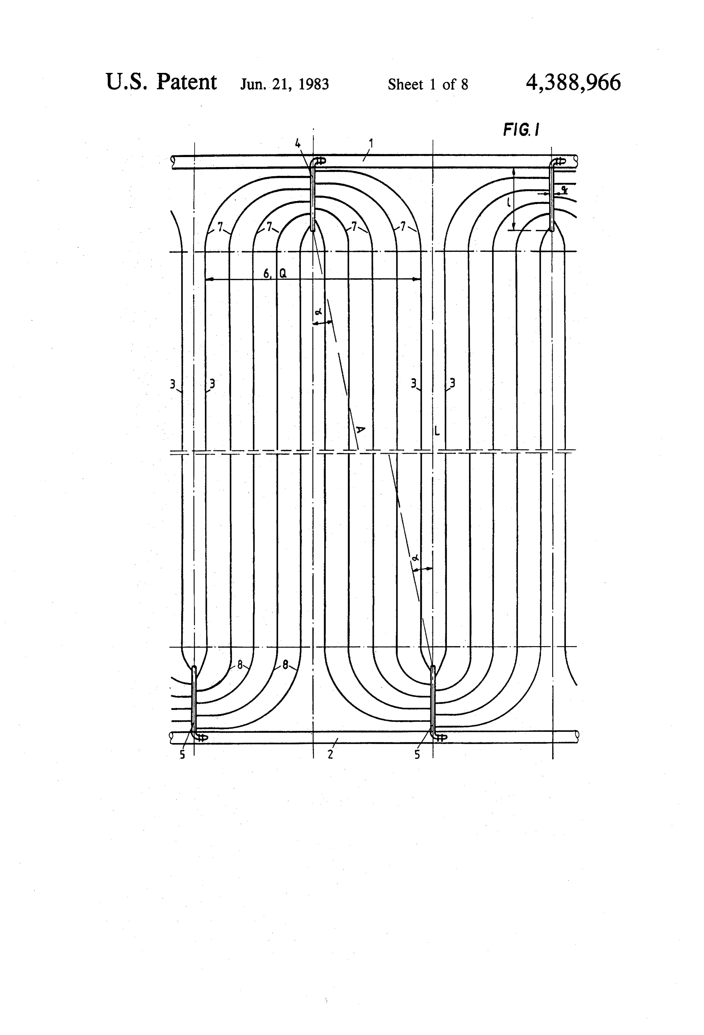
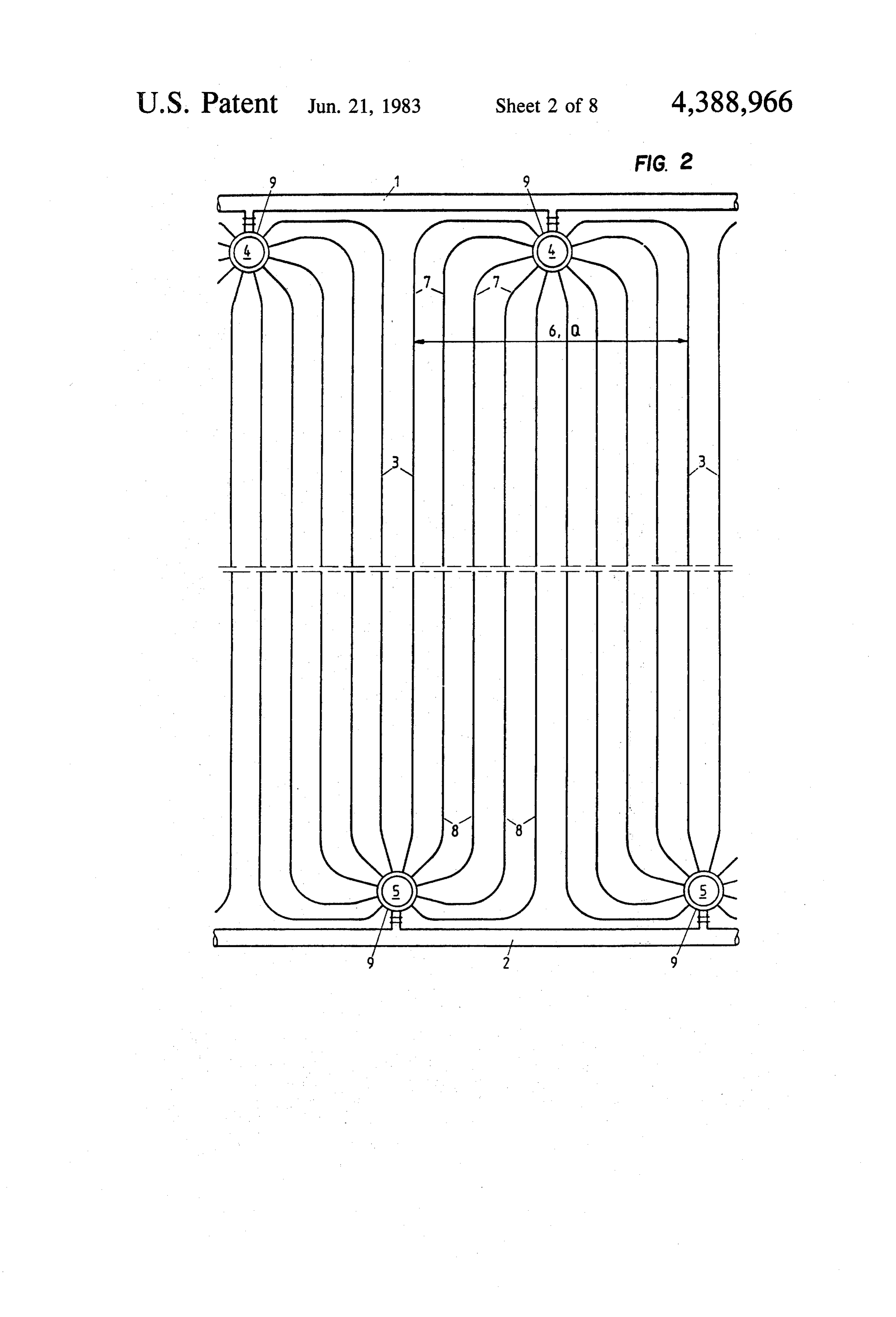
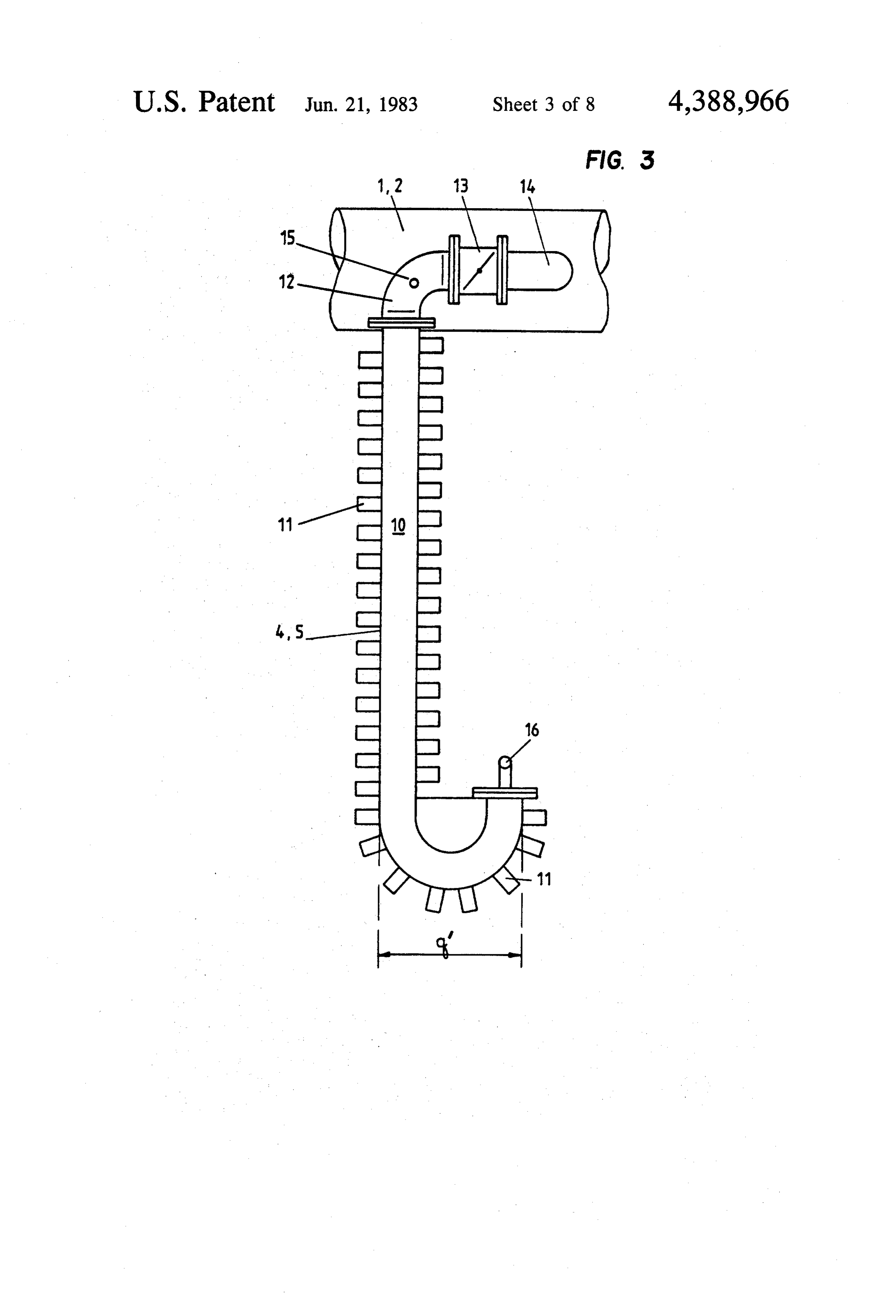
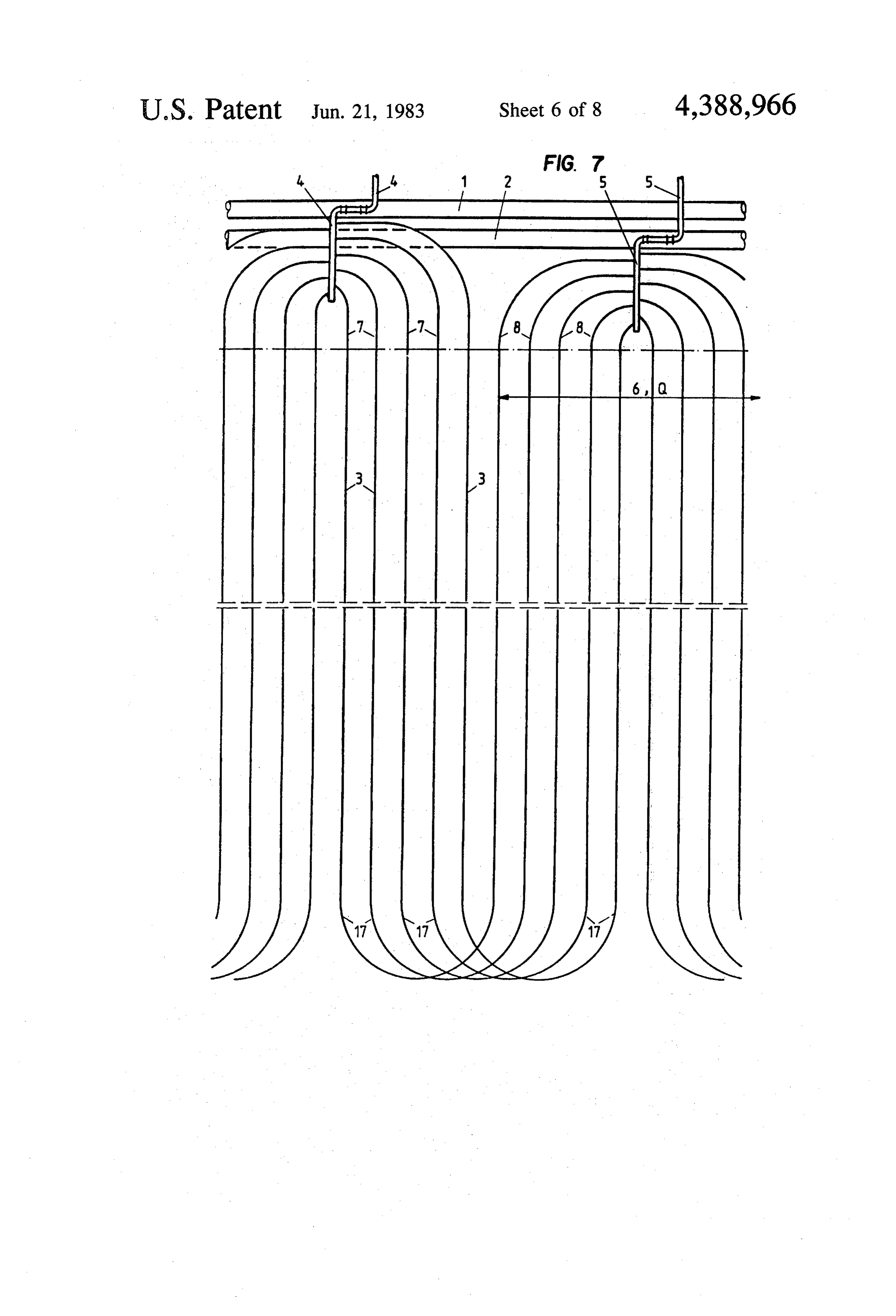
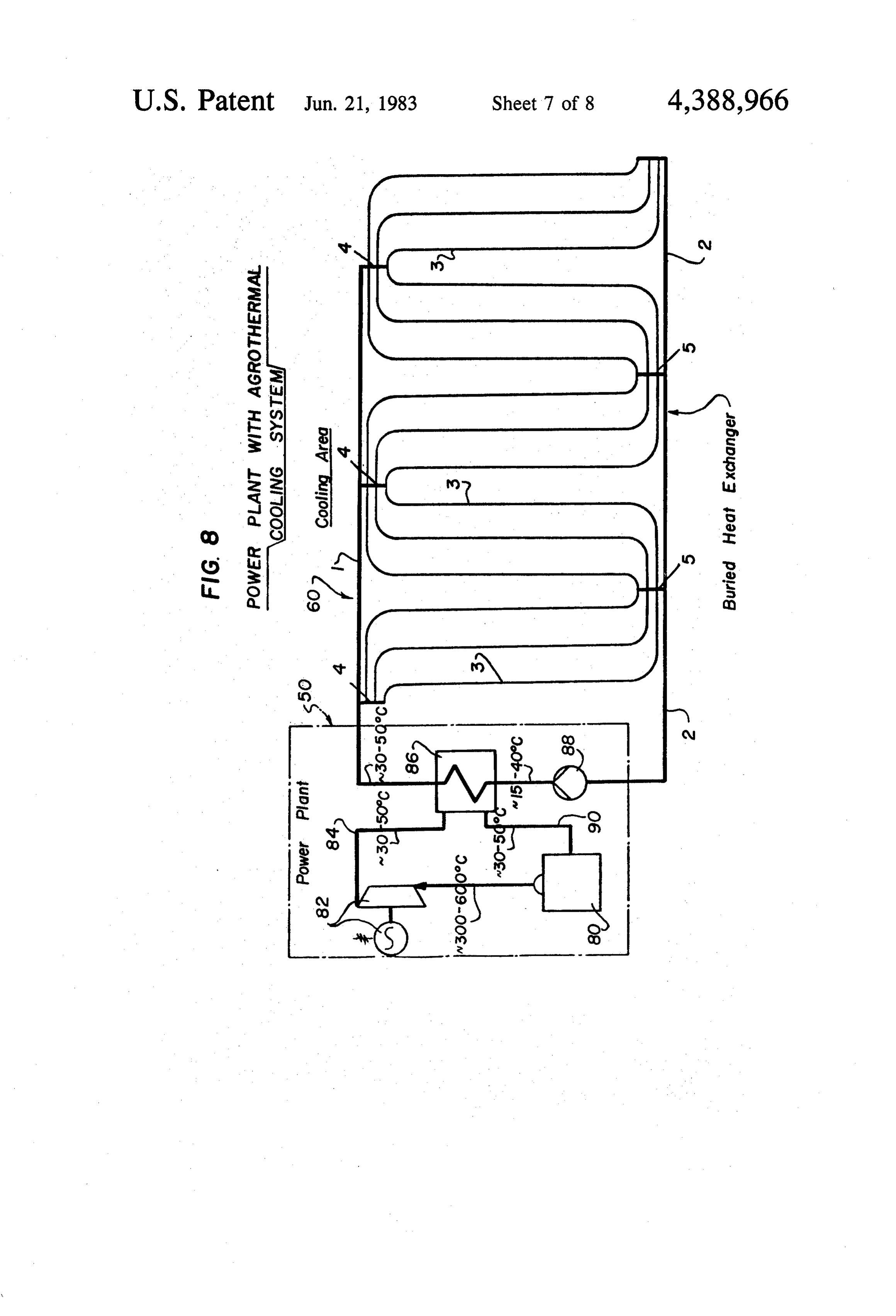
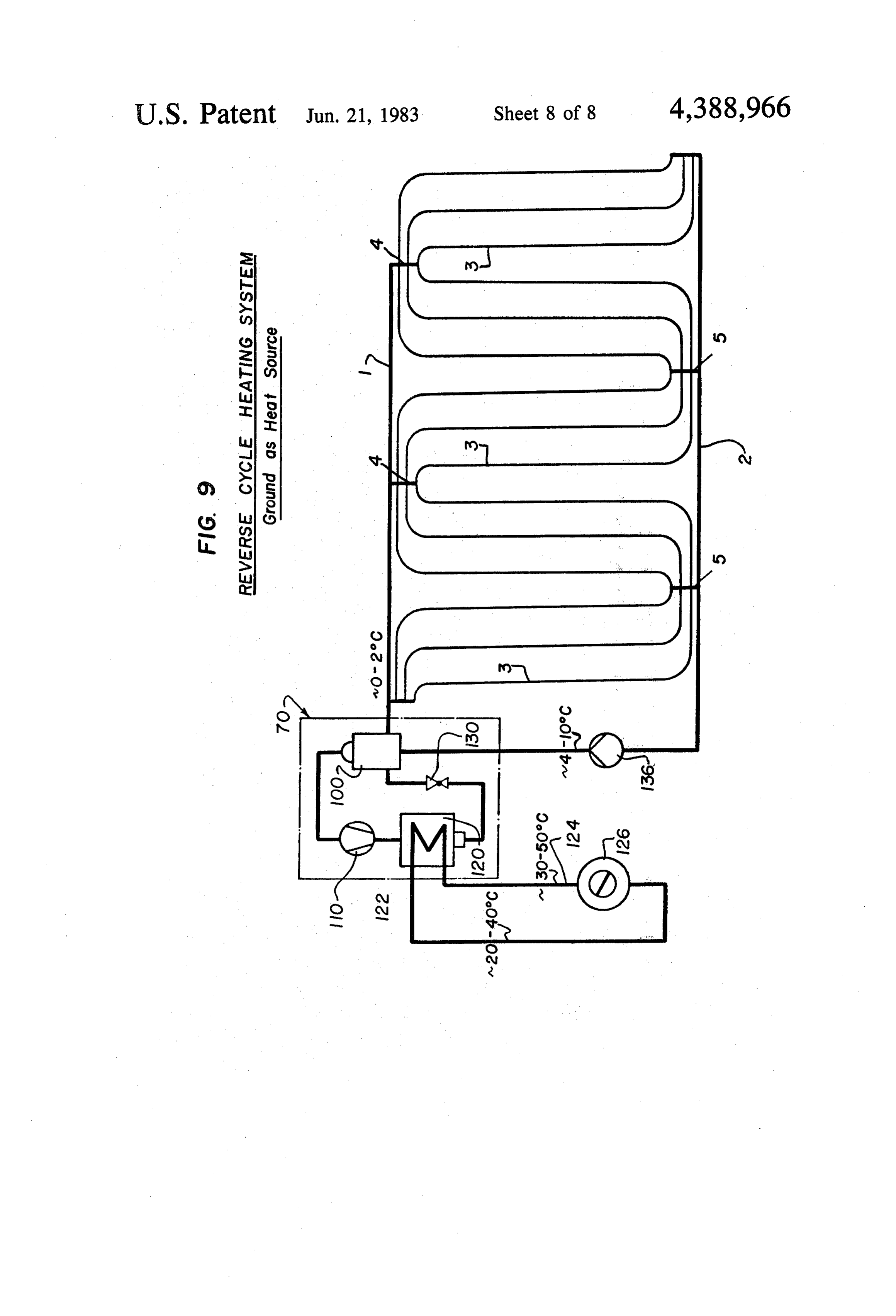
shut-valves for controlling the water flow, so that main FIG. 1 is partial top plan view of a heat exchanger; tenance and supervision are simplified while preserving FIG. 2 shows the heat exchanger of FIG. 1 with the slack laying. This is an optimal utilization of the modified manifolds;
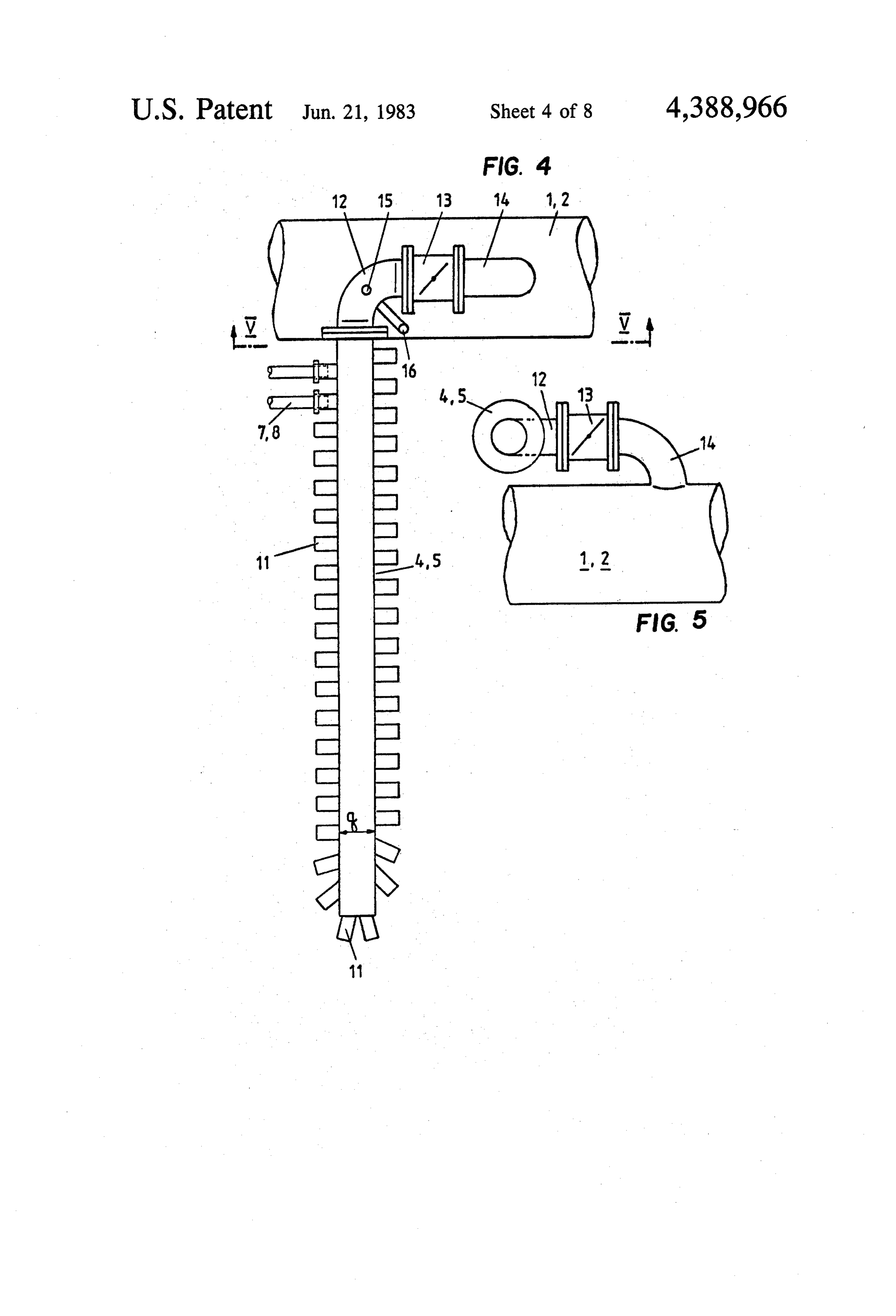
available wall surface of the manifolds in view of the FIG. 3 shows another embodiment of the manifolds; maximum possible circulation of the water. FIG. 4 is an enlarged view of a manifold correspond The requirement of making all of the individual cool ing to FIG. 1;
ing pipes within a similar group as uniform as possible, FIG. 5 is a sectional view taken along the line V-V with regard to their minimum dilation, calls for a design of FIG. 4;
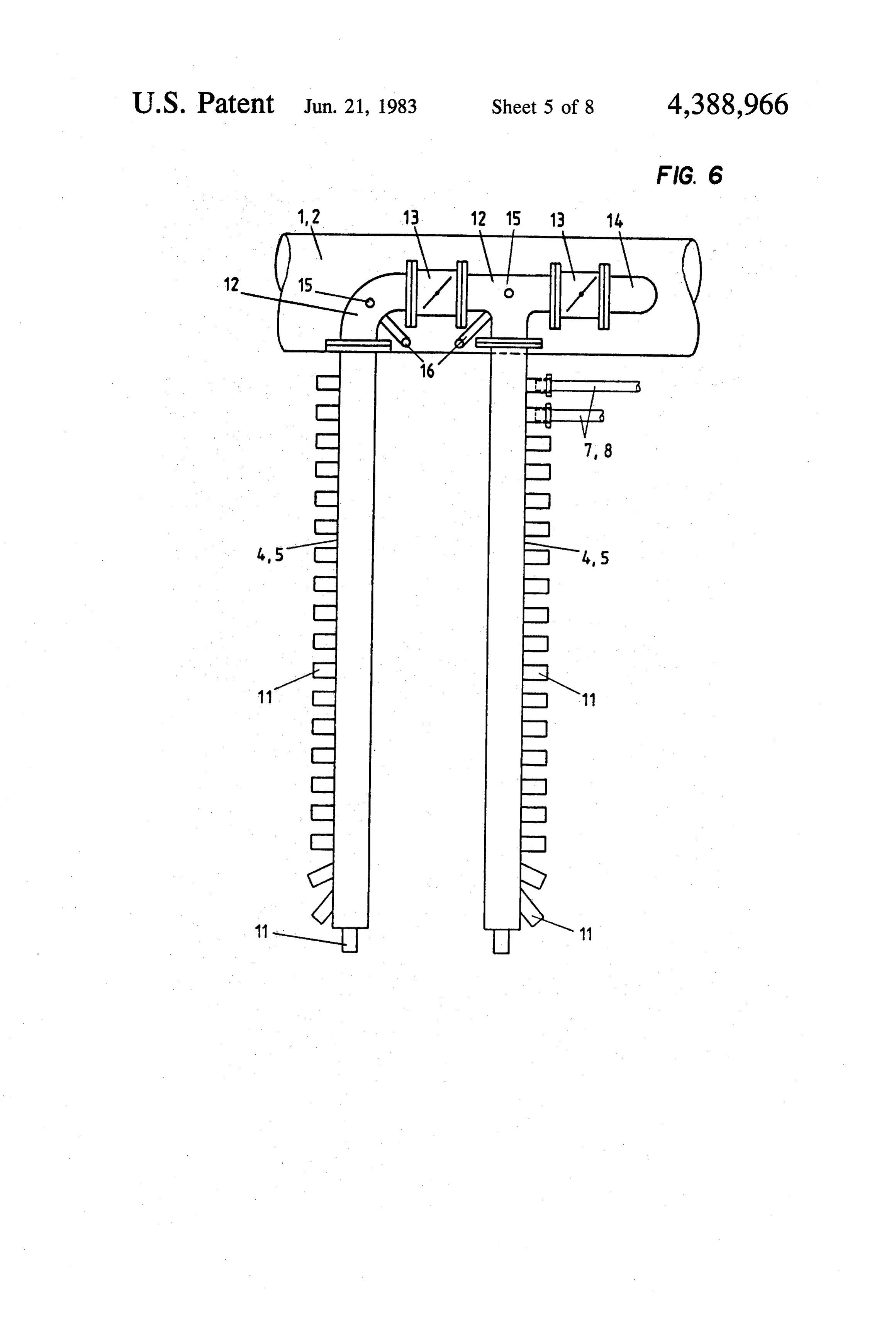
of the pipes so that they include approximately identical FIG. 6 shows still another embodiment of the mani curved end portions. This design also leads to uniform 10 folds; W pressure drops in the lines and a correspondingly uni FIG. 7 is a partial view of a heat exchanger having its form transfer of heat to or from the soil. forward end return lines led close to each other; The curved end portions between the straight ones of FIG. 8 is a diagrammatical layout of a bed-type cool the cooling or heat exchange pipes and the manifolds ing circuit of a power plant; and also provide heat-exchange surfaces and perform there 15 FIG. 9 is layout of a similar, reversed-cycle system fore the same function as the straight and paralleld using the ground as a source of heat. cooling pipes. It is advisable in accordance with another feature of the invention to use pipes of such extension DESCRIPTION OF THE PREFERRED that the individual cooling pipes along with their two EMBODIMENTS cured end portions can be made of a single pipe length, 20 Referring to the drawings in particular, the invention at least in instances where it is not necessary, for pur embodied therein comprises a horizontal inground heat poses of handling, to employ shorter pieces. exchanger having a plurality of groups of several heat A still further object of the invention is to provide exchange pipes each connected through input and re such a heat exchanger wherein at least some of the pipes turn manifolds to respective input and return lines 1 and includes straight ends connected between the curved 25 2.
end portions and the respective manifolds. In the heat exchanger shown in FIG. 1, a hot (cold) The end portions of the cooling pipes need not be water curved over their entire lengths. They may comprise a return forward or input line 1 and a cool (hot) water line 2 are laid in two trenches (not shown) which straight parallel portion, for example, a middle portion, are spaced especially if manifolds of particularly compact design 30 tance. Linesfrom each other by a predetermined dis 1 and 2 are connected to each other, with are provided.
A particularly compact inventive manifold may be the interposition of manifolds 4,5, through a large num designed as a short, hollow vertical cylinder, with the ber of parallel and equidistantly spaced heat exchange connections for the curved end portions of the cooling pipes 3. The individual manifolds 4, 5 each supply or pipes being provided in one or more rows on the outside 35 discharge a group 6 the water to be cooled or heated into or from of several heat exchange pipes 3.
of the cylinder. Such a manifold, which has circular While it is understood that the invention can be used horizontal cross-section, is particularly space saving both for heating and cooling purposes, the following and makes it possible to connect a great number of pipes to the manifold. Further, the manifold may be fixed in description will assuma a use of the invention to dissi place while using its hollow, so that the wanted com pate heat into the ground.
pensation for extension can be obtained in the curved ingInpipes the simplified view of FIG. 1, the group 6 of cool comprises ten cooling pipes 3. In practice, end portions of the cooling pipes without a risk of dam aging the system. however, this number is substantially larger, for exam Further advantageous designs of the manifolds, pro ple, forty cooling pipes 3. The end portions 7, 8 of cool vide for a simple, inexpensive manufacture and laying 45 ing pipes 3, connected to manifolds 4, 5, are curved by operation, particularly if a very large number of cooling bending the excess length of the straight lead pipes pipes is to be connected thereto. which are made of a plastic, such as polyethylene. In the To vary the cooling or heat exchange characteristic, plane of bedding of the cooling pipes, the cross-sec the cooling pipes which are otherwise connected in tional dimension q of manifolds 3,4 is very small as parallel in the heat exchanger, may be connected in '50 compared to the crosswise extension Q of cooling pipe series. group 6, and the length 1 of the manifolds is also much Should it be provided to lay the hot water forward smaller than this extension Q.
line and the cool water return line in a common trench, Forward line manifolds 4 are staggered relative to for example, a U-shaped return bend can be provided return line manifolds 5, so that a connecting line A near the middle of each pipe. 55 between opposite manifolds forms a definite angle a The various features of novelty which characterizes with the central longitudinal axis L of group 6 or with the invention are pointed out with particularity in the the longitudinal axis of cooling pipes 3. In a specific claims annexed to and forming a part of this disclosure. instance, an angle a is to be provided taking into ac For a better understanding of the invention, its operat count the respective desired cooling characteristic of ing advantages and specific objects attained by its uses, 60 the system depending on the length of cooling pipes 3, reference is made to the accompanying drawings and their spacing, and the number of cooling pipes in the descriptive matter in which preferred embodiments of group. The cooling pipe group 6 supplied through a the invention are illustrated. single forward line manifold 4 connects to two return BRIEF DESCRIPTION OF THE DRAWINGS 65 line manifolds 5 provided at locations which are sym metrical relative to the central longitudinal axis L of
In the following, some embodiments of the invention group 6. The sum of the lengths of curved end portions are explained in more detail with reference to the draw 7 at the supply side, and 8 at the return side, is substan ings in which: tially identical for all of the cooling pipes 3.
Page 12
: The embodiment of FIG. 2 differs from FIG. 1 in that there is insufficient temperature differential to obtain a manifolds 4,5 are modified. They are designed as short desired heating or cooling by a single parallel passage of vertical cylinders 9 having a circularly cylindrical Water.
water space. The radius of the cylinder is very small as FIG. 7 is a partial view of a system in which the hot compared to the crosswise extension Q of cooling pipe water forward line 1 and the cool water return line are group 6. Again ten cooling pipes are shown in FIG. 2, laid in a common trench, close to each other. In this while in practice, the number of cooling pipes may be case, the invention may also be applied in a simple way 40 and more. To be able to connect such a great number by designing cooling pipes 3 as loops having a U-shaped to the outside of the cylinder wall of the manifold 4,5, return bend 17 about in the middle of their length. In the connections are provided in two or more rows one 10 this design again, the end portions 7 at the forward line above the other (not shown). In this embodiment also, and the end portions 8 at the return line of cooling pipes the sum of the lengths of end portions 7, 8 is approxi 3 are curved or bent in the manner described above, and mately identical for all of cooling pipes 3. the manifolds comply with the dimensional conditions Another embodiment of the manifolds 4,5 is shown in with respect to the crosswise extension of the respective FIG. 3. The manifold comprises a J-shape tube having 15 group of cooling pipes. As indicated in FIG. 7, mani forty pipe connections 11 which project perpendicu folds 4,5 may extend beyond (upwardly in the figure) larly from the tube wall and to which the end portions forward and return lines 1, 2 to be connected to, and 7, 8 of cooling pipes 3 can be connected. Manifold 4,5 is serve, a further system. For such a purpose, the mani connected through an elbow 12 to a shut-off valve 13, fold according to FIG. 2 (claim 10) with the cylindrical, and a connection 14 to hot water forward line 1 or cold 20 vertically extending wall is also very satisfactory. water return line 2. Further connections 15, 16, which The inventive heat exchanger buried in the ground are normally closed, permit emptying to and venting and including a great number of cooling pipes mostly from the cooling pipe group. The location of these having a length of several hundred meters provides a manifolds 4,5 within the system corresponds to that correspondingly extended free area for agricultural shown in FIG.1. Their cross-sectional dimension q is 25 utilization. The zone of the hot water forward line 1, the very small in comparison with the crosswise extension associated manifolds 4 and end portions 7, usually pro Q of the associated group 6 of cooling pipes. vides an area of particularly high density of available The manifolds of FIG. 1 are shown enlarged in FIG. waste heat. Advantageously, this may be utilized for 4 (top plan view) and FIG. 5 (section along the line placing in the area of greenhouses for hot-house plants, V-V of FIG. 4). They comprise a straight cylindrical 30 with the hot water line being left exposed, to obtain a tube extending in the central longitudinal axis L of the high heat transfer through air convection. associated groups 6 of cooling pipes (FIG. 1). Manifold As mentioned previously the heat exchanger of the 4, 5 is provided with pipe connections 11 for coaxially invention can be used both to discharge heat into the receiving the individual end portions 7, 8 of cooling ground and to receive heat from the ground. When used pipes 3. At the end of manifold 4,5, some of connections 35 to receive heat from the ground the input line 1 be 11 project from the tube wall in oblique directions for comes a cold water line and the return line 2 becomes a this purpose. Other elements are designated with refer hot water line.
ence numerals corresponding to those in the preceding Turning to FIG. 8, the heat exchanger, in the form of figures. an agro thermal cooling system is shown connected to a In the embodiment of FIG.6, manifold 4,5 comprises power plant. The powerplant generally designated 50 is two cylindrical tubes extending substantially symmetri shown adjacent an area of earth generally designated 60 cally of the central longitudinal axis L of the respective which is to receive the waste heat. The power plant group 6 of cooling pipes (FIG. 1). Each of the two tubes comprises a stream generator 80, connected to a turbine of this manifold supply or discharge one half of the generator 82. Saturated steam travels over line 84 to cooling pipes of the group, which makes it possible, by 45 condensor 86 which is supplied with cool medium, means of provided shut-off valves 13, to adjust different preferably water by a pump 88. The condensate is sup rates of flow therethrough. Particularly, while provid plied over line 90 back to the steam generator 80. The ing manifolds of this embodiment at only some of loca pump 88 and condensor 86 are connected to the hot tions of the system, it is possible to shut off one part in water input line 1, of the heat exchanger, and to the case of a disturbance. Other reference numerals again 50 return line 2. w a indicate like elements in the preceding figures. In FIG. 9, the invention is shown connected to a The functions of hot water forward line 1 and cool power plant, such as a nuclear power plant which has water return line 2, i.e., the water flow, may occasion an upper temperature limit which can be above the 600' ally be reversed, if desired for obtaining a particular sea limit of the power plant in FIG. 8. cooling characteristic. Means therefore are conven 55 In that figure, the power plant generally designated tional (not shown). The cooling pipes of group 6 may 70 includes a compressor 11 which supplies medium also be connected to each other in series. By disconnect from an evaporator 100 to a condensor and heat ex ing them from the respective line, i.e., shutting off two changer 120. The fluid is then supplied over a pressure adjacent manifolds 4,5 of the forward and return line reducing valve 130 back to the evaporator 100. Heat 1,2, respectively, so that then the water flows, for exam exchanger 120 is connected over lines 122 and 124 to a ple, from the hot water forward line through a first, stillpoint of use of the heat at 126. Heat transfer medium is open manifold 4 into one half of the cooling pipe group pumped using a pump 136 to the evaporator 100. The and therefrom through a second, now shut-off manifold input line 1 receives fluid from the line containing pres 5 into the following half of the cooling pipe group and sure reducing valve 130. The remaining features are through a third, again shut offmanifold 4 into the next 65 designated with numerals corresponding to those used half of a cooling pipe group, to be discharged only in the previous figures.
through the manifold 5 which is not shut off, into the It is noted that the medium is preferably a mixture cool water return line 2. This may be desirable when containing water plus an antifreeze, such as a 65% by
Page 13
volume water and 35% by volume ethylene glycol tive manifold for supplying medium to said respective mixture. To this mixture an anticorrosion agent can be manifold and a second plurality of pipes having curved added in known fashion. end portions connected to said manifold for discharging The invention can be stated generally as being a hori fluid from said manifold, the sum of the curved end Zontal inground heat exchanger comprising: portions of said first plurality of pipes being approxi an input line (1); mately the same as the sum of said second plurality of a return line (2); plpes.
a plurality of heat exchange pipes (3) disposed sub 7. A heat exchanger according to claim 1, wherein stantially in a plane and substantially distantly spaced each pipe with its connected curved end portions is from each other, said pipes being assembled into a plu 10 made as a single member.
rality of groups (6) of a plurality of pipes each; 8. A heat exchanger according to claim 1, wherein at an input manifold (4) connected to one end of at least least some of said heat exchange pipes have a straight some of the pipes in each group; and portion connected between the curved end portion a return manifold (5) connected to an opposite end of thereof and a respective manifold.
at least some of the pipes in each group; 9. A heat exchanger according to claim 1, wherein at each input manifold connected to said input line and 15 least some of said heat exchange pipes include a second each return manifold connected to said return line; curved portion spaced from said first mentioned curved said input and return manifolds each having a cross portion and a straight portion between said first men sectional dimension (q) which is small with respect to a tioned and second curved portions, crosswise dimension (Q) of each group (6) in the plane; 20 10. A heat exchanger according to claim 1, wherein each pipe having a curved end portion (7,8) con each manifold comprises a vertical cylinder with a cir nected to a respective input and return manifold. cular cylindrical cavity defined therein, the curved end While specific embodiments of the invention have portions of said heat exchange pipes connected to said been shown and described in detail to illustrate the cavity in at least one application of the principles of the invention, it will be 25 11. A heat exchanger according to claim 1, wherein understood that the invention may be embodied other each manifold comprises a J-shaped tube with most of wise without departing from such principles. the curved end portions of said pipes connected to each The embodiments of the invention in which an exclu respective manifold connected to a straight leg portion sive property or privilege is claimed are as follows: of said J-shaped tube, said curved end portion extending 1. A horizontal inground heat exchanger comprising: substantially perpendicularly to a longitudinal axis of
said pipes at the point of connection between each a return line;
a plurality of heat exchange pipes disposed substan curved end portion and the straight leg. 12. A heat exchanger according to claim 1, wherein tially in a plane and substantially equidistantly each manifold includes at least one cylindrical tube spaced from each other, said pipes being assembled extending into a plurality of groups of a a plurality of pipes 35 longitudinalinaxis a direction substantially parallel to the of said heat exchange tubes.
each; 13. A heat exchanger according to claim 1, including an input manifold connected to one end of at least a tubular connection connected to each manifold for some of the pipes in each group; and concentricly receiving a curved end portion of a con a return manifold connected to an opposite end of at nected pipe.
least some of the pipes in each group; 14. A heat exchanger according to claim 13, where at each input manifold connected to said input line and least each return manifold connected to said return line; anglesome to a of said tubular connections extend at an acute longitudinal axis of a connected pipe.
said input and return manifolds each having a cross 15. A heat exchanger according to claim 1, including sectional dimension which is small with respect to a crosswise dimension of each group in the plane; 45 afoldsshut-off valve connected between each of said mani and a corresponding input or return line, each each pipe having a curved end portion connected to manifold connected to a first plurality of pipes for sup a respective input and return manifold.
2. A heat exchanger according to claim 1, wherein a plying medium to said manifold and a second plurality lengthwise dimension in a direction parallel to a longitu of pipes for discharging fluid from said manifold, said dinal extension of said heat exchanger pipes is smaller 50 shut-off valve being closable to confine flow from said than the crosswise dimension of said groups. first plurality to said second plurality of pipes. 3. A heat exchanger according to claim 1, wherein 16. A heat exchanger according to claim 1, wherein each input manifold of the pipes of one group is con said input and return lines are positionable in a common nected at a position which is staggered with respect to trench, each of said pipes being substantially U-shaped each return manifold connected to some pipes of said 55 having a return bend substantially at the middle of the group so that a connecting line between respective length of each pipe.
input and return manifolds extends at an oblique angle 17. A heat exchanger according to claim 1, wherein to a line which is parallel to the longitudinal axis of said each manifold comprises a pair of tubular portions ex heat exchange pipes. tending substantially parallel to a major axis of said, 4. A heat exchanger according to claim 3, wherein pipes, a cross pipe interconnecting one end of said tubu said oblique angle is at most 5. 60 lar portions and connected to a respective one of said 5. A heat exchanger according to claim 3, wherein input and return lines.
each group of pipes is connected to one manifold and to 18. A heat exchanger according to claim 17, includ two return manifolds, said return manifolds being lo ing a first shut-off valve in said cross member between cated symmetrically relative to a central longitudinal said first and second tubular portions and a second shut axis of said group. 65 off valve in said cross member between said respective 6. A heat exchanger according to claim 1, wherein at input and return line and an adjacent one of said tubular least some of said groups include a first plurality of members.
pipes with curved end portions connected to a respec s: s s
Provenance
- Collection
- Cited prior art
- Original PDF
- patentimages.storage.googleapis.com →
- Filed
- 1981-12-11
- Pages
- 13
- Method
- pdftotext (the PDF's own text layer) + pdftoppm 300dpi page scans
- Source
- Google Patents bibliographic record
- Granted
- 1983-06-21
- Inventors
- Werner Spiegel; Thyssen Industrie AG
- Transcribed from
- patentimages.storage.googleapis.com →