patent · US4385430
Method of forming an energy concentrator
31 May 1983
Page 1 — bibliographic record
United States Patent (19) 11) 4,385,430 Bartels 45 May 31, 1983 (54) METHOD OF FORMING AN ENERGY 4,154,219 5/1979 Gupta et al. .................... 350/293 X
CONCENTRATOR
Primary Examiner-Charlie T. Moon 75 Inventor: Frederick T. C. Bartels, Lake View Attorney, Agent, or Firm-David W. Collins; W. J. Terrace, Calif. Bethurum; A. W. Karambelas 73) Assignee: Spectrolab, Inc., Sylmar, Calif. (57) ABSTRACT 21 Appl. No.: 274,939 A focusing multi-point high-concentrator optical sys tem is disclosed. The system is useful for concentrating 22 Filed: Jun. 18, 1981 energy such as solar radiation for use in solar energy conversion systems. The configuration of the optical
Related U.S. Application Data system incorporates thin metallized Fresnel reflector 62) Division of Ser. No. 177,306, Aug. 11, 1980, Pat. No. elements applied to panels formed into focusing surfaces 4,301,321. having a common axis. The Fresnel elements are ori ented axially to the axis of the focusing surfaces. The (51) Int. Cl........................... B23P3/00; B23P 25/00 optical configuration produces a substantially rectangu (52) U.S. C. ...................................... 29/458; 29/469.5 lar focal zone centered over each panel. For a plurality 58 Field of Search ............... 29/469.5, 458; 350/292, of panels of a given width, there will be a plurality of 350/293,286, 27, 294, 211; 362/261; 136/246; focal zones, each separated by a distance equivalent to 126/438,425, 439, 424, 426 the panel width. At least one energy absorber is main . (56) References Cited tained substantially at each focal zone and may con
prise a photovoltaic cell, thermal absorber, etc. and combinations thereof.
4,022,184 5/1977 Anderson ............................ 126/425 4,120,565 10/1978 Rabi et al. ....................... 350/293 X 7 Claims, 6 Drawing Figures
Page 2
Drawing sheet — no readable text.
Page 3
Drawing sheet — no readable text.
Page 4
Drawing sheet — no readable text.
Page 5
(d) means for supporting each absorber in the focal
METHOD OF FORMING AN ENERGY zone of the reflector; and
CONCENTRATOR (e) means for maintaining the entire panel assembly in a position so that the reflector aperture is substantially
This is a division of application Ser. No. 177,306, filed normal to the direction of the source of the incident Aug. 11, 1980 now U.S. Pat. No. 4,301,321 issued Nov. radiant energy.
17, 1981. Preferably, radiant energy provided by the sun is employed in the practice of the invention. Accordingly,
BACKGROUND OF THE INVENTION items described in (b) through (e) above may be of any 1. Field of the Invention 10 form known and described in the prior art and litera This invention relates to energy concentrators, and, ture, according to the needs and specifications of the more particularly, to low-cost concentrators for con solar energy conversion system of which the energy centration of solar energy. concentrator forms a part. The novel features of this 2. Description of the Prior Art invention are connected with the reflector element and While solar energy can be collected and transformed 15 panel described in (a) above and the combination with into a useful energy form without concentration, it is theThe other elements.
principle of the invention may be understood well-known that the value of the energy or the cost of the collecting system, or both, can be improved by from the following brief description. Consider a flat, means of optical concentration. For example, in solar 20 planar Fresnel reflector; i.e., a flat sheet of optically thermal collectors, optical concentration results in transparent material, grooved on one surface, with the higher temperatures and lower thermal losses; in photo material, and withcoated grooved surface with an optically reflective voltaic collectors, optical concentration reduces the uncoated surface in radiant a energy incident upon the direction normal to the plane of number of expensive solar cells required for a given the reflector. By proper choice of energy output. Many types of optical concentrators for 25 ings of the grooves as is taught inthetheangles and spac solar energy applications have been discussed in the radiant energy will be reflected and focused in aart, prior the rectan
For the purpose of this discussion, optical concentra gular zone whose length (in the direction parallel to the grooves) is the same as the length of the reflector, and tors for solar energy can be divided into two classes: whose width single-axis (line focusing) and two-axis (point focusing). 30 the reflector, isthus substantially smaller than the width of
Single-axle concentrators, such as parabolic troughs dent energy in the providing focal zone. concentration of the inci and linear Fresnel reflectors and lenses, are less expen Now consider that this Fresnel reflector is bent into a sive but are limited in attainable concentration ratio. curve about an axis perpendicular to the direction of the Also, the line focus requires an absorber for the concen grooves. As a result, the focal zone will become shorter trated solar energy in the form of a linear strip, which is 35 in length, providing increased concentration of the inconvenient for photovoltaic absorbers, since solar incident radiant energy. Because as a result of bending cells are most readily produced in a circular shape. the reflector all parts of the reflective surface are now Two-axis concentrators do not have these disadvan no longer normal to the direction of the incident radia tages, but they are more expensive to produce and also tion, optical aberrations are introduced which have the require tracking of the sun in two axes, which requires 40 effect of slightly widening the focal zone. Nevertheless, an expensive and complex gimbal mount. a large increase in the optical concentration ratio can be Thus, there is a need for a two-axis optical concentra achieved.
tor for solar energy systems which would achieve con Note that focusing in each axis is achieved by entirely centration ratios higher than can feasibly be obtained independent means. Focusing in the "width' dimension from a single-axis optical concentrator, yet would not 45 (perpendicular to the reflector grooves) results from the be substantially more expensive to fabricate. This inven action of the grooves and is determined by their config tion meets this need, and in addition can be designed so uration, while focusing in the "length' dimension (par that the concentration ratios in the two axes are un allel to the reflector grooves) results from the curvature equal, if desired. In many cases, this allows considerable of the entire reflector panel and its determined by the savings in the design of the tracking mount, so that a 50 degree of curvature introduced by bending. two-axis concentrating solar collector can be fabricated Since focusing in each axis is independently deter at only slightly higher cost than a single-axis unit. mined, there is no requirement that the degree of con SUMMARY OF THE INVENTION centration in each axis shall be equal. The total concen tration ratio of the reflector is equal to the product of
In accordance with the invention, an energy concen 55 the concentration associated with each axis. , trator comprises: As will be further discussed, manufacturing methods (a) one or more panels comprising at least one Fresnel exist which permit the fabrication of a highly accurate reflector element per panel, each Fresnel reflector ele grooved surface which will provide close to the maxi ment having grooves arranged in a substantially linear mum concentration of incident solar energy that is theo configuration so as to reflect incident radiant energy 60 retically obtainable in the "width' dimension. Thus, the into a substantially rectangular focal zone, and each curvature introduced in the orthogonal dimension need Fresnel reflector element curved about an axis perpen only be great enough to increase the total concentration dicular to the grooves so that the focal zone is shorter ratio to the desired level. In principle, it is well-known than the length of the Fresnel reflector element; that the required accuracy of fabrication of the reflec (b) one or more energy absorbers associated with 65 tive surface, and also the required accuracy of tracking each panel, upon which the reflected energy is focused; of the direction of the incident energy, is related to and (c) means for extracting the absorbed radiant energy substantially proportional to the concentration ratio. from each absorber; Therefore, if the required concentration ratio is moder
Page 6
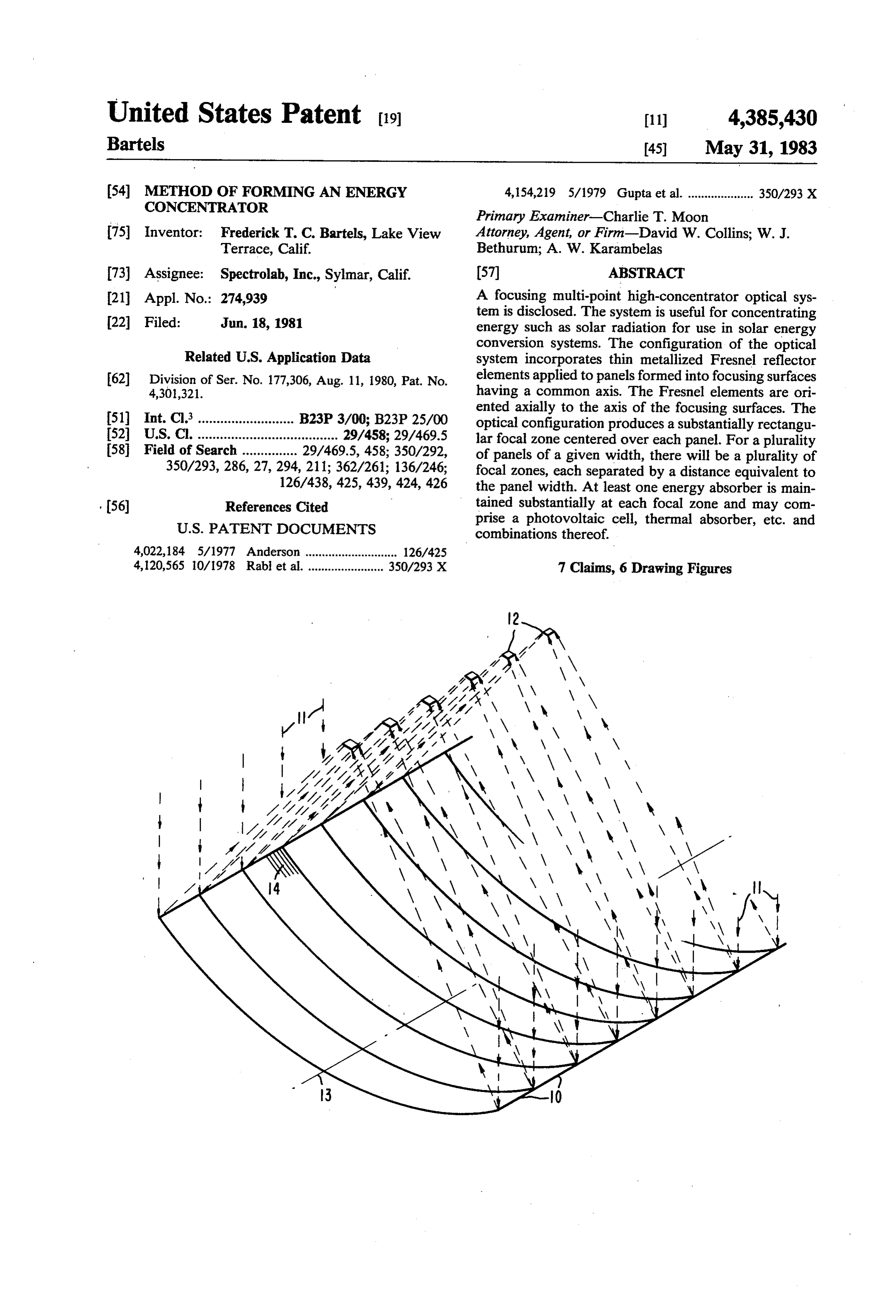
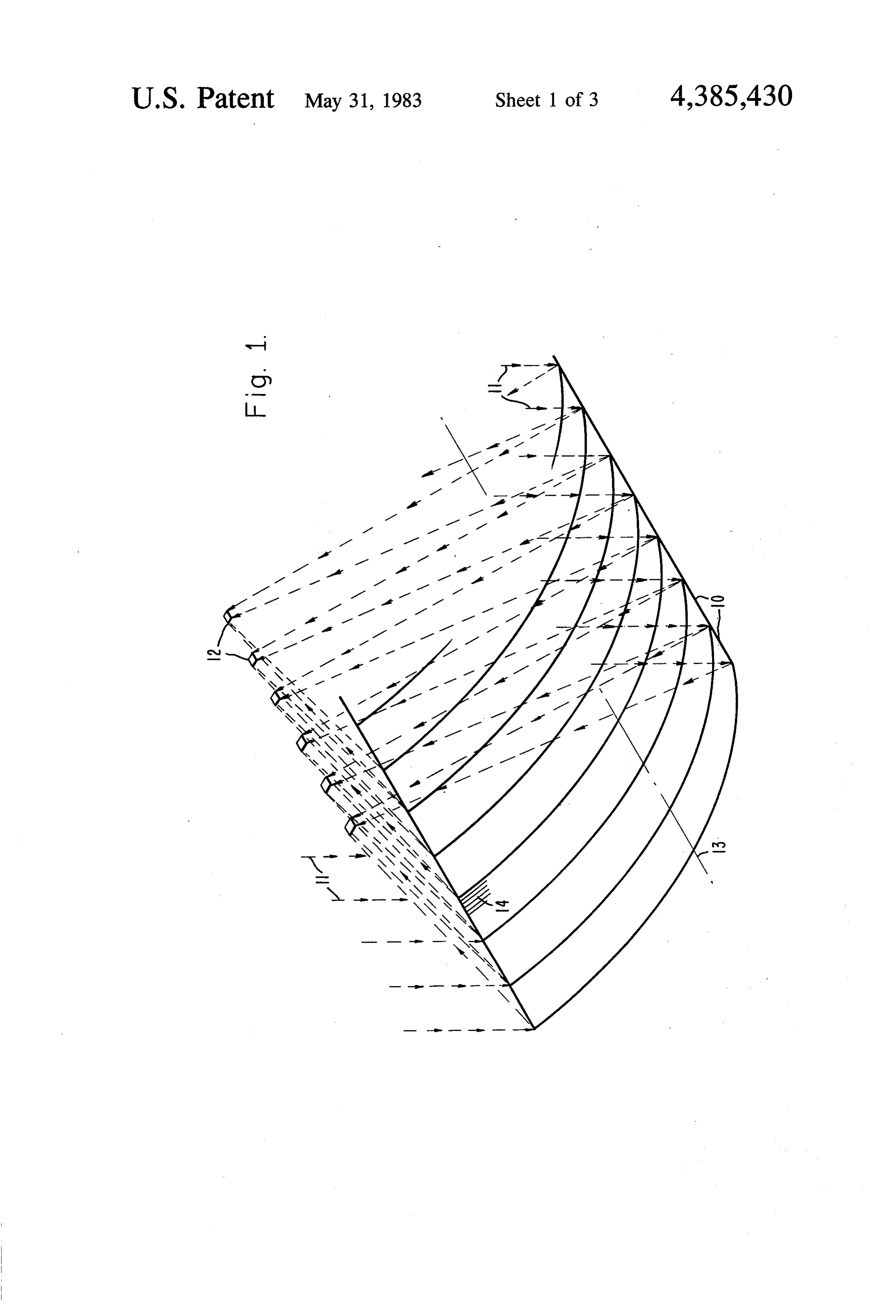
ate, the accuracy with which the curvature is formed Company (Minneapolis, MN) and are suitably em and maintained, and also the accuracy with which the ployed in the practice of this invention. reflector is maintained normal to the direction of the The bending of a linear Fresnel mirror element or incident energy in the "length' dimension, need not be reflector into a focusing surface provides focusing in great. In an important specific embodiment, if the con two principal planes. The curvature of the element itself centration ratio in one axis is quite small (e.g., five), that provides focusing in one principal plane. Focusing in axis need not be tracked continually if seasonal adjust the orthogonal plane is provided by the Fresnel reflec ment is provided. tor element as a result of the geometric surface it ap Achievement of substantially higher concentration proximates. Consequently, a substantially rectangular ratios than can be achieved by a conventional linear 10 focal zone is generated rather than a line focus. The Fresnel reflector can be obtained through the means precise curve of bending which provides optimum fo disclosed herein, with a very modest increase in cost. cusing depends on the desired concentration ratio, and Note also that the dimensions of the focal zone are is intermediate a circle and a parabola; i.e., elliptical. related to the corresponding dimensions of the reflector FIG. 1 depicts in perspective a plurality of panels 10 by the concentration ratios associated with each axis. 15 comprising at least one Fresnel reflector element for By suitable choosing reflector dimensions, focal length reflecting and concentrating incident radiant energy 11. and curvature, a focal zone can be produced which Centered over each panel is a discrete, substantially varies from a long, narrow rectangle to a near-circular rectangular focal zone 12. It will be noted that the dis spot. Thus, this invention provides means by which the tance between focal zones for each panel is equivalent configuration of the focal zone can be adapted to the 20 to the width of each panel. More than one Fresnel re requirements of the absorber element, over a wide flector element may be employed to form a panel, pro range of dimensions and configurations. viding the focal zones of all elements forming the panel are substantially aligned.
BRIEF DESCRIPTION OF THE DRAWING Each panel 10 is curved about a common axis 13 to FIG. 1 is a perspective view, partly schematic, of an 25 form a focusing surface. The segments of grooves 14 of array of concentrator panels of the invention; the Fresnel reflector elements are aligned substantially FIGS. 2a-c are cross-sectional views of a Fresnel perpendicular (axial) to the axis of the focusing surfaces. mirror assembly useful in the practice of the invention; For clarity, only a portion of the grooves is depicted. FIG.3 depicts a mounted array of solar concentrator As described above, the combination of curved focus panels; and 30 ing surface and Fresnel reflector segments generates a FIG.3a is an enlarged view of a cross-section portion substantially rectangular focal zone. The rectangular of FIG. 3 along 3a-3a. focal zone can be more effectively utilized by rectangu
DETAILED DESCRIPTION OF THE
lar groups of solar energy absorber cells than can a line focus.
INVENTION 35 The panel can be of any length suitable for the appli The description which follows below is given gener cation, since the Fresnel portion can be repeated along ally in terms of a solar concentrator and its fabrication. its length to produce multiple foci 12, as shown in FIG. However, it will be understood that the apparatus and 1. -
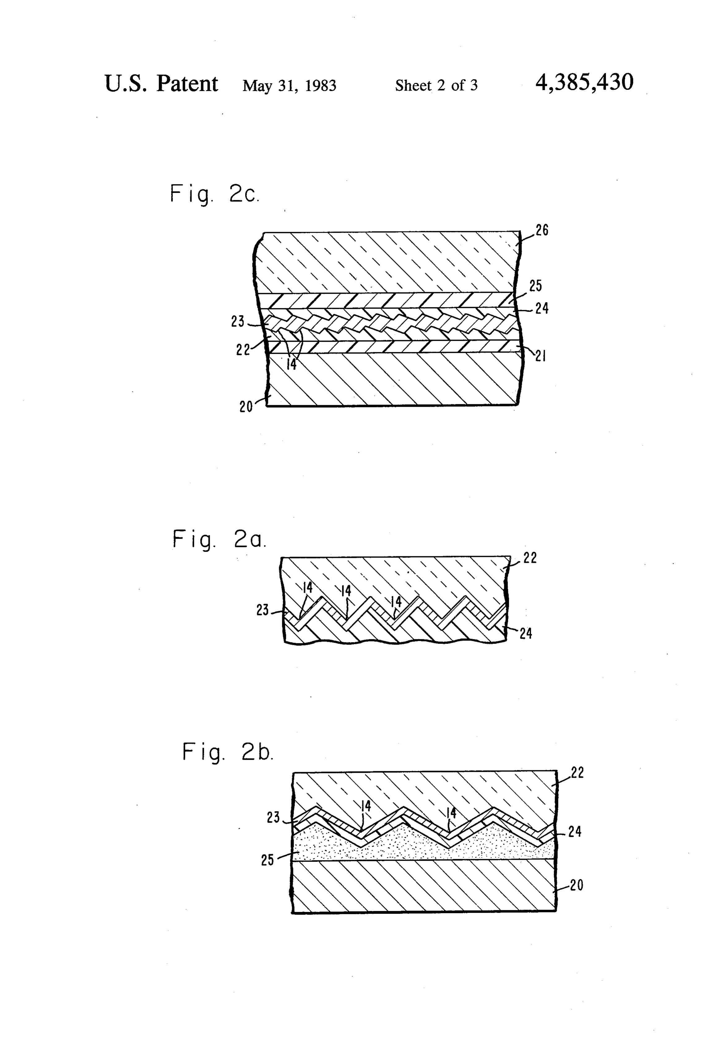
method of the invention may be used, with appropriate FIG. 2 shows cross-sectional views (not to scale), simple modifications, to concentrate energy from a normal to the grooves 14, of examples of a reflector variety of radiant sources such as infrared, microwave, panel useful in the practice of the invention. etc., and for a variety of applications. The simplest reflector panel containing all essential The energy concentrator of the invention includes elements of the invention is shown in FIG. 2a. This one or more panels comprising at least one Fresnel panel comprises a sheet of optically transparent material reflector element per panel capable of generating a 45 22 with the Fresnel grooves 14 formed in one surface. substantially rectangular focal zone, arranged such that The radiation is incident upon the un-grooved surface, the focal zones of multiple elements are substantially and the grooved surface is coated with a reflective layer aligned, each panel curved about a common axis to 23, which may in turn be coated with a protective coat form a focusing surface. By focusing surface is meant a ing 24.
surface which provides a zone to which rays converge, 50 In the panel design shown in FIG. 2a, the transparent and includes parabolic, elliptical, spherical and hyper sheet must be thick and rigid enough to maintain the bolic surfaces, combinations of these, and other curved required curvature under the environmental conditions surfaces. of service. It will usually be found that a lower cost and A Fresnel reflector element, as is well-known, com more satisfactory alternative design can be achieved by prises a reflecting surface made up of segments that 55 utilizing a thinner sheet of transparent material sup approximate a curved surface. The segments may be ported by a substrate, which may be metal or any other planar or curved. The segmented construction provides material having suitable mechanical properties. A de the optical performance of a thick element in a thin sign of this form is shown in FIG. 2b. This design differs sheet, thereby reducing cost. The type of Fresnel reflec from the simpler design of FIG. 2a in that a supporting tor utilized in the practice of the invention is a "linear' substrate 20 has been added, and the Fresnel reflector Fresnel in which the segments are formed by parallel assembly 22, 23, 24 is bonded to this substrate with an grooves in a transparent sheet. A suitable Fresnel reflec adhesive layer 25.
tor may be formed in a variety of transparent plastic In the design shown in FIG.2b, the upper surface of materials by casting, molding, extruding or embossing the transparent sheet 22 is exposed to environmental processes, followed by metallization of the grooved 65 attack, and in many applications it will be found that the surface by well-known methods. Acrylic Fresnel strips, plastic materials which are the most satisfactory choice with approximately 50 segments or grooves per inch, for this design element are insufficiently resistant to are commercially available, for example, from 3M environmental attack to provide the desired service life.
Page 7
In this case a still more complex design may be chosen, electrically isolates the cells from the conduit. Fasten as shown in FIG.2c. In FIG.2c, the reflector assembly ing means 48 is used to assemble the apparatus and is comprises a substrate 20, bonded to which by an adhe electrically insulated from metallic substrate 46 by insu sive 21 is the Fresnel reflector 22 having grooves or lation 49.
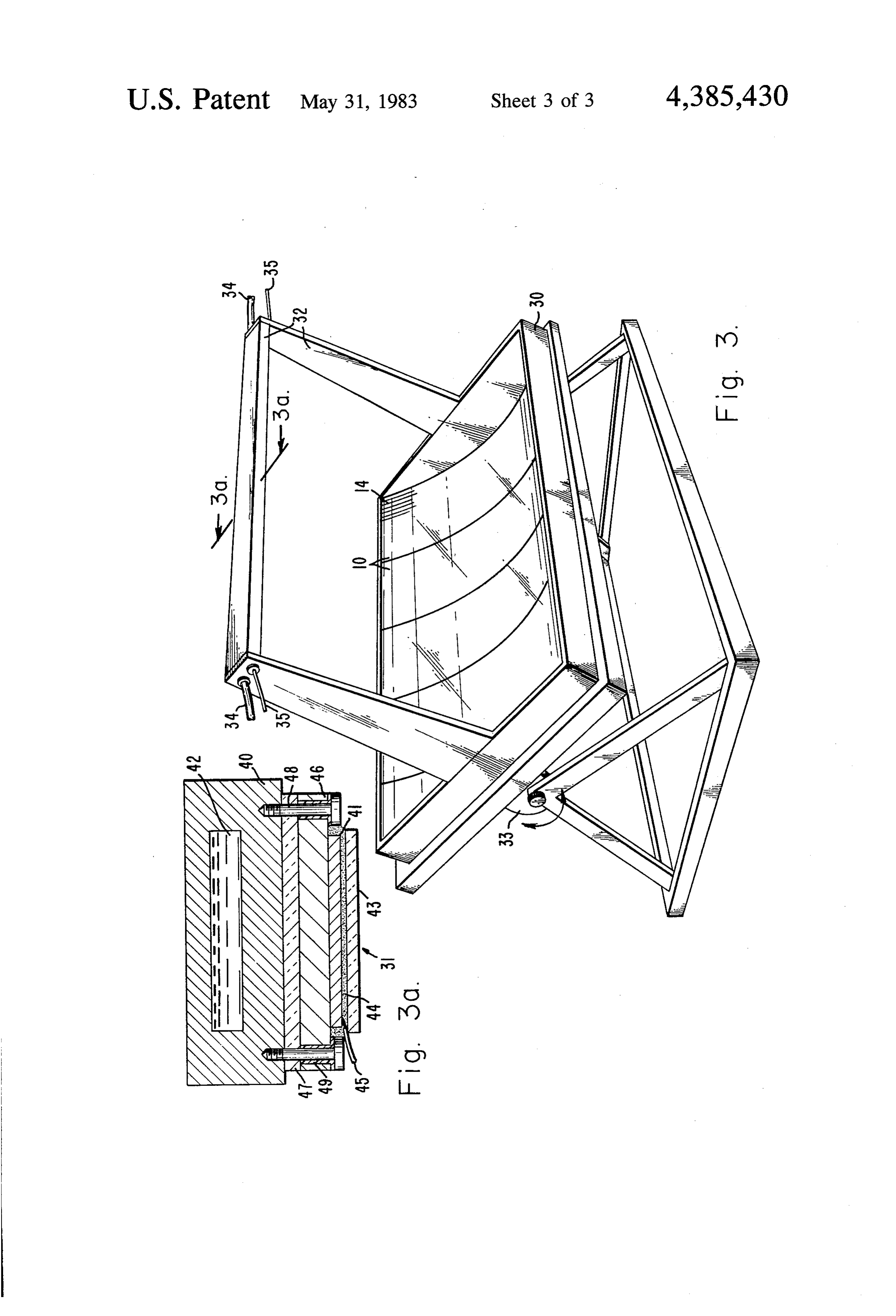
segments 14 as described above. The substrate, which Referring to FIG. 3, external connections 34 provide may be an aluminum sheet, e.g., 0.060 inch thick, for recirculating the liquid through a thermal absorber, supplies the necessary flatness and support for the Fres while electrical connections 35 provide output voltage nel reflector. A reflective layer 23 is applied to the from the solar cells.
Fresnel reflector and is protected by coating 24. A glass The various radiant energy adsorbers mentioned sheet 26 is bonded to the protective coating by adhesive 10 above are all well-known and hence do not form a part 25 to provide further environmental protection for the of the invention. By further elaboration of the designs, assembly. An example of a suitable glass is Code 0313, involving the combination of optical elements con available from Corning Glass Works (Corning, NY). structed in accordance with the teachings of the inven The reflective layer 23 may be any highly reflecting tion with other well-known elements, the energy con material. For highest reflectivity, the reflective layer is 15 centrator described herein may be adapted to a wide silver; it provides a 6.2% reflectance increase over alu variety of applications, as will be readily recognized by minum, which may also be used. The reflective layer is conveniently vacuum-deposited on the linear Fresnel those energy skilled in the art. The overall performance of an concentrator constructed in accordance with substrate (layer 22) and substantially replicates grooves this invention can most accurately be determined by
An acrylic sheet with linear Fresnel grooving 14 ray-tracing methods, which are well-known to design ers of optical systems.
conveniently serves as the reflector 22; however, glass What is claimed is:
and polymers which are environmentally stable and are 1. A method of forming an energy concentrator con compatible with the reflective layer may also be em prising:
ployed. Note that in this design the reflector 22 has been (a) bending a panel to form a concave focusing surface
inverted, so that it is no longer necessary that it be curved about an axis, at least a portion of whose optically transparent. concave surface includes at least one Fresnel reflec Before bonding to the glass, it may be desirable to tor element, the grooves of which Fresnel reflector protect the reflective layer 23 from the adhesive layer 25, especially if the reflective layer is silver. A suitable 30 dicular toarethe element so arranged as to lie substantially perpen axis of said focusing surface, thereby coating comprises a layer 24 of Vistar protective silicon generating a substantially rectangular focal zone; finish sprayed over the silver and is available from (b) supporting at least one panel such that the axis at Dow-Corning (Midland, MI) under the designation each focusing surface is substantially aligned to form Q9-6503. The various layers comprising the assembly may be bonded together by a variety of processes well 35 a common axis, the at least one panel being supported known in the art; a particularly convenient choice is in a position to intercept and reflect incident radiant vacuum lamination. energy; and
FIG.3 depicts an array of curved panels, each com (c) supporting at least one energy absorber at substan prising at least one Fresnel mirror element 10, sup tially the focal zone of each panel. ported on support means 30. A portion of segments or 2. The method of claim 1 in which the concentrator is grooves 14 is depicted. A substantially rectangular focal formed and supported so as to intercept and reflect solar zone (not shown) is associated with each panel. At least radiation.
3. The method of claim 2 in which the at least one one radiant energy absorber 31 (FIG. 3a) is operably associated with each panel, maintained in place by sup energy absorber are selected from the group consisting port means 32. The array may be moved by means 33 on 45 of photovoltaic cells and thermal absorbers. one or two axes to track the sun, employing well-known 4. The method of claim 1 in which the at least one technology. panel are formed as surfaces chosen from the class of Each absorber is maintained substantially at the focal conic sections.
zone, thus receiving solar radiation reflected from and 5. The method of claim 1 in which the at least one concentrated by the panel. The radiant energy absorber 50 Fresnel reflector element are formed by bonding a Fres may be any of those commonly known in the art such as nel surface to a compliant substrate, coating the Fresnel photovoltaic cells, thermal absorbers and the like, and surface with a reflective material and bonding a trans combinations of these. parent protective surface thereto. For example, as shown in FIG. 3a, which is an en 6. The method of claim 5 in which the Fresnel reflec larged portion through section 3a-3a of FIG.3, a high 55 tor elements comprising a Fresnel surface and a back heat conducting conduit 40, e.g., copper, provides sup are formed by coating a Fresnel surface with a metal port for solar photovoltaic cells 41, as well as conduct selected from the group consisting of silver and alumi ing heat to a liquid 42 which is used to extract heat, num, bonding the back to a compliant sheet of alumi which may be further utilized by well-known means num and bonding a transparent, compliant sheet of glass (not shown). A glass cover 43 and encapsulant 44 pro to the Fresnel surface.
tect the solar cells. The encapsulant is substantially 7. The method of claim 6 in which the Fresnel surface transparent over the radiation range of the solar cells. is coated with silver, which is in turn coated with a Electrical contact is made to the front of the solar cells protective layer prior to bonding the sheet of glass by means 45, such as conducting wire, and to the back thereto. s by means 46, such as a metallic substrate. Layer 47 65
Provenance
- Collection
- Cited prior art
- Original PDF
- patentimages.storage.googleapis.com →
- Filed
- 1981-06-18
- Pages
- 7
- Method
- pdftotext (the PDF's own text layer) + pdftoppm 300dpi page scans
- Source
- Google Patents bibliographic record
- Granted
- 1983-05-31
- Inventors
- Frederick T. C. Bartels; Spectrolab Inc
- Transcribed from
- patentimages.storage.googleapis.com →