patent · US4182662
Method of forming hydrogen
8 January 1980
Page 1 — bibliographic record
United States Patent (19) (11) 4,182,662 Hart 45 Jan. 8, 1980 54 METHOD OF FORMING HYDROGEN (56) References Cited
75 Inventor: Thomas G. Hart, Royal Oak, Mich, 3,336,209 8/1967 Hirschberg .......................... 204/128 73) Assignee: Energy Development Associates, Inc., 3,458,41 7/1969 Grotheer et al. .................... 204/128 Madison Heights, Mich. Primary Examiner-R. L. Andrews
Attorney, Agent, or Firm-Meyer, Tilberry & Body (21) Appl. No.: 925,980 57 ABSTRACT 22 Filed: Jul. 19, 1978 A method of forming hydrogen by electrolysis in a cell containing a hydrohalic acid produced from a reaction 62) Division of Ser. No. 86,258, Oct. 18, 1979, and a process using carbon particles as an input energy source division of Ser. No. 56,915, Jul. 12, 1979. wherein the acid for electrolysis is produced by react 51) Int. Cl? .......................... C25B 1/00; C25B 1/02;
ing the electrolysis separated halogen with water and
carbon particles in a reaction area communicated with 52) U.S. C. .................................... 204/101; 204/128; the electrolysis cell. The reaction can also be made in
the presence of a catalyst.
58) Field of Search ....................... 204/128, 129, 101; 24 Claims, 6 Drawing Figures
Page 2
Drawing sheet — no readable text.
Page 3
Drawing sheet — no readable text.
Page 4
Drawing sheet — no readable text.
Page 5
Drawing sheet — no readable text.
Page 6
Drawing sheet — no readable text.
Page 7
METHOD OF FORMING HYDROGEN cept can be employed for the production of commercial quantities of hydrogen with an overall efficiency here
This application is a patent application to a divisional tofore not obtainable. As will be described with respect application filed on Oct. 18, 1979 for Method of to the present invention, the invention involves the Forming Hydrogen, Ser. No. 86,258 and a divisional concept of employing the electrolysis of the halogen application filed Jul. 12, 1979 for Method of Forming acid in combination with a method of producing the Hydrogen, Ser. No. 56,915. acid in an efficient manner, which results in a sufficient The present invention relates to the art of forming quantity of the acid created at a low cost factor. The hydrogen and more particularly to a method of forming process is performed in a unit or device involving both hydrogen by electrolysis of a halogen acid produced in 10 the electrolysis cell and the acid forming reaction area accordance with a novel concept utilizing carbon, such which may be in the electrolysis cell itself or communi as coke or coal. cated therewith by conduits through which the halogen The invention is particularly applicable for an elec acid for the electrolysis process is circulated in liquid or trolysis process employing hydrochloric acid or hydri gaseous form.
odic acid, and it will be described with reference 15 In summary of the background, the present invention thereto; however, it is appreciated that the invention relates to an improvement in producing hydrogen by has broader applications and may be used with hydro employing the halogen acid electrolysis concept with a bromic acid. The use of the process with the fluorine novel interacting and combined halogen acid producing acid would electrochemically be appropriate; however, concept.
because of the highly active nature of fluorine, this 20 THE INVENTION particular halogen is not preferred. Also, the process can be used in a gas mode. In accordance with the present invention, the elec
BACKGROUND OF INVENTION
trolysis cell for separation of hydrogen from a halogen acid incorporates a reaction area in which the acid is
The production of hydrogen is becoming quite desir 25 formed using the halogen released by the electrolysis able since hydrogen has beneficial aspects as a direct process. In accordance with the broadest aspect of the heating fuel or as a means for generating electrical en invention, the reaction area is adjacent the halogen ergy in a fuel cell. Consequently, substantial efforts collecting area of the electrolysis cell and uses the halo have been devoted to obtaining large volumes of hydro gen released by the cell, water and a reaction agent for gen for subsequent use in heat or electrical energy gen 30 creating additional halogen acid. When the acid is in eration. At this time, the most common method of pro solution, the solubility of the released halogen in the ducing hydrogen is electrolysis of water, which con acid solution together with the hydrogenation effi sumes a substantial amount of electrical energy since it ciency of the present invention contributes to efficient requires over 2.0 volts D.C. for decomposition. As is replenishing of the halogen acid for subsequent electrol well known, the higher the voltage necessary for elec 35 ysis to produce hydrogen.
trolysis, the higher the electrical energy cost for the In one aspect of the invention, the reaction zone for process. To reduce the cost of production of hydrogen, creating additional acid for the electrolyte solution uses most efforts have been directed toward modifying the water and the disassociated halogen to create additional water electrolysis process in a manner to reduce the halogen acid. This chemical reaction requires rapid voltage required for the hydrolysis and, thus, the elec hydrogenation which is obtained, in accordance with trical energy required. For instance, it has been sug one aspect of the invention, by using a catalyst such as gested that high pressure water electrolysis cells can be graphitized carbon, ruthenised titanium or platinised developed which will reduce the voltage from slightly titanium. These three catalysts are effective for hydro over 2.0 volts to the general range of about 1.6-1.7 genation to a certain acid concentration level which is volts. Still, the production of hydrogen by the electrol 45 approximately 5% for hydrochloric acid. In accordance ysis of water will involve a substantial electrical energy with the preferred embodiment of the invention, the input which will continue to render hydrolysis of water reaction in the reaction area of the method involves the for the production of hydrogen an expensive process use of ungraphitized carbon which enters into the even though it may be commercially feasible in view of chemical reaction to produce additional halogen acid the versatility of the generated hydrogen. 50 and creates carbon dioxide as a by-product. This ungra The present invention relates to a novel method of phitized carbon, which is used in the preferred embodi producing hydrogen by electrolysis in a cell using a ment of the invention, allows the hydrogenation of the halogen acid such as hydrochloric acid, hydrobromic disassociated halogen beyond relatively acid concentra acid or hydriodic acid. In this manner, the electrolysis tions which are obtainable by the catalyst conceptem voltage can be reduced and the required electrical en 55 ployed in the present invention. The preferred embodi ergy for the electrolysis process can be made lower than ment employs a solution of halogen acid; however, a even the proposed improved processes for water elec gaseous process can be used. The liquid process will be trolysis. hereinafter explained. The halogen acid as used herein is The electrolysis of halogen acid to produce hydrogen hydrohalic, i.e. no combined oxygen. and the constituent halogen is a well known technol The present invention involves the method of form ogy. This concept is shown in U.S. Pat. Nos. 603,058; ing hydrogen by the electrolysis of the halogen acid in 1,746,542; 3,236,760; 3,242,065 and 3,756,930. The pres a solution, which method includes also the use of a ent invention does not involve, as a novel feature, the reaction zone in which the halogen acid is replenished concept of obtaining hydrogen from the electrolysis of by reacting dissolved, electrochemically released halo the halogen acid; however, the invention relates to this 65 gen with water in the presence of a catalyst or in the general field and develops a novel method wherein this presence of ungraphitized carbon. The latter preferred electrolysis process can be used for economic creation aspect of the method allows higher concentrations of of hydrogen at a cost substantially below the cost of the halogen acid by producing hydrogenation at con water electrolysis. Consequently, the invention relates centration levels greater than the catalyst method and to a method wherein the halogen acid electrolysis con substantially greater than other known processes for
Page 8
obtaining halogen acid by reaction of a halogen directly ducing hydrogen from water or water and carbon, pref. with water. Thus, the present invention requires only erably ungraphitized carbon. the use of water to maintain the continuous operation of In one aspect of the present invention, there is pro the hydrogen forming method. In the preferred embodi vided a method of forming halogen by electrolysis of ment water and ungraphitized carbon is used to increase the halogen acid produced from a reaction process the concentration of the halogen acid and thus the effi using electrically released hydrogen dissolved in the ciency of the total electrolysis process. As can be seen, solution. This method involves providing an electroly by using the present invention, hydrogen is released for sis cell with a hydrogen electrode in a hydrogen collec use exterior of the cell. Only water or water and carbon O tion area of the cell and a halogen electrode in a halogen must be introduced into the cell. The electrical working collecting area of the cell. A solution of halogen acid is voltage of the cell is substantially less than an electroly provided in the cell to form a liquid electrolyte with a sis cell used in the electrolysis of water. Consequently, known total working voltage. A continuous process is by using only water as the input material hydrogen is used for producing the halogen acid of the electrolyte obtained at an electrical efficiency not obtainable in a 15 used in the solution. This continuous process involves cell which produces hydrogen by direct electrolysis of dissolving the electrically released hydrogen of the water. In the present invention, the water is first con halogen electrode into the halogen acid solution at the verted into the halogen acid which is then efficiently halogen collecting area and reacting the dissolved halo converted into hydrogen and the halogen, which halo gen in a reaction area adjacent the halogen collecting gen is dissolved back into the electrolyte within the cell area with the solution water of the electrolyte and in the itself, reacts with water in the presence of the stated 20 presence of a catalyst selected from a group of graphi catalyst or ungraphitized carbon to again convert the tized carbon, ruthenised titanium and platinised tita water into the more efficiently decomposed halogen nium or ungraphitized carbon. This reaction creates acid solution. hydrogenation of the dissolved halogen within the elec This novel method which will be described hereinaf 25 trolyte solution to replenish the acid of the solution by ter in detail and defined in the appended claims hereof is the addition of only water or water and carbon. In the not suggested by the known prior art. Production of a preferred embodiment, the carbon particles are ungra halogen acid, such as hydrochloric acid, by heated car phitized carbon, such as coke. By using the dissolved bon and water is illustrated in U.S. Pat. Nos. 1,229,509; halogen in the electrolyte the electrolyte and the dis 1,420,209; 1,485,816; 1,695,522; 1,843, 196; 1,843,354; 30 solved halogen can be circulated through the reaction 1,870,308; and 2,238,896. None of these patents suggest zone to produce a total unit wherein the continuous a method for producing hydrogen, nor the concept of addition of water or water and coke allows continuous using carbon particles in a reaction zone of an electroly production of hydrogen by the electrolysis process. sis cell to produce a halogen acid by using the released The primary object of the present invention is the halogen. The present invention relates to the concept of 35 provision of a method of producing hydrogen by elec obtaining hydrogen from water without the direct elec trolysis, which method requires a less working potential trolysis of the water itself. U.S. Pat. No. 3,995,016 sug than the hydrolysis of water.
gests a method of producing hydrogen from water Another object of the present invention is the provi wherein water vapor and iodine vapor is reacted to sion of a method as defined above, which method uti form hydrogen iodide which is then decomposed into lizes a dilute solution of halogen acid into which acid hydrogen and iodine. This process reacts water vapor the released halogen of the electrolysis process can be and iodine vapor in an initial step. The present invention dissolved for replenishing the halogen acid of the elec relates to an electrolysis process wherein a solution of trolyte in a connected reaction zone by the addition of halogen acid is employed for the electrolysis process, water or water and carbon.
which process is not suggested by this prior process of 45 Still a further object of the present invention is the producing water and hydrogen from water using io provision of a method as defined above, which method dine. Another method of producing hydrogen and oxy can be used to convert coke and water to hydrogen by gen from water without the electrolysis of water is an electrolysis concept.
illustrated in U.S. Pat. No. 4,069,120. In this patent, the These advantages, the advantages discussed in rela halogen and water is combined as gas which is radiated 50 tion to the prior art and other advantages, which will be to form the hydrogen halide. Again, this process does apparent from the following description of the present not relate to the use of the disassociated halogen in an invention, illustrate the advance in the art realized by electrolysis process for recreating the depleted electro the present invention when producing hydrogen. lyte acid. Also, no reaction zone employing a reaction BRIEF DESCRIPTION OF DRAWINGS
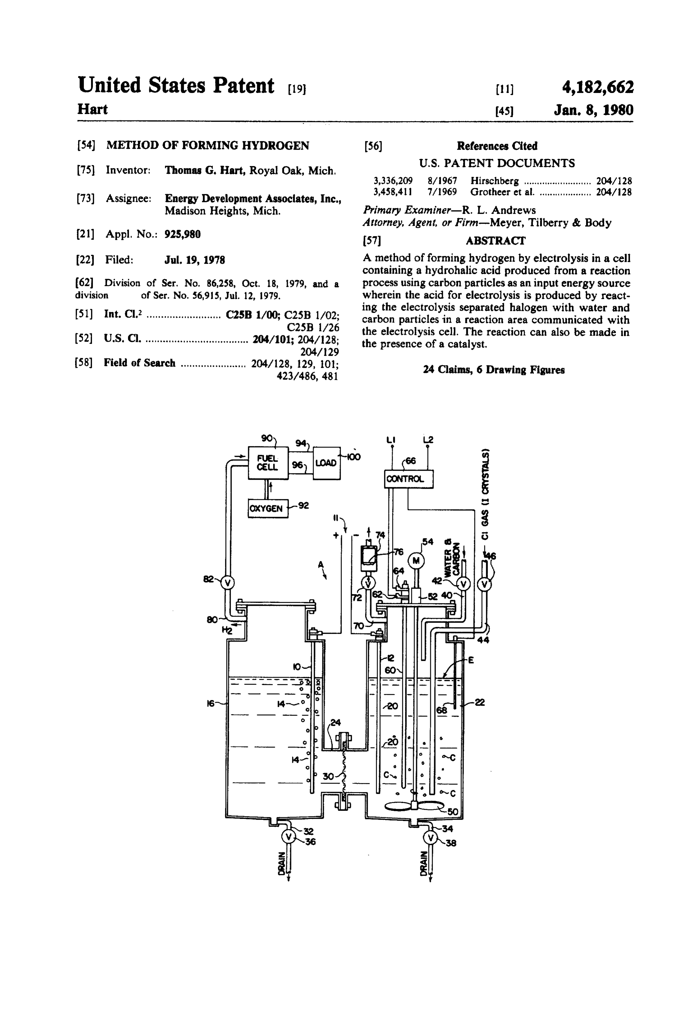
U.S. Pat. No. 4,021,323 relates to a system for pro FIG. 1 is a schematic illustration of the apparatus for ducing hydrogen by the electrolysis of hydrogen io performing the method constituting the present inven dide. In this arrangement, the hydrogen iodide is re tion.
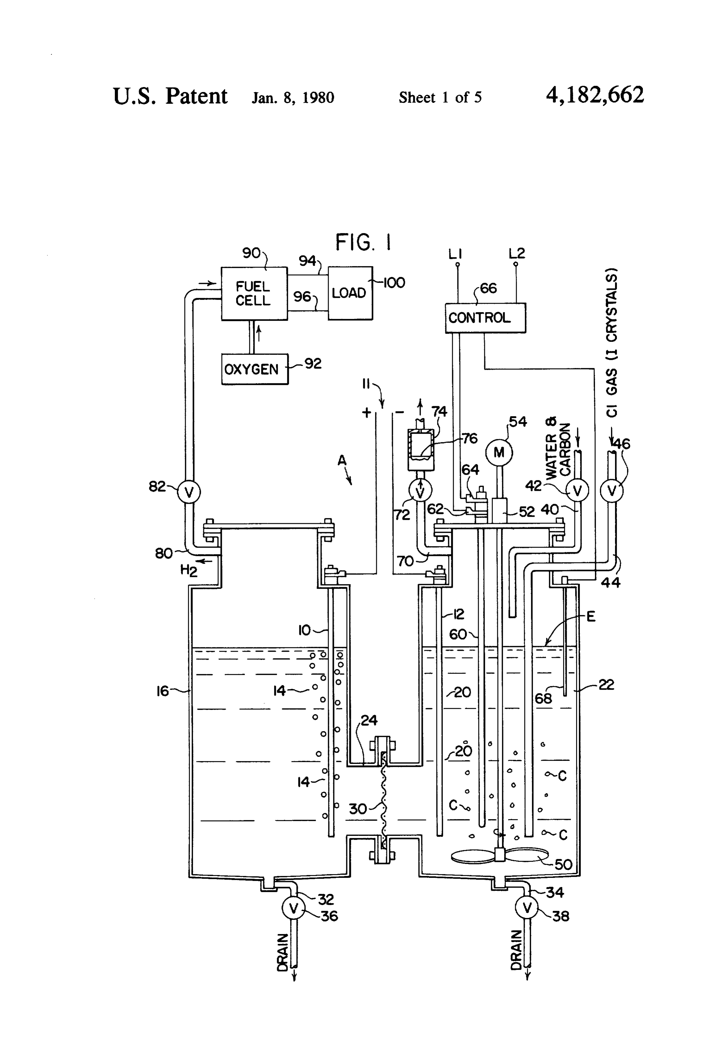
placed by a chemical reaction with the released hydro FIG. 2 is an acid concentration graph illustrating a gen and iodine in a water solution. The iodine is not characteristic of certain materials used in the reaction dissolved in the electrolyte, which is then continuously zone or area of the method constituting the present replenished by reacting the dissolved iodine with water invention;
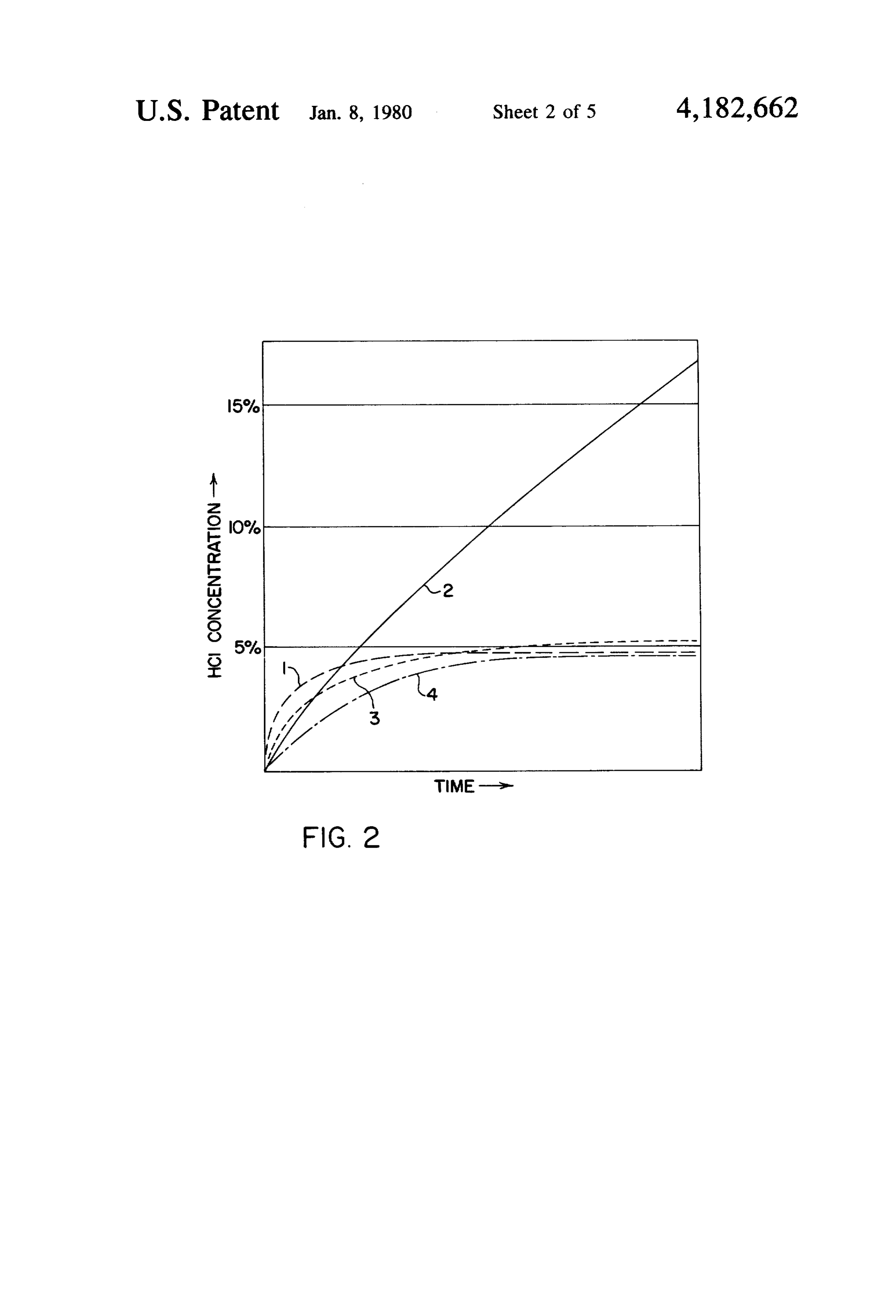
in the presence of carbon or a catalyst as disclosed in the FIG. 3 is a graph illustrating the over-voltage charac present invention. teristics of ungraphitized carbon compared to graphi The prior art described in conjunction with the basic 65 tized carbon which is theorized as the reason ungraphit aspects of the present invention is incorporated herein ized carbon will allow a substantially higher hydroge as background information and to show the novelty of nation of the halide dissolved in the electrolyte of the the simplified method of the present invention for pro present invention;
Page 9
FIG. 4 is a schematic view illustrating a more de carbon particles C react with the water to form carbon tailed arrangement for performing the method consti dioxide which accumulates in the upper portion of com tuting the preferred embodiment of the present inven partment 22. Since the carbon dioxide is substantially tion; insoluble in the electrolyte E, an appropriate vent 70 is FIG. 5 is a schematic view illustrating a system for provided to allow escape of the carbon dioxide through using the present invention in a gaseous mode; and, a one-way check valve 72 connected to a water trap 74 FIG. 6 is a schematic view illustrating the use of a containing a body of water 76. This body of water ab feature of the invention for stripping chlorine. sorbs and dissolves any halogen which may escape with the carbon dioxide through vent 70. As the concentra
PREFERRED EMBODIMENT OF THE 10 tion of halogen within the water body 76 increases, the INVENTION liquid can be drained and replaced by fresh water to Referring now to FIG. 1, there is schematically illus maintain an arrangement for separating escaping halo trated a device or cell for practicing the present inven gen from the carbon dioxide which is released in the tion of making hydrogen from water and preferably reaction compartment 22.
from water and ungraphitized carbon particles. In ac 15 Referring now to compartment 16, this compartment cordance with this illustrated embodiment, device or includes a hydrogen collection line 80 including a valve cell A includes a hydrogen electrode 10 and a halogen 82 to allow escape of hydrogen gas from compartment electrode 12 adjacent to which a halogen, such as chlo 16 for appropriate subsequent use, such as direct burn rine or iodine, is released for immediate absorption into ing or eletrical generation by a fuel cell. In the schemat the electrolyte E formed from a solution of halogen acid 20 ically illustrated apparatus for performing the method corresponding to the halogen being released at elec of the present invention, the hydrogen is used as the fuel trode 12. An appropriate power supply 11 applies a in a fuel cell 90 which is also supplied with oxygen from decomposition voltage across electrodes 10, 12 to de an appropriate oxygen source 92. In this manner, an compose the halogen acid in the electrolyte solution to electrical potential is created across leads 94, 96 of fuel produce hydrogen at the hydrogen collecting area 14 of 25 cell 90, which leads are used to power any appropriate compartment 16 and the halogen at the halogen collec load, schematically illustrated as load 10. tion area 20 of compartment 22. Compartments 16 and The cell or device A is used to electrically decom 22 are connected by an appropriate arrangement includ pose the halogen acid in the solution which constitutes ing a channel 24 separated by a membrane 30 which, in electrolyte E. The concentration of the halogen acid in practice, is formed from Nafion produced by DuPont. 30 the electrolyte is an important feature to maintain the This membrane is No. 120 Nafion and is approximately general efficiency of device or cell A. The voltage 10 mils in thickness. As is well known, Nafion is a per across electrodes 10, 12 is below the decomposition florosulfonic acid based permselective plastic material. voltage for water; therefore, the water which is used Compartment 16 includes a lower drain 32 and com with the halogen acid is not electrically decomposed by partment 22 includes a lower drain 34. Appropriate 35 the electrolysis process. Thus, the water within the valves 36, 38, respectively, are used to control the level electrolyte forms a solution of halogen acid for electrol of liquid in these compartments. These drains can be ysis of the acid. One of the features of the present inven used to remove sludge or other unwanted accumulated tion is an arrangement for increasing the concentration materials at the bottom of the respective compartments of the halogen acid within the water forming the elec 16, 22. Within compartment 22, which not only forms trolyte solution. This requires hydrogenation of the the halogen collecting area but also the reaction zone or halogen released by electrode 12, which halogen is area for producing make-up halogen acid, there is pro dissolved in electrolyte E. Thus, the halogen released vided an inlet 40 through which water and carbon parti during the electrolysis process is immediately dissolved cles C are introduced. An appropriate valve or other 45 into the solution. The dissolved halogen is then hydro metering device 42 controls the amount of carbon parti genated within compartment 22 to form additional halo cles and/or water which is introduced into the reaction gen acid for the electrolysis process. When the cell or area formed by compartment 22. At the start of the device A uses chlorine as the halogen, hydrochloric process, it is desirable to introduce halogen, such as acid is formed in the electrolyte. Because of the high chlorine, into the reaction compartment 22. This is concentration of the hydrochloric acid within the elec schematically illustrated as a halogen inlet 44 controlled 50 trolyte solution, there is an insignificant amount of hy by an appropriate valve 46. An impeller 50 is supported pochlorous acid in the electrolyte. Thus, the over-volt in compartment 22 by an appropriate journal mount 52 age or over potential associated with oxygen is not a and is driven by an electric motor 54 to maintain a liquid factor in the decomposition process between electrodes current flow outwardly and upwardly in the electrolyte 10, 12.
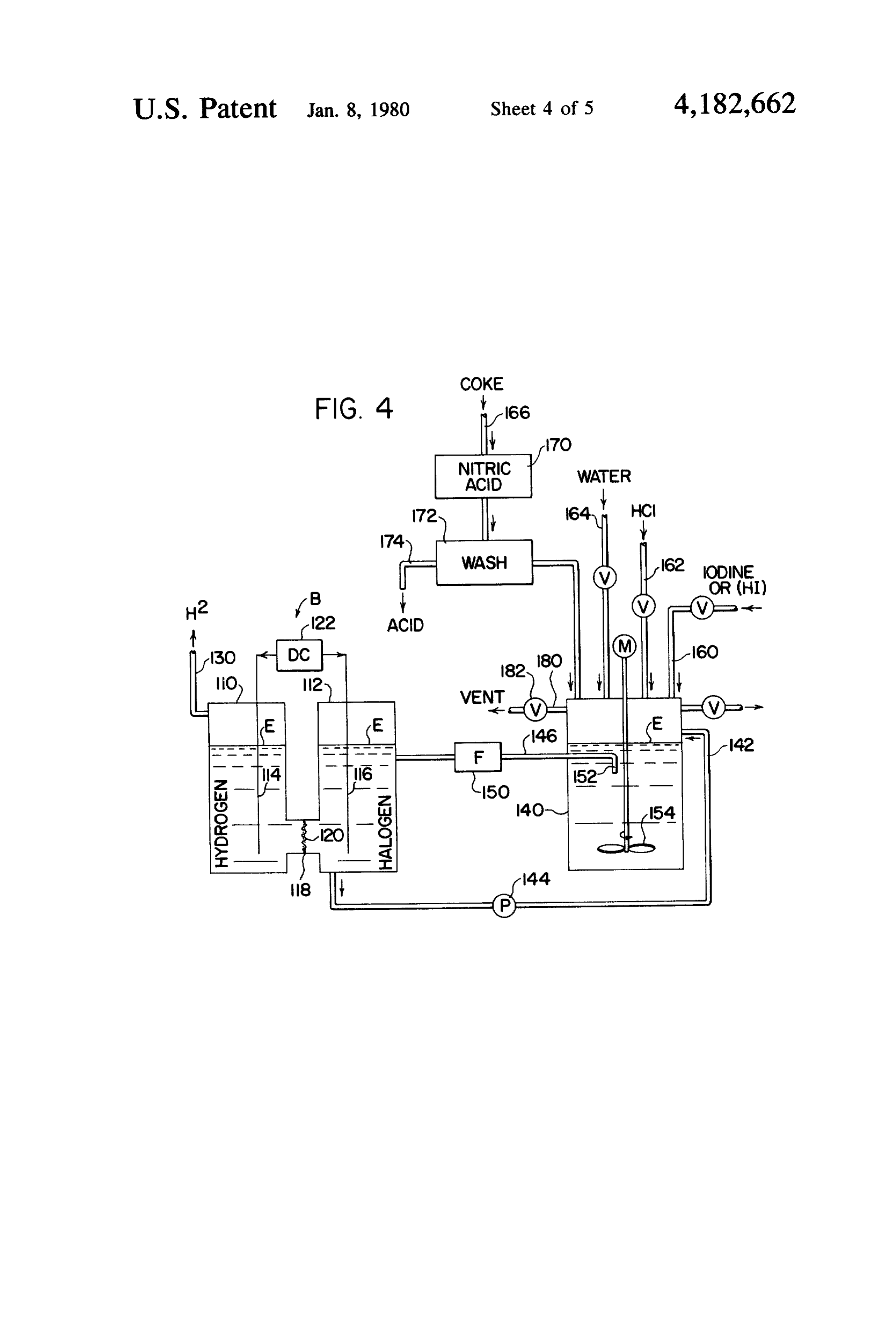
E of compartment 22. Consequently, the electolyte in 55 To increase the concentration of the halogen acid, an the reaction zone is agitated and continuously circu agent is used in the reaction area of compartment 22 to lated. This maintains the carbon particles C in suspen promote the hydrogenation of the halogen. In the pre sion within the electrolyte of compartment 22. In prac ferred embodiment as will be described with respect to tice, the electrolysis produces sufficient heat to maintain Example I, the agent is ungraphitized carbon particles the electrolyte in the reaction zone at above about 80' having a relatively small size. This carbon is oxidized to C. This temperature facilitates the chemical reaction in form carbon dioxide as previously discussed so that the area. 20. At first it may be necessary to heat the electro energy of the carbon is used in the chemical process lyte. This can be done with cal rod 60 connected across involved in the creation of the halogen acid which is terminals 62, 64. An electrical heating control 66 senses subsequently electrically decomposed in the electrolysis the electrolyte temperature by thermocouple 68 and 65 aspect of device or cell A. By increasing the hydrogena controls heating element 60. During continued use the tion of the halogen, such as chlorine, dissolved in the electrolysis heat is sufficient to maintain the level of electrolyte E, the concentration of the acid in the elec heat in the reaction zone. As previously described, the trolyte solution can be drastically increased over other
Page 10
processes wherein halogen is absorbed into water to dipped in a chloroplatinic acid solution. In FIG. 2 it is form acids. In the past, when halogen is absorbed in a noted that there is a rapid increase in the halogen acid water solution, a very low acid concentration was ob concentration in a solution containing dissolved halo tainable, i.e. below about 3%. Thus, absorption of halo gen below about 3% concentration. A very slow in gen in water to produce halogen acid was not useful for crease in concentration beyond about 5% of halogen efficient electrolysis of the resulting acid solution. It has acid was found for all the materials, except the ungra been found that chlorine, bromine and iodine can be phitized carbon. The concentration of the halogen acid continuously dissolved into the aqueous acid solution when using ungraphitized carbon is a substantially con formed by these halogens and that the dissolved halo stant rate even at the lower levels and this rate contin gens can be hydrogenated in the presence of carbon 10 ues for an acid concentration within water of up to and particles to produce make-up halogen acids at concen beyond about 20% acid in solution. Thus, a dissolved trations higher than about 3%. It was found that graphi halogen is continuously hydrogenated when using un tized carbon promotes hydrogenation of the disclosed graphitized carbon. When using the other three agents, halogen into the halogen acid solution at a rate which the hydrogenation of the halogen continues until the diminishes sharply as added acid strength increases. 15 solution reaches about 5% acid. At this point, hydroge This concept is illustrated in curve 1 of FIG. 2. Thus, in nation of the halogen essentially stops. Still, the 5% hydrochloric acid, carbon particles which are graphi concentration is higher than the hydrogenation level tized particles promote hydrogenation of the acid at a obtainable without the selected agents. Thus, any of the relatively rapid rate until a concentration is obtained, four materials as so far described and illustrated graphi which concentration is found to be approximately 5%. 20 cally in FIG. 2 can be used to increase the hydrogena Thus, graphitized carbons can be used if the concentra tion level of the absorbed halogen within an acid solu tion of the hydrochloric acid or other halogen acid is to tion used for the electrolyte in device or cell A. The be relatively low. However, higher concentration of the ungraphitized carbon is the preferred hydrogenation halogen acids produces a superior and more efficient material.
electrolysis process. It has been found that if the carbon 25 Although the reason for the continued hydrogenation particles are ungraphitized carbon, they promote the of the chlorine or other halogen beyond a low level hydrogenation of the dissolved halogen into the acid when using ungraphitized carbon is not known it is solution at a rate which does not diminish as the concen believed that this phenomenon is related to the over tration of the acid increases at least to a concentration of potential characteristics of ungraphitized carbon in a 20%-30%. This is shown in curve 2 of FIG. 2. For this 30 halogen acid solution. This concept is shown in FIG. 3 reason, the preferred embodiment of the present inven wherein the over potential or over-voltage in millivolts tion uses ungraphitized carbon. By using ungraphitized for ungraphitized carbon and graphitized carbon are carbon particles as the energy source for hydrogenation compared. This graph was constructed by using elec of dissolved halogen within electrolyte E, the carbon of trodes of graphitized and ungraphitized carbon in dif the particles is consumed to form carbon dioxide. Con 35 ferent concentrations of hydrochloric acid and measur sequently, carbon is used in the process of making hy ing the over-voltage at these concentrations. In this drogen so that the energy of the carbon is released in graph, it is noted that both the ungraphitized and graph the process. This energy is used to provide hydrogen itized carbon retain a relatively low over potential up to which has vastly superior burning and energy creating approximately 20% hydrochloric acid and this is the characteristics then the carbon. For this reason, ungra percentage of hydrochloric acid at which the hydrogen phitized carbon is preferred in the present invention and chloride commences to disassociate from the water. the invention is directed to the concept of converting Thereafter, the graphitized carbon substantially in carbon in the presence of water into hydrogen wherein creases its over potential with respect to the halogen carbon dioxide is formed as a by-product. FIG. 2 also whereas ungraphitized carbon continues on at approxi shows curves 3 and 5 which are related to the hydroge 45 mately the same over potential or over-voltage level. nation by catalysts other than graphitized carbon, Thus, the ungraphitized carbon continues to retain a within compartment 22. The catalysts used to produce relatively low over-voltage or over potential. At the these two curves are ruthenised titanium and platinised surface of the carbon particles in the present invention, titanium, respectively. As can be seen in FIG. 2, the two the hydrogenation of the halogen takes place. The con catalysts, which can be used with added water only in 50 centrations of the halogen acid at the particle surfaces is the reaction zone 22, produces a concentration of hy relatively higher than the total acid solution concentra drochloric acid or other halogen acid generally com tion because the produced acid accumulates at the reac paring to the graphitized carbon of curve 1 which acts tion surface. Consequently, the ungraphitized carbon as a catalyst. FIG. 2 illustrates that the use of ungraphit continues to hydrogenate the halogen at the carbon ized carbon as shown in curve 2 is the preferred source 55 surfaces whereas the graphitized carbon has a substan of energy for the reaction within reaction chamber 22. tially higher over potential or over-voltage at this level By using ungraphitized carbon, the concentration of the and stops hydrogenation at about 18% acid in the area halogen increases substantially to approximately 20% of the carbon surfaces. This produces an acid concen hydrochloric acid. The material used in creating the tration within the total electrolyte E of approximately curves of FIG. 2 was ATJ graphite from Union Carbide 5% whereas the capability of the ungraphitized carbon Corporation as the graphitized carbon. The ungraphit to retain a low over-voltage or over potential continues ized carbon was Grade 37 coke-carbon from Airco to hydrogenate even though the concentration of the Speer Corporation. This ungraphitized carbon is used in halogen acid at the surface of the carbon increases sub Example I as will be described later. The ruthenised stantially above the 18-20% solution or concentration titanium was prepared by the well known method of air 65 level.
heating porous titanium dipped in a ruthenium chloride The actual test recorded in FIG. 3 relates to over solution. The platinised titanium, was prepared by a voltage or over potential which is generally the voltage well known method of air heating porous titanium or potential greater than the theoretical potential to
Page 11
produce a given electrochemical reaction. To obtain the brane 120 as previously described.anAappropriate
D.C. power sup chart shown in FIG. 3 to illustrate the relationship between graphitized and ungraphitized carbon as an ply schematically illustrated as power supply 122 appl over potential factor, the over-voltage between two lies a D.C. voltage across electrodes 114, 116 which electrodes and hydrochloric acid having various con 5 voltage is in the general range of 0.6-0.7 volts D.C. This centrations was measured at the electrode. Ten milli voltage is selected to electrically decompose the hydri amps per square inch of current density was used. As odic acid within electrolyte E. Of course, this same the concentration was increased, the over potential for arrangement could be used for the other halogen such the ungraphitized carbon electrode was substantially as chlorine and bromine. A hydrogen outlet 130 directs constant at about 7 millivolts at 5% hydrochloric acid 10 hydrogen from compartment 110 to an appropriate concentration and raised in a substantially uniform man storage or using device. In this illustrated embodiment, ner to about 8 millivolts at 37% concentration of hydro a separate reaction tank 140 is provided through which chloric acid. As to graphitized carbon electrode, the is continuously circulated the electrolyte E by an ap over potential was about 5 millivolts over a range of propriate inlet 142 having a pump 144. This pump concentration of 5-18% acid within the solution. As the 5 pumps dissolved halogen and the electrolyte into the acid concentration was thereafter increased, the graphi reaction tank 140. The heat caused by the electrical tized carbon electrode used in the test shows a very decomposition process is sufficient heat to retain neces sharp over potential or over-voltage rise reaching about sary reaction temperature within tank 140. Thus, addi 45 millivolts at 24% concentration of hydrochloric tional heat is not required and the electrolyte within acid. As the hydrochloric acid was then continued to tank 140 can be heated to the boiling point if sufficient increase in percentage, the graphitized carbon showed waste heat is created by cell B. Outlet 146 directs elec an over potential of about 45-46 millivolts through acid trolyte E from reaction tank 140 to cell B through an concentrations of 24-37% concentration. This relation appropriate filter 150 which removes any unwanted ship is illustrated in FIG. 3. Thus, since the ungraphit impurities within the electrolyte as it is being circulated ized carbon electrode in the test indicated no substantial 25 back to cell B. A center intake 152 is used to collect the increase in the over potential at the electrode as the electrolyte from tank 140. Impeller 154 circulates the concentration of acid increased, it has been theorized electrolyte in tank 140 outwardly so that the carbon that when using ungraphitized carbon in the method of particles are generally spaced from intake 152 and are the present invention for the reaction particles within not directed toward filter 150. In this illustrated em compartment 22, the over potential at the carbon parti 30 bodiment of the invention, line 160 is used for introduc cle surfaces does not substantially increase even though ing iodine or HI into the tank at the start-up of the the concentration of the acid within the reaction zone process. Thereafter, make-up iodine is not generally and adjacent the surface does increase. By the experi required in the continuous operation process. A line 162 ment using graphitized and ungraphitized carbon in allows the introduction of hydrochloric acid into the hydrochloric acid as illustrated in FIG. 3, it is shown 35 reaction chamber 140. As will be described later, hydro that the ungraphitized carbon does not have a substan chloric acid has a decomposition voltage substantially tial change in over potential with respect to a halogen, higher than the hydrogen iodine or hydriodic acid and such as chlorine. This indicates that the over potential thus can be used with water within electrolyte E with of the ungraphitized carbon particles remain substan out actually entering into the electrolysis process. The tially constant in the reaction zone 22 of device or cell hydrochloric acid has an advantage which will be de A shown in FIG. 1. Thus, ungraphitized carbon is used scribed later. It reduces the voltage necessary between in the preferred embodiment of the invention with all electrodes 114,116. Any reduction in voltage is a sav the halogens such as chlorine, bromine and iodine. ings in electrical energy which thus increases the elec From the above description, the present invention trical efficiency of a device using the present invention. involves a novel means of using coal or other carbon for 45 Line 164 is used for introducing water into the reaction the manufacture of halogen acids which are electrolyti chamber 140. The purpose of the water has been previ cally decomposed into hydrogen. The by-product is ously described. In accordance with this particular carbon dioxide. The released halogen is dissolved into illustration of the invention, coke is introduced through electrolyte and then hydrogenated within the reaction line 166 and is treated by nitric acid in tank 170. There zone of the cell A to produce a continuous process 50 after, the coke particles are washed in a tank 172 and the wherein the dissolved halogen in a circulated electro residual acid is removed by line 174. Thus, the nitric lyte is rehydrogenated by the use of carbon. Since hy acid treated coke particles are introduced in the reac driodic acid has a much lower electrical disassociation tion chamber 140 in the desired amount to promote voltage than water or hydrochloric acid, this acid can hydrogenation of the iodine dissolved within electro be used in a more efficient manner than hydrochloric 55 lyte E pumped from cell B through inlet 142. An appro acid. Examples II and III relate to the use of this halo priate vent for the carbon dioxide gas is illustrated as gen acid and improvements in the method of the present line 180 having a check valve 182. Of course, a water invention as they relate to hydriodic acid. trap could be used as previously described with respect Referring now to FIG. 4, this figure is a modification to the embodiment of the cell A as shown in FIG. 1. of the preferred embodiment shown in FIG. 1 and is The general operation of cell B and its associated reac used for a halogen acid as previously described. In this tion chamber 140 is the same as the operation of device particular example, iodine is used as the halogen; how or cell A shown in FIG. 1. The advantages of using the ever, the halogen could also be chlorine. Cell B includes nitric acid washed carbon particles and hydrochloric hydrogen collecting compartment 110 and iodine col acid in an iodine process are explained hereinafter and lecting compartment 112. Within compartment 110 is a 65 used in Example III. Again, the device shown in FIG. 4 hydrogen collecting electrode 114. In a like manner, a produces hydrogen by the use of water and ungraphit halogen or iodine collecting electrode 116 is provided ized carbon particles. Of course, graphitized carbon within compartment 112. A conduit 118 connects com could be used. In the former instance, the carbon is
Page 12
consumed in the chemical process used in producing the were used as make-up ungraphitized carbon per hour. halogen acid necessary for the electrolysis process car This example produced 2 grams of hydrogen at a heat ried out by cell B. ing capacity of 264 Btu with 32 watt hours or 110 Btu EXAMPLE I input per hour of electrical energy.
A reaction or chlorine compartment of cell A had a Hydrogenation Effectiveness Factors capacity of about 500 ml and was filled with 300 ml of A study of the halogens, chlorine, bromine and io water. This fills the hydrogen compartment, which was dine, for use in the processes described in Examples I the same general size, to this same level. The hydrogen and II indicated several factors which affect the effec electrode was graphite which had been platinised by O tiveness of the processes, but not the basic theory or dipping it in chloroplatinic acid and heating it in air. operability of the processes. Hydrogenation of the halo This reduces the electrode over potential with hydro gens, even at concentrations about 3%-5%, allows the gen. In a similar manner, the chlorine electrode was system to operate effectively. The hydrogenation rate formed from graphitized carbon or graphite and was of the halogen is inversely related to the free energy of boiled in nitric acid for 30 hours. The intermediate 15 the halogen acid which is lowest for the chlorine acid membrane between the compartments was formed from and is highest for the iodine acid. Consequently, hydro DuPont 120 Nafion with a thickness of 10 mils. The genation, or acid formation, is more rapid and easily hydrogen ions pass between the chambers to establish accomplished with hydrochloric acid. However, the electrical continuity and generally uniform acid con solubility of the halogen in its respective acid is greatest centration, 20 for iodine in hydriodic acid and less for chlorine in Approximately 20 grams of powdered coke was hydrochloric acid. Taking these factors into consider charged into the reaction compartment and the water ation, certain modifications in the rate of acid formation was heated to about 80 C. The coke was standard in the coke-water-halogen system have been discov ungraphitized carbon sold by Airco Speer Corporation ered.
as Grade 37 coke-carbon. The particle size was such 25 By treating the coke with nitric acid by passing the that it passed through a standard 6 mesh screen and not coke through hot nitric acid, the rate of hydrogenation through a standard 14 mesh screen. This powder was of the halogens in the coke process is increased. The then slurried in the water and held in suspension by the increase in hydrogenation rate is a factor of about ten impeller. Thereafter, chlorine gas was introduced into for iodine and substantially less for chlorine. The reason the slurry of the reaction compartment and the HCl 30 for this action is not known; however, it is theorized concentration continued to raise to between 20%-25% that the nitric acid reduces the absorption of the halo by weight, whereas when using the same procedure gen into the coke or ungraphitized carbon, i.e. carbon with ATJ graphite from Union Carbide Corporation, which has not been heated to over about 2000 C. The ruthenised titanium and platinised titanium instead of absorption reduction appears to result in a reduced the ungraphitized coke, the concentration peaked out at 35 halogen over-potential at the carbon surface and, thus, about 5% HCl, To reach the 25% HCl, about 140 increases the rate of hydrogenation. The iodine is af grams of chlorine reacted with the 20 grams of coke to fected more by this process. In summary, one improve produce about 140 grams HCl in solution. ment in the basic method of Examples I and II is the A voltage of 1.2 volts D.C. was applied across the pretreatment of the coke particles by nitric acid. electrodes to produce about 1.0 amperes of current flow Since solubility of the halogen in its acid is important through the electrolyte. About 1.1 volt D.C. was used to ultimate hydrogenation of the invention, an improve for decomposition of the acid. Hydrogen was produced ment in solubility is advantageous. In practice this has at the hydrogen electrode and directed from the unit. been accomplished by adding sodium chloride to iodine The chlorine produced at the chlorine electrode was acid. This salt increased the rate of solubility of iodine in reused to combine with water and carbon to produce 45 hydriodic acid, but decreased this rate for chlorine in make-up HCI. Carbon dioxide was released by this hydrochloric acid. Consequently, the rate of hydroge process and was passed through water bath 76. In the nation may be adjusted by a salt, such as sodium chlo process 20 grams of water and 6 grams of the coke ride.
carbon are consumed per hour to produce 2 grams of The rate of reaction is also affected by the free energy hydrogen per hour while maintaining the acid concen 50 of the acid at the carbon surface of the particles. As tration at about 20%. previously stated, the higher the free energy, the lower After the process came on line, the heat generated by the hydrogenation rate. It has been found that this rate the 12R drop across the electrodes was sufficient to can be affected by adding acids of a lower known free maintain the electrolyte at an elevated temperature energy level to acids of higher free energy levels. For above 80 C. Heater 60 was disconnected during the 55 instance, if hydrochloric acid, having the lowest free process. Consequently, 6 grams of carbon produce 2 energy of the halogens under consideration, is added to grams of hydrogen per hour with a theoretical heating a system based upon hydrogen bromine or hydrogen capacity of 265 Btu. The electrical energy used per hour iodide, the hydrogenation rate is increased. In a like is about 66 watt-hours which converts into approxi manner, hydrobromic acid or hydrogen bromine can mately 226 Btu per hour. The electrical energy of 226 increase the hydrogenation rate of a hydrogen iodide Btu produced hydrogen with a converted heating ca system. This phenomenon apparently occurs because of pacity of 264 Btu. the free energy modification at the carbon surface. EXAMPLE II Also, these added acids are not decomposed because they require higher voltage than used for the base acid.
The same basic process as used in Example I was 65 In summary, factors such as treatment of the coke performed in cell A with hydriodic acid as the electro with nitric acid, using a solubility modifier and adding a lyte acid. In this instance the voltage was reduced to second halogen acid to the system are helpful in con about 0.6-0.7 volts D.C. and about 2 grams of coke trolling the effectiveness of the basic system described
Page 13
in Examples I and II. Sufficient solubility of the halogen Of course, other modifications could be made in the in its acid is needed to capture the released halogen at various processes illustrated in carrying out the present the halogen electrode for hydrogenation in the system. invention without departing from the scope of the in In addition, low over potential of the ungraphitized vention which relates to the concept of producing hy carbon at higher concentrations retains the hydrogena 5 drogen from the electrolysis of a halogen acid electro tion process beyond the normal lower concentrations the absorbedabsorbs lyte which the released halogen and circulates halogen with the electrolyte in a reaction obtained by merely reacting halogen with water.
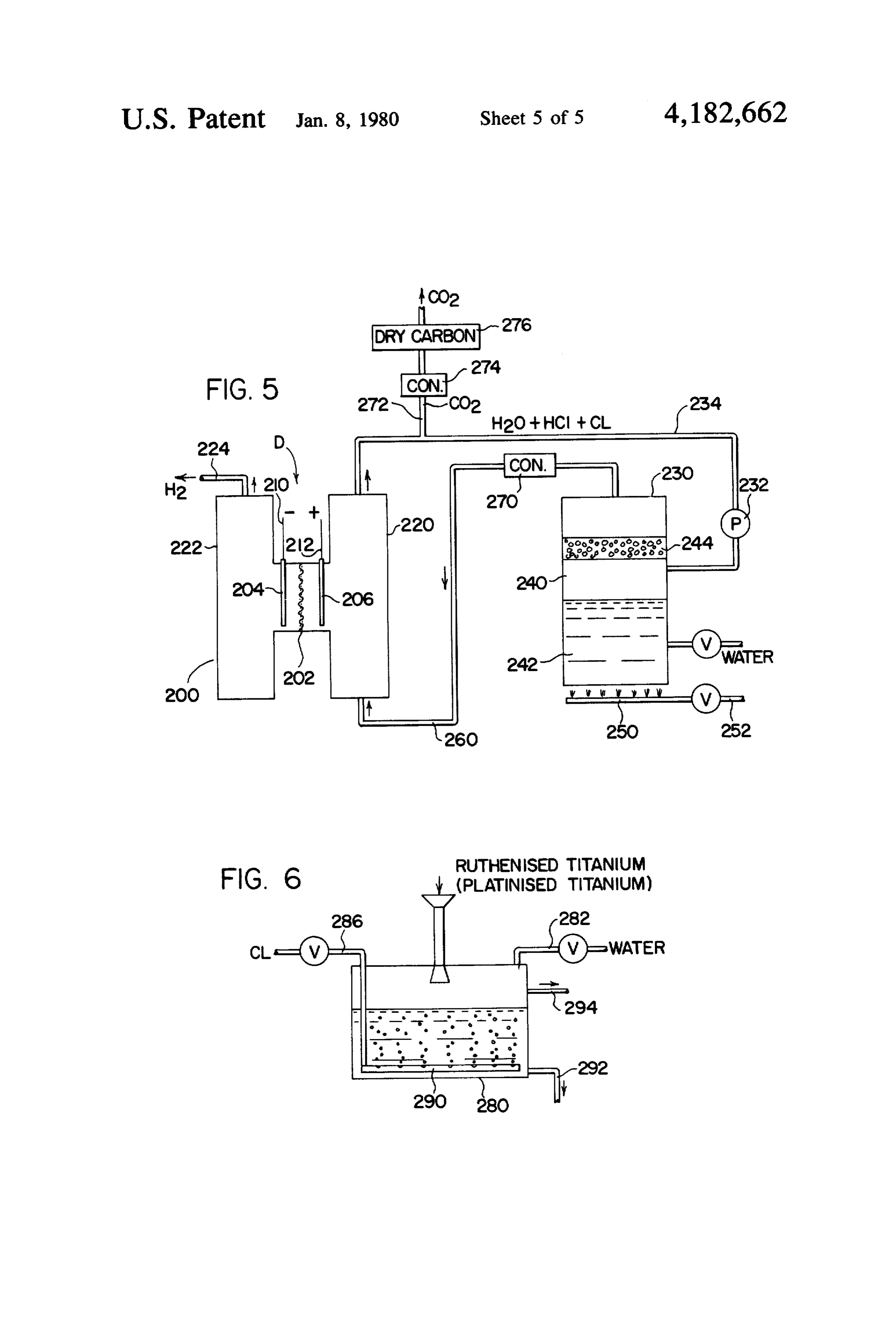
The interaction of the experimentally determined area to rehydrogenated the halogen with the use of water and water or carbon. The released hydrogen effectiveness factors for the general process of Exam 10 itself ples I and II can be manipulated to obtain process reac totallyit useful not required for the rehydrogenation and is for external purposes such as heating or tions having further improved electrical and chemical generation of electricity, to name two examples. characteristics. These factors act upon the solubility and over potential of the carbon to control and facilitate Modifications hydrogenation at higher acid concentrations, in the 15 Referring now to FIG. 5, a modification of the pre range of 5%-25% in the hydrochlorine for example. ferred embodiment is illustrated. In this embodiment the EXAMPLE III cell D includes a housing 200 with a Nafion membrane Another example was performed using the effective 202 having surface mounted electrodes 204, 206. A ness factors experimentally obtained and explained 20 210, 212 source voltage applies a working voltage across leads above. In this example the three hydrogenation rate function.soA that the membrane produces an electrolysis modification factors were used for a system similar to ous acid vapor at thecompartment halogen electrode 220 provides a gase face of the membrane to
Example II using hydrogen iodide in the electrolyte allow electrolysis to form a halogen gas in compartment solution, Hydrogen was obtained from the electrolyte 220. At the same time, hydrogen is separated formed by hydrogenation of iodine which is the pre 25 mulated in compartment 222, from which itand accu exits by ferred system of the present invention. In this example, way of conduit 224.
cell B as shown in FIG. 4 was used. The ungraphitized Disassociated halogen, in the example chlorine, is in carbon, i.e. coke, was treated with nitric acid and then gaseous form from compartment 220 to a reaction tank heated to remove excess nitric acid. This produced an or area 230 by a means represented as pump or blower increase in the iodine hydrogenation rate; however, the 30 232 in conduit 234. Vapor from conduit 234 is forced small amount of nitric acid residue on the carbon parti into chamber 240 defined by a body of water 242 and an cles exhibited no apparent deleterious effect on the total upper bed of ungraphitized carbon 244, Burners 250 in system. In this example a small amount of titanium tetra line 252 heat the water in body 242 to the boiling tem chloride was added which is a salt to further increase perature to produce water vapor. This vapor together the hydrogenation rate and reduce the corrosiveness of with the vapor from circuit 234 reacts with the carbon the acid mixture. This salt increased the solubility of the to hydrogenate the chlorine into hydrochloric acid electrode released iodine. A substantial amount of hy vapors which are carried by conduit 260 to the lower drochloric acid was used with the hydrogen iodine portion of halogen compartment 220 wherein the elec electrolyte. The hydrochloric acid lowered the decom trolysis releases chlorine for a continuous cycle. Con position voltage of the HI electrolyte; however, it did 40 denser 270 removes water vapor. The heat of the elec not enter into the electrolysis since the voltage across trolysis process maintains the vaporized condition of the electrodes was about 0.3 volts D.C. Without a sub the circulated constituents in compartment 220 and stantial amount of HCl, the voltage of the HI cell was conduit 234.
about 0.6-0.7 volts D.C. This voltage of 0.3 volts is To remove the carbon dioxide from the closed loop, sufficient to electrically decompose the HI, but, not the 45 a vent 272 having a small diameter, i.e. about 1/20th of HCl, which requires about 1.2-1.3 volts. To obtain a 0.3 the area of conduit 234, is provided in the coolest area volt decomposition voltage for the HI cell without the of the circuit. A condenser 274 condenses the water HCl additive, the HI concentration would need to be vapor which absorbs any HCl. A large volume of car about 50% HI by weight in water. In this example the bon dioxide with traces of halogen then passes from the 0.3 volt decomposition of HI electrolyte was obtained 50 condenser. A dry carbon bed 276 then removes the by 20% HCl by weight and 1% by weight HI. Conse halogen, if necessary.
quently, this example produced increased hydrogena The catalyst concept used in the present invention tion of iodine, reduction in the decomposition voltage can be used in stripping a halogen from a gas stream of HI and reduction in the amount of iodine required, since it increases the obtainable concentration of halo which is considerably more expensive than chlorine. 55 gen in water. FIG. 6 shows a system for utilizing this This example contained: aspect. A tank 280 is partially filled with water from (1) Airco Speer Grade 37 coke carbon boiled for 8 valved conduit 282. Graphitized carbon, ruthenised hours in constant boiling nitric acid washed in water, titanium, platinised titanium or mixtures thereof, in (2) 20% by weight HCl. particle form, is introduced into the water through feed (3) 1% by weight HI. line 284. A gas stream, illustrated as chlorine, is directed (4) 1% by weight titanium tetrachloride. by valved circuit 286 into a diffuser 290 at the lower (5) Remainder water. portion of tank 280. As the halogen bubbles through the The temperature of the cell was about 108 C. and the water in the presence of the catalyst, the halogen is electrolyte was stirred to prevent settling of the carbon formed into hydrohalic acid to higher concentrations particles. The decomposition voltage to produce hydro 65 than obtained by water itself. A drain 292 ultimately gen was 0.3-0.4 volts in D.C. and hydrogen was pro drains tank 280. By this arrangement, more chlorine can duced at 2 amperes of current. The cell was sealed from be stripped from a gas stream. Any insoluble gases pass air to prevent oxidation of the HI electrolyte. from tank 280 by outlet 294.
Page 14
Having thus described the invention, it is claimed: second halogen acid having a decomposition voltage 1. A method of forming hydrogen by electrolysis of a substantially greater than said driving voltage. halogen acid solution produced from a reaction process 14. The method as defined in claim 1 wherein said using oxidation of carbon particles as an input energy reaction temperature is in the general range of 80 C. to source in a solution water, said method comprising the the boiling temperature of said halogen acid solution. steps of: 15. The method as defined in claim 1 including the (a) providing an electrolysis cell with a hydrogen additional step of:
electrode in a hydrogen collection area of said cell (f) circulating said electrolyte through said reaction and a halogen electrode for producing electro zone for maintaining said reaction temperature. chemically released halogen in a halogen collecting O 16. The method as defined in claim 1 including the area of said cell; additional steps of:
(b) providing a solution of said halogen acid in said (f) pretreating said particles by passing them through cell, said solution forming a liquid electrolyte with a solution of nitric acid; and, a known total decomposition electrode voltage and (g) washing said nitric acid from said particles. electrically connecting said electrodes; 17. A method of forming hydrogen by electrolysis of (c) continuously producing said halogen acid electro a halogen acid solution produced from a reaction pro lyte by dissolving the electrochemically released cess using electrically released halogen dissolved in the halogen at the halogen electrode into said halogen solution, said method comprising the steps of: (a) providing an electrolysis cell with a hydrogen acid solution at said halogen collecting area and electrode in a hydrogen collecting area of said cell reacting said dissolved halogen in a reaction area communicated with said halogen collecting area and a halogen electrode for producing electro with carbon particles and solution water while said chemically released halogen in a halogen collecting reaction area is at a reaction temperature above area of said cell;
ambient temperature, and is agitated to maintain 25 (b)solution providing a solution of said halogen acid and a water in said cell, said solution forming a said carbon particles in suspension; liquid electrolyte with a known total decomposi (d) applying a driving voltage across said electrode, tion electrode voltage and electrically connecting said driving voltage being at least said known total said electrodes;
decomposition electrode voltage; and, (e) removing said hydrogen for said hydrogen col 30 (c)lyte continuously producing said halogen acid electro by dissolving substantially all of the electro lecting area of said cell. chemically released halogen at the halogen elec 2. The method as defined in claim 1 wherein said carbon particles are formed from ungraphitized carbon. trode into said halogen acid solution at said halo 3. The method as defined in claim 2 wherein said acid gen collecting area and reacting said dissolved is hydriodic acid having said known electrode decom 35 halogen in a reaction area communicated with said position voltage. halogen collecting area with the solution water in the presence of a catalyst selected from the group 4. The method as defined in claim 3 including the use consisting of graphitized carbon, ruthenised tita of a second halogen acid to said electrolyte, said second nium and platinised titanium while said reaction halogen acid having a decomposition voltage substan area is at a reaction temperature above ambient tially greater than said driving voltage. temperature;
5. The method as defined in claim 4 wherein said (d) applying a driving voltage across said electrodes, second halogen acid is hydrochloric acid. said driving voltage being at least said known total 6. The method as defined in claim 2 wherein said decomposition electrode voltage; and, carbon particle size is such that said particles pass (e) removing said hydrogen from said hydrogen col through a 6 mesh screen. 45 lecting area of said cell. 7. The method as defined in claim 2 including the 18. The method as defined in claim 17 including the addition of a second halogen acid to said electrolyte, use of a second halogen acid to said electrolyte, said said second halogen acid having a decomposition volt second halogen acid having a decomposition voltage age substantially greater than said driving voltage. substantially greater than said driving voltage. 8. The method as defined in claim 2 including the SO 19. The method as defined in claim 17 wherein said additional steps of: reaction temperature is in the general range of 80 C. to (f) pretreating said particles by passing them through the boiling temperature of said halogen acid. a solution of nitric acid; and, 20. The method as defined in claim 17 including the (g) washing said nitric acid from said particles. additional step of:
9. The method as defined in claim 1 wherein said acid 55 (f) circulating said electrolyte through said reaction is hydriodic acid having said known electrode decom Zone for maintaining said reaction temperature. position voltage. 21. A method of forming hydrogen by electrolysis of 10. The method as defined in claim 9 including the a halogen acid solution produced from a reaction pro use of a second halogen acid to said electrolyte, said cess using oxidation of carbon particles as an input en second halogen acid having a decomposition voltage 60 ergy source, said method comprising the steps of: substantially greater than said driving voltage. (a) providing an electrolysis cell with a hydrogen 11. The method as defined in claim 10 wherein said electrode in a hydrogen collecting area of said cell second halogen acid is hydrochloric acid. and a halogen electrode for producing electro 12. The method as defined in claim 1 wherein said chemically released halogen in a halogen collecting carbon particle size is such that said particles pass 65 area of said cell;
through a 6 mesh screen. (b) providing a solution of said halogen acid and a 13. The method as defined in claim 1 including the solution water in said cell, said solution forming a use of a second halogen acid to said eletrolyte, said liquid electrolyte with a known total decomposi
Page 15
17 (a) providing an electrolysis cell with a hydrogen tion electrode voltage and electrically connecting electrode in a hydrogen collecting area of said cell said electrodes; and a halogen electrode in a halogen collecting (c) continuously producing said halogen acid electro area of said cell;
lyte by the sub-steps of: (b) providing said hydrogen halide in said cell, said (1) dissolving the electrochemically released halo hydrogen halide forming a liquid electrolyte with a gen at the halogen electrode into said halogen known total decomposition electrode voltage and acid; electrically connecting said electrodes; (2) reacting said dissolved halogen in a reaction (c) continuously producing said halogen halide by area with the solution water and carbon particles O reacting halogen released at said halogen electrode at a reaction temperature not exceeding gener in a reaction area with the water and ungraphitized ally the boiling temperature of said electrolyte; carbon particles;
(d) applying a driving voltage across said electrodes, (d) applying a driving voltage across said electrodes, said driving voltage being at least said known total 15 said driving voltage being at least said known total decomposition electrode voltage; and, decomposition electrode voltage; and, (e) removing said hydrogen from said hydrogen col (e) removing said hydrogen from said hydrogen col lecting area of said cell.
lecting area of said cell. 23. A method as defined in claim 22 wherein said 22. A method of forming hydrogen by electrolysis of hydrogen halide is in gaseous form.
a hydrogen halide produced from a reaction process 20 24. A method as defined in claim 22 wherein said using ungraphitized carbon particles as an input energy hydrogen halide is in an aqueous
solution.
source, said method comprising the steps of:
Provenance
- Collection
- Cited prior art
- Original PDF
- patentimages.storage.googleapis.com →
- Filed
- 1978-07-19
- Pages
- 15
- Method
- pdftotext (the PDF's own text layer) + pdftoppm 300dpi page scans
- Source
- Google Patents bibliographic record
- Granted
- 1980-01-08
- Inventors
- Thomas G. Hart; Energy Development Associates Inc
- Transcribed from
- patentimages.storage.googleapis.com →