patent · US3786858
Method of extracting heat from dry geothermal reservoirs
22 January 1974
Page 1 — bibliographic record
United States Patent (19) 11 3,786,858 Potter et al. (45) Jan. 22, 1974
54 METHOD OF EXTRACTING HEAT FROM
DRY GEOTHERMAL RESERVORS Primary Examiner-Charles Sukalo (75) Inventors: Robert M. Potter; Eugene S. Attorney, Agent, or Firm-John A. Horan Robinson; Morton C. Smith, all of
Los Alamos, N. Mex.
73 Assignee: The United States of America as 57 ABSTRACT represented by the United States
Atomic Energy Commission, Hydraulic fracturing is used to interconnect two or Washington, D.C. more holes which penetrate a previously dry geother 22 Filed: Mar. 27, 1972 mal reservoir, and to produce within the reservoir a sufficiently large heat-transfer surface so that heat can 21 Appl. No.: 238,435 be extracted from the reservoir at a usefully high rate by a fluid entering it through one hole and leaving it 52) , U.S. Cl......................... 165/1, 165/45, 166/247 through another. Introduction of a fluid into the reser voir to remove heat from it and establishment of natu 51 Int. Cl............................................. F28d 21/00 ral (unpumped) convective circulation through the 58) Field of Search ................... 165/1, 45; 166/247 reservoir to accomplish continuous heat removal are 56) References Cited important and novel features of the method. UNITED STATES PATENTS 5 Claims, 2 Drawing Figures 3,640,336 21 1972 Dixon ..................................... 165/1
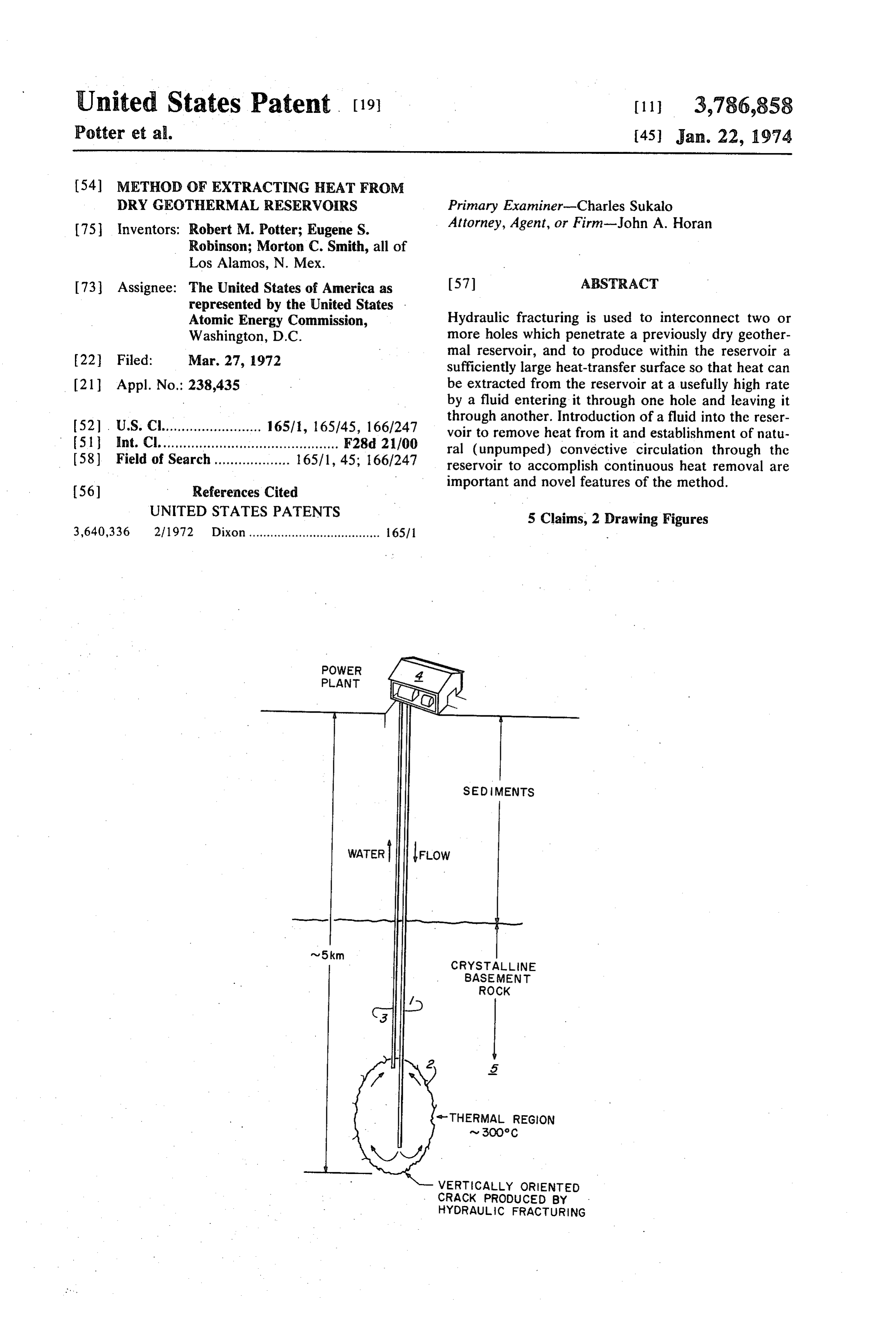
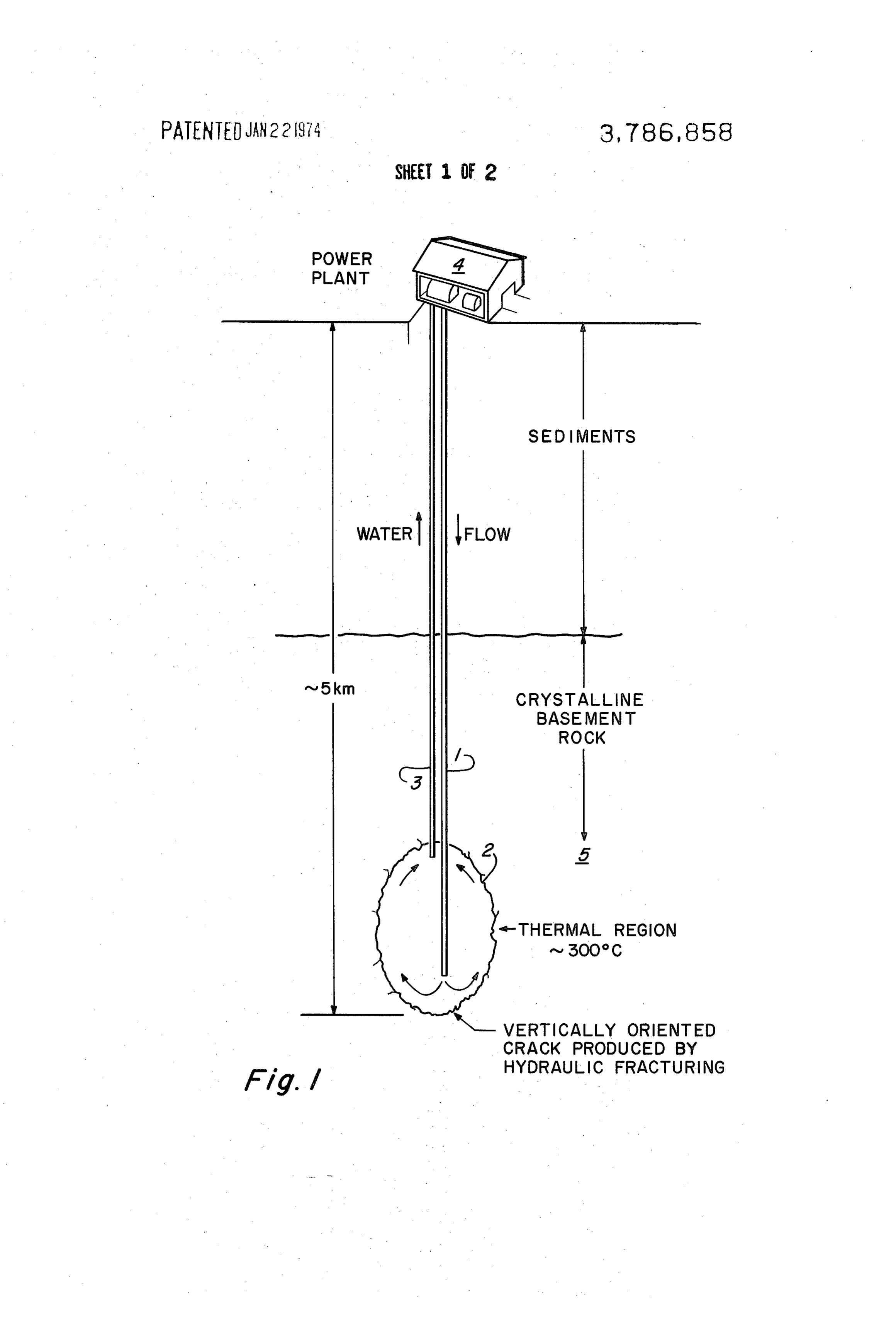
SED MENTS
CRYSTALLINE
BASEMENT
ROCK
--THERMAL REGION
VERT CALLY ORIENTED
CRACK PRODUCED BY .
HYDRAULC FRACTURING
Page 2
Drawing sheet — no readable text.
Page 3
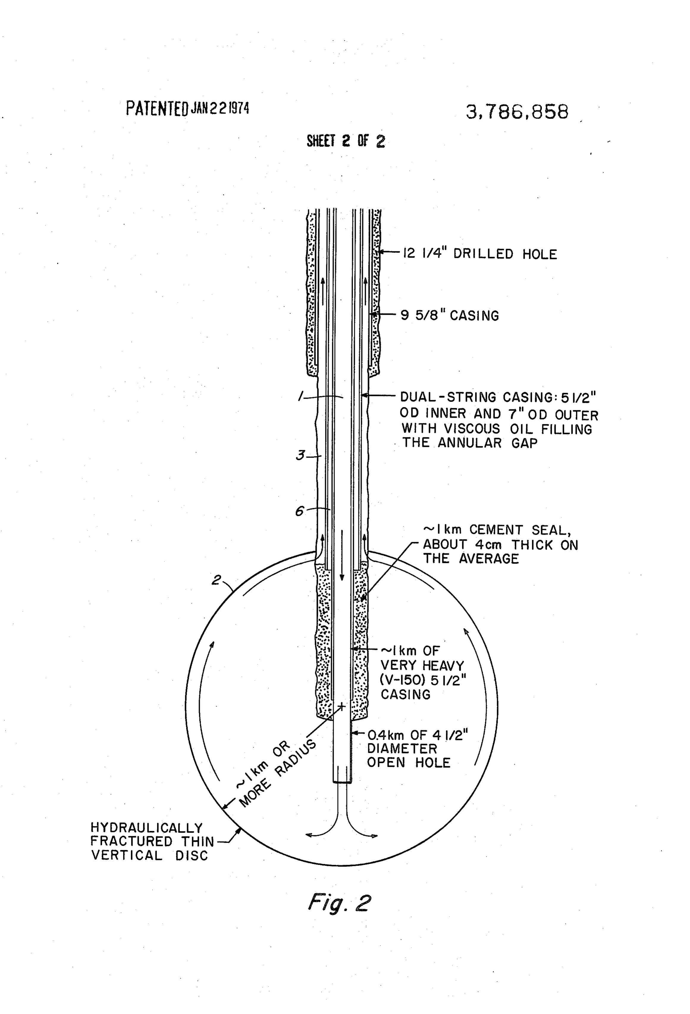
12 1/4" DRILLED HOLE
DUAL-STRING CASING: 5/2"
OD INNER AND 7" OD OUTER
WITH VSCOUS O FILLING
. THE ANNULAR GAP
^ I km CEMENT SEAL, ABOUT 4cm. THICK ON
THE AVERAGE
VERY HEAVY
CASING
DIAMETER
OPEN HOLE
HYDRAULCALLY
FRACTURED THN
VERTICAL DSC
Afg. 2
Page 4
METHOD OF EXTRACTING HEAT FROM DRY when the fracturing pressure is released. This tech GEOTHERMAL RESERVOIRS nique of creating an extended crack system in deeply The invention disclosed herein was made in the buried rock has been used extensively in a wide variety course of, or under, a contract with the U. S. Atomic of sedimentary formations whose strength properties Energy Commission. It relates to a method of extract approach those of common crystalline rocks. For ex ing energy from a dry geothermal reservoir. ample, Halliburton, 1971, cites hydraulic fracturing at BACKGROUND OF THE INVENTION 12,000 to 15,000 ft depth in the Ellenburger formation of West Texas, which is a strong, massive limestone
Many regions are known in which volcanic or intru having properties very similar to those of a granite. Be sive activity has occurred recently enough so that the 10 cause rocks are relatively weak in tension and because geothermal gradient is still as high as 150' to 190°C/km the horizontal component of lithostatic pressure is gen (435 to 550 F/mile). In such regions, temperatures erally much less than the vertical component, the fluid high enough to produce commercially useful steam pressure required to produce fracturing is much less exist within2 to 3 km (6,600 to 9,800 ft) of the earth's than might initially be supposed. surface. In a few of these places (including northern It 15 Another method of extracting geothermal energy is aly, New Zealand, northwestern Mexico, and both suggested in “A Proposal for a Nuclear Power Pro northern and southern California) a fortunate combi gram," by George C. Kennedy, USAEC Third Plow nation of geological events has caused the hot rock to share Symposium, University of California at Davis be naturally permeable or sufficiently fragmented so (1964). This report discloses a nuclear device which that it is accessible to circulating ground water, and to 20 would be detonated at the bottom of a hole creating a be overlain by impermeable rock strata which have large, rubble-filled chimney of rock and a region sur prevented its rapid cooling by the free escape of steam rounding said chimney of fractured rock. In this report or hot water. Where the overlying strata are penetrated the water is allowed to boil in the reservoir resulting in locally by natural fissures or by drilled holes, natural a marked decrease in fluid viscosity and therefore it is steam is avilable for the economical generation of 25 limited to the heat content of the initial rubble-filled power or for other uses. cavity. Also a pressurized water cycle was considered. Where natural steam is not produced, the exploita This approach was abandoned because of potentially tion of these geothermal reservoirs has not so far been large amounts of radioactive fission products that undertaken, in spite of the fact that many of them are would be brought to the surface by the circulating hot closer to the earth's surface than are the lower levels of 30 water and subsequently precipitated out on the tube a deep mine. In part this is because of the difficulty of wall surfaces of the power plant boiler. drilling or tunneling into the hot, hard, crystalline rocks SUMMARY OF THE INVENTION that compose most geothermal reservoirs. Principally, however, it is because the thermal conductivities of This invention states a means of extracting very large rocks are typically very low. Their specific heats are 35 amounts of thermal energy from the many regions of high, so that a relatively large amount of heat is avail the earth's surface known to contain abnormally hot-- able from a unit volume of the hot rock. This heat, but essentially dry-rock at depths presently attainable however, can be extracted from the rock only through using conventional drilling methods (to depths of the some free surface, such as the wall of a borehole. Since 40 order of 20,000 ft or so). Dry is defined in this applica heat is conducted to that surface quite slowly, a very tion as not containing sufficient amounts of naturally large surface is required if thermal energy is to be re occurring steam or hot water to make these regions ec moved from the rock at a usefully high rate. It has gen onomically attractive as conventional (wet) geother erally been assumed that the creation of the required mal energy sources.
amount of heat-transfer surface within a dense, crystal 45 After drilling into sufficiently hot rock, varying from line rock is not practical by existing methods. In fact, about 150 to 500°C, depending on both the econom the common oil-field technique of hydraulic fracturing ics of and proposed use for the heat, and the costs of appears to represent a simple and practical method of drilling, a very large heat transfer surface is created by developing the necessary new surface. hydraulically fracturing the surrounding rock at or near Hydraulic fracturing is a technique commonly used 50 the bottom of the hole. The fracture system thus in the petroleum and natural gas industries to create a formed will normally be in the form of a very large but system of cracks in the rock adjacent to a borehole. thin vertical circular disc (actually an oblate spheroid), These cracks facilitate the flow of crude petroleum or with a radius of the order of thousands of feet. How natural gas from the surrounding formations into the ever, the fracture system may also be in the form of well. Hydraulic fracturing is normally done by inserting 55 multiple vertical circular cracks radiating out from the temporary seals in the well above and below the zone well bore.
to be fractured, perforating the casing somewhere be . The upper portion of the fracture system will then be tween these seals, and using a high-pressure pump to connected to the surface with a shallower drilled hole produce hydrostatic pressure in this zone of the order (or by a concentric, insulated, counter-current flow of a few hundreds to a few thousands of psi above the 60 passage in the initial drilled hole). A circulating water horizontal component of the overburden pressure. A loop will then be established: down the deeper hole, crack system is created which may extend for many through the fracture system, up the shallower hole to feet from the hole, the resulting increase in volume the surface, and through the primary heat exchanger of being accommodated locally by natural porosity and by a suitable power plant. - elastic compression of the uncracked rock. Carefully 65 GENERAL DESCRIPTION OF THE DRAWINGS sized sand is usually injected with the fracturing fluid to prop the cracks open with a strong but permeable FIG. 1 is a schematic view of one embodiment of this supporting material, so that they will not spring shut invention.
Page 5
FIG. 2 is another schematic view of this invention Hydraulically Fractured Crack: showing a second embodiment employing concentric Radius ~ 1.6 km (5,250 ft) pipes to circulate a fluid through a geothermal reser Volume - 82,000 m (21.6 x 10 gal) voir. Surface Area ~ 16 km (0.17 x 109 ft)
DESCRIPTION OF THE PREFERRED
5 Depth to Center of Reservoir: ~ 5 km (16,400 ft)
EMBODIMENTS
Rock Temperature at Center of Reservoir: 300° C
The geothermal system of this invention is shown Geothermal Gradient (Assumed):
schematically in FIG. 1. The upper parts of both holes, For cryatalline basement rock: - 45°C/km through the sedimentary and/or volcanic sections are 10 For overlying sedimentary rock: ~ 75°C/km drilled 17% inches in diameter and lined with 13% inch (~ 2 km at K = 0.0036 cal/cm-sec- C) steel casing, cemented in place. The first (deeper) hole CASED AND DRILLED HOLE SIZES AND DEPTHS is extended at a 12 inch diameter to a depth of about 14,800 ft or until a rock temperature of about 300°C is encountered. This section is cased with 9% inch cas 15 (Conventional oil field casing and drill bit sizes are as ing 1. The hole is continued for an additional 200 ft or sumed) so with an 8% inch bit, and this last section of hole is Injection (deeper) Hole:
left uncased. At a point about 1,200 ft above the bot Depth ~ 5 km (16,400 ft) tom of the hole, the casing is jet perforated. A string of Upper Half: 17% inches drilled hole, 13% inches cas 7-inch high-pressure tubing would be run down the 20 ing hole, which would be packed-off above the perforated Lower Half: 12% inches drilled hole, 9% inches cas zone. The crystalline rock is fractured hydraulically, ing and the resulting crack 2 extends out to a radius of Withdrawal (shallower) Hole:
about 1,500 to 4,000 ft. The second drill hole 3, at a Depth ~ 3.5 km (11,500 ft) location chosen to encounter the upper part of the ini 25 Upper Two-thirds: 17% inches drilled hole, 13% tial hydraulically fractured crack system, is drilled inches casing through the crystalline rock 5 at a 12-inch diameter Lower One-third: 12% inches open hole until the desired intersection occurs. If circulation to the first hole has not then been established, directional RESERVOIR THERMAL/FLOW POTENTIAL drilling would be used from this point to probe for the 30 Reservoir Lifetime: ~ 10 years crack system 2. The cold water pipe inflow system 1 is (Excluding any contribution due to thermal stress connected through the vertical hydraulically fractured cracking) crystalline basement rock 5 to the return hot water pipe Average Pressurized Water Flow Rate: 265 kg/sec' system 3 which in turn is connected to a heat ex 35 (This is ~ 6 x 10 gal/day at the earth inlet) changer, turbine means, and a conventional power Earth Inlet Conditions:
plant 4 at the surface. T = 65° C (149°F)
Alternatively, or as a supplement to directional dril P = 70 kg/cm (1,000 psia) ling, hydraulic fracturing could be repeated from the Earth Outlet Conditions (Average): bottom of the second hole. A still further solution to T = 280° C (536°F) this problem is shown in FIG. 2. The cold water is 40 P = 80 kg/cm (1,140 psia) pumped down an inner pipe insulated by any well Average Thermal Power: 250 MW known means from the return heated water flowing up Potential Electrical Power Generation ~ 50 MW) the outer pipe. Thus by placing a string of pipe within (at a net efficiency of 20 percent) a larger pipe communication with the reservoir would 45 "Natural convection only (no pumping) - conditions averaged over be assured. In particular the inner pipe 1 having a vis 10 year lifetime.
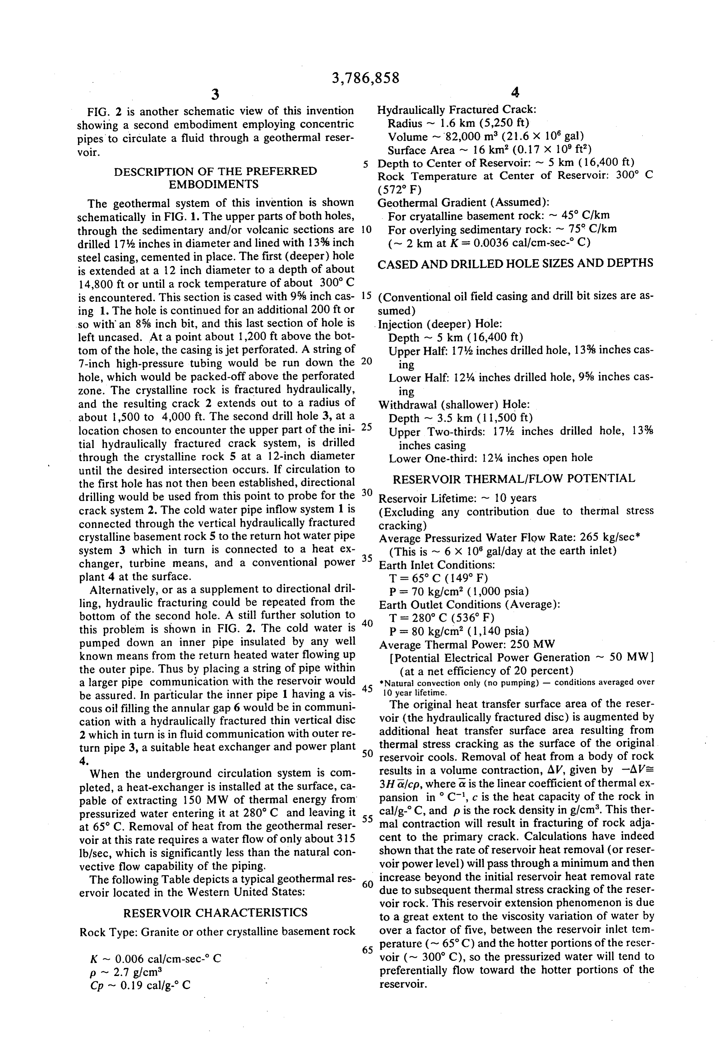
cous oil filling the annular gap 6 would be in communi The original heat transfer surface area of the reser cation with a hydraulically fractured thin vertical disc voir (the hydraulically fractured disc) is augmented by 2 which in turn is in fluid communication with outer re additional heat transfer surface area resulting from turn pipe 3, a suitable heat exchanger and power plant 50 thermal stress cracking as the surface of the original 4. reservoir cools. Removal of heat from a body of rock When the underground circulation system is com results in a volume contraction, AV, given by -AVs pleted, a heat-exchanger is installed at the surface, ca 3Ha/cp, where a is the linear coefficient of thermal ex pable of extracting 150 MW of thermal energy from pansion in C, c is the heat capacity of the rock in pressurized water entering it at 280° C and leaving it 55 cal/g-C, and p is the rock density in g/cm. This ther at 65° C. Removal of heat from the geothermal reser mal contraction will result in fracturing of rock adja voir at this rate requires a water flow of only about 315 cent to the primary crack. Calculations have indeed lb/sec, which is significantly less than the natural con shown that the rate of reservoir heat removal (or reser vective flow capability of the piping. voir power level) will pass through a minimum and then The following Table depicts a typical geothermal res 60 increase beyond the initial reservoir heat removal rate ervoir located in the Western United States: due to subsequent thermal stress cracking of the reser voir rock. This reservoir extension phenomenon is due
RESERVOIR CHARACTERISTICS to a great extent to the viscosity variation of water by Rock Type: Granite or other crystalline basement rock over a factor of five, between the reservoir inlet tem 65 perature (~ 65° C) and the hotter portions of the reser
K - 0.006 cal/cm-sec- C voir (~ 300° C), so the pressurized water will tend to p ~ 2.7 g/cm preferentially flow toward the hotter portions of the Cp ~ 0.19 cal/g- C reservoir.
Page 6
S 6
For a reservoir depth of 15,000 ft, there is a pressure What we claim is:
difference of about 1,500 psi between the descending 1. A method of extracting energy from a dry igneous cold water column and the ascending hot water col rock geothermal reservoir comprising: umn. This pressure difference arises from the 21 per a. drilling a hole to such a depth as is required to en cent density difference between the cold and hot water 5 counter hot igneous rock in the range of 150 to columns. Thus, this AP is available to overcome fluid 500°C;
friction losses in the piping and heat exchanger, elimi b. hydraulically fracturing from this hole to produce nating the need for a circulating pump in the pressur a large crack system in the rock; ized water loop. c. pumping cold fluid down the hole to establish un The essential novel features of the method disclosed O derground circulation through the crack system; herein are directed to the fact that thermal stress crack d. extracting thermal energy from the pressurized hot ing of the reservoir rock as heat is removed by the con fluid rising in a shallower flow passage and then to vective flow of pressurized water would produce a con tinually enlarging crack system so as to significantly ex- . e. are-introducing heat-exchanger at the surface; and the cooled fluid from the heat tend the useful life of the geothermal source. In fact, exchanger into the crack system. the heat quality (temperature level and available ther 2. The method of claim in which the said cold fluid mal energy) of the geothermal source should improve as energy is drawn from it. A second point is that hy causes a second crack system to develop which is in communication with the initial crack system.
draulic fracturing, although old in the oil field art, has never been used to fracture dry igneous or hot rock or 2 3. The method of claim 1 in which the said hole con for the express purpose of creating heat transfer sur tains both the cold and hot fluid flow passages. face area. The operating temperatures of the geother 4. The method of claim 1 in which the temperature mal reservoir must be at least 150 C, and although of said hot rock is about 300 C.
there is no critical maximum temperature, one would 5. The method of claim 1 in which the said fluid is not seek temperatures in excess of 500 C because of 25 water. k xk k k prohibitive drilling costs.
Provenance
- Collection
- Cited prior art
- Original PDF
- patentimages.storage.googleapis.com →
- Filed
- 1972-03-27
- Pages
- 6
- Method
- pdftotext (the PDF's own text layer) + pdftoppm 300dpi page scans
- Source
- Google Patents bibliographic record
- Granted
- 1974-01-22
- Inventors
- R Potter; E Robinson; M Smith; US Atomic Energy Commission (AEC)
- Transcribed from
- patentimages.storage.googleapis.com →