patent · US4371500
Apparatus for generating hydrogen
1 February 1983
Page 1 — bibliographic record
United States Patent (19) 11) 4,371,500 Papineau
(54) APPARATUS FOR GENERATING 3,442,620 5/1969 Huebier ............................... 423/658 HYDROGEN 3,450,506 6/1969 Guerieri .............................. 422/197 75) Inventor: Ronald I. Papineau, Goshen, Mass. 3,798,005 3/1974 Koch ............................... 422/203 X
73) Assignee: Unique Energy Systems, Inc., 3,967,589 7/1976 Papineau ......................... 422/198 X Holyoke, Mass. FOREIGN PATENT DOCUMENTS (21) Appl. No.: 175,597 2549370 6/1976 Fed. Rep. of Germany ... 423/657 (22 Filed: Aug. 5, 1980 OTHER PUBLICATIONS Related U.S. Application Data Gregory, "A Hydrogen-Energy System", American
63 Continuation of Ser. No. 921,000, Jun. 30, 1979, aban doned. Primary Examiner-Barry S. Richman 51) Int. Cl. ........................... B01J 8/06; CO1B 3/08;
Attorney, Agent, or Firm-Morgan, Finnegan, Pine,
Foley & Lee
52 U.S. C. .................................... 422/115; 422/197; (57) ABSTRACT 422/198; 422/203; 422/223; 423/648 R; A hydrogen generating system which produces hydro 423/657; 423/658 gen instantaneously from water ready for use upon 58) Field of Search ................. 422/197, 198, 203, 62, demand. The system includes a reactor that has reaction 422/114, 115, 223; 423/648 R, 657, 658 zones wherein catalyst and elevated temperatures gen 56) References Cited erate hydrogen from steam. The zones in the reactor
chamber, and the zones are adapted to be intercon 1,129,559 2/1915 Dicke .............................. 422/197 X nected to each other, to atmosphere, and to the source 1,617,965 2/1927 Bochet ................................ 423/658 of steam, all to maximize the generation of hydrogen by 1,871,004 8/1932 Lopez ... ...... 252/477 R. providing a reactor of optimum flexibility. 2,263,363 11/1941 Menshih .......................... 422/223 X 2,393,839 1/1946 Thomas et al. ... ...... 422/223 X The present invention also is directed to systems which 2,635,948 4/1953 Hasche .............. ...... 422/223 X include the hydrogen generating system and which 2,817,691 12/1957 Hutchins ......................... 422/223 X utilize the generated hydrogen as a fuel or as a chemi 3,129,065 4/1964 Korwin ............................... 422/197 cal, 3,278,268 10/1966 Pfefferle........ ...... 422A98 X 3,350,176 10/1967 Green et al. .................... 422/198 X 18 Claims, 27 Drawing Figures
Page 2
Drawing sheet — no readable text.
Page 3
Drawing sheet — no readable text.
Page 4
Drawing sheet — no readable text.
Page 5
Drawing sheet — no readable text.
Page 6
Drawing sheet — no readable text.
Page 7
Drawing sheet — no readable text.
Page 8
Drawing sheet — no readable text.
Page 9
Drawing sheet — no readable text.
Page 10
Drawing sheet — no readable text.
Page 11
Drawing sheet — no readable text.
Page 12
Drawing sheet — no readable text.
Page 13
Drawing sheet — no readable text.
Page 14
Drawing sheet — no readable text.
Page 15
Drawing sheet — no readable text.
Page 16
Drawing sheet — no readable text.
Page 17
Drawing sheet — no readable text.
Page 18
Drawing sheet — no readable text.
Page 19
Drawing sheet — no readable text.
Page 20
Drawing sheet — no readable text.
Page 21
produces hydrogen from water adapted for instanta
APPARATUS FOR GENERATING HYDROGEN neous use at the option of the consumer. It is a primary object of the invention, therefore, to
This is a continuation, of application Ser. No. 921,000 provide a new and improved method of and apparatus filed June 30, 1978 now abandoned. 5 for producing hydrogen for chemical and energy pur poses.
FIELD OF INVENTION It is another primary object of the invention to pro This invention relates to a method of and apparatus vide a new generating system which economically pro for instantaneously generating hydrogen from water duces hydrogen from water adapted to be used upon upon demand, where needed as needed. This invention 10 demand where needed, as needed, and which is an im also relates to systems which include the described provement of the system of my earlier patent, U.S. Pat. method and apparatus and which utilizes the generated No.It 3,967,589.
is another object of the invention to provide a new hydrogen.
system which produces hydrogen from water without
BACKGROUND OF THE INVENTION 15 substantially depleting the supply of water or polluting There is a continuing critical need to more efficiently theItenvironment.
is still another object of the invention to provide a produce hydrogen in substantial quantities for forming new system which produces hydrogen ready for instan chemical products and in chemical processes. taneous use without the need for an intermediate stor Presently, large quantities of hydrogen are consumed 20 age facility.
in the manufacture of ammonia and methanol, and in
Another producing other alcohols, nitrates and amines. Hydro energy system object of the invention is to provide a new gen also is used in the hydrogenation of organic com which produces low-cost hydrogen. Among pounds, such as oils and fats to make margarine and vide hydrogen generating the other objects of the invention is to pro vegetable shortening. and utilizing systems for di 25 rect applications which serve human needs, such as
In the steel making industry hydrogen is being used in increasing quantities in the direct reduction of iron ores commercial, for land, marine industrial and home heating, propulsion and aerospace vehicles, and the genera to produce metallic iron which may be fed to steel making furnaces, open hearth furnaces, electric fur tion of electricity by utilities, by commercial and indus trial enterprises, as well as by the homeowner.
naces and as part of the feed for blast furnaces. 30 It is still a further object of this invention to provide Further, hydrogen can be used for such diverse uses a new and improved hydrogen generating system for as the gasification and liquification of coal, the reduc wherever hydrogen is used chemically in forming hy tion of oxides of tungsten and molybdenum to the met drogen containing products as well as for processes als, the providing of high protein foods through biosyn where hydrogen can be used advantageously. thesis of hydrogen and carbon dioxide, and in total 35 Additional objects and advantages will be set forth in water management programs to pasturize pathogens, part hereinafter and in part will be obvious herefrom or Apart from the growing need as a chemical, hydro may be learned with the practice of the invention, the gen, for some time, has been considered as a possible same being realized and obtained by means of the sys alternative to fossil fuels: oil, natural gas and coal. Hy tems and applications, recited in the appended claims. drogen is an excellent fuel available in abundance. SUMMARY OF THE INVENTION Water provides an undepletable supply of hydrogen.
When it burns, hydrogen produces extraordinary quan In accordance with the present invention, there is tities of heat and essentially pollution free water vapor provided a hydrogen generating system including a useful once again as a source of more hydrogen. plurality of reaction zones which contain catalyst and Prior to the present invention, however, hydrogen 45 which are maintained at elevated temperatures. Steam has not been produced upon demand in an economic (or water) is adapted to be conveyed to each catalyst ane. containing zone, wherein hydrogen is generated from Available systems, generally, do not provide hydro the steam (or water), and wherein the generated hydro gen for instantaneous use. Presently, existing systems gen is conveyed from the zone ready for use upon de commonly require production and storage, or substan 50 mand, where needed, as needed. The invention includes tial accumulation, before utilization. There is no direct forming adjacent reaction zones in a reactor containing link between production and use. Storage, a necessary a catalyst in each zone, and maintaining the zone at element in such existing systems, prohibits' instanta elevated temperatures, to produce hydrogen from neous use of hydrogen upon production. steam fed thereinto. The zones in the reactor can be in This is not meant to say that storage is necessarily 55 the form of longitudinal bores or tubes which extend detrimental. Generally, however, the consumer has not along the length of the reactor about a heat generating had the option of either directly using the hydrogen or chamber. At least one end of the reactor includes trans storing the hydrogen and using it when needed. Pres verse and radial passages, adapted to interconnect the ently storage is required. longitudinal zones with each other, with the surround In addition, available systems do not produce hydro ing atmosphere and with the source for steam, all to gen economically. The price for hydrogen is not com maximize the generation of hydrogen by providing a petitive with available sources of energy. Also, it often reactor of maximum flexibility.
takes more energy to produce hydrogen than the en It is believed that hydrogen is generated by the inven ergy available from the produced hydrogen. tion because of the interaction of the high temperatures In sum, there is a need to more efficiently produce 65 and the catalyst upon the steam (or water). At the high large quantities of hydrogen for chemical purposes, and temperatures, it is believed the steam (or water) be there is a pressing need to make available an economic, comes super heated steam which tends to disassociate in ecologically sound energy generating system which the presence of the catalyst, to produce hydrogen gas.
Page 22
In any event, by practice of the invention, hydrogen is drogen by further elevating the temperatures in a juxta produced from water which is instantaneously available posed hydrogen generating zone. for use either as an essentially pollution free fuel, which, To provide these concurrent reactions in adjacent when burned, again produces water, or as a chemical Zones, initially, the steam can be supplied to one zone wherever hydrogen is required in products or pro while nothing is supplied to the adjacent zone. Once the CeSSeS. catalyst is deactivated in the one zone, concurrent oper The catalyst of the system, generally, is metallic and ation can be commenced. For example, when there are contains innumerable sites on its surface, which, with eight Zones positioned circumferentially about the heat the elevated temperature in each zone, effect the gener generating chamber, initially steam can be supplied to ation of hydrogen. Illustratively, the catalyst is formed 10 every other zone (a set of four zones). Once the catalyst of a web-like cellular structure defined by intercon in such every other zone becomes deactivated, then nected metal filaments comprising iron, copper, silver, concurrent operations are commenced so that the exo nickel, palladium, platinum, or iron-nickel and molyb thermic reactivating reaction occurs in such every denum. other zone while the endothermic hydrogen reaction Where the catalyst becomes deactivated because of 5 occurs in the alternate adjacent zones (a second set of use in the present invention, it is regenerated, in situ. four zones) with the aid of the exothermic heat. For example, the innumerable reaction sites on a cata Preferably, means are provided at the other end lyst surface of iron will become oxidized by the steam to (downstream) of the reaction zones which can deter produce hydrogen gas until the sites are oxidized. In mine when the tubes are no longer producing hydrogen such instance, the catalyst sites become deactivated. To 20 because of deactivation of the catalyst. At this time the reactivate the sites a reducing agent, such as hydrogen control conduit circuit can cease providing steam to the or hydrocarbons or mixtures thereof, can be used. Once non-productive tubes and begin providing the hydrogen reactivated, steam can be fed to such catalyst to once or hydrocarbons to such tubes to reactivate them. Once again generate hydrogen. the catalyst has been regenerated the means will deter As used herein, the term "deactivation' describes the 25 mine that regenerating hydrogen is being conveyed condition of the catalyst when it is no longer substan through that tube so that the control conduit circuit can tially effective as a catalyst in the production of hydro reverse the described procedure and begin to supply gen, and the term "activated" describes the condition of steam to the reactivated catalyst. the catalyst when it is effective in the production of In the embodiment of the invention where the cata substantial quantities of hydrogen. 30 lyst is not deactivated by the steam, e.g., a catalyst In this embodiment of the invention, the generating formed from a platinum type of metal, the conduit sys system includes control means, responsive to the deacti tem can continuously supply steam to each reactor tube vation of the catalyst, adapted to halt the supply of and continuously convey the generated hydrogen steam to the zone containing such catalyst and to pro therefrom, vide a catalyst regeneration agent which, once again, 35 In each embodiment'of the invention the generating activates the catalyst. At such time the control means system can include downstream cooling means for re are adapted to reverse the process by halting the supply ducing the temperature of hydrogen and other fluids of the regenerating agent and by supplying steam to the conveyed from the reactor. In doing so meaningful reaction zone for the generation of hydrogen. reformation of the hydrogen and oxygen to form water A conduit system at each end of the reactor and con 40 is prohibited and the temperature of the fluids is re nected to the zones or tubes conveys fluid to and from duced to make them easier to handle by components of the reactor. At one end, e.g., upstream of the reactor, a the system which separate and collect fluids, as hereaf control conduit circuit selectively provides to the tubes ter described in more detail.
or zones steam from a steam generator for the produc In addition, as hereafter explained in more detail, the tion of hydrogen and a reducing agent, such as hydro 45 method and apparatus of the present invention can be gen or hydrocarbon, to the tubes for the reactivation of included in systems which utilize hydrogen to form the catalyst. At the other end, e.g., downstream, the chemical products and in chemical processes, as well as conduit system conveys fluids from the reactor, includ in systems which use hydrogen as a fuel for such diverse ing the hydrogen generated within the reactor, applications as heating, propulsion and electricity, Once the system is in full operation selected zones or 50 tubes will contain an active catalyst while adjacent AND BRIEF DESCRIPTION OF THE DRAWINGS zones or tubes will contain deactivated catalyst. Under ILLUSTRATIVE EMBODIMENT OF THE such conditions the control conduit circuit concur INVENTION rently provides steam to each tube containing active The following is a detailed description together with catalyst and a reducing agent, such as hydrogen, to each 55 accompanying drawings of preferred and illustrative tube containing deactivated catalyst. In each active embodiments of the invention. It is to be understood zone to which steam is supplied, the elevated tempera that the invention is capable of modification and varia tures and catalyst decompose the steam to produce tion apparent to those skilled in the art within the spirit hydrogen gas. This reaction is endothermic in nature and scope of the invention.
because the heat is absorbed by the reaction. Simulta In The Drawings:
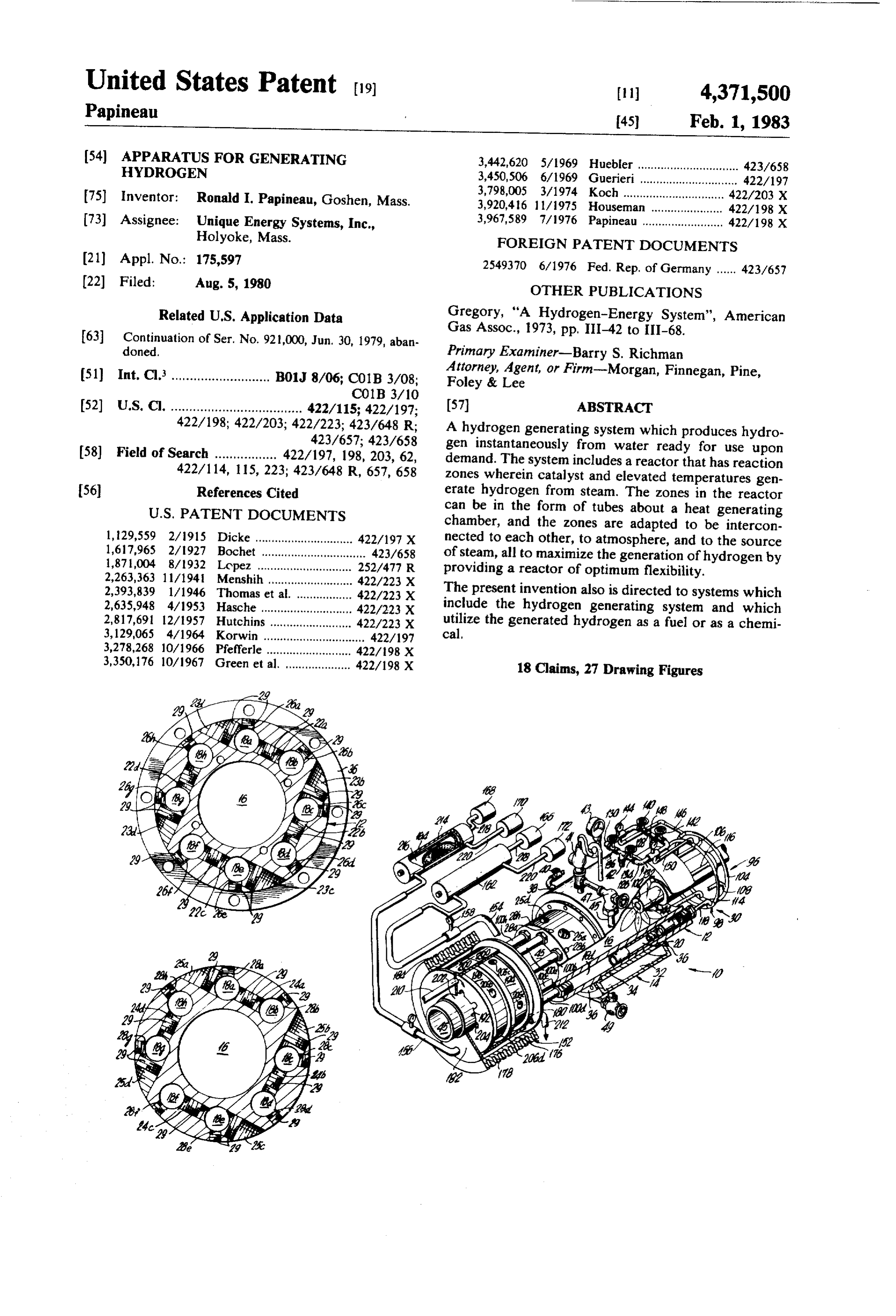
neously, in each deactivated zone to which hydrogen is FIG. 1 is a perspective view of one embodiment of supplied, the reducing agent reacts with the oxidized the invention.
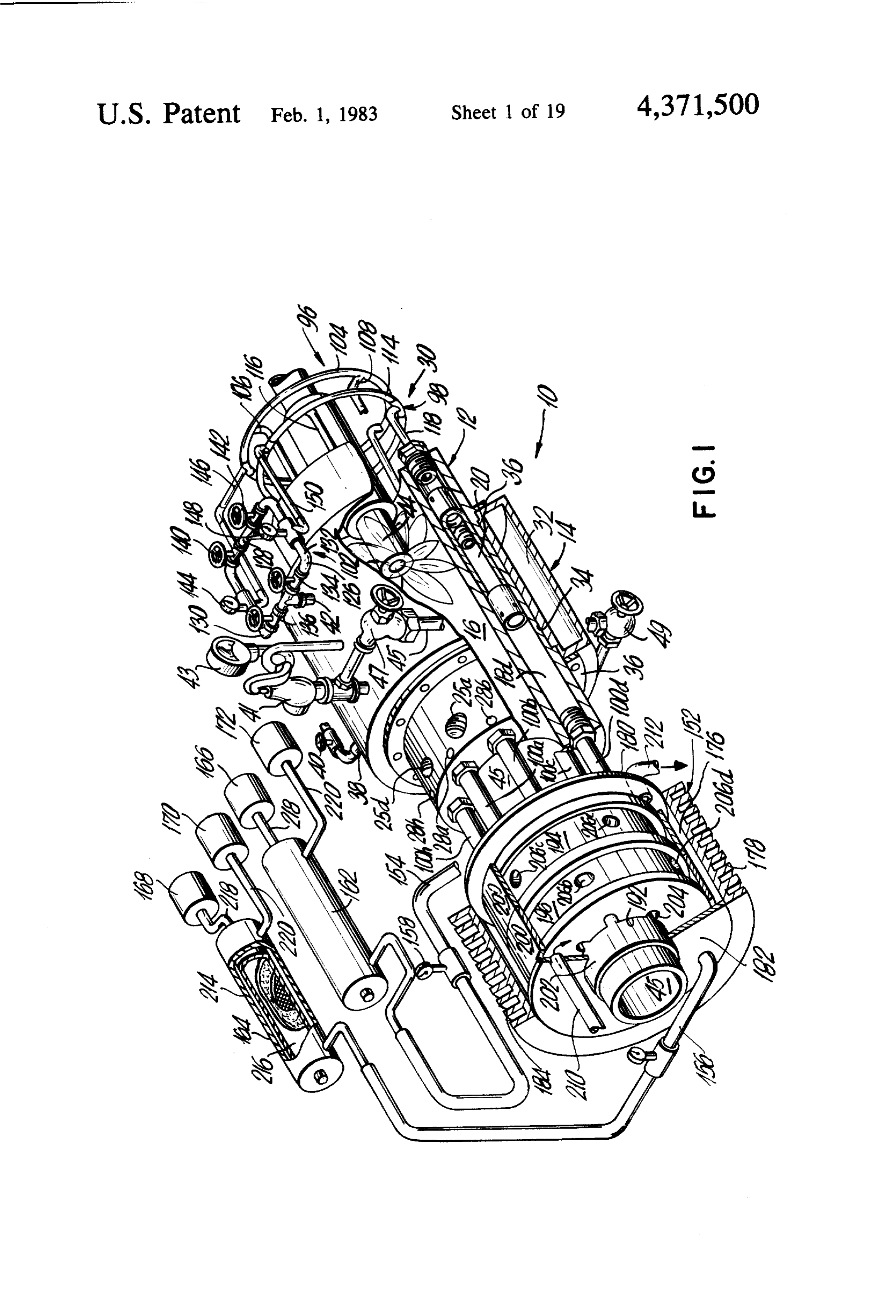
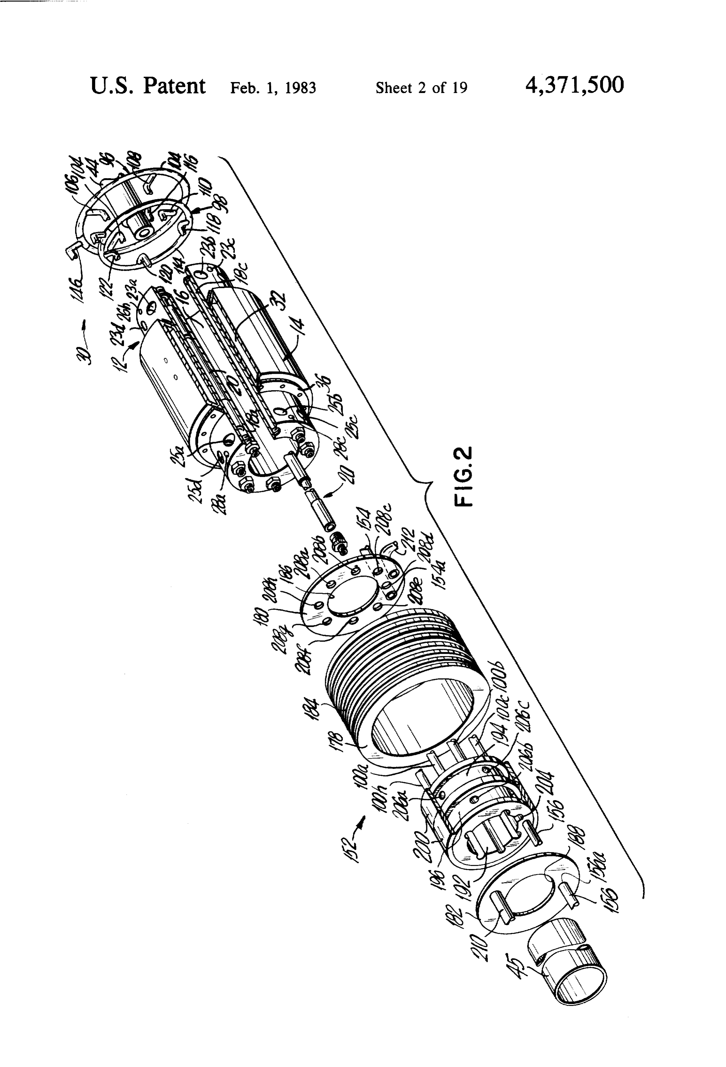
catalyst to remove the oxygen from the catalyst surface FIG. 2 is an exploded, perspective view of the em to thereby regenerate or reactivate the catalyst. This bodiment of the invention shown in FIG. 1, wherein reaction produces water and is exothermic in nature 65 structure of several components of the system have because heat is generated by the reaction. By conduct been partially broken away to show details thereof. ing the described reactions in adjacent zones, the exo FIG. 3 is a cross-sectional view of the upstream end thermic heat is used to increase the production of hy of the reactor.
Page 23
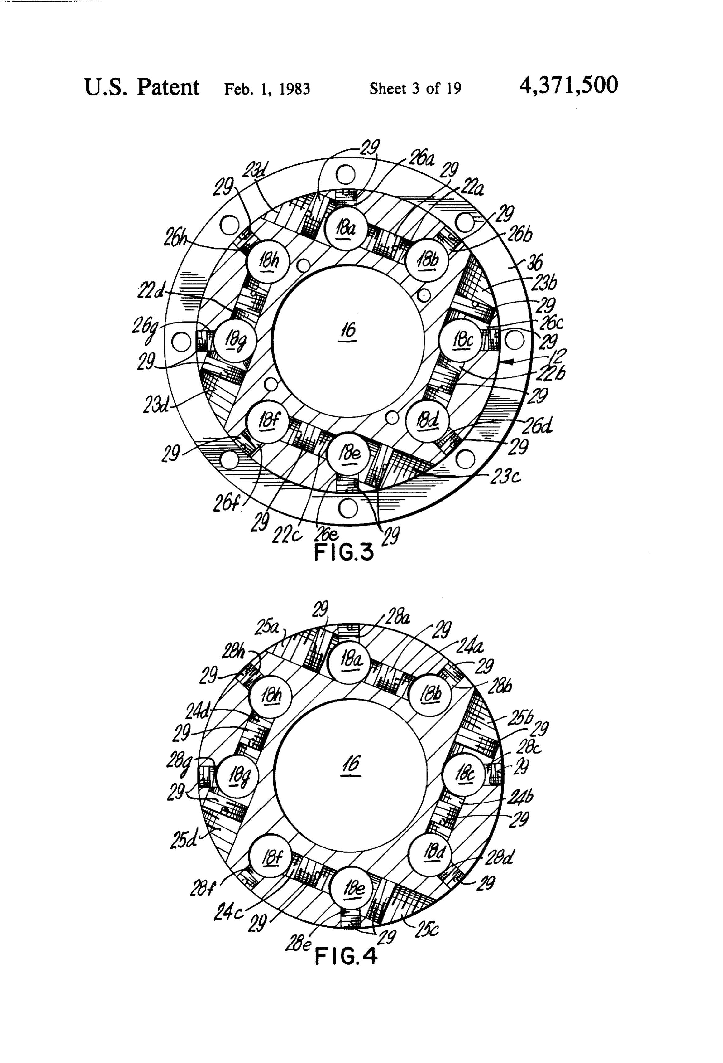
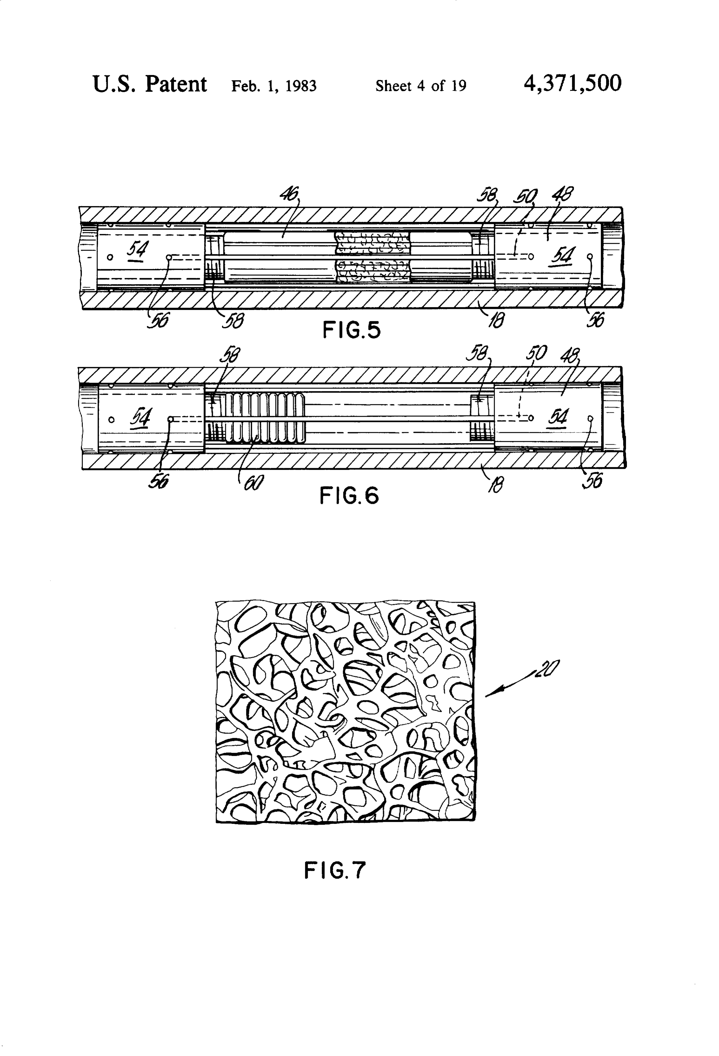
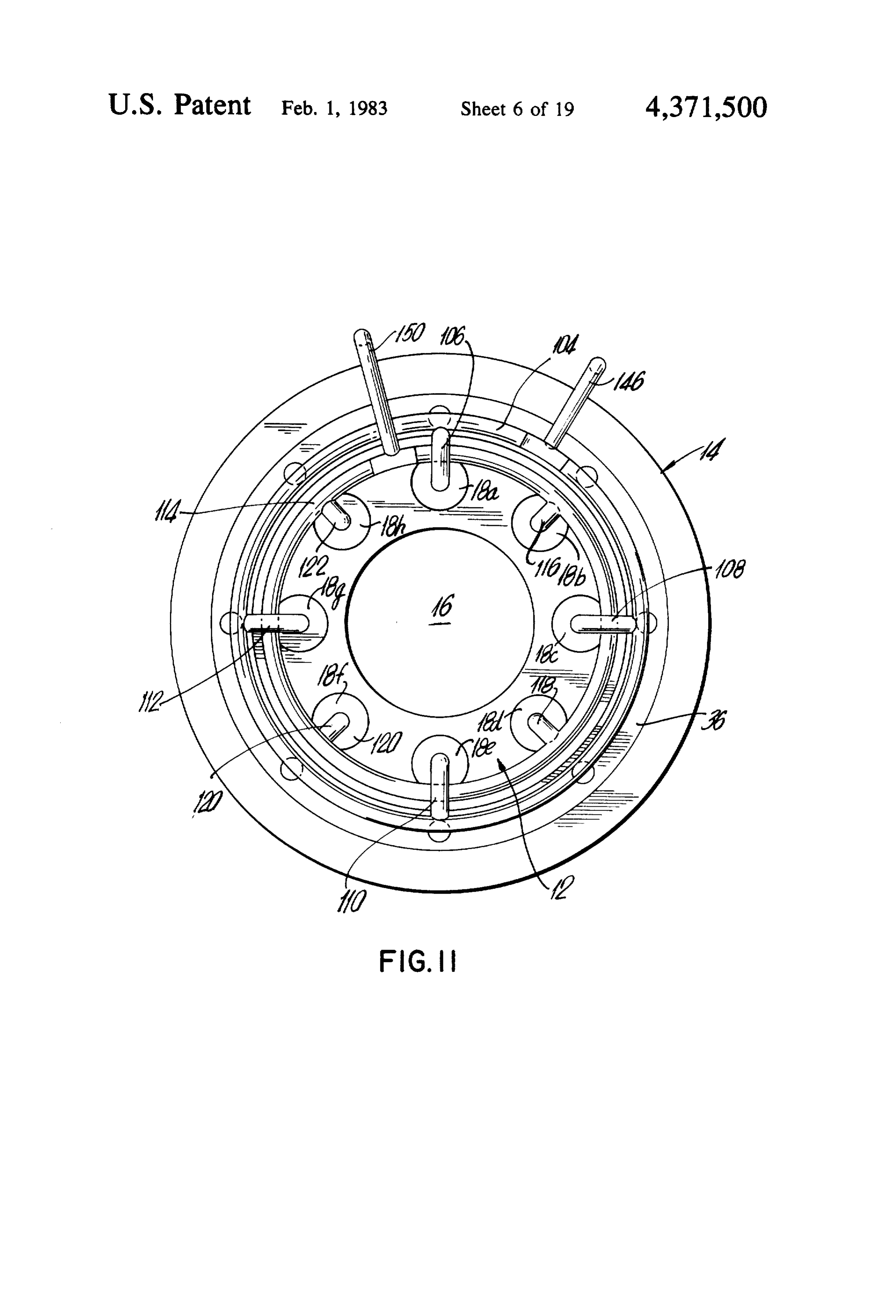
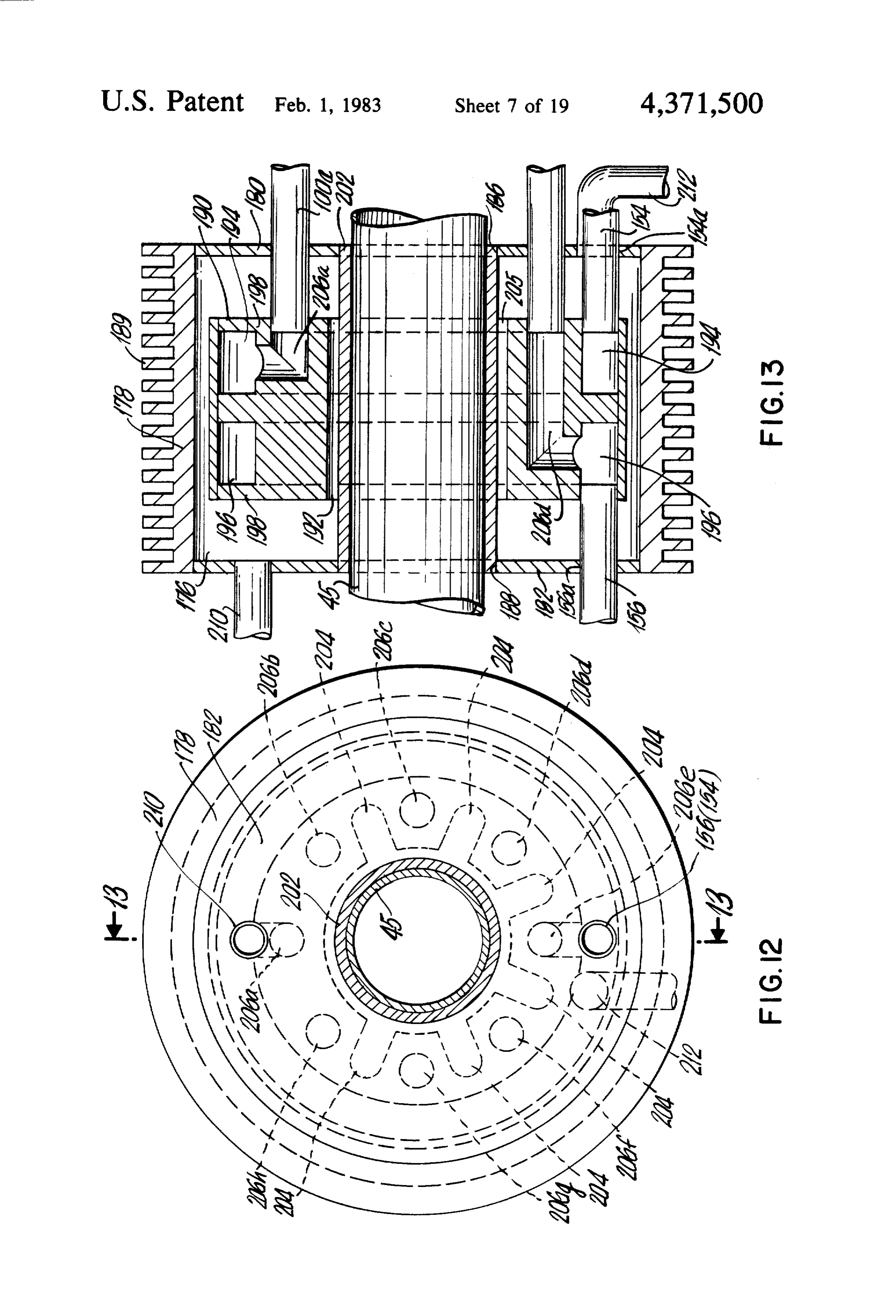
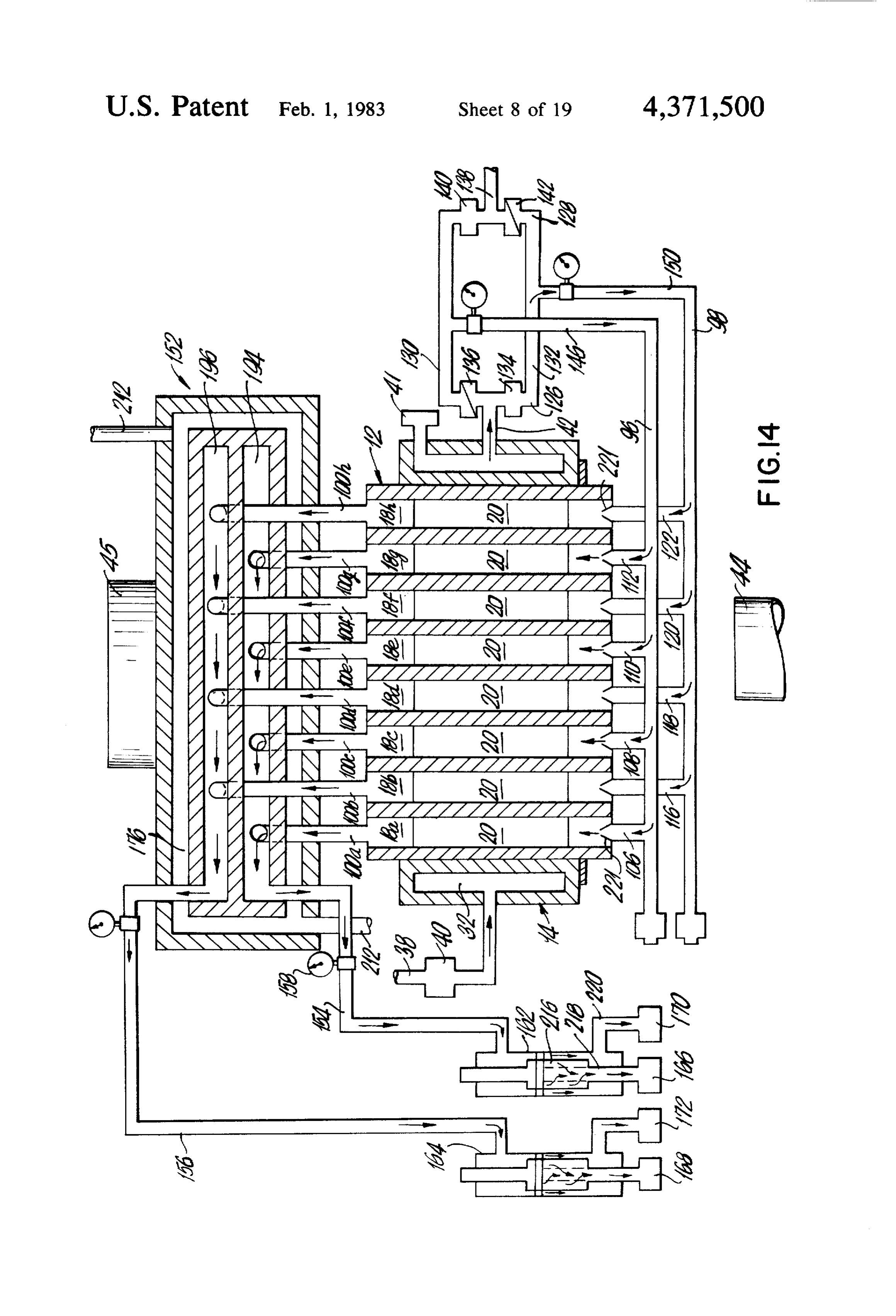
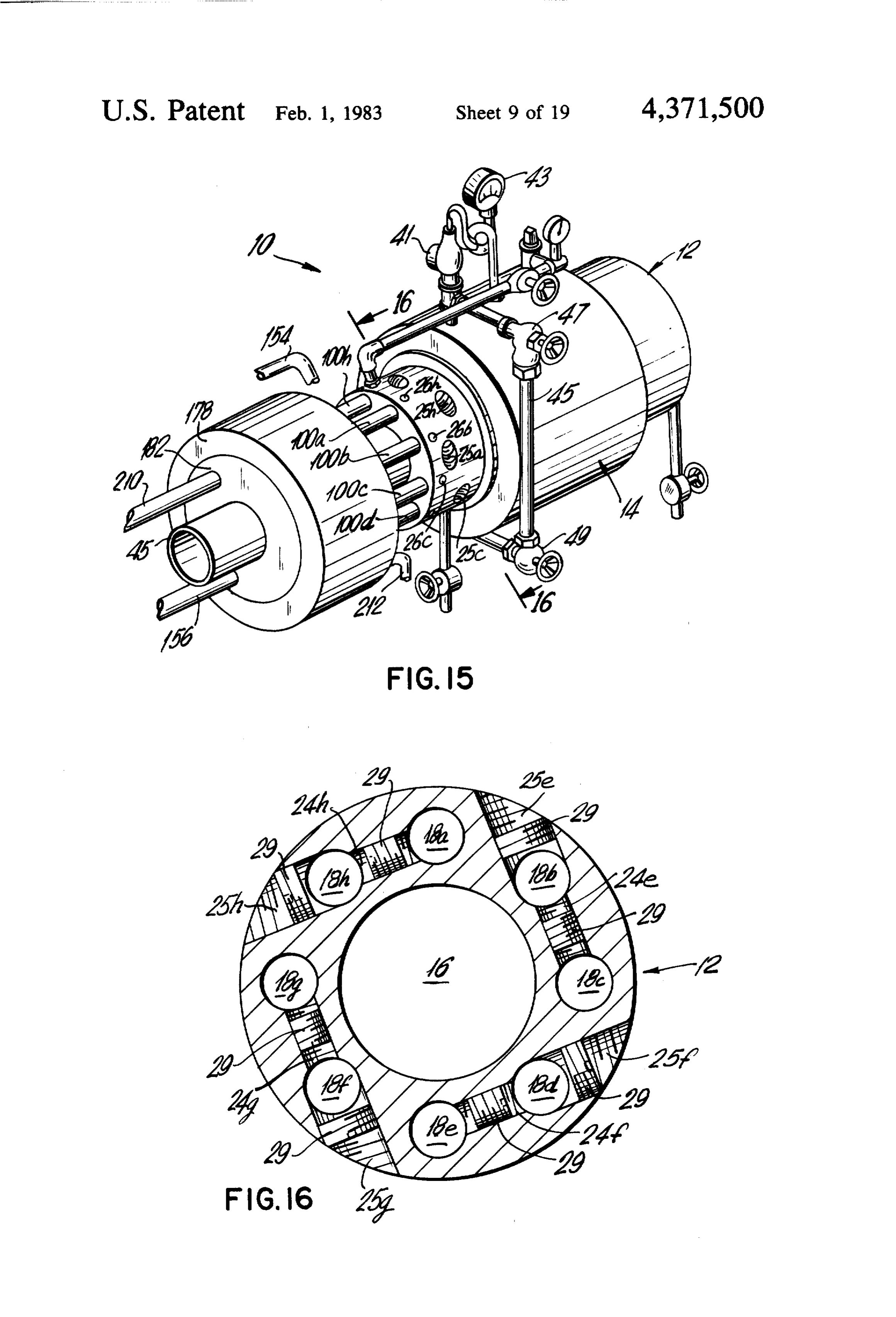
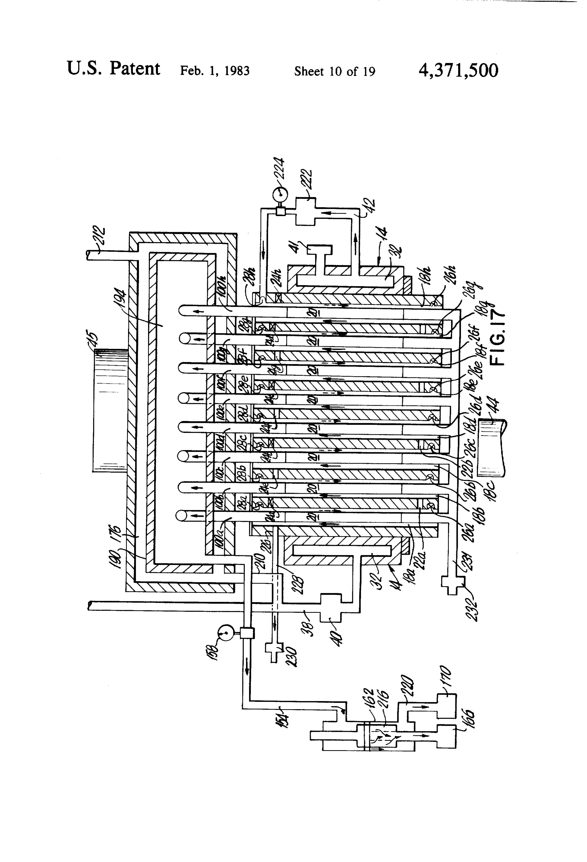
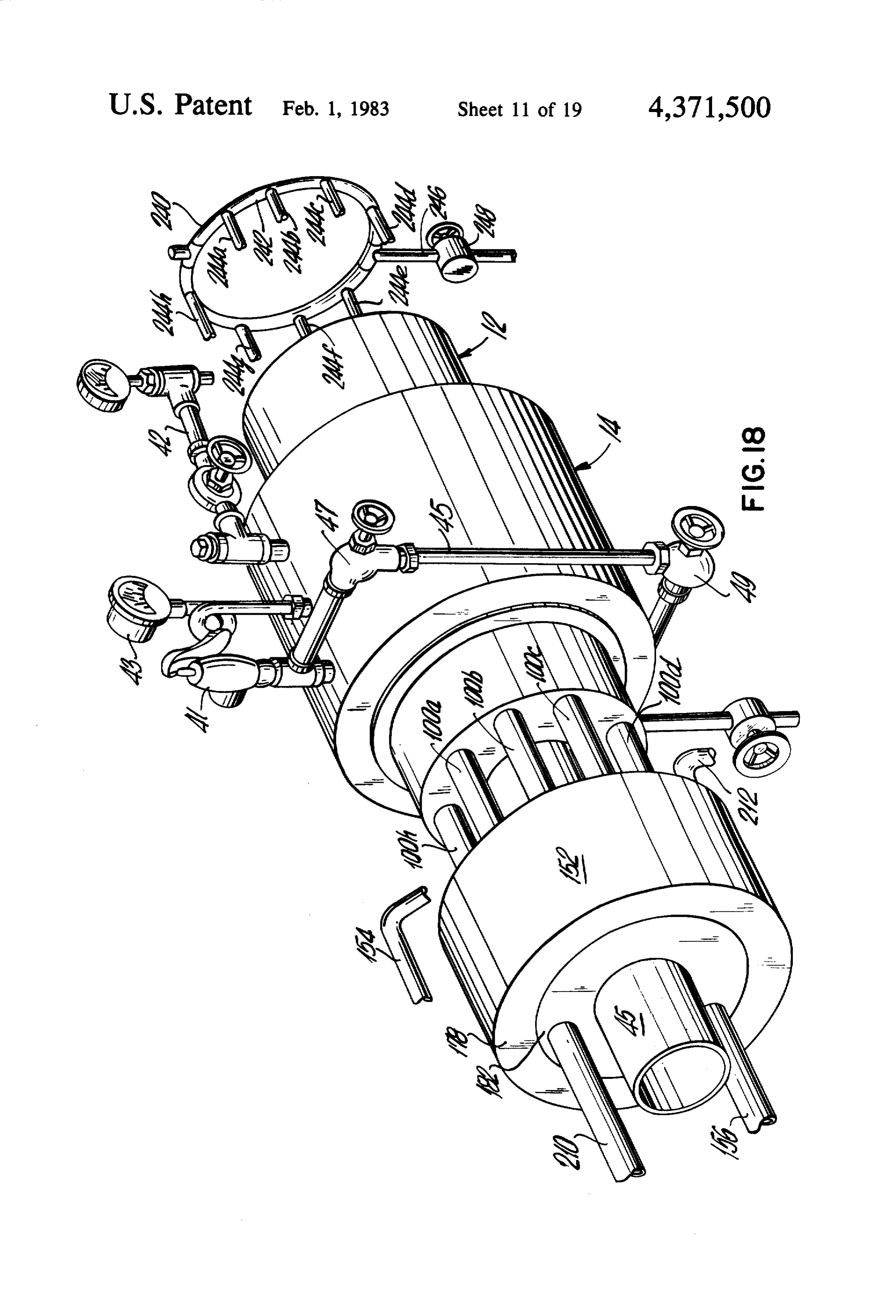
FIG. 4 is a cross-sectional view of the downstream FIG. 26 is a planar view, diagrammatically illustrat end of the reactor, taken along the lines 4-4 of FIG. 1, ing the reactor of the present invention for the Stirling FIG. 5 is a longitudinal sectional view of a tube of the cycle engine shown in FIG. 25.
reactor containing one embodiment of the catalyst sys FIG. 27 is a side view, diagrammatically illustrating tem of the invention, 5 the system of the invention for producing hydrogen fuel FIG. 6 is a longitudinal sectional view of a tube of the for a fuel cell which generates electricity. reactor containing another embodiment of the catalyst system of the invention. FIGURES 1-14 FIG. 7 is a magnified view of a portion of the catalyst of either FIGS. 5 or 6. O Referring first to FIGS. 1-2, there is shown a pre ferred embodiment of the system 10 of the invention for
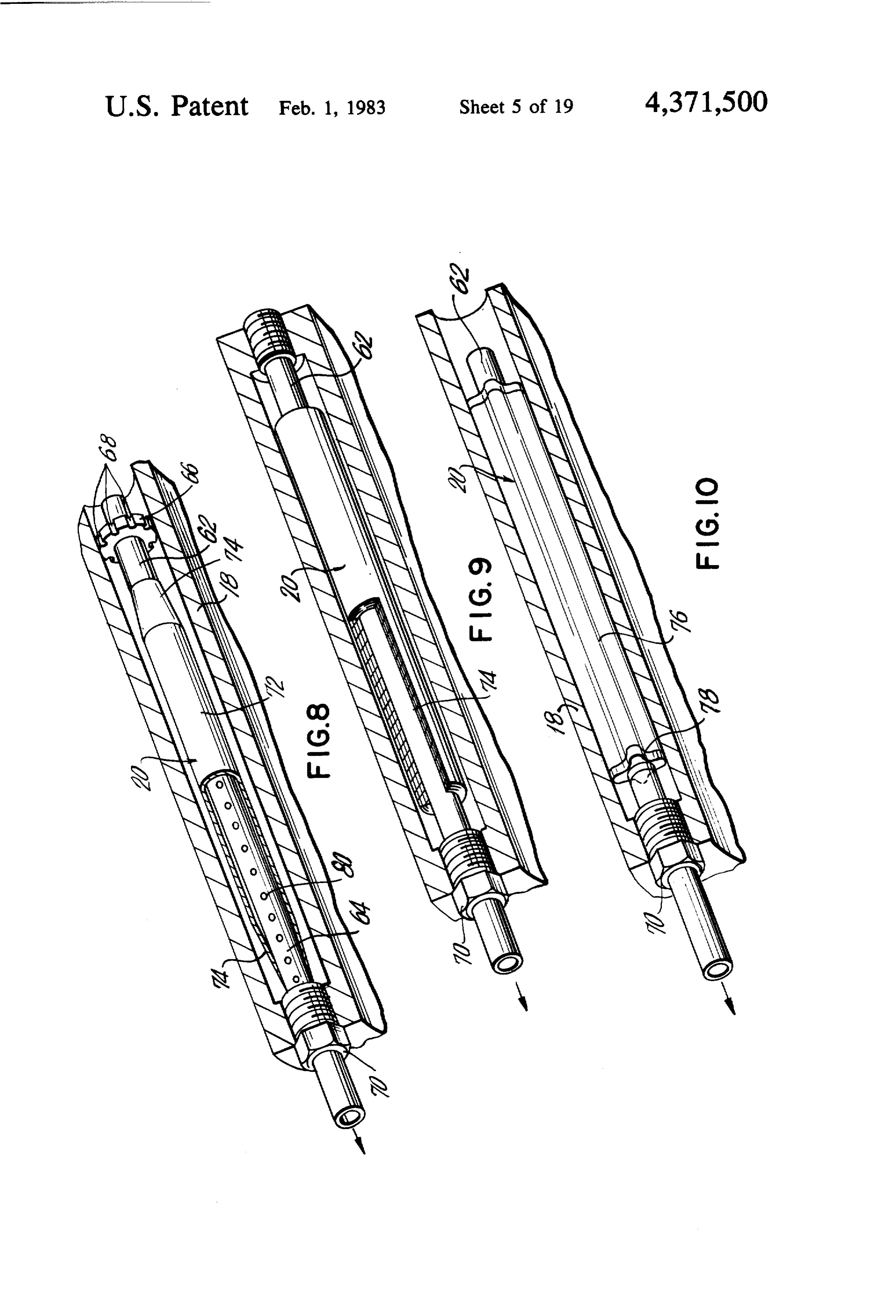
FIG. 8 is a longitudinal sectional view of a tube of the producing reactor containing still another embodiment of the cata needed, as needed. hydrogen from water upon demand, where lyst system of the invention. The system 10 includes a cylindrical reactor 12 about which
FIG. 9 is a longitudinal sectional view of a tube of the generator 14 in which steam is a cylindrical boiler or steam reactor containing still another embodiment of the cata- 15 12. The reactor 12 has a heat is generated for the reactor lyst system of the invention. generating chamber 16 FIG. 10 is a longitudinal sectional view of a tube of disposed centrally of a plurality of longitudinally ex tending, circumferentially spaced zones in the form of the reactor containing still another embodiment of the eight bores or tubes 18a-h having a catalyst 20 in each catalyst system of the invention. tube. At each end of the tubes 18a-h are transverse FIG. 11 is an end view of the upstream end of the 20 passages 22a-d-25a-d and radial passages 26a-h and reactor of the hydrogen generating system. 28a-h for selectively connecting the tubes 18a-h with FIG. 12 is an end view of the downstream end of the cooling means of the hydrogen generating system. each other, with the surrounding atmosphere, and with FIG. 13 is a cross-sectional view of the cooling means the steam generator 14. As shown, a network of con of the hydrogen generating system taken along the lines 25 duits, generally identified herein by reference number 13-13 of FIG. 12. 30, conveys fluids to and from the reactor 12 and boiler FIG. 14 is a planar view, diagrammatically illustrat 14.
ing the interrelationship between the components and STEAM GENERATOR operation of the system shown in FIGS. 1-2, and in cludes metering devices at the upstream end at each of 30 The steam generator or boiler 14 includes an annular the reaction tubes. chamber 32 which extends the length thereof for receiv FIG. 15 is a perspective view of another embodiment ing water and generating steam for the reactor 12. Ex of a hydrogen generating system of the present inven tending through the boiler 14 is a central opening 34 for tion. slidably fitting the boiler 14 about the central portion of FIG. 16 is a cross-sectional view of the reactor of 35 the reactor 12 where it is secured thereto by flanges 36. FIG. 15, taken along the lines 16-16, wherein a second A conduit 38 is connected into the lower portion of set of transverse passages are shown for interconnection the chamber 32 for conveying water from a source (not of the illustrated reactor tubes. shown) to the boiler 14 through a control valve 40. On FIG. 17 is a planar view, diagrammatically illustrat the opposite side of the boiler 14, a conduit 42 is con ing the interrelationship between the components and 40 nected into the upper portion of the chamber 32 for operation of the system shown in FIG. 15. conveying steam to the reactor 12. FIG. 18 is a perspective view of a further embodi As shown the boiler 14 includes a pressure relief ment of the hydrogen generating system of the present valve 41, a pressure gauge 43, and a sight glass assembly invention. 45 with an upper valve 47 to monitor the level of the FIG. 19 is a planar view, diagrammatically illustrat- 45 water in the boiler and with a valve 49 for drainage. ing the interrelationship between the components and REACTOR operation of the system shown in FIG. 18 wherein the steam is fed into the catalyst in each of the reactor tubes. In the embodiment of the invention shown in FIGS. FIG. 20 is a planar view also diagrammatically illus 1 and 2, the cylindrical reactor 12 is integral being trating the interrelationship between the components 50 formed of a solid piece of metal with a large longitudi and operation of the system as shown in FIG. 18 nal central bore therethrough which forms the heat wherein the steam is fed about the catalyst in each of the generating chamber 16 and with eight smaller longitudi reactor tubes. nal bores therethrough circumferentially positioned FIG. 21 is a perspective view, partially broken away, about the chamber 16 which form equidistant reaction showing the energy system producing hydrogen fuel 55 zones or tubes 18a-h.
for a boiler. In the illustrative embodiment, a burner 44 is posi FIG. 22 is a perspective view, partially broken away, tioned within the upstream portion of the chamber 16 to showing the energy system of the invention for produc provide heat from combustion derived from the fuel ing hydrogen fuel for a turbine. that issues from the burner 44. This heat is sufficient to FIG. 23 is a side view showing the system of the 60 generate steam from water in the boiler 14 and to facili invention producing hydrogen fuel for a four cycle tate and cause the reactions within the zones or tubes internal combustion engine. 18a-h for the generation of hydrogen. The burner 44 is FIG. 24 is a side view showing the system of the positioned within chamber 16 so that the flame there invention producing hydrogen fuel for the Wankel en from contacts the portion of the tubes 18a-h which gine. 65 contain three catalyst 20. In other embodiments of the FIG. 25 is a front view, partially broken away, of a invention, described hereafter, the heat source required Stirling cycle engine which includes the hydrogen gen for the system of the invention can be provided by erating system. rejected waste heat, or other suitable sources.
Page 24
Extending from the chamber 16 is an exhaust conduit In the embodiment of the catalyst system 20 shown in 45 for conveying the exhaust from the system. FIG, 6, the catalyst 20 is cut from the sheet 46 into a As shown in FIGS. 3 and 4, the ends of the tubes number of discs 60 juxtaposed between the porous end 18a-h (upstream and downstream) are connected in caps 48 and held together by the wire 50 to form the pairs by transverse bores 22a, b, c and d, and 24a, b, c slidably mounted cartridge.
and d, respectively. Each transverse bore extends be As shown in the magnification of the catalyst 20 tween two longitudinal tubes, e.g., upstream transverse (FIG. 7) the catalyst preferably is formed from a pow bore 22a interconnects the upstream ends of longitudi ered metal product defining a web-like, three dimen nal bores 18a and b while downstream transverse bore sional, cellular structure in which the metal provides a 24a interconnects the downstream ends of the same O network of interconnected metal filaments with inter tubes 18a and b. For access, additional upstream and connected, asymmetrical spaces or cells therebetween. downstream transverse bores 23a, b, c and d, and 25a, b, By reasons of the network-like, porous, cellular struc c and dextend from one of each of the interconnected ture, the metal provides large surface areas which are pairs of the longitudinal bores, i.e., 18a, c, e, g, at the reactive sites. The metals which can be used for the upstream and downstream ends thereof through the 15 catalyst include iron, iron-nickel, copper and molybde outer reactor wall. As shown, the transverse bores, e.g., num, palladium, and platinum. Several of these catalysts upstream bores 22a,23a, etc., downstream bores 24a, 25a, etc., are coaxial with the outer access bores, e.g., have been made available by Foammetal Inc. of Wil loughby, Ohio, under the designation foametal, and are 23a and 25a being of greater breadth. described in its 1974 brochure entitled "LOW DEN Also, the reactor 12 includes the radial bores 26a-h 20 SITY FOAMETAL, A Study Of Surface Area, Tex and 28a-h which extend radially outward from each ture, Cell Size And Filament Diameters'.
tube 18a-h at the end thereof, upstream and down stream respectively, through the outer wall of the reac lessInsites, use, the porous catalyst systems 20 provide count which, with elevated temperatures, cause the
Thus, at each end of the reactor 12, the longitudinal 25 steam to disassociate to form hydrogen gas. Where the tubes 18a-h are interconnected in pairs by transverse lyst formed of iron, the catalyst reacts with the steam, e.g., a cata bores 22a-d and 24a-d; are connected to surrounding produce countless sites are oxidized to an oxidized atmosphere by both the transverse access bores 23a-d The decomposition of the steam metal surface and hydrogen gas. and 25a-d and the radial bores 26a-hand 28a-h; and are will passing therethrough continue until the metal essentially adapted to be connected as will be described hereinaf with oxygen at which time the catalyst becomes 30 becomes coated ter, to the steam generator 14 via the radial bores 26a-h wated. To regenerate the countless sites, hydrogen deacti and 28a-h. can Moreover, accessibility and interconnectability are be fed through the tubes 18a-h into contact with the selective. As shown, each of these bores and passages catalyst 20 where the hydrogen reacts with the oxygen have threaded portions for the receipt of correspond 35 on the metal surface to form water vapor and a free ingly threaded plugs 29 having slotted heads for such metal As surface.
will be described hereafter in more detail, decom purposes. As desired, these plugs 29 may be removed for the passage of steam between adjacent tubes, e.g., position of the water to provide freed hydrogen occurs tubes 18a, 18b, etc., for the passage of steam through with the iron catalyst system 20 in one tube 18, e.g., 18a, one or more radial bores, e.g., 26a or 28a, etc., for drain while oxygen is removed from the iron catalyst system age of the tubes 18a-h through the same radial bores, or 20 in the adjacent tube 18, e.g., 18b. In doing so the heat for access to the interconnecting transverse bores, e.g., of the exothermic reaction, which occurs in the tube 18 upstream transverse bore 22a via bore 23a, etc. In the where oxygen is removed from the catalyst 20, is used illustrative embodiment, all the plugs 29 are in place so to increase the oxidation of the catalyst 20 in the adja that pairs of tubes are not interconnected, e.g., 18a is not 45 cent tube 18 which produces hydrogen gas from steam. connected to 18b via upstream transverse bore 22a, and Where the catalyst causes disassociation without re the tubes are not open to atmosphere such as by radial acting with the steam, e.g., a platinum type catalyst, the bores 26a-h. water disassociates to form hydrogen and oxygen gases. How removal of selected plugs 29 provides flexibility In these embodiments the catalyst will not become de for the reactor 12 is demonstrated hereinafter in connec SO activated under normal operating conditions so that tion with several embodiments of the invention. hydrogen gas can by produced in all the reactor tubes,
CATALYST SYSTEMS
In the illustrative embodiments of the catalyst sys
As illustrated in FIGS. 1 and 2, within the tubes tems 20 of FIGS. 8, 9 and 10, the catalysts are formed 18a-h of the reactor 12, are catalyst systems 20 of the 55 from the platinum type metals and alloys of Group invention for facilitating and causing the separation of VIIIB elements, and particularly platinum and palla water vapor into hydrogen and oxygen. dium metals and alloys. These platinum type catalysts In FIGS. 5-10 there are illustrated various embodi are sufficiently porous so as to allow the permeation or ments of the catalyst systems 20. diffusion of hydrogen therethrough while prohibiting In the embodiment of the catalyst system shown in 60 the passage of water vapor and oxygen. These catalysts FIG. 5, there is illustrated the catalyst 20 in the form of form a web-like cellular structure defined by intercon a spirally wound sheet 46 positioned within the tubes nected platinum type metal filaments which prohibit the 18a-h between two hollow end caps 48 held together by passage of the larger water vapor molecules and oxy wire 50 to form a cartridge slidably mounted within gen, but which permit the smaller hydrogen atoms to each tube 18. Each cap 48 has a hollow sleeve 54 having 65 pass therethrough.
holes 56 drilled therethrough for the wire 50 and from Moreover, the platinum type metal catalysts of the which a hollow plug 58 extends inwardly for abutment invention are essentially self-sustaining under normal against the spirally wound catalyst 20. operating conditions. They do not become readily deac
Page 25
tivated. They can remain active for extremely long In an embodiment of the catalyst system 20, such as periods of time. shown in FIG. 9, the steam can be fed into conduit 62 As shown in FIGS. 8-10 the catalyst systems 20 in and the hydrogen can diffuse through the hydrogen clude a conduit 62 which extends through the catalyst permeable central portion 64 and catalyst 20 into the and which is slidably and removably secured and posi- 5 reactor tube 18, while the remaining fluids pass down tioned within a reactor tube 18. The conduit 62 has a stream through the conduit 62. central portion 64 about which the catalyst 20 is CONDUIT SYSTEM mounted and through which the diffused hydrogen can pass. As an introduction to the conduit system 30, and in About one end of the conduit 62 (upstream), which 10. addition to the conduits already described, the system extends from the catalyst 20, there is a supporting and 30 conveys fluids to and from the reactor 12 by up metering disk 66 (FIG. 8) having a slip fit with respect stream manifolds 96 and 98 and downstream conduits to the conduit 62 and having a sliding fit with respect to 100a-h, and controls the flow of fluids through the the reactor tube 18. About the outer portion of the disk reactor 12 by a control circuit 102 connected to the 66 are a plurality of U-shaped grooves 68 for directing 15 upstream manifolds 96 and 98.
and metering the passage of steam downstream about In general, there are a pair of manifolds (96 and 98) upstream of the reactor 12, for conveying fluids thereto, the catalyst into the space between the walls of the tube wherein 18 and the outer periphery of the catalyst 20. each manifold has a circular conduit and four About the other end of the conduit 62 (downstream), spoke or branch like conduits which extend therefrom which also extends from the catalyst 20, there is a plug 20 andthewhich are connected to four tubes 18. Specifically: upstream manifold 96 has a circular conduit 104 70 welded to the conduit that is threaded for reception and four inwardly extending L-shaped curved con by a correspondingly threaded end of the reactor tube duits 106, 108, 110 and 112 threadably and remov 18 for positioning and securing the catalyst system 20 in ably connected to longitudinal bores 18a, c, e and g a gas tight relationship in the reactor 12. 25 in a fluid tight relationship (See FIGS. 1, 2 and 11); In the illustrative embodiment shown in FIG. 8 the and hydrogen porous platinum type metal catalyst 20 is in the upstream manifold 98 has a circular conduit 114 the form of a plurality superimposed tubes 72 where the and four inwardly extending L-shaped curved con openings in each tube generally are non-aligned or duits 116, 118, 120 and 122 threadably and remov asymmetrical to facilitate the separation of the gener 30 ably connected to longitudinal bores 18b, d, fand h ated hydrogen from the other fluids in the reactor tubes in a fluid tight relationship (See FIGS. 1, 2 and 11). 18. As shown, there are two such superimposed hexa The control circuit 102 controls the flow of fluids to gonally-shaped tubes 72 which are fused together and and through the reactor 12 by selectively providing which have ends 74 that are tapered inwardly to the steam to produce hydrogen, and, as necessary, hydro conduit 62 to contain the diffused hydrogen. 35 gen to reactivate the catalyst in the tubes 18a-h. In the embodiment of FIG. 9, the already described catalyst 20 is in the form of a multi-layered spiral wound twoInsets the illustrative embodiment, the tubes 18 operate in of four tubes each. When on stream, hydrogen material bonded together to form a continuous maze of will be generated in four tubes, e.g., 18a, c, e and g, increased surface area for diffusion of hydrogen. while the catalyst 20 will be regenerated in the tubes In the embodiment shown in FIG. 10, the described to 18b, d, fand h, between or adjacent to the first set of catalyst is multi-layered with a central core 76 from tubes 18a, c, e and g. This process will be reversed when which extend a plurality of radial webs or wings 78 the catalyst 20 in tubes 18a, c, e and g becomes deacti along a length thereof to provide the increased surface wated while the catalyst 20 in tubes 18b, d, fand h has area. The catalyst 20 is X-shaped with four radially become regenerated. During each cycle, moreover, the extending webs 78. 45 reaction in the tubes where catalyst regeneration is With respect to the central portion 64 of the conduit occurring will provide heat which increases the amount 62, it can be made of a hydrogen permeable metal, such of hydrogen being generated from steam in adjacent as the platinum type metals (see FIG. 9). In this embodi tubes, ment the ends of the conduit 62 are formed from an In the illustrative embodiment of the invention shown inert non-diffusable metal, such as stainless steel, 50 in FIGS. 1 and 2, the circuit 102 includes a rectangu welded to the central porous portion 64. larly shaped loop above the boiler 14 which has four As shown in FIG. 8, the conduit 62 of the catalyst legs: two transverse legs 126 and 128, and two longitu system 20 also can have perforations 80 in the central dinal legs 130 and 132.
portion 64 thereof for the reception and passage of Centrally connected into the transverse leg 126 is the diffused hydrogen. In this instance the entire conduit 6255 steam conduit 42 with valves 134 and 136 on either side can be made from stainless steel or other inert, non thereof. Correspondingly, centrally connected into the diffusable metals. transverse leg 128 is a conduit 138 which conveys a In the embodiments (FIGS. 8 and 10) the diffused or regeneration agent, such as hydrogen, from a source permeated hydrogen passes through the conduit 62 (not shown) for the regeneration of catalyst 20. Here while the remaining fluids (water, vapor and oxygen) 60 too valves 140 and 142 are connected into the transverse flow through the space between the catalyst 20 and leg 128 on either side of conduit 138.
reactor tube 18 through passages in the other end of the Centrally connected into the longitudinal leg 130 is a reactor 12. pressure gauge 144 for measuring and controlling steam Further, in these illustrative embodiments one end of pressure, and a conduit 146 for selectively conveying each conduit 62 is closed (upstream) so that the incom- 65 steam or regenerating agent to manifold 96. Similarly ing steam cannot flow directly into the conduit 62. centrally connected into the longitudinal leg 132 is a Instead it flows about the catalyst 20 as has been de pressure gauge 148 also for measuring and controlling scribed. steam pressure, and a conduit 150 for selectively con
Page 26
veying steam or regenerating agent to manifold 98. from a source (not shown) into the quencher chamber Typically, the steam supplied to the reaction tubes 176. For conveying the cooling medium from the cham 18a-h can be at a controlled pressure of about 3 p.s. i.g. ber 176, a conduit 212 is connected to the upstream end Downstream of the reactor are the conduits 100a-h plate 180 and a reservoir (not shown). Within the cham connected in fluid tight relationship to the downstream ber 176, the cooling medium flows about the manifold end of the tubes 18a-h for conveying fluids, generated 190 and through the grooves 204 and space 205 about hydrogen, oxygen and water vapor therefrom. From the inner tube 202 to reduce the temperature of the these conduits 100a-h the fluids are conveyed into a reactor fluids collected in the annular chambers 194 and temperature reducing means 152 where the fluids are 196.
collected and cooled. From the temperature reducing 10 For conveying the cooled reactor fluids downstream means 152, a pair of conduits 154 and 156 convey the of the quencher 152 the conduits 154 and 156 extend fluids through gas detectors 158 and 160, which mea from the annular chambers 194 and 196, respectively, sure the yield of hydrogen, and into separators 162 and and through bores 154a and 156a in the end plates 180 164, where the fluids are separated with the hydrogen and 182.
being conveyed to the collectors 166 and 168 and the 15 The downstream gas detectors 158 and 160 provide a other fluids being conveyed to collectors or separators control over the productivity of the reactor 12 and the 17O and 172. reactivation of catalyst 20 in the tubes 18a-h. The gas The temperature reducing means 152 lowers the tem detectors 158 and 160 indicate whether hydrogen is peratures of the fluids to increase the yield of hydrogen, being generated within each set of four tubes 18a, c, e Cooling prevents the gases formed from the steam, 20 and g, and 18b, d, fand h. When a gas detector 158 or hydrogen and oxygen, from reforming into water vapor 160 shows little, or no hydrogen is being conveyed or water. The reduction in temperature also makes the through the appropriate conduit 154 or 156, this nor fluids easier to handle downstream. mally indicates that the catalyst 20 in the operatively In the illustrative embodiment shown in FIGS. 1, 2, connected tubes 18 has been deactivated. The sequenc 12 and 13, the temperature reducing means 152 is a 25 ing of valves 134, 136, 140 and 142 in the upstream water cooled heat exchanger or quencher having a shell control circuit 102 then is set to provide hydrogen and which includes a chamber 176 formed by a cylindrical not steam to the appropriate set of tubes to reactivate or housing 178 and upstream and downstream end plates regenerate the catalyst 20 therein. When the gas detec 180 and 182 welded to the inner periphery at the up tor 158 or 160 again provides high hydrogen readings stream and downstream ends of the housing 178. The 30 this indicates that regeneration of catalyst has occurred cylindrical housing includes a series of fins 184 to in and the steam cycle can commence again. At such time crease the surface area for cooling purposes, and the the sequencing of the valves 134, 136, 140 and 142 is upstream and downstream end plates 180 and 182 in reset to shut off the supply of hydrogen to such catalyst clude central openings 186 and 188 therethrough. and to convey a fresh supply of steam thereto. Positioned within the chamber 176 spaced from the 35 In the illustrative embodiment, the gas indicators 158 housing 178 and end plates 180 and 182 for the circula and 160 are read by an operator and the valves 134,136, tion of a cooling medium, such as water, the quencher 140 and 142 are set and reset manually. It is within the 152 includes manifold 190 having a central opening 192 scope of this invention to provide for automatic means therethrough and two outer annular chambers 194 and to open and close the valves 134, 136, 140 and 142 re 196 formed by spaced annular partitions 198 and an sponsive to the detection of hydrogen or other fluids in outer two segmented cover 200 welded thereto. Ex the conduits 154 and 156. Such automatic means can be tending through the central openings 186, 188 and 192 electrical, hydraulic, pneumatic or mechanical, or a of the end plates 180 and 182 and the manifold 190 is an combination of such means.
inner tube 202 which is welded to the inner periphery of Downstream of the quencher 152 and gas detectors the end plates 180 and 182. The manifold 190 also in 45 158 and 160, the cooled fluids are separated with the cludes a plurality of the longitudinal grooves 204 there hydrogen and oxygen ready for use or collection. In the through which, with the space 205 between the inner illustrative embodiment the separators 162 and 164 are tube 202 and the manifold 192 define passages to facili those disclosed in my earlier U.S. Pat. No. 3,967,589. tate the flow and effectiveness of the cooling medium. Each separator 162 or 164 includes a tubular housing Extending from the upstream end of the manifold 190 50 214 in which there is disposed an active microporous there are eight passageways 206a-h therewithin: four asymmetric membrane 216. The membrane 216 is a thin, passageways 206a, c, e and g extend into one annular selectively permeable film having a porous supporting chamber 194 and four passageways 206b, d, f and h substrate which has been rolled to form a tubular asym extend into the other annular chamber 196. In the illus metric microporous membrane. These membranes are trative embodiment the downstream conduits 100a, c, e 55 sold by the Roga Division of Universal Oil Products, and g extend through bores 208a, c, e and h in the up Company, 2980 Harbor Drive, San Diego, Calif. 92101 stream end plate 180 and are connected in a fluid type and are described in its brochure, Membrane Produc relationship into one set of passageways 206a, c, e and g tion of Nitrogen Enriched Air For Fuel Tank Blanket while the other downstream conduits 100b, d, fand h ing Applications; dated September 1974. extend through bores 208b, d, fand h in plate 180 and Extending through each membrane 216 and from the are connected in a fluid type relationship into the other downstream end of the housing 214 is a conduit 218 set of passageways 206b, d, fand h. having perforations 219 (FIG. 14) along the length In use, fluids from the reactor 12 are conveyed which lies within the membrane 216. Also, extending through the conduits 100a-h and into the chambers 194 from the downstream side of each housing 214 is a and 196 via the appropriate set of passageways 206a, c, 65 conduit 220 which opens into space between the mem e and g or 206b, d, fand h. For cooling these fluids, a brane 216 and housing 214.
conduit 210 is connected into the downstream end plate As the fluids are conveyed from the conduits 154 and 182 which conveys a cooling medium such as water, 156 into each housing 214, the pressure of the fluids and
Page 27
the porosity of each membrane 216 is such so as to allowfrom the reactor tubes 18a, c, e and g, wherein the cata only hydrogen to be diffused therethrough. The sepa lyst is being reactivated, through the downstream con rated hydrogen then passes through the perforations duits 100a, c, e and g into the quencher chamber 194. 219 in each conduit 218 and is conveyed downstream The fluids in the quencher 152 are cooled by the water ready for use. flowing therethrough to reduce the temperature thereof At the same time the oxygen and water collected in to inhibit reformation of the gases. As shown in FIG. each housing 214 about each membrane 216 is conveyed 14, from the quencher 152 the fluids in chambers 194 downstream by the conduit 220 where the oxygen can and 196 are fed into the separators 162 and 164 via be separated from the water and used as desired. conduits 154 and 156 for recovering the hydrogen gen As shown in the illustrative embodiment, the sepa 10 erated in tubes 18b, d, fand h, as well as any residual rated hydrogen in each conduit 218 and the oxygen and amounts of hydrogen not consumed in the reaction in water vapor in each conduit 220 can be fed into the regenerating the catalyst 20 in tubes 18a, c, e, and g. In appropriate collectors and separators 166, 168, 170 and each separator 162 or 164 hydrogen diffuses through 172. each membrane 216 and perforations 219 in the cen 15 trally positioned conduit 218 and is conveyed into col
OPERATION
lectors 166 and 168 ready for use. Simultaneously the
Referring first to FIG. 1, at start up, the valves 134, fluids which cannot permeate the membrane 216, e.g., 136, 140 and 142 are closed. Water, as needed, is sup water vapor and oxygen, pass about the membranes 216 plied to the boiler 14 through conduit 38 and fuel is and through the conduits 220 into the separators 170 supplied to the burner 44 and ignited, to thereby pro and 172.
vide heat for the generation of steam and heat for the These concurrent operations, which represent the full tubes 18a-h and catalysts 20 therein. When steam has cycle of operation, will continue until the gas detector been generated, valve 136 is opened and the steam at a 160 for the tubes 18b, d, fand h indicates that hydrogen controlled pressure and flow rate is supplied to a set of is no longer being produced in such tubes in meaningful four tubes, e.g., tubes 18a, c, e and g. via the upstream 25 quantities because of deactivation of the catalyst 20 conduit 146 and manifold 96, wherein the steam is ele therein. At this juncture the other gas detector 158 vated to temperatures at which it reacts with the cata operatively connected to the other tubes 18a, c, e and g lyst 20 in these tubes 18 to form hydrogen and minor will show meaningful quantities of hydrogen being amounts of water vapor and oxygen. These fluids are passed through the conduit 154 which indicates that the conveyed from tubes 18a, c, e and g through the down 30 catalyst 20 in such tubes has been reactivated, ready stream conduits 100a, c, e, and g and into quencher once again to produce hydrogen. The opening and chamber 194 where the temperature of the fluid is re closing of the valves is reversed so that steam is supplied duced by water circulating through the chamber 176 through valve 136 to the tubes 18a, c, e and g as hydro and grooves 204 to inhibit reformation of the hydrogen gen is supplied through valve 142 to the tubes 18b, d.f and oxygen gases. From the quencher 152 the cooled 35 and h, thereby reversing the reactions in each set of four fluids are conveyed into and through the separator 162 tubes.
where only the hydrogen diffuses through the mem Thus, by the practice of the present invention, hydro brane 216 into the conduit 218 and is conveyed to the gen is continuously produced ready for use upon de collector 166 ready for use. At the same time the non mand, where needed, as needed.
diffused fluids (oxygen and water vapor) pass through 40 As an illustrative example of the hydrogen generating the housing 214 and into the conduit 220 and collector system 10 shown in FIGS. 1-2 and 9-14, the reactor 12 170 for further processing, as desired. is about 15 inches in length and 6.15 inches in diameter, This start up operation will continue until the down while the centrally positioned boiler 14 is about 10 stream gas detector 158 indicates that meaningful quan inches in diameter. Typically, the reactor tubes 18a-h, tities of hydrogen are not being generated in the tubes 45 which also are about 15 inches in length, are about 0.875 18a, c, e and g. This reading shows that the catalyst 20 in diameter.
therein has been oxidized and become deactivated. As shown, the water quencher 152 is about 5.0 inches At such time, and now referring to FIG. 14, valve 136 in length and about 10 inches in diameter, and the inner is closed and valve 140 is opened to provide hydrogen tube 202 has a diameter of about 3.125 inches. Within to the tubes 18a, c, e and g via upstream conduit 146 and 50 the quencher 152 the manifold 190 has a length of about manifold 96 to regenerate the catalyst 20 therein. Con 4.0 inches, and an outer diameter of about 6.5 inches. currently valve 134 is opened to provide steam to the Further in the illustrative embodiment of FIG. 14, a other set of tubes 18b, d, fand h, via the upstream con metering device 221 at the upstream ends of each of the duit 150 and manifold 98, wherein the steam reacts with tubes 18a-b is provided which controls the flow of catalyst 20 therein to produce hydrogen gas and minor 55 steam and hydrogen thereinto.
amounts of water vapor and oxygen. In the embodiment where the catalyst becomes deac With these ongoing concurrent operations, the heat tivated and is regenerated as just described, moreover, a from the exothermic reaction occurring in tubes 18b, d, foametal catalyst of iron is used. Where the foametal fand g is used to generate hydrogen occurring in the catalyst of iron is wound in a spiral sheet 46 as shown in adjacent tubes 18a, c, e and g. Also, the amount of fuel FIG. 5, its length can be about 2.0 inches and its diame being supplied to the burner 44 can be reduced because ter can be from about 0.5 to 0.625 inches. Where the of the heat from the exothermic reaction is being used to foametal catalyst of iron is the form of a series of juxta generate hydrogen. posed discs as shown in FIG. 6, each disc can be about From the reactor 12 the generated hydrogen and 0.125 in thickness and the combined length of the juxta minor amounts of oxygen and water vapor are con posed discs also can be about 2.0 inches in length. veyed from tubes 18b, d, fand h through the conduits Whether the catalyst 20 is in the form of a sheet or 100b, d, fand h into the quencher chamber 196. Simulta discs, the temperature of the steam in the reactor is neously, fluids, water vapor and gases, are conveyed raised to about 1000 F-1800' F., at which tempera
Page 28
ture, and with such catalysts, the steam disassociates pressure is sufficient for passage of steam through the and hydrogen is generated. interconnected tubes 18a-h and for disassociation of In the practice of the invention the required quanti steam to hydrogen.
ties of fuel for the burner 44 and the regenerating agent From the conduit 42 the steam initially flows through for the deactivated catalysts are substantially less than the radial bore 26th and into the adjacent end of the the hydrogen generated, resulting in an efficient system. reactor tube 18h. The steam within the tube 18h is raised As will be described in the next several embodiments, to disassociation temperatures of about 1000' F. to platinum type catalysts, which normally do not need 1800 F. by the burner 44 and with the platinum type regeneration, can be used to achieve even greater effi catalyst system 20 effects disassociation. As previously ciencies. O explained, only hydrogen is allowed to diffuse through
the platinum type catalyst 20 and into the catalyst con duit 62 for flow from the reactor 12 through conduit
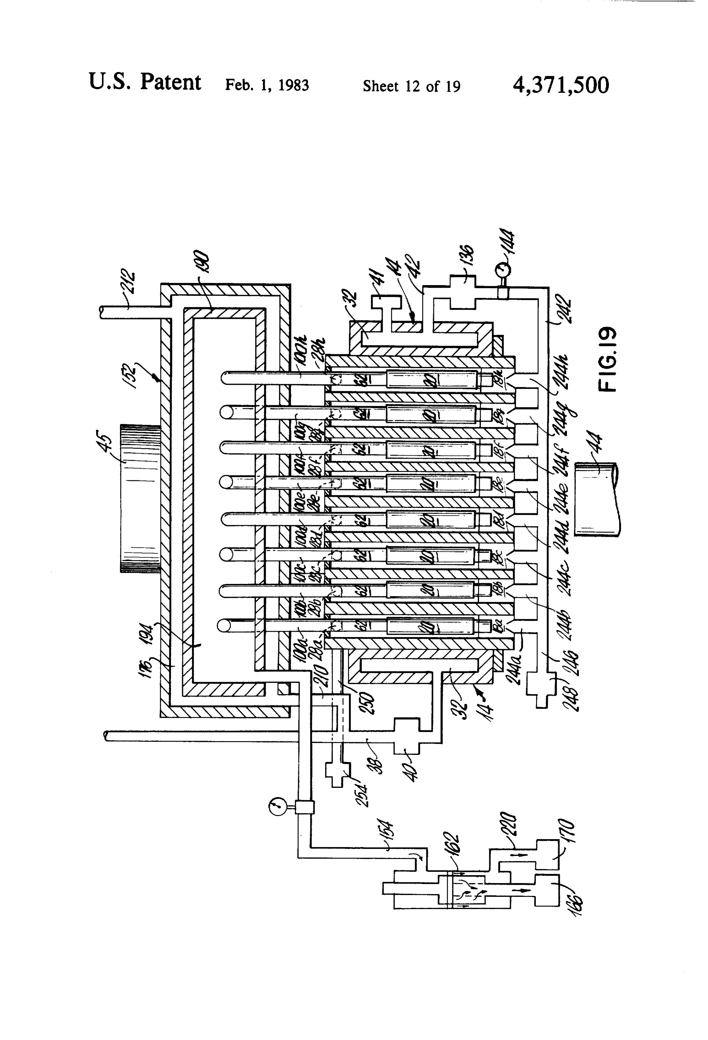
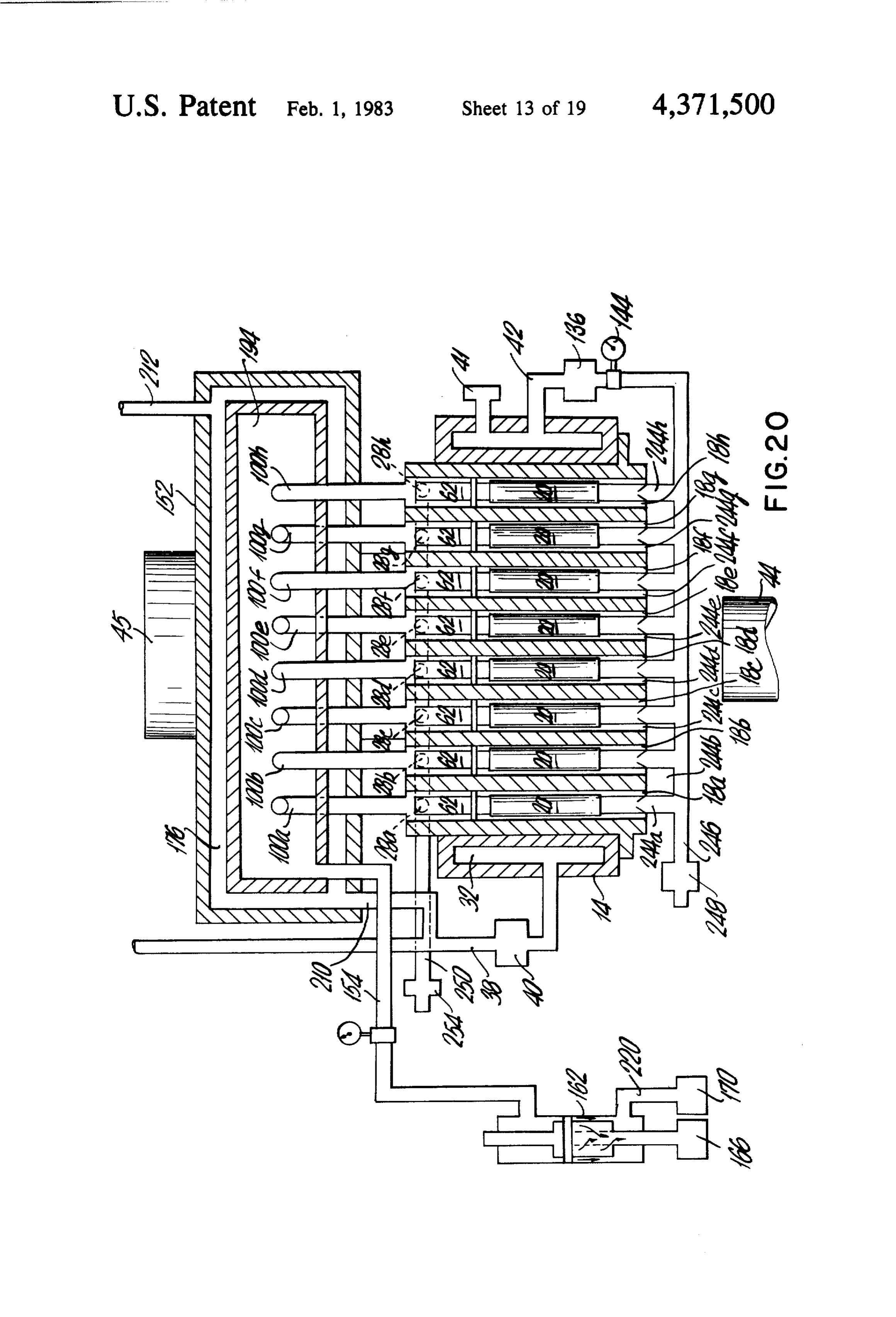
Referring generally to this and other embodiments of 100h into the water quencher 152. At the same time the the invention hereinafter described, like reference num steam, which has not disassociated and the oxygen from bers refer to like parts of the system which have been 15 the disassociation steam, flows about the catalyst 20 to already described. the other end of the reactor 12 and through the trans In the embodiment shown in FIGS. 15-18, steam is verse bore 22d and into the reactor tube 18g where the fed from the steam generator 14 into the downstream process is again repeated. As shown by the arrows indi end of the reactor 12 wherein the steam flows in a ser cating the flow of steam, any remaining steam and disas pentine path through interconnected tubes 18a-h con O sociated oxygen moves in a serpentine path through the taining platinum type catalyst systems 20. remaining tubes 18f-18a and transverse bores 22c-a and As shown in FIG. 15, steam is conveyed to the down 24g-e for further disassociation. The diffused hydrogen stream radial bore 28h of the reactor 12 by the steam in the conduits 62 and in the tubes 18a-h flows as indi conduit 42 which includes a valve 222 and pressure cated from the reactor 12 through the conduits 100a-h gauge 224 that monitors and controls the pressure and 25 into the quencher chamber 194. At the same time resid flow of steam therethrough. ual steam and disassociated oxygen in the last tube 18a To provide the serpentine path for the flow of steam are conveyed from the downstream end of the reactor within the reactor 12, a second set of transverse bores 12 through reactor bore 226 into a conduit 228 con 24e–h in the downstream portion of the reactor 12 con nected thereinto in a fluid type relationship. A valve 230 nect alternate pairs of longitudinal reactor tubes, i.e., in the conduit 228 regulates the flow therethrough by 18b-c, 18d-e, 18f g and 18h-a (See FIG. 16). throttling, to control, by back pressure, the pressure of Taken together the most downstream transverse bore the fluids within the reactor tubes 18a-h and optimize 24a-d, shown in detail in FIG. 4, connect the longitudi the generation of hydrogen therein, nal tubes 18a-h in pairs: 18a-b, 18c-d. 18e-f and 18g-h As illustration, each of the conduits 62 of the catalyst while the next downstream transverse bores 24e-h, 35 systems 20 also can be connected at their other ends, in shown in detail in FIG. 16, connect the longitudinal a fluid type relationship, with a manifold 231 which bores 18a-h in pairs: 18b-c, 18d-e, 18f g and 18h-a, includes a control valve 232. In use, this control valve As with their couterparts, transverse bores 24e–h also 232 can be opened and closed to provide a positive or are threaded and are connected to threaded, transverse negative pressure, as desired, for urging hydrogen gas access bores 25e-h. In each of these bores, moreover, in the catalyst conduits 62 into the quencher 152 or for removable plugs 29 are provided. exhausting gases from the catalyst conduits 62 through In this embodiment platinum type catalyst systems 20, the manifold 231.
such as illustrated in FIGS. 8-10, can be used, In addition, downstream of the quencher 152 the As has been previously explained with a platinum cooled hydrogen gas can be fed into and through the type catalyst, deactivation normally does not occur and 45 previously described separator 162 to further ensure the regeneration is, therefore, not required. Accordingly, separation of hydrogen from any residual fluids which feeding steam and a regenerating agent to a particular may have diffused through the platinum type catalyst tube 18 or set of tubes 18, on an alternating basis, is not along with the hydrogen.
needed. Also, downstream of the reactor 12, the FIGS. 18-20 quencher manifold 190 need only have one cooling 50 chamber 194 and there need be only one separator 162 In FIG. 18 there is shown an embodiment of the downstream thereof. In addition, a downstream gas invention with a single upstream manifold 240 that pro detector, such as detectors 158 and 160, shown in FIG. vides steam to the tubes 18a-h for generation of hydro 1, becomes optional because hydrogen will be gener gen with either of the platinum type catalyst systems 20 ated on a continuous basis within the platinum type, 55 shown in FIGS. 19 and 20, catalyst containing reactor tubes 18a-h. Referring to FIG. 18, the system includes the previ As shown in FIG. 17 radial bore 26h has been opened ously described hydrogen generating reactor 12, steam by removing the plug 29 therein and is connected to the generator 14, downstream conduits 100a-h and steam conduit 42 in a fluid tight relationship. At the quencher 152. The steam is conveyed from the genera same time the transverse bores 24e-g and bores 22a-d tor 14 by the conduit 42 to the top of the single up are opened by removing the plugs 29 while the remain stream manifold 240 which includes a circular conduit ing bores (transverse bores 24a-d and 24h and radial 242 and eight inwardly extending conduits 244a-h bores 26a-h and 28a-g) are closed. threadably and removably connected to the reactor In operation the burner 44, or other source of heat, tubes 18a-h, as has been described and illustrated for the effects the generation of steam within the boiler 14 and 65 dual manifolds 96-98 (see FIG. 11). From the bottom of the steam is fed from the boiler 14 to the reactor tubes the circular conduit 242, a conduit 246 and valve 248 18a-h through the conduit 42 under a control led rate of are provided for drainage or for conveying gases or flow and pressure, e.g., 3 p.s.i.g. The flow rate and liquids from a source (not shown) to the reactor 12.
Page 29
As shown in FIG. 19 the steam from the conduits Compressed air for the burner nozzle 44 is provided 244a-h flows into the upstream portion of the tubes in this embodiment by a motor driven centrifugal 18a-h and about the platinum type catalyst systems 20. blower 314 having a duct 316 extending from the At the elevated temperatures and pressures previously blower outlet 318 into the chamber 16. Fuel for the described, and in the presence of the platinum type 5 burner nozzle 44 is supplied by the generated hydrogen catalyst systems 20, the steam disassociates into hydro as hereafter described and by fuel lines 319 having a gen and oxygen gases with the hydrogen diffusing supply and return conduits 320 and 322 connected to a through the catalyst into the conduit 62. Simulta fuel pump 324, and a conduit 326 connected to a com neously, oxygen and residual steam flows into the mon fuel-hydrogen conduit 328. The common conduit downstream portion of the tubes 18a-h where they are O 328 extends through the duct 316 to the burner 44 cen removed via a manifold 250 having conduits connected trally positioned at the outlet of the duct 316 in the into the downstream radial bores 28a-h in a fluid tight lower portion of the chamber 16.
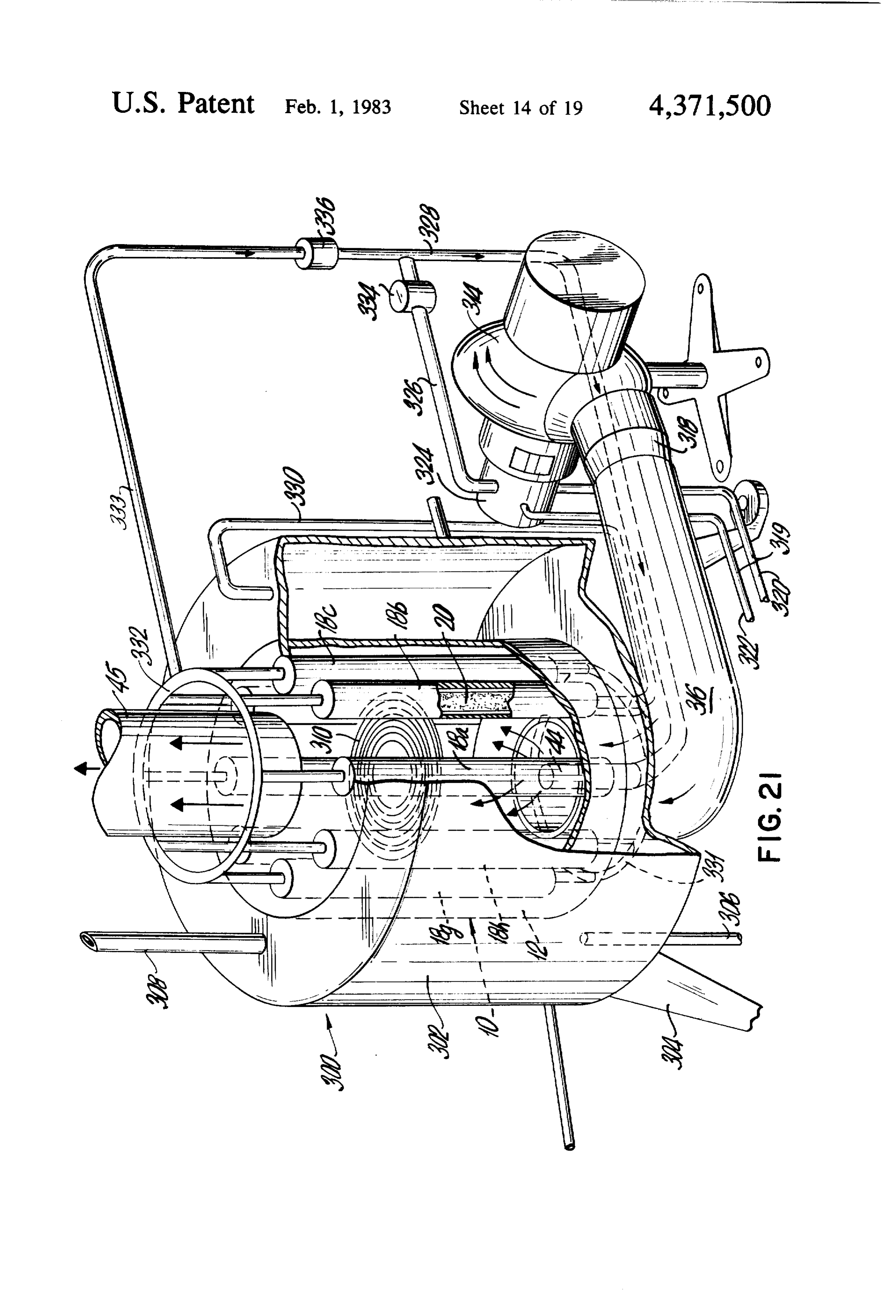
relationship. A valve 254 in the manifold 250 is pro Steam for the reactor 12 is conveyed through a con vided to control flow and pressure in the manifold 250 duit 330 connected to the top of the tank and to the and tubes 18a-h. By controlling the opening in the man 15 upstream side of the tubes 18a-h via a manifold 331 ifold 250 the pressure of the fluids in the tubes 18a–h can which, in this embodiment, is in the lower portion of the be increased or decreased for optimizing disassociation reactor 12. Hydrogen generated by the reactor 12 is and diffusion of hydrogen through the platinum type conveyed from the top and downstream end of the catalyst systems 20. reactor tubes 18a-h to and through a manifold and a Concurrent with removing oxygen and residual conduit 333 which, in turn, is connected to the common steam from the tubes 18a-h, the hydrogen gas is con conduit 328.
veyed from the reactor 12, through conduits 100a-hand Control means, check valves 334 and 336, are con into quencher chamber 194. The cooled hydrogen gas is nected into the fuel and hydrogen conduit 326 and 333 fed into conduit 154 and, if desired, into and through the to control the flow of fuels to the burner 44. separator 162. 25 During start up, the hydrogen check valve 336 is In the embodiment of the invention schematically closed and the fuel check valve 334 is open. The fuel at shown in FIG. 20, the steam from conduit 42 is fed into the burner 44 is ignited, and with the compressed air the conduits 62 of the catalyst system 20, wherein the supplied by the blower 314 throughout the operation, hydrogen diffuses outwardly into the tubes 18a-h while burns to provide heat for the generation of steam in the the disassociated oxygen and residual steam flows 30 tank 302.
through closed ended conduits 62 into the downstream When the temperature of the water in the tank 302 manifold 250 through interconnecting radial passage has been raised and steam is being generated, it is simul ways 28a-h. In this instance, the diffused hydrogen taneously conveyed from the tank 302 by conduit 308 flows about the catalyst systems 20 downstream and for heating and working purposes, and by conduit 330 into the conduit 100a-h for quenching and separation, if 35 for generating hydrogen. The steam in conduit 330 is desired, ready for use upon demand. fed into the lower (upstream) portion of selected reactor In the following embodiments of the invention, we tubes 18, as previously described, wherein the steam at describe illustrative overall systems which incorporate the super heated temperatures reacts with the catalyst the hydrogen generating systems. These overall systems 20 to produce hydrogen.
include boilers, gas turbines, internal combustion en 40 The generated hydrogen is then conveyed through gines, wankel engines, stirling engines and hydrogen the upper (downstream) end of the reactor 12. At this cells. juncture the hydrogen check valve 336 is opened and THE ENERGY SYSTEM INA BOLER the fuel check valve 334 can be partially or entirely closed so that hydrogen, with or without fuel, is con
Referring first to FIG. 21, there is shown a boiler 300 veyed to the burner 44 via the common conduit 328. within which the energy system 10 of the invention is When on stream, therefore, the generated hydrogen positioned. is the fuel source for the heat that produces steam in the The boiler 300 includes an upright cylindrical tank tank 302 and hydrogen in the reactor 12. 302 on supporting legs 304. Water is supplied to the bottom of the tank 302 by an inlet conduit 306, and 50 THE ENERGY SYSTEM IN A GAS TURBINE steam for heating and working purposes is conveyed In FIG. 22, there is shown the energy system 10 of from the tank 302 from the outlet conduit 308 extending the invention producing hydrogen fuel for operating a from the top thereof. gas turbine 400,
Centrally positioned within the tank 302 is the reactor The gas turbine 400 includes an air compressor 402, a 12, in an upright position, with vertical tubes 18a-h and 55 combustion chamber 404, and a turbine wheel 406 catalyst systems 20 about a vertical heat generating within the chamber 404, wherein the compressed air chamber 16. Extending into the chamber 16 is the and fuel form a combustible mixture which drives the burner 44 providing an air-fuel mixture to the lower turbine wheel 406.
portion thereof. As shown, the catalyst systems 20 are in The compressor 402 and turbine 406 are mounted on the lower portions of the tubes 18a-h and the burning a common shaft 408 which extends from the gas turbine air-fuel mixture from the burner 44 impinges on said 400 and which, when rotated by the turbine wheel 406, portion. To minimize heat loss a baffle 310 is centrally generates mechanical power useful in generating elec positioned within the chamber 16 above the burning tricity.
air-fuel mixture. In the illustrative embodiment the baf Extending downstream from and connected to the fle 310 is a spiral wound coil with its outer periphery combustion chamber 404 is the reactor 12 with its cen secured to the outer wall 312 of the chamber 16, Any tral heating chamber 16 for receiving the hot exhaust residual heat that does escape is exhausted from the gases of combustion before they are exhausted down chamber 16 through the exhaust pipe 45. stream through exhaust pipe 45. About the reactor 12 is
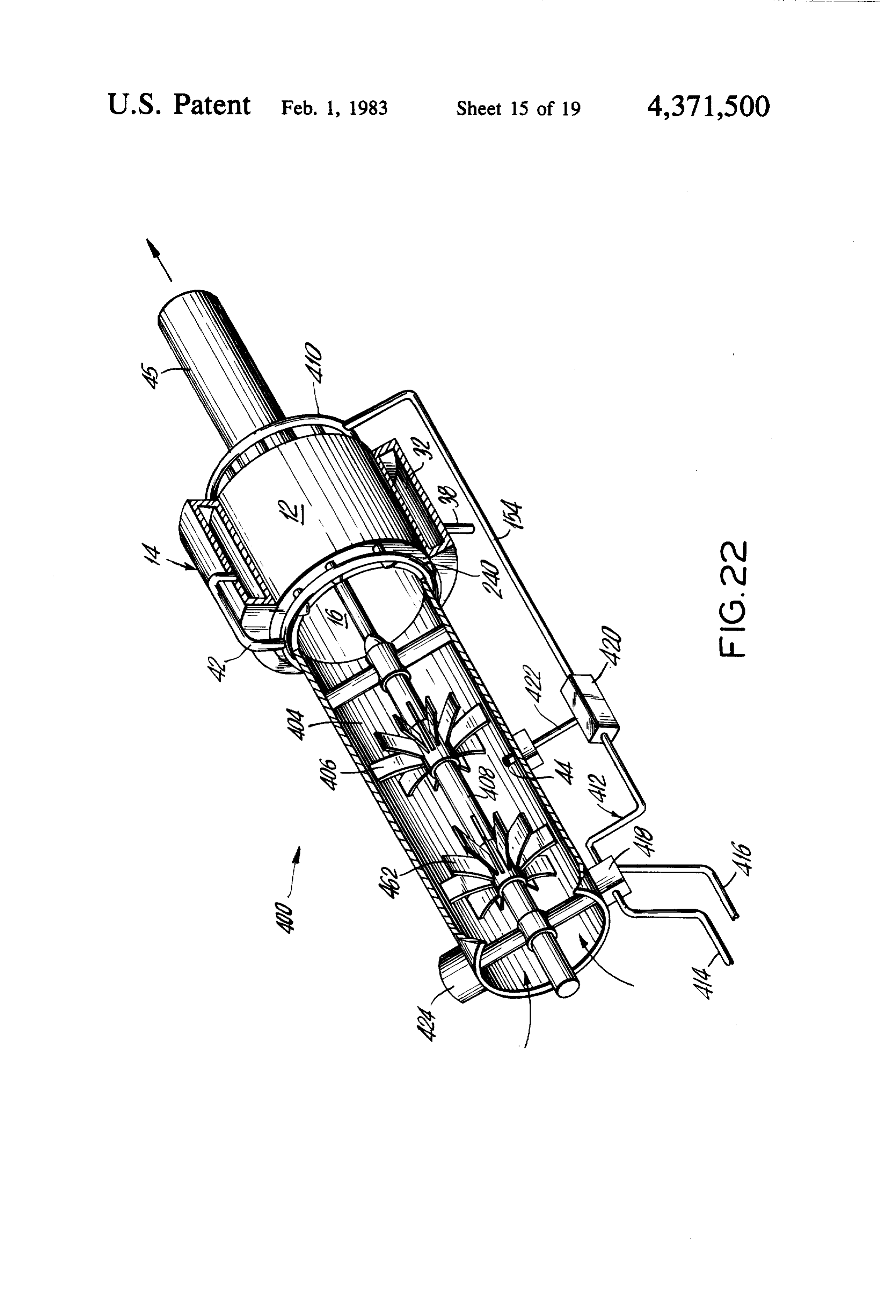
Page 30
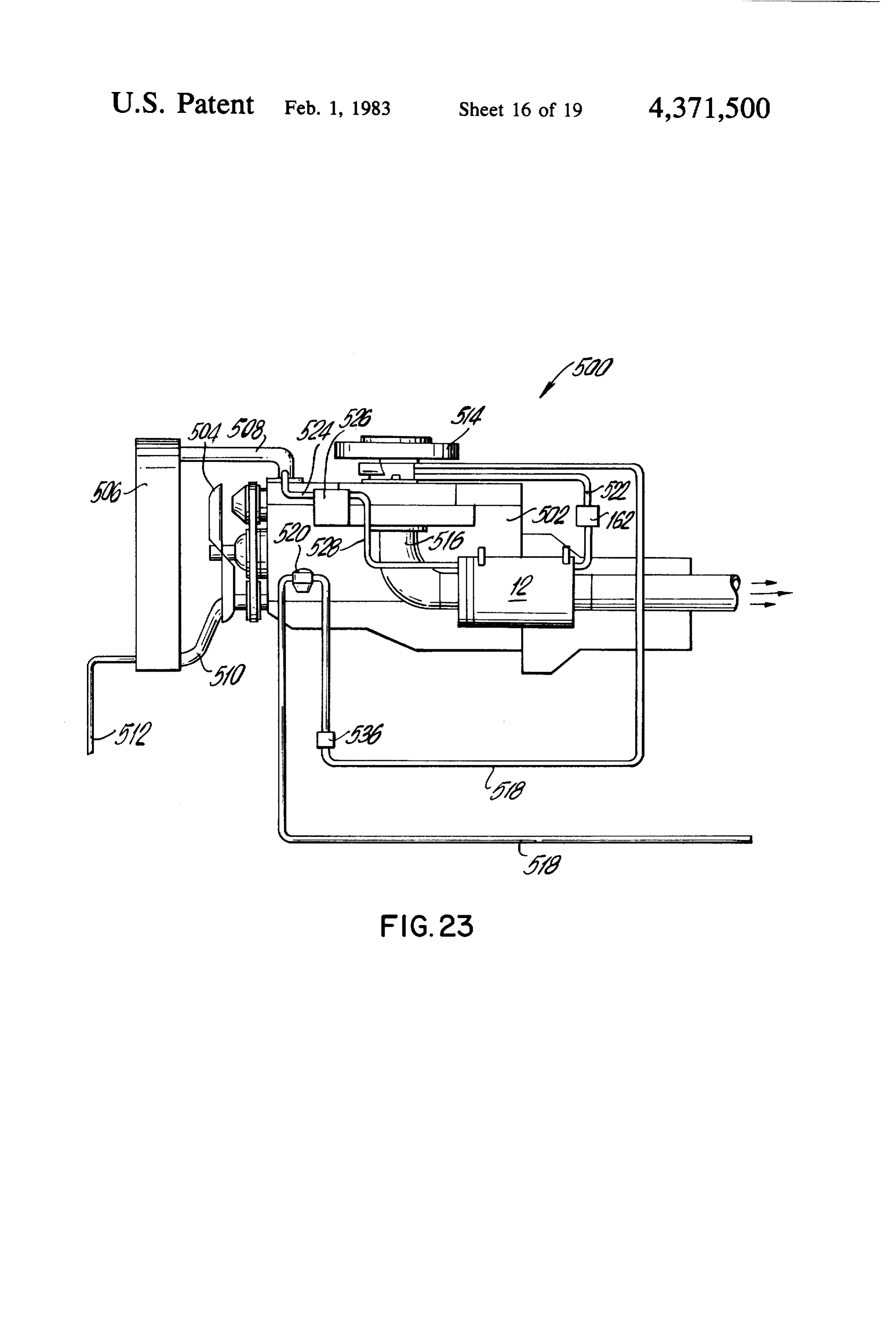
the boiler 14 with its conduit 38 for supplying water and To provide steam for generating hydrogen, an inter with its conduit 42 for supplying steam to the reactor 12 connecting conduit 524 extends from the hot water through an upstream manifold 240. conduit 508 to a flasher 526 connected to the manifold Prior to the generation of hydrogen within the reac 516. In operation, the heat from the exhaust manifold tor 12, fuel is supplied to the combustion chamber 404 516 generates steam in the flasher 526, and the steam is from a fuel line 412 having fuel supply and return con conveyed from the flasher 526 to the reactor 12 by duits 414 and 416 connected to a fuel pump 418. Down conduit 528, stream of the pump 418 the fuel line 412 is connected to Within the reactor 12 hydrogen is generated from the a hydrogen-fuel mixer 420 from which a conduit 422 10 steam provided by conduit 528. The generated hydro extends to the burner 44 in the chamber 404. gen is then conveyed to the carburetor 514 via conduit Initially a conventional starter motor 424 rotates the 522. To insure that only hydrogen reaches the carbure shaft 408 so that air is sucked in and compressed by the tor 514 there is provided a separator 162 in the conduit rotating compressor 402 and conveyed into the combus 522 which, as previously described, allows only hydro tion chamber 404. At the same time fuel is supplied by 15 gen to pass therethrough.
the line 412 to the burner 44 and ignited. The com When hydrogen is being delivered to the carburetor pressed air and ignited fuel mixture burns and rotates 514, a valve 536 in the fuel line 518 can cut off or de the turbine wheel 406 to drive the shaft 408, indepen crease the supply of fossil fuel, as desired. dent of the starter motor 424, for providing the desired Thus, in this embodiment, fossil fuels initially drive
the engine until the engine reaches operating tempera
Once the turbine 400 is on strean, the gases of com tures when hydrogen from the reactor 12 can be used to bustion reach temperatures within the reactor 12 to drive the engine 500.
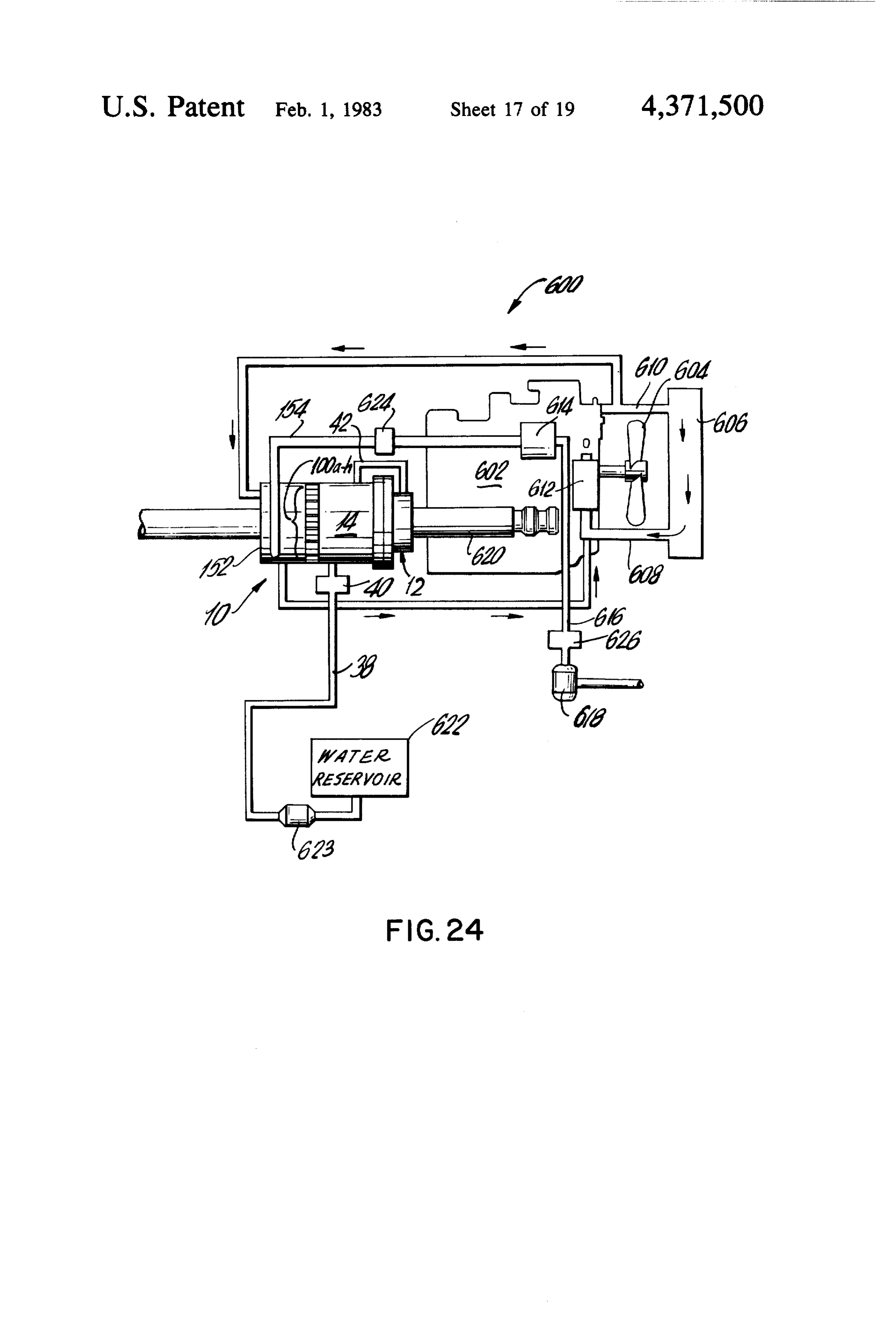
generate steam in the boiler 14 and hydrogen fuel from THE ENERGY SYSTEM FOR A ROTARY steam in the reactor tubes 18a-h, as previously de INTERNAL COMBUSTION ENGINE scribed. Within the tubes 18a-h the steam is elevated to disassociation temperatures in the presence of a previ 25 In FIG. 24 there is shown an energy sytem 10 of the ously described catalyst system to produce hydrogen invention which produces hydrogen fuel for driving a fuel which is conveyed from a downstream manifold Felix Wankel rotary internal combustion engine for 410 and conduit 154 to the hydrogen-fuel mixer 420. vehicles, boats, etc.
With the supply of hydrogen from the reactor 12, the 30 The engine 600 is of a conventional type, and includes amount of fuel needed from the fuel line 412 is reduced a block 602 for the rotor and combustion chamber, not or cut off by the mixer 420 and is conveyed back to the shown, a fan 604 for an air cooled radiator 606 having return fuel conduit 416. Accordingly, the generated conduits 608 and 610 for conveying water to and from hydrogen, with or without fuel from line 412, is deliv the block 602, a water pump 612 in the conduit 608 for ered to the burner 44 from the mixer 420 by conduit 422 35 circulating the water, a carburetor 614 within which the to provide the combustible mixture for the combustion air-fuel mixture is formed for driving the rotor, a fuel chamber 404. line 616 with a fuel pump 618 therein for providing THE ENERGY SYSTEM FOR A FOUR CYCLE fossil fuel to the carburetor 614, and a manifold 620 for INTERNAL COMBUSTION ENGINE exhausting the hot gases of combustion. About the manifold 620 is the hydrogen generating
In FIG. 23, there is shown the energy system 10 being system 10 which includes the reactor 12, the steam used to produce hydrogen fuel for the four cycle piston generator 14, the conduit 38 and valve 40 for providing driven internal combustion engine 500 for land and water to the steam generator 14, the conduit 42 for niarine vehicles, such as automobiles, trucks, farm conveying steam from the generator to the reactor 12, equipment and boats. 45 the water quencher 152 for cooling the hydrogen gener The engine 500 is of the conventional type and in ated within the reactor 12 and conveyed thereto by the cludes an engine block 502 having cylinders and pis conduits 100a-h, and the conduit 154 for conveying the tons, not shown, and a fan 504 for an air cooled radiator cooled hydrogen to the carburetor 614 for driving the 506 having conduits 508 and 510 for conveying water to rotor of the engine 600.
and from the engine block 502, and a conduit 512 for SO In this embodiment the water for the system 10 is providing water to the radiator 506 as needed. As in delivered from a reservoir 622 by pump 623 connected conventional internal combustion engines, there also is a to the conduit 38.
carburetor 514 within which the air-fuel mixture is In operation, fossil fuel initially is provided so the formed for driving the pistons, and a manifold 516 for carburetor 612 via the fuel line 616 and fuel pump 618 exhausting the hot gases of combustion, 55 for driving the rotor of the engine 600. When the engine Initially fossil fuel, e.g., gasoline, is provided to start reaches operating temperatures the valve 40 is opened, and drive the engine 500 until it is at normal operating and the exhaust gases flowing through the manifold 620 temperatures which raises the water to temperatures of and through the system 10 are sufficient to generate about 180° F. to 200' F. The fuel is supplied to the steam within generator 14 from the water supplied carburetor 514 by a fuel line 518 and a fuel pump 520. 60 therein and to generate hydrogen within the reactor 12 Once operating temperatures have been reached, in the presence of previously described catalyst system. hydrogen is generated by the system 10 and is used as a From the reactor 12 the generated hydrogen is con fuel for driving the engine 500. For this purpose the veyed via conduits 100a-h into the water quencher 152 system 10 includes the reactor 12 through which the where the hydrogen is collected and cooled and deliv exhaust manifold 516 extends to provide heat for the 65 ered to the conduit 154. At this time the generated production of hydrogen, and from which conduit 522 hydrogen can be used to drive the rotary engine 600 extends to provide generated hydrogen to the carbure with or without fossil fuel. To effect the transition, the tor 514, control valves 624 and 626 in lines 154 and 616, respec
Page 31
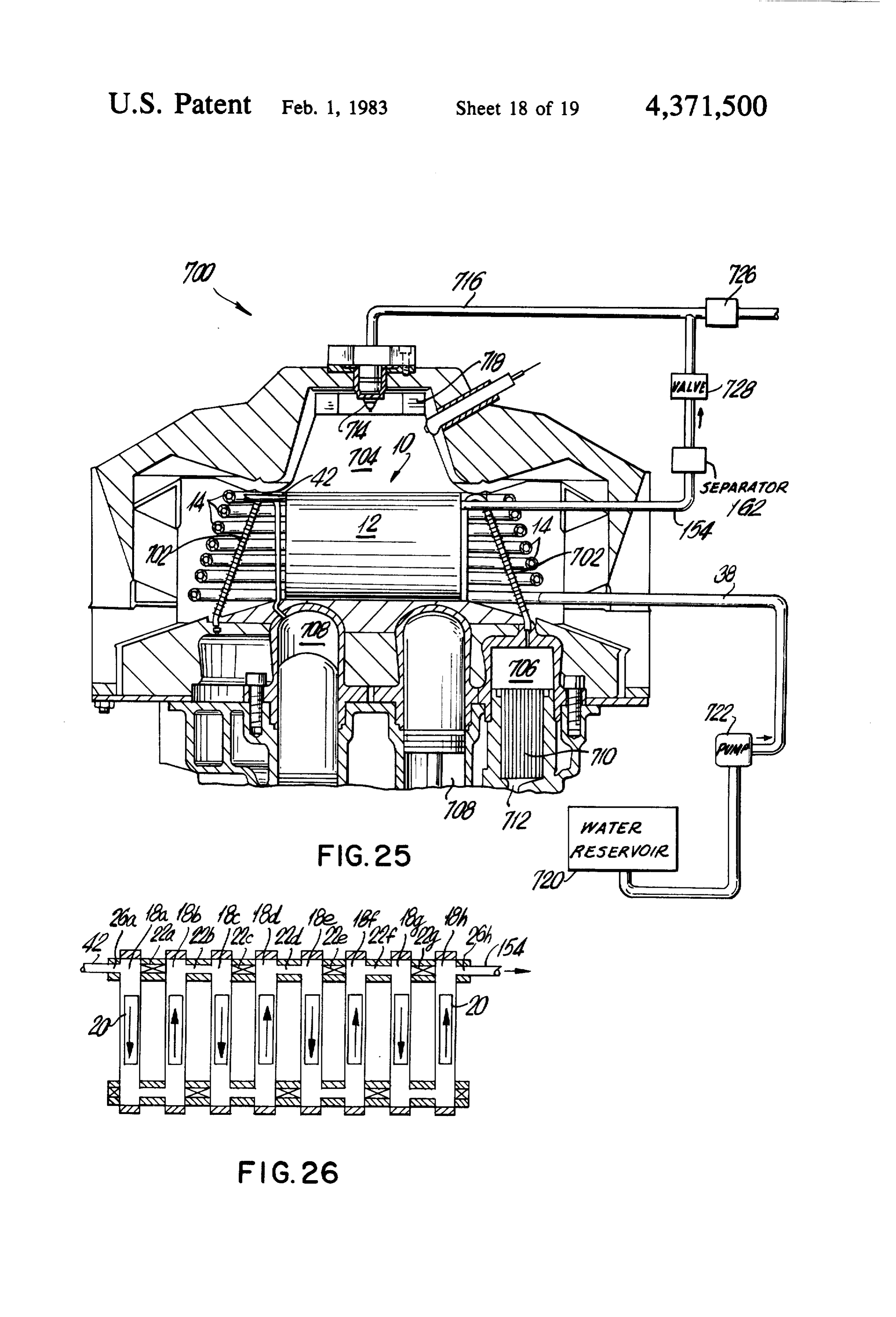
tively, are regulated to provide the desired quantities of the upper chamber 704 concurrently heats the working hydrogen and fossil fuels. gas in the heaters 702 as well as the water in the steam Here again, fossil fuels initially are used to drive the generator 14 and the steam in the reactor 12 by passing engine 600 until hydrogen is generated within the reac therearound and therethrough the generator 14 and tor 12. reactor 12. The hydrogen and other fluids generated in THE ENERGY SYSTEM FOR A STIRLING the reactor 12 flow through the conduit 154 to the sepa ENGINE rator 162 where only hydrogen is allowed to flow downstream. When the hydrogen fuel has reached ap
In general, Stirling engines utilize a working gas, propriate levels, the valve 728 in the conduit 154 is such as hydrogen or helium, in a closed system to drive O opened and the valve 726 in the fuel line 716 can be pistons connected to the drive shaft of the engine, The closed or throttled. In the event that the valve 726 is working gas moves continuously back and forth be closed, then only generated hydrogen will be supplied tween the hot space above the piston in one cylinder to the fuel injector 714 as the fuel for the combustible and the cold space beneath the piston in the next cylin mixture. In the event that the valve 726 in the fuel line der. Between these two spaces the gas passes through a 5 716 is only throttled, then the hydrogen and the other heater which heats the gas, a regenerator which stores fuel will be mixed and supplied to the fuel injector 714 and gives off heat from the gas, and a cooler which as the fuel for the combustible mixture. cools the gas. Consequently, in this embodiment the heat for the As shown in FIG. 25, the Stirling engine 700 includes working gas for the engine 700 is used to generate hy heaters 702 which are positioned in the upper chamber drogen which can be used as fuel for the combustible 704 and which are connected between the regenerator mixture once the engine is at operating temperatures. 706 and upper side of the cylinders 708. Below the THE HYDROGEN GENERATING SYSTEM FOR regenerators 706 are coolers 710 which are connected FUEL CELLS to the opposite side of the cylinders 708 via passage ways 712 (only partially shown). 25 In a fuel cell electricity is generated by a chemical The heat for the heater 702 is provided by the com reaction in which the reactants are continuously fed to bustion of an air-fuel mixture in the upper portion of the the cell as the reaction proceeds. One reactant is a fuel, chamber 704. Fuel is supplied by a fuel injector 714 such as hydrogen, and the other reactant is an oxidant, connected to a fuel line 716, and air is supplied through such as air or oxygen. So long as the reactants, hydro a turbulator 718 which provides flow patterns suitable 30 gen and oxidant, are fed into the cell and the reaction for combustion. The hot exhaust gases from the com product, water, is removed from the cell, the fuel cell bustion of the air-fuel mixture pass about the heater 702 generates power in the form of direct current electric so that heat is transferred to the interior working gas. ity.
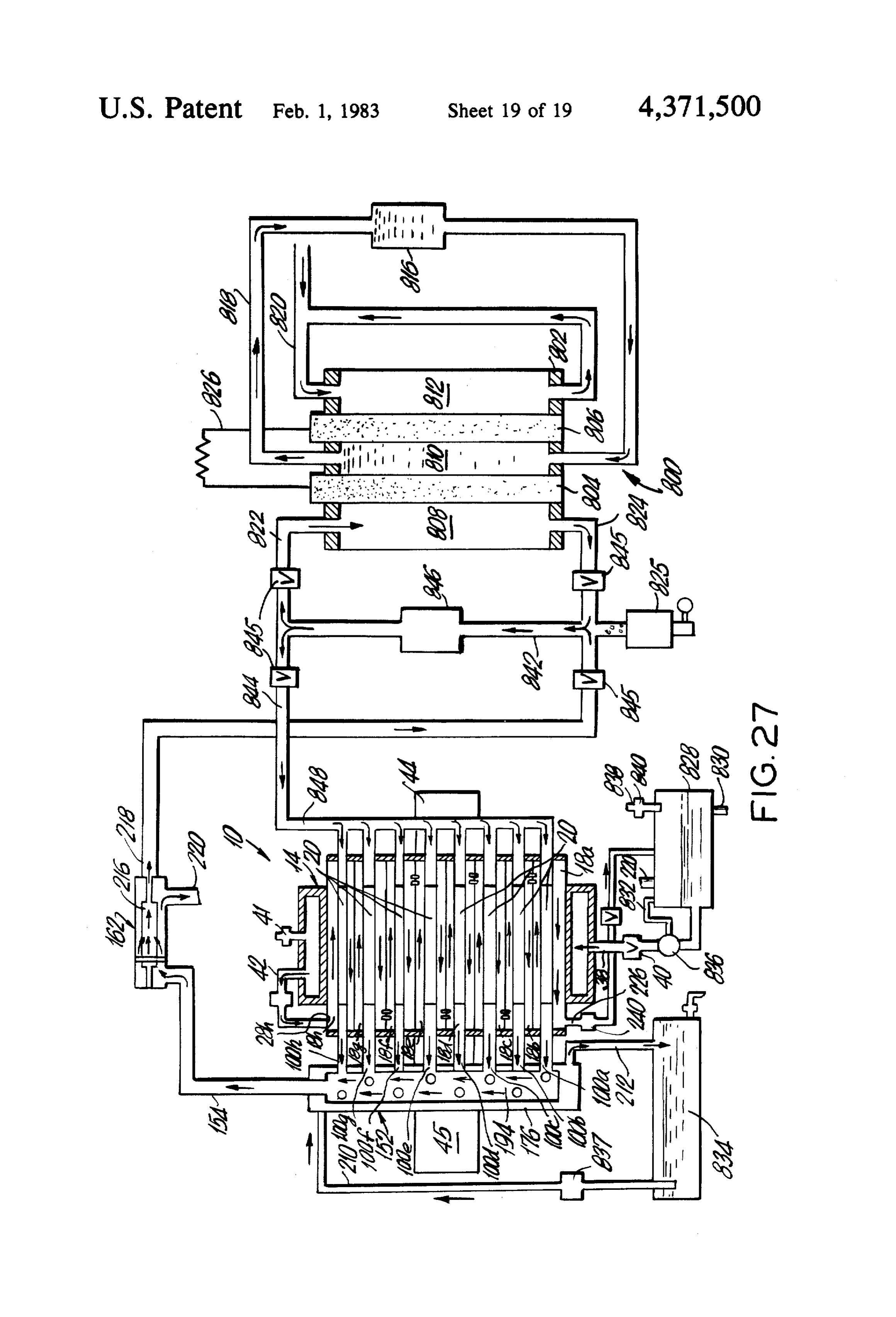
This illustrative Stirling engine is described in greater In FIG. 27 there is illustrated the hydrogen generat detail in a brochure published by United Stirling (Swe 35 ing system 10 which produces hydrogen for a Francis den) AB&CO. Bacon hydrogen-oxygen type fuel cell 800. The system 10 for the engine 700 is positioned within The fuel cell 800 includes a housing 802 and a pair of the upper chamber 704 of the engine 700, and includes spaced electrodes 804 and 806, such as porous nickel the steam generator 14 in the form of a coil and the electrodes. The electrodes 804 and 806 divide the hous reactor 12 positioned within the generator 14. Water is ing 802, into three chambers, 808, 810 and 812. The supplied to the steam generating coil 14 from a water intermediate chamber 810 contains an electrolyte 814, reservoir 720 by a pump 722 through the conduit 38 such as potassium hydroxide, which is conveyed to and connected therebetween. from the chamber 810 and a reservoir 816 through con As schematically shown in FIG. 26, the reactor 12 is duit 818.
in the upright position and includes vertical reactor 45 For the electrical generating chemical reaction, air or tubes 18a-h. In this embodiment there are seven trans oxygen is fed to and unreacted air or oxygen is fed from verse bores at opposite ends of the tubes 18a-h (trans the outer chamber 812 through a conduit 820. Simulta verse bores 22a-g and 24a-g) for interconnecting the neously hydrogen gas is fed to the outer and opposite tubes 18a-h. As illustrated upper transverse bores 22a, chamber 808 through an upper inlet conduit 822, and c, e and g and lower transverse bores 24b, d and fare 50 the unreacted hydrogen gas is conveyed from the cham closed while the other transverse bores (upper trans ber 808 by a lower conduit 824. To remove any conden verse bores 22b, d and fand lower transverse bores 24a, sate a collector 825 is provided in the conduit 824. The c, e and g) are opened. With this configuration, steam direct current electricity generated within the cell 800 is provided through interconnecting conduit 42 and radial conducted between the electrodes 806 and 804 and the bore 26a flows through the reactor tubes 18a-h, and in 55 illustrative circuit 826.
the presence of the catalyst systems 20, in a serpentine In this fuel cell system, the hydrogen gas is provided path. The generated hydrogen and other fluids from the by hydrogen generating system 10 which includes the reactor 12 are conveyed therefrom through radial bore reactor 12 and the steam generator 14. 26h and conduit 154 to the separator 162, which, as Water for the steam generator 14 is provided from a previously described, separates the generated hydrogen reservoir 828. Make up line 830 is connected to a source from the other fluids. As now will be explained, this of water not shown. Pump return line is 832. Water for hydrogen can be used as the fuel for combustion in the the generator 14 is conveyed from the reservoir 828 by chamber 704. a pump 836 through the conduit 38 and control valve 40 Initially the valve 726 in the fuel line 716 is opened into the generator chamber 32.
and the valve 728 in the conduit 154 is closed. Accord Heat from burner 44 (or heat from another source) ingly, fuel, such as fossil fuel or other stored fuel, is raises the temperature in the reactor 12 to about 1000' provided from a source, not shown, to the fuel injector F. to 2000' F., whereupon steam is generated in the 714. The heat from the products of combustion within generator 14 and conveyed to the reactor 12 through
Page 32
the conduit 42, radial bore 28h and into tube 18h. The tures may be made therefrom within the scope of the configuration of the bores within the reactor 12 is simi accompanying claims without departing from the prin lar to that shown in FIG. 17 so that the steam passes cipals of the invention and without sacrificing its chief about the catalysts 20 in the reactor tubes 18h-a in a advantages.
serpentine path as previously described. What is claimed:
Within the tubes 18a-h the steam disassociates into 1. A hydrogen generator comprising: hydrogen and oxygen, and hydrogen passes through the a reactor including a plurality of longitudinal parallel catalysts 20 into the conduits 62, interconnecting con tubes;
duits 100a-h and into the quencher 152. Pump 837 pro porous material supported within each of said tubes, vides cooling water from the reservoir 834 through the 10 for providing hydrogen from water; conduit 210 to a cooling chamber 176, and water is means operatively connected to said reactor for pro returned to the reservoir 834 through conduit 212. viding heat to said tubes to elevate the tempera At the same time disassociated oxygen, and any resid tures thereof for the generation of the hydrogen; ual steam, is conveyed from tube 18a through bore 226 means connected to said reactor for supplying water and conduit 238 to the reservoir 828. As shown the 15 at elevated temperatures to said tubes, wherein, at disassociated oxygen can be removed from the reser the elevated temperatures and in the presence of voir by conduit 838 which includes control valve 840 said porous material, hydrogen is generated; for such purposes. said porous material being positioned in said tubes to From the quencher 152 the cooled hydrogen gas is permit the hydrogen to diffuse therethrough, the conveyed to the separator 162 by the conduit 154 where pores of said material being sufficiently small to only hydrogen is allowed to diffuse through the mem inhibit passage of water for separating the hydro brane 216 and into conduit 218. Any residual oxygen gen from other products of the disassociation of the and water passes about the membrane 216 into the con water; and duit 220 which is connected at its other end into the transverse and radial passages at each end of said reservoir 828. 25 tubes which connect said longitudinal tubes to each Downstream, the conduit 218 is connected to conduit other, to atmosphere and to said water supply 842. In the conduit 842 there is a pump 846 for convey means, said passages including means adapted to ing the hydrogen to both conduits 822 and 844. One receive closures therein so as to provide for selec way valves 845 in conduits 218, 824, 844 and 822 insure tive closing and/or communication therebetween, the flow of hydrogen in the direction indicated by the thereby providing a reactor of optimum opera OWS tional flexibility.
The hydrogen conveyed to conduit 822 enters the 2. The generator according to claim 1 wherein steam fuel cell chamber 808 to generate electricity while the in said tubes and in the presence of the porous material hydrogen in the conduit 844 is used with the pump 846 is elevated to a temperature of from about 1000 F. to to increase the yield of hydrogen in the reactor 12 as 35 about 2000' F. for the generation of hydrogen. will presently be described. 3. The generator according to claim 1 wherein said From the conduit 844 the hydrogen is fed into a mani heat providing means is a central heating chamber, said fold 848 connected to the conduits 62 of the catalyst plurality of longitudinal parallel tubes being located systems 20 in a fluid tight relationship as schematically surrounding said heating chamber, shown in FIG. 27. The pump 846 influences the quanti said water supplying means elevating the temperature ties of hydrogen gas diffused through the catalysts 20 in sufficiently to convert the water to steam, said the reactor tubes 18a-h by creating a negative pressure steam being applied to said reactor; in the conduits 62 relative to the positive steam pressure conduit means connected between said water supply flowing about the catalyst 20 in these same tubes 18a-h. ing means and said reactor for conveying steam to In effect, the pump 846 continually sweeps the diffused 45 said tubes;
generated gases out of the reactor 12. In doing so, the a quencher for cooling generated hydrogen from said equilibrium on the steam side of the catalysts 20, within reactor;
the tubes 18q-h, becomes upset and causes further disas conduit means converted to said reactor and said sociation of the steam into hydrogen and oxygen in quencher for conveying generated hydrogen and trying to maintain equilibrium. SO any other fluids from said tubes to said quencher; In this embodiment, therefore, the generated hydro a separator for separating generated hydrogen from gen is used simultaneously to generate electricity in a other fluids which may be conveyed from said fuel cell and to increase the yield of the generated hy reactor tubes to said quencher; and drogen itself. conduit means connected to said quencher and said In addition to using hydrogen as a fuel, as shown in 55 separator for conveying generated and cooled hy the illustrative embodiments of FIGS. 21-27, the hydro drogen and other fluids to said separator, wherein gen generated by the system 10 of the invention can be the generated and cooled hydrogen is separated used as a chemical in forming products and in chemical ready for use.
processes. For example, the generated hydrogen can be 4. The generator according to claim 3 wherein said used in the manufacture of ammonia, nitrates, amines quencher includes:
and alcohols (e.g., methanol), as well as in the hydroge a cooling chamber for a cooling medium, nation of organic compounds. The generated hydrogen a manifold within said cooling chamber for receiving also can be used in steel making and other metal indus said generated hydrogen and other fluids which tries, the gasification and liquification of coal, the re may be conveyed thereto from said reactor tubes, covery of shale oil, the production of protein foods, and 65 and in total water management programs. opposing means for conveying a cooling medium to Thus, the invention in its broader aspects is not lim and from said cooling chamber and for circulating ited to the specific described embodiments and depar said cooling medium within said cooling chamber
Page 33
and about such manifold to reduce the temperature receive closures therein so as to provide for selec of the generated hydrogen and other fluids to pre tive closing and/or communication therebetween, vent reformation of hydrogen and oxygen which is thereby providing reactor of optimum operational contained in the other fluids and to facilitate han flexibility.
dling of the generated hydrogen. 5 9. The generator according to claim 8 further com 5. The generator according to claim 1 wherein said prising:
porous material in each tube is metallic and contains a quencher connected to said conduit system down innumerable sites on its surface, which, with the ele stream of said reactor tubes which receives the wated temperatures in each tube, effects the generation generated hydrogen and other fluids from said of hydrogen. O reactor tubes, and wherein the generator hydrogen 6. The generator according to claim 5 wherein said and other fluids are cooled; and porous material comprises a cellular structure of inter separating means connected to said conduit system connected metal filaments. downstream of said reactor and said quencher 7. The generator according to claim 6 wherein said which receive cooled generated hydrogen and porous material is selected from the group consisting of 15 other fluids from said quencher, and wherein hy iron, copper, silver, nickel, palladium, platinum and drogen is separated from such fluids ready for use. alloys of iron-nickel and molybdenum. 10. The generator according to claim 8 wherein said 8. A hydrogen generator comprising: reactor includes a combustion means within said heat a reactor including a central heating chamber and a ing chamber and a baffle plate positioned in the central plurality of adjacent longitudinal parallel tubes 20 heating chamber to limit the loss of heat from a combus surrounding said chamber;
a hydrogen permeable porous material contained tion11.taking place therein.
within said tubes which reacts with steam passing temperature elevatingaccording
An generator to claim 8 wherein said means includes means for com therethrough;
a steam generator for providing steam for said reac 25 busting12.
hydrogen.
The generator according to claim 8 wherein said tor;
porous material means operatively connected to said heating chamber a cellular structure in each of said reactor tubes comprises for elevating the temperature within said tubes and of interconnected metal filaments of for supplying heat to said steam generator; iron, which at the elevated temperatures within said a conduit system connected to said reactor and said 30 tubes, reacts with steam to generate hydrogen. steam generator and communicating with said 13. The generator according to claim 12 wherein said tubes for conveying steam from said steam genera reducing agent comprises hydrogen.
tor to the upstream end of said reactor tubes and prising: 14. The generator according to claim 8 further com for conveying generated hydrogen and fluids from the downstream ends thereof; 35 an engine, said temperature elevating means includ means coupled to said conduit system for conveying ing means operatively connected to said engine and a reducing agent to individual ones of said tubes; said reactor for conveying the heat from the prod control means operatively connected to said conduit ucts of combustion from the engine through said system and said reactor for selectively coupling the reactor chamber for elevating the temperature in steam to a first set of said tubes and the reducing 40 said reactor tubes for the generation of hydrogen agent to a second set of said tubes, the steam at the from steam; and elevated temperatures reacting with said porous conduit means connected to said reactor and said material to generate hydrogen, said reducing agent engine for conveying the generated hydrogen reactivating said porous material subsequent to a thereto as the fuel for combustion. deactivation resulting from an interaction with said 45 15. The generator according to claim 14 wherein the steam, and wherein said control means includes engine is a piston driven internal combustion engine. means for alternately switching the steam and the 16. The generator according to claim 14 wherein the reducing agent between the first and second sets of engine is a rotary driven internal combustion engine. tubes; and 17. The generator according to claim 14 wherein the transverse and radial passages at each end of said 50 engine is a gas turbine.
tubes which connect said longitudinal tubes to each 18. The generator according to claim 14 wherein the other, to atmosphere and to said water supply engine is a stirling engine.
means, said passages including means adapted to it
Provenance
- Collection
- Cited prior art
- Original PDF
- patentimages.storage.googleapis.com →
- Filed
- 1980-08-05
- Pages
- 33
- Method
- pdftotext (the PDF's own text layer) + pdftoppm 300dpi page scans
- Source
- Google Patents bibliographic record
- Granted
- 1983-02-01
- Inventors
- Ronald I. Papineau; Unique Energy Systems Inc
- Transcribed from
- patentimages.storage.googleapis.com →