patent · US4369100
Method for enhancing chemical reactions
18 January 1983
Page 1 — bibliographic record
United States Patent (19) (11) 4,369,100 Sawyer (45) Jan. 18, 1983 (54) METHOD FOR ENHANCING CHEMICAL 3,346,472 10/1967 Long ............................. 204/157.1 S
REACTIONS
FOREIGN PATENT DOCUMENTS
76) Inventor: Harold T. Sawyer, 845 Via de la Paz, 458872 12/1936 United Kingdom ......... 204/157. 1 S Los Angeles, Calif. 90272 (21) Appl. No. 285,952 OTHER PUBLICATIONS 22 Filed: Jul. 23, 1981 Crawford, A. E., Ultrasonic Eng., Academic Press, NY,
Related U.S. Application Data Primary Examiner-G. Peters
Attorney, Agent, or Firm-Vernon D. Beehler 60 Division of Ser. No. 837,041, Sep. 27, 1977, Pat. No.
4, 168,295, and a continuation of Ser. No. 144,317, Apr. (57) ABSTRACT 28, 1980, abandoned, which is a continuation-in-part of A method for enhancing chemical reactions in a con
837,041, is a continuation-in-part of Ser. No. 633,818, stantly flowing stream of liquid character fortified with Nov. 20, 1975, abandoned. oxidizing agents, such as air or oxygen or other chemi cal agents, makes use of an inner resonant tube concen 51) Int. Cl. .............................................. B01D 19/10 trically mounted within an outer resonant tube with the 52 U.S. Cl. .......................... 204/157.1 S; 204/158 S; walls of the tubes spaced from each other forming an 423/659 annular passageway for the flow of liquid from one end 58) Field of Search ................................. 423/27, 659; of the passageway to the other. One or more sets of 204/157.1 S, 158 S, 193; 261/DIG. 48 radially spaced ultrasonic transducers are located on the 56) References Cited outside wall of the outer resonant tube thereby to create
an ultrasonic cavitation condition in the liquid as it flows through the annular passageway.
2,876,083 3/1959 Prietl ........................ 2O4/1571 SX 9 Claims, 14 Drawing Figures
Page 2
Drawing sheet — no readable text.
Page 3
Drawing sheet — no readable text.
Page 4
Drawing sheet — no readable text.
Page 5
Drawing sheet — no readable text.
Page 6
new technology. For example, it has been shown that a
METHOD FOR ENHANCNG CHEMICAL typical gold producing company with a recovery rate REACTIONS of 93 percent and with a sales of 50 million dollars annu ally could recover a significant amount of gold should
This is a division of application Ser. No. 837,041, filed the recovery efficiency be increased one percent to a Sept. 27, 1977, now U.S. Pat. No. 4,168,295, which is a value of 94 percent.
continuation-in-part of application Ser. No. 633,818, One of the current problems that occurs during the filed Nov. 20, 1975, now abandoned. This is further a gold leaching process is to provide the proper rate of continuation of Ser. No. 144,317 filed Apr. 28, 1980, oxygen or air flow necessary for oxidation within the now abandoned, which is a continuation-in-part of Ser. O cyanide concentration to recover the maximum amount No. 9,282, filed Feb. 2, 1979, now abandoned. of gold from the ore. The atmospheric air which is Although ultrasonic cavitation of liquids has been introduced at the bottom of the agitator tanks causes an resorted to in the past, as for example cleaning of metal air lift in the form of bubbles which rise in part to the objects, an also for processing purposes as evidenced by surface of the tanks. A portion of the agitation for mix U.S. Pat. No. 3,464,672, the objective has been to trans 15 ing is provided by propeller mixing blades at the lower mit sound energy directly to the liquid. In U.S. Pat. No. portion of the tanks.
3,464,672 material such as rubber normally used as There is commonly a strong resistance to the mixing sound insulation pads because of having virtually no of air or other oxidizing chemical agents with the cya modulus of elasticity, has been used in tubular form as a nide solution during this stirring and airlift operation. support for transducers. Because of its sound deadening 20 The resistance is caused by the surface tension interface property, the rubber tube is incapable of resonance in of the air bubbles and solution. As a result only a por the ultrasonic range and merely holds the transducers in tion and an unpredictable amount of the air in the form a position such that they can drive the sound energy of bubbles is dissolved in the cyanide pulp solution to through the rubber wall to the liquid. Since no ultra provide for oxidation. Furthermore, there is no certain sonic resonance can be set up in the rubber wall, no 25 or known controllable means of determining an accu ultrasonic energy will pass to the liquid except directly rate air flow rate utilizing conventional equipment to at the locations of the transducers, which must be provide the ultimate desired amount of oxidation and placed virtually edge to edge in order to get maximum resultant reaction for maximum metal recovery. application of energy to the liquid. Another problem relates to the time required for In general, techniques and equipment used, for exam 30 dissolution of metals in the agitation circuit. Although ple, in the processing and recovery of such metals as an important part of gold, for example, will dissolve in gold, uranium, silver and copper have been improved the grinding circuit if it is performed in a cyanide solu through better utilization of instruments and controls. tion, there still remains significant undissolved values Over the years there have obviously been improve that require complete oxidation to more fully complete ments in process equipment and techniques used in the 35 the dissolution. The total retention time required in the operation. The introduction of new technology, equip agitation circuit will usually range from 6 hours to 48 ment and methods such as ultrasonic hydrometallurgi hours and sometimes somewhat longer on silver ores. cal treatment of the slurry or pulp during the leaching Part of the problem therefore is the exceptionally long operation, for example, has not been applied. time required for processing and final dissolution in the Improving the effectiveness of existing plant opera agitator circuit.
tions through the use of alternative process technology It is therefore among the objects of the invention to and the implementation of advances should lead to provide a new and improved method for increasing the higher metal recovery and a reduction of metal lost to efficiency of reaction in such a chemical reactor where the tailing dumps. material passing through it is in the form of a slurry or In the case of gold recovery processing, for example, 45 pulp in a chemical solution.
cyanide leaching is generally carried out in large tanks Another object of the invention is to provide a new known as agitators or leaching tanks where the slurry and improved cavitation system and method which or pulp having a consistency of between 30 and 50 effectively and efficiently reduces surface tension percent solids in agitated generally by a combination of which impairs to a degree the desired reaction in the propellers and airlift injection to minimize diffusional 50 slurry while it is being subjected to oxidation. limitations and to provide the oxygen or other oxidizing Another object of the invention is to provide a new agents necessary for oxidation and resultant cyanide and improved method which is effective in improving reaction. reaction between substances in the slurry while the Oxygen is recognized as an indispensable oxidizing slurry is in transit, and without impairing in any way the agent in the dissolution of gold or other metals. Pure 55 rapidity of passage of the slurry from its source to an oxygen is generally too expensive to use. Therefore, ultimate point of deposition.
atmospheric air is the customary source of the required Still another object of the invention is to provide a oxygen gas used as an oxidizing agent. The degree of new and improved cavitation method of relatively sim aeration of the cyanide pulp in gold processing is of ple and inexpensive character capable of being used as a significant importance and concern to the metallurgist 60 part of the system for passing the slurry from its source since some ores, particularly silver ore, require more to its point of deposition, the method being such that it aeration than others. Agitation may be considered as tends to keep itself consistently clean, which operates at stirring or mixing of the pulp with an excess of air in relatively high efficiency, which is capable of readily circular tanks of sufficient capacity to allow the balance being serviced during the course of operation without of the gold to dissolve. 65 need for a shut-down, and which significantly improves The economic incentive for higher recovery effi the efficiency of chemical reaction in the slurry. ciency of metals during the leaching process is substan Another object of the invention is to provide a new tial and suggests improvement through better use of and improved method to complete more fully the disso
Page 7
lution and subsequent recovery of metals in a flowing terials of which various hoses have been made and even Steann. phenolics with a modulus of 500,000 are clearly outside With these and other objects in view, the invention the required range and could not resonate in the ultra consists of the construction, arrangement, and combina sonic range.
tion of the various parts of the device, whereby the 5 The outer flanges 18 have feet 24, which rest on objects contemplated are attained, as hereinafter set resilient isolation supports 20. These in turn are carried forth, pointed out in the appended claims and illustrated on a pad 21 on a stationary bed 25 thereby to mount the in the accompanying drawings. chemical reactor in position.
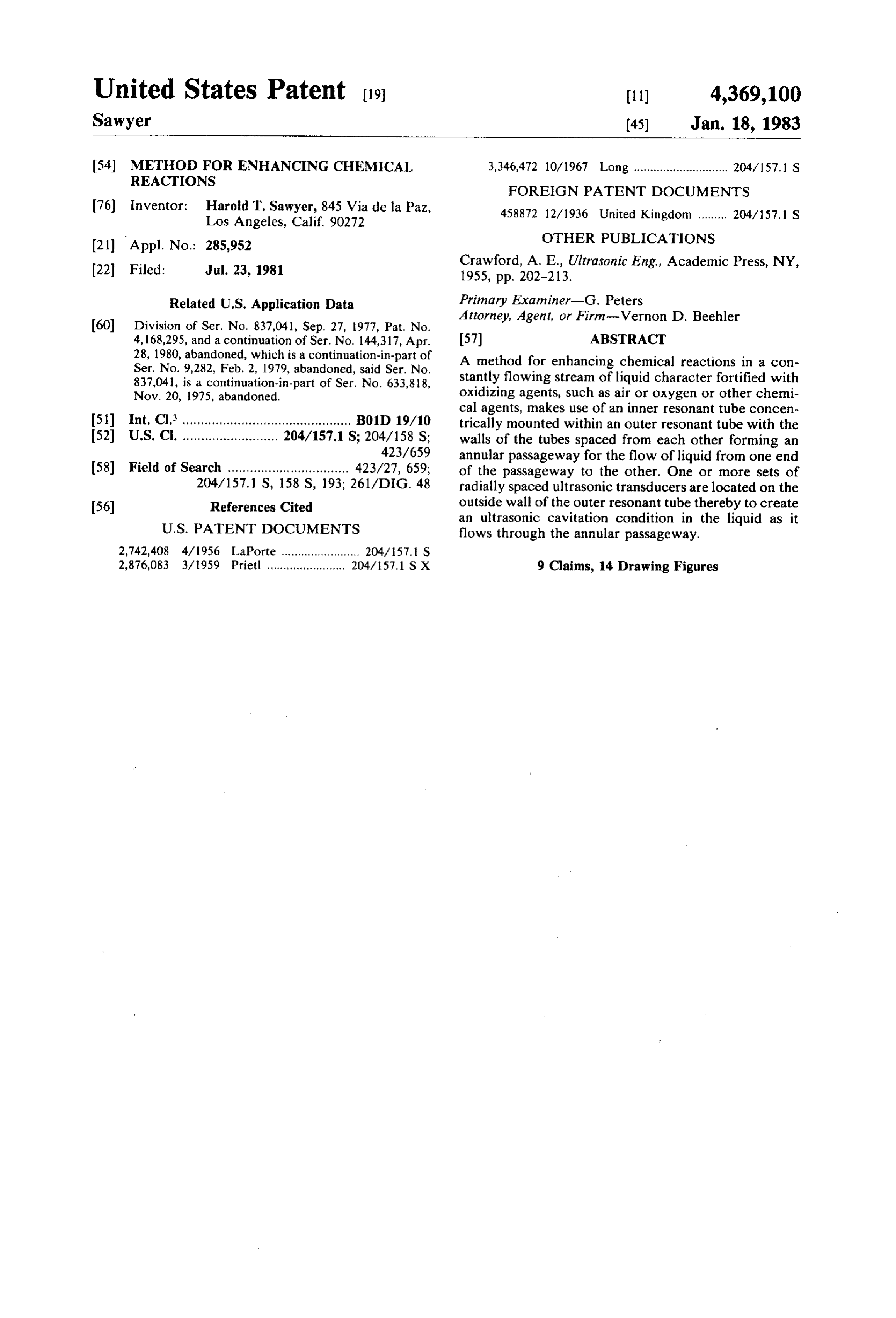
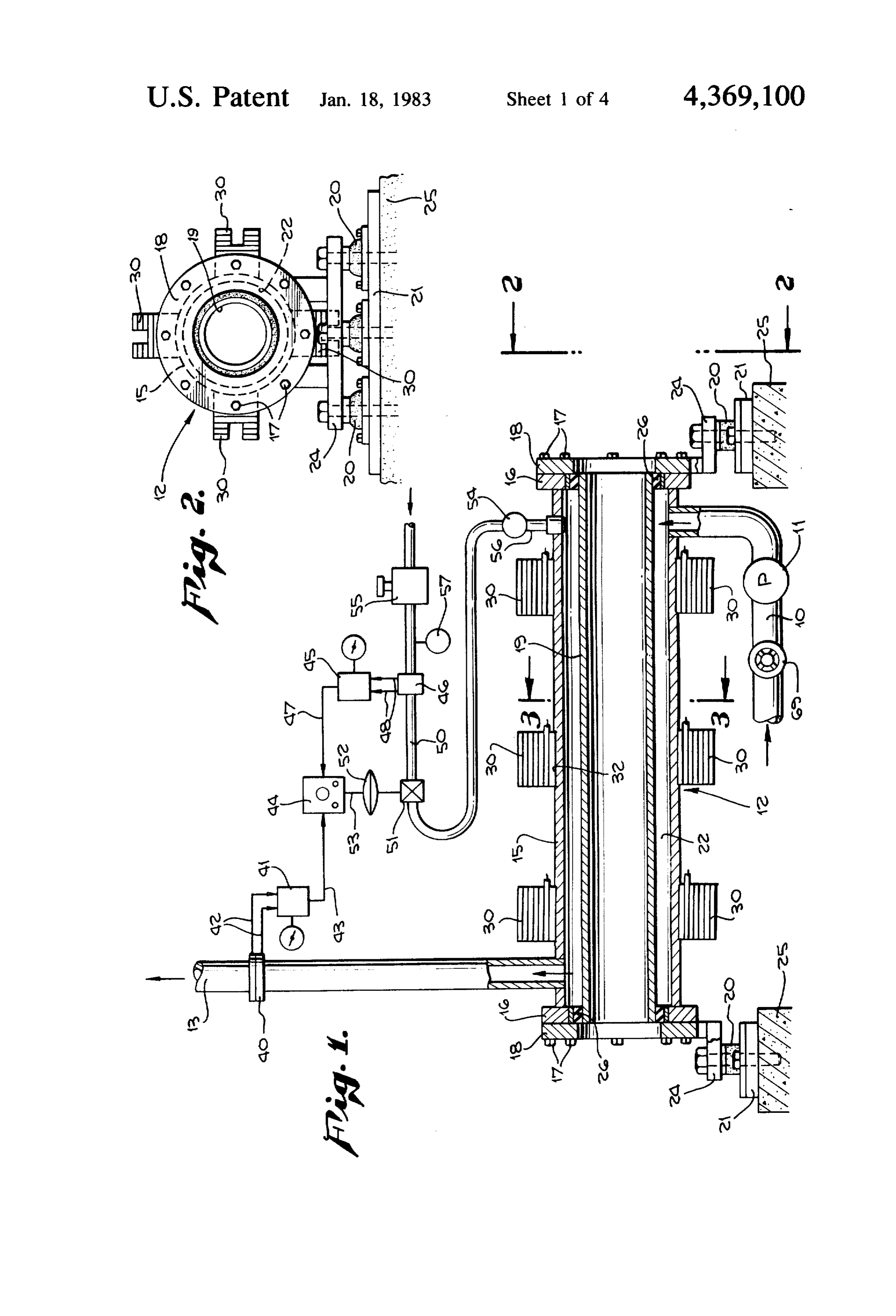
FIG. 1 is a schematic view of the system adopted for As shown, the inner resonant tube has an outside practice of the method applied to a slurry while in tran- 10 diameter substantially smaller than the inside diameter sit, showing the device in section. of the outer resonant tube providing an annular passage FIG. 2 is an end elevational view of the device taken way 22 therebetween. As shown, it is the passageway 22 on the line 2-2 of FIG. I. which the supply conduit 10 is directed into and from FIG. 3 is a cross-sectional view on the line 3-3 of which the discharge conduit 13 flows. F.G. 1. 5 An annular isolation ring 26 at each end serves to FIG. 4 is a diagrammatic showing of the axial nodal isolate and seal the inner resonant tube from the outer pattern. resonant tube 15 and to permit the tubes to be isolated in FIG. 5 is a diagrammatic representation of the cir eSOaCe cumferential nodal pattern. In designating the ring 26 as an isolation ring consid FIG. 6 is a longitudinal sectional view showing the 20 eration must be given to the intensity and wave length location of both circumferential and axial nodes.
FIG. 7 is a schematic representation of the system of the ultrasonic character of the device. The isolation material should normally be much denser than that including an agitator tank.
FIG. 8 is a side elevational view partially broken acceptable to sonic energy in the audible range and may, on occasions, be omitted entirely.
away of another form of the invention. 25 Mounted on the exterior of the outer resonant tube 15 FIG. 9 is a cross sectional view on the line 9-9 of
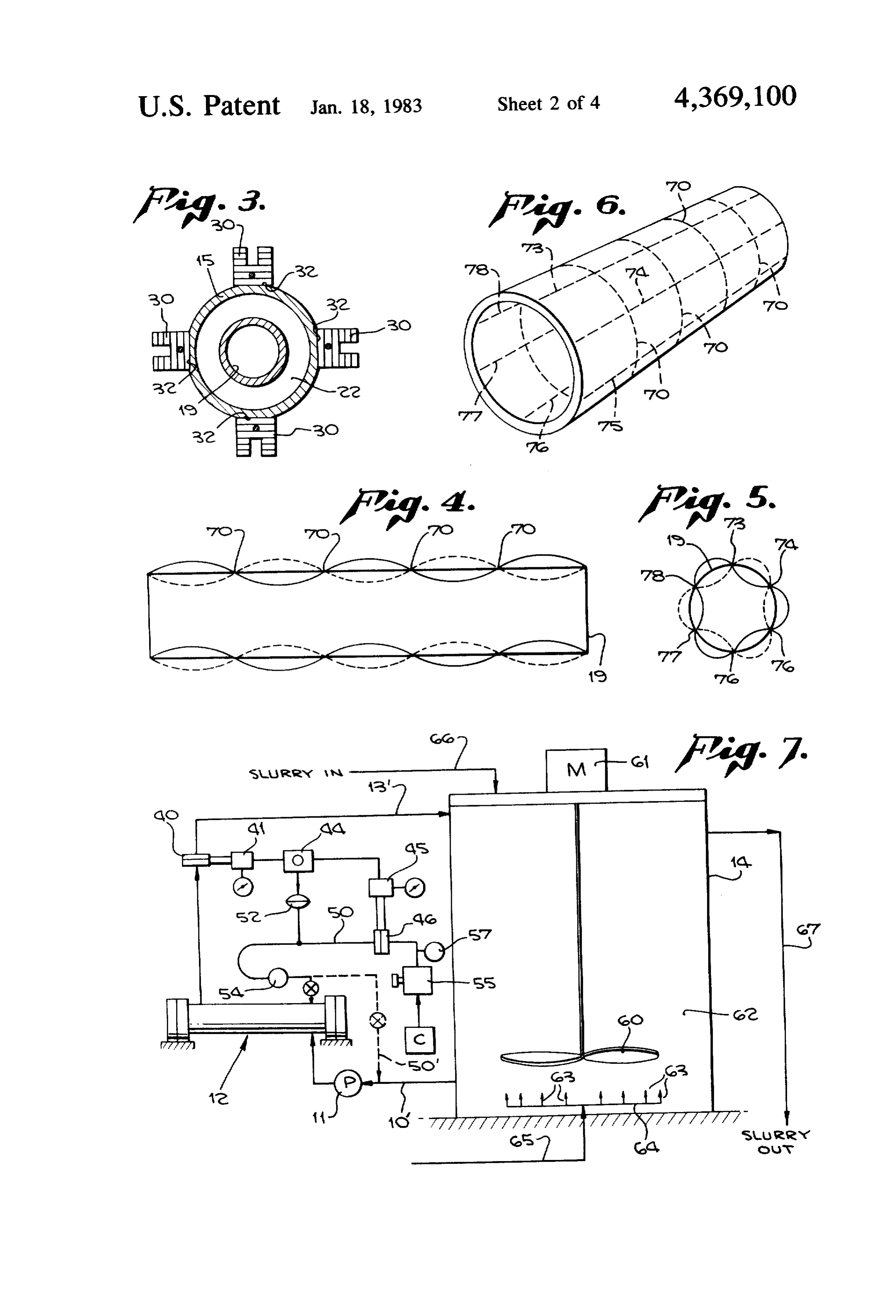
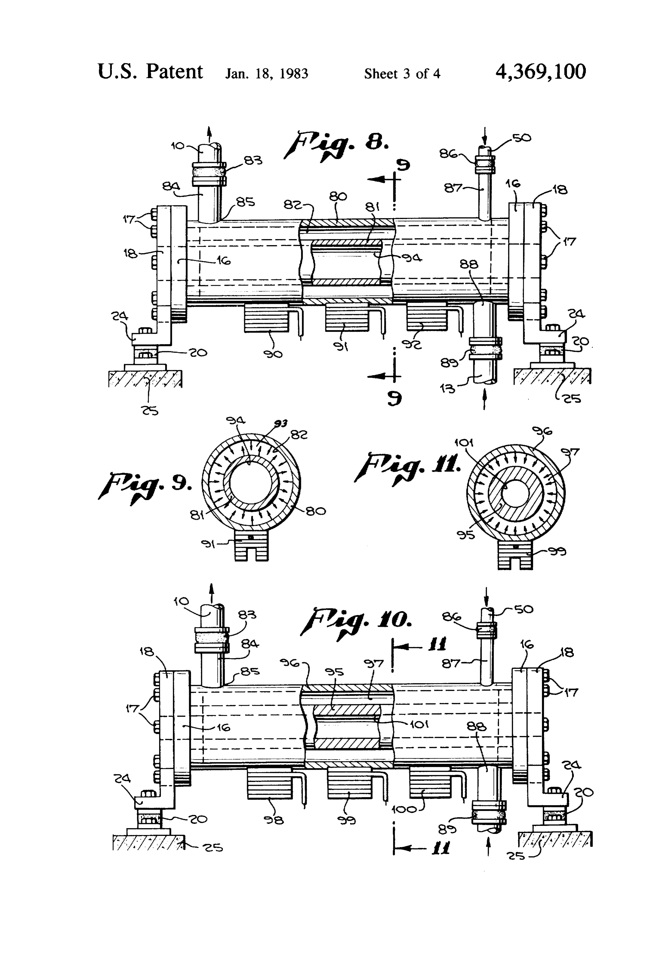
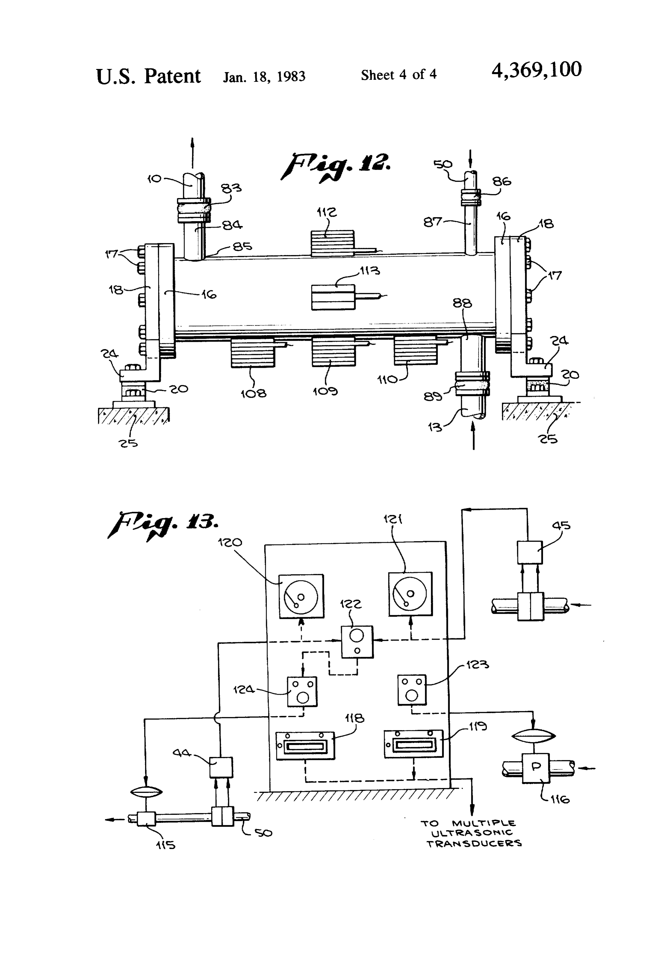
FIG. 8. are three sets of ultrasonic magnetostrictive transducers FIG. 10 is a side elevational view partially broken 30. In the chosen embodiment there are four such trans away of another form of the invention. ducers in each set and all are mounted at an appropriate FIG 11 is a cross sectional view on the line 11-11 of 30 wave length antinodal point. In practice one or more FIG. O. transducers may be used depending on the power re FIG. 12 is a side elevational view of still another form quirement of the system or a multiple number as shown. of the invention. The ultrasonic heavy duty magnetostrictive transducers FIG. 13 is a diagrammatic representation of the con 30 are substantially conventional in their mechanical trol panel and related instrumentation. 35 makeup, and adapted to be supplied with electric cur FIG. 14 is a schematic representation of a gravity rent from their power supply generator and through system including a separator and solvent return system. appropriate leads 31.
In an embodiment of the invention chosen for the Piezoelectric transducers are customarily made with purpose of illustration, there is shown in FIG. 1 a sup a resonant diaphragm at which point the high frequency ply conduit 10 for a stream of substantially liquid mate- 40 sound energy is accummulated and from which the rial, such as a pulp or slurry, which is passed through sound wave energy is projected. In the device herein the system by action of a variable speed pump 11 and disclosed the resonant tube is itself a diaphragm for the evacuated through a discharge conduit 13. A chemical magnetostrictive transducers and irrespective of reactor assembly indicated generally by the reference whether one or a multiple number of transducers are character 12 receives the stream from the supply con- 45 employed the entire tube is set in resonance at the same duit and ultimately passes it to the discharge conduit 13. ultrasonic frequency. The transducers and the entire The discharge conduit may, on some occasions be di length and circumference being in that way activated rected to recirculating the slurry back to the process produces a source of sound wave energy applied con through appropriate conventional means or on occa pletely throughout the entire surface of contact of the sions may pass the slurry to an agitator tank 14 as shown 50 liquid with the resonant tube. A high power transfer of in FGS. 7, from which it can be recirculated back to sound energy is in that way made possible. the supply conduit 10, In the present disclosure, the structure itself, namely The chemical reactor assembly 12 consists of an outer the entire length and circumference of the resonant tube resonant tube 15 having flanges 16 at respective oppo or tubes, as the case may be, provides a diaphragm for site ends bolted in sealed condition by means of bolts 1755 sound emission in the ultrasonic range which generates to respective flanges 18 supporting in part an inner the desired cavitation in liquid flowing adjacent to it. resonant tube 19. By providing dual resonant tubes the liquid passage 22 For a tube like the tube 19 to be resonant it should be is kept narrow and substantially all liquid passes in of resilient stiff material with a modulus of elasticity in contact with the resonant tube exposed surfaces. When the range of from about 30,000,000 to about 21,500,000 60 both tubes are set in resonance by transducer action, or slightly lower. This is recognizably the range for cavitation is produced over an area encompassing the metallic materials such as steel, stainless steel, nickel, entire length and circumference of the liquid media to alloys of copper and perhaps some of the harder alloys be treated.
of aluminium with the possible inclusion of some spe For greater convenience the transducers are shown cially constituted non-metallic materials. The stability 65 mounted on the exterior of the outer tube. For generat inherent in the metallic materials is a highly desireable ing resonance directly in the inner tube the transducers characteristic. Materials such as soft rubber or fiber could be mounted on the interior of the inner tube. The reinforced rubber, or comparable pliable synthetic ma inner surface of outer resonant tube 15 and the outer
Page 8
surface of inner resonant tube 19 are plasma sprayed for mixture solution passing through the reactor chamber corrosion and abrasion resistance. to intense dispersion, mixing, cleaning, and to a chemi To integrate the transducers with the wall of the cal reaction within the confined annular passageway 22. resonant tube, and employ the tube as the transducer In the passageway the mixture is processed under pre diaphragm, the transducers are vacuum brazed directly cisely controlled conditions by very intense ultrasonic to the resonant tube. Flats 32 may be milled on the energy which in turn produces a high energy field of surface of the tube itself at the transducer locations cavitation energy directed in spherical and perpendicu where the brazing is to take place. lar fashion across and through the slurry solution within In the system as shown in FIG. 1 an orifice flange 40 the annular passageway 22 as shown in FIG.3 and as it is provided in the discharge conduit 13 which is ser 10 flows through the reactor chamber.
viced by a flow tansmitter-indicator 41 through leads Since the reactor is a self-contained device which can 42. From the flow transmitter a lead 43 leads to a flow be designed to a wide range of flow rates, it lends itself ratio controller 44. The same flow ratio controller also to choice of locations in the cyanide leaching circuit. As services a second flow transmitter-indicator 45 and desired by the metallurgist for example, an effective orifice flange 46 through leads 47 and 48. As noted, the 15 installation would be to utilize the chemical reactor as a orifice flange 46 is in a line 50 for the introduction of recirculation device for one or more of the holding oxygen or other appropriate oxidizing agent to the sys tanks, whereby flow capacities ranging from 40,000 tem. In the line 50 is an automatic control valve 51, the gallons per hour or higher could be withdrawn continu operation of which is dependent upon operation of the ously from a tank, circulated through the reactor for flow ratio controller 44 acting on a diaphragm valve 20 processing and returned to the agitator tank. In this actuator 52 through appropriate connection 53. manner, the contents of the tank would be recirculated A pressure reducing control valve 55 and companion and processed for controlled oxidation and reaction pressure gauge 57 are located in the line 50 upstream many times during processing. For larger tanks where with respect to the orifice flange 46. At the downstream larger rates of recirculation may be required, multiple discharge end of the line 50 and located within the 25 use of the chemical reactors can be utilized. annular passageway 22 is an aspirator nozzle 56. A FIG. 7 shows the conduit 10' flowing from the agita check flow valve 54 is shown near the discharge of line tor tank 14 which transports the slurry and cyanide 50. Oxygen or other appropriate chemical oxidizing solution to the reactor, the flow rate of which is mea agent flows from the line 50 through the slurry within sured by either a segmental orifice or a flow nozzle and the annular passageway 22. The slurry is forced 30 its transmitter. The pump 11 is shown in the line to through the annular passageway 22 by means of the circulate the pulp solution through the agitator assem pump 11 which is located at the inlet end of the annular bly 12 to the tank 14. The compressed gas flow rate is passageway. A manual valve 69 may be mounted in the measured in turn by the orifice 46 and its transmitter 45. supply conduit 10 as shown. The two flow transmitters 41 and 45 in turn transmit FIG. 7 represents a recirculation system added to the 35 their individual flow rate results to the flow ratio con disclosure of FIG. 1 and shows the chemical reactor 12 troller 44 which automatically regulates control valve and its associated equipment interconnected to, for ex 51 in the compressed air line to proportion and maintain ample, commercial type of propeller agitator or leach a fixed ratio of airflow to pulp solution flow. The flow ing tank 14 for continuous recirculation of the contents ratio controller 44 is equipped with a manual ratio set of the agitator tank for processing by the chemical reac 40 ting to enable the metallurgist to adjust the desired tor 12. value or ratio from time to time as may be required to A process inflow line 66 passes pump or slurry to the maintain optimum oxidation and reaction taking place tank reservoir chamber 62, and an outflow line 67 re in the agitator holding tank closed system in order to turns the processed material to the main process system increase the efficiency of metal recovery. The com circuit. A propeller 60 within the tank driven by motor 45 pressed air may be passed to the reactor assembly 12 61 provides stirring, lift and agitation for the tank's through a shutoff valve 59 shown in solid lines or contents. In addition, the tank is provided with a series through a line 50' and shutoff valve 59' to a point up of air jets 63 located on a spreader 64 at the bottom of stream of the pump 11 as shown by broken lines. the tank and supplied by an auxiliary air line 65. The The resonant tube 15, which is a cylindrical shell, is purpose of the jets is to provide oxidation of the tank's 50 specifically designed to one of the desired axial and material and to also induce an additional air lift for circumferential ultrasonic resonant frequencies that agitation. have been selected for the structure. An example of the The recirculation is provided by a conduit 10' located wave length frequency patterns showing nodes and near the bottom of the tank and a conduit 13 located antinodes referred to for the cylindrical shell is illus near the top portion of the tank. The pump 11 passes the 55 trated in FIGS. 4, 5 and 6. The same description applies material through the chemical reactor and returns the also to the tube 19.
contents to the agitator tank through conduit 13". Employment of the chemical reactor in ore and metal To illustrate graphically the activity of the resonant chemical processing dictates that the cylindrical shell tubes 15 and 19 there is shown in FIG. 4 a resonant be designed for the ultrasonic frequency range chosen pattern which contains four axial wave length nodal preferably at a value between 20,000 and 40,000 cycles points 70. There are also circumferentially disposed per second. The cavitation implosions therefore in mi wave length nodal points as shown advantageously in crons would permit the cavitation energy to penetrate, FIG. 5, namely, the nodal points 73, 74, 75, 76, 77, and attack annd implode the ore surfaces, pores, fissures, 78. and grain boundries and to also implode the molecules The chemical reactor as shown in the drawings is a 65 of the metals themselves. Ultrasonic heavy duty indus device to provide a controlled rate of oxidation and trial magnetostrictive transducers are commercially reaction of the pulp and cyanide solution and in propor available to supply the ultrasonic frequencies required tion to the pulp flow rate, and also subject the pulp for installation on the resonant tubes.
Page 9
Modern ultrasonic magnetostrictive transducers are ices and to also provide for a higher degree of oxidation furnished commercially with solid state power supplies to take place.
that are provided with adjustable output power and Basically, there are four mechanisms involved in adjustable frequency. These features are ideally suited removing additional metal from ore while undergoing for application to the chemical reactor, and also offer processing in a chemical reactor: (1) solvation, (2) inter engineered reliability represented by 10 year guaran face exchange, (3) chemical reaction, and (4) dissolu tees. tion.
With reference to FIG. 1, the pulp solution contain In the case of gold recovery, for example, a cyanide ing atmospheric air as an oxidizing agent enters the solution serves as a chemical solvent agent for dis ultrasonic chamber, namely, the passageway 22, for 10 solving the gold from the ore. Any mechanical agitation processing where it is exposed to an intense field of speeds up the solvation process. The forces of cavita cavitation where the energy thus released within the tion will provide a direct and effective mechanical agi pulp and solution causes the interfaces and surface ten tation.
sions of the materials to be broken and also to provide Cavitation can also serve to break down the molecu an energy means for oxidizing a good portion of the 15 lar force or interface that exists between the solution oxygen into reaction. In addition, the high energy ki and the ore particles containing gold. The breaking of netic reaction that takes place within the pulp solution these forces can be accomplished by the direct shock or causes dispersion, agitation, mixing and surface cleaning impact imparted by acoustical vaporous cavitation or of the materials and intense implosion on the surfaces of can be the result of a fatiguing action caused by re the exposed metal to more fully release the metallic 20 peated bombardment and resulting explosions. Once the molecules into solution. molecular attraction of the solution to the ore and metal The combined resonant system consists of the reso is broken, the surface metal is imploded and cleaned and nant cylindrical tubes 15 and 19, one or more transduc thus exposed for further dissolution.
ers, or a multiple number of transducers, and its ultra 25 Chemical mechanisms can also be in the form of sonic generator power supply. The resonant cylindrical chemical conversions or of the addition of chemical tubes are excited sinusoidally into one of their wave energy to the dissolution process. Among the latter the length modes of natural frequency in the ultrasonic addition of air or other chemical oxidation agents are range at a chosen value between 20,000 and 50,000 most widely used. Cavitation serves to accelerate this cycles per second. energy reaction. When the mechanism is a chemical The longitudinal and circumferential elastic wave 30 conversion, the usual action is to convert the metal to a energy at resonance and thus released from the cylindri soluable form.
cal tube, causes very intense acoustic compressional Cavitation aids also in these reactions by means of the sinusoidal wave energy to be transmitted in perpendicu sions great pressure differentials that are set up by the implo lar fashion from the outer resonant tube surface through 35 in the microscopic pores, cracks and grain boun the pulp solution or slurry as shown in FIG. 3. The the moment dries of the ore and metal and by the heat dissipated at speed of the transmitted compressional wave energy these implosions of implosion. The cavities or voids left by within the unpure pulp solution is estimated at 5500 feet are instantaneously filled with the per second. The shearing forces of the compression chemical fluid solution that surrounds the ore particles wave energy traveling through the pulp solution cause and are driven by very high transitory pressures. The a very high degree of kinetic energy reaction to take sions havepressures resulting generated at the loci of these implo been measured up to 1000 atmospheres. Fur place within the pulp mixture which in turn fractures thermore and ruptures the solution into a known form of energy has been the heat dissipated at the moment of implosion namely vaporous cavitation which is a commonly ac centigrade.determined Chemical to be in excess of 1000 degrees processes can also be aided in a cepted term for such a condition, 45
The vaporous cavitation energy field within the solu vaporous cavitation field by the direct mechanical agi tion is continuously subjected to alternating positive tation of cavitation, since they maintain a maximum and negative pressure cycles which cause microscropic surfaces concentration gradient of the chemical solution at the bubbles to be formed during the pressure cycles and to of the ore particles. be collapsed during the negative cycles thus causing a 50 One unique feature of cavitation is that it can be gen very intense vacuuming or implosion action on all the erated anywhere that a compressional sound wave of sufficient intensity can penetrate, and reaction will surfaces of materials in solution, for oxidation and im occur deep within the interstices of an ore particle with plosion of ore surfaces and crevices which contain mol complicated geometric configuration. Ore particle sur ecules of metal.
faces which
Such energy life cycle transformations in three force 55 have microscopic are seemingly smooth to the naked eye planes take place each 109 of a second and form ellip boundries. The specific pores, crevices, cracks and grain soid energy patterns in three planes which are continu these minute areas with action very of cavitation penetrates intense transitory energy ously in a state of formation and collapse. It is during and results in implosions and resultant ruptures and the negative pressure or collapse phase of the energy cycle that voids are produced, as are also vapor cavities fissures of the ore material at the microscopic level which can be equaled by no other known method. The in solution. This in turn produces very intense vacuum implosions occurring on and within the ore particles ing action on the surfaces and crevices of the ore mate create tremendous rial in solution, sometimes referred to as an implosion rial. The alternativetransitory pressures within the mate effect. The implosions which take place on the surfaces reaching 1000 atmospheres of pressure vacuum and pressure energy action occur many of the ore even to minute surface diameters of a few 65 thousands of times per second and at resonance, which microns cause the surface tensions to be broken and permit the chemical solution to produce additional dis causes and fatigue within the pores, cracks, grain boundaries fissures of the ore particles which forces the ore solution of the metal by penetration into the ore crev particles to be fractured to a large extent and thus to
Page 10
expose more fully the molecules and surfaces of metal there is an open chamber 101 extending through the for further recovery by means of chemical reaction and inner tube 95.
dissolution. An augmented transducer pattern is illustrated in The solid state ultrasonic system is an efficient means FIG. 12 where, by way of example, an inner tube 105 to provide the energy necessary for operation of the and an outer tube 106 are illustrated as resonant tubes comparable to the arrangement of FIGS. 8 and 9. The chemical reactor. The individual power requirements, tubes 105 and 106 following the arrangement of the for example, for multiple transducer units is relatively other forms of the device provide an annular passage low and may be supplied commercially as desired in power increments up to 12,000 watts. In special cases way 107 for the fluid material which is to be reacted, where very high capacities are required for a single 10 there being a clear chamber 108 through the inner tube chemical reactor, a multitude of transducers 30 repre 105.For this arrangement transducers 108, 109, and 110 senting a multiple system may be used as shown in FIG. are applied to the exterior of the outer tube 106 at longi 1. In this case the multiple transducers would be driven in phase from a single power source. An alternate instal 15 tudinally spaced intervals so that they are located at lation for higher rates of circulation could be made by up. On thispoints antinodal for the vibration condition which is set occasion additional transducers 112, and 113 utilizing multiple chemical reactors. extend circumferentially around the outer tube 106 at In the form of invention of FIGS. 8 and 9 there are provided dual resonant tubes 80 and 81 the outer tube theWith longitudinal midline.
the proposed arrangement ultrasonic vibrations 80 being of substantially the same thickness and reso 20 of two different kinds are generated in the outer reso nant character as the inner tube 81 which is spaced nant tube 106 thereby emphasizing the pattern of both therefrom providing an annular passageway 82. radial and longitudinal wave action, the elements of The tubes 80 and 81 are isolated from each other by which have already been described in connection with the same structure described in connection with FIG. 1 FIGS. 4 and 5. It should be observed further that the and are carried by appropriate supports 20 in the same 25 circumferentially disposed transducers should also be fashion. applied at antinodal points. Moreover additional cir Because of the resonant character of the outer tube 80 cumferentially disposed transducers are contemplated there is provided at the end of the supply conduit 10 a. at other antinodal points corresponding for example to flexible isolation joint 83 of an appropriate vibration the locations of transducers 108 and 110. damping material through which the fluid flows to a 30 Further still, although for the embodiment of FIG. 12 stub conduit 84, directly connected to the outer reso several resonant tubes are shown, it may be found pref nant tube 80 by a rigid weldment 85. A similar flexible erable to provide only one resonant tube as for example isolation joint 86 at the end of the line 50 carrying the making the inner tube 105 thicker walled and stationary. oxydizing agent connects to a stub 87 by which the Further still by following the pattern of mounting of agent is conducted into the passageway 82 through the 35 FIGS. 1 and 2, transducers of appropriate size and ca wall of the outer resonant tube 80. pacity can be mounted not only at axially spaced loca Similarly also a discharge stub 88 connects to the tions but also at circumferentially spaced locations discharge conduit 13 through an isolating joint 89. around the inner circumference of the inner tube, where The joints as described taken together with the that tube is made a resonant tube.
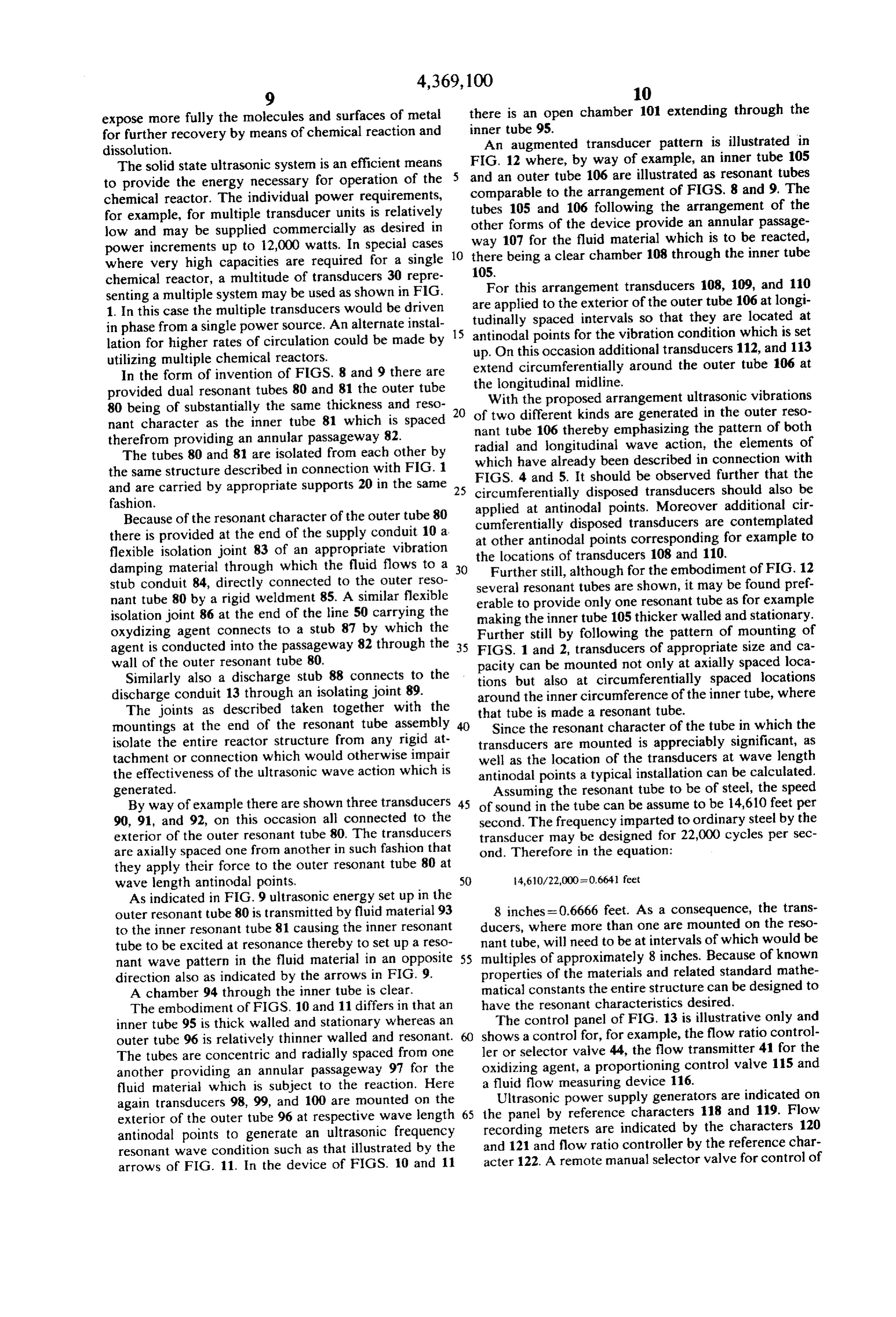
mountings at the end of the resonant tube assembly Since the resonant character of the tube in which the isolate the entire reactor structure from any rigid at transducers are mounted is appreciably significant, as tachment or connection which would otherwise impair well as the location of the transducers at wave length the effectiveness of the ultrasonic wave action which is antinodal points a typical installation can be calculated. generated. Assuming the resonant tube to be of steel, the speed By way of example there are shown three transducers 45 of sound in the tube can be assume to be 14,610 feet per 90, 91, and 92, on this occasion all connected to the second. The frequency imparted to ordinary steel by the exterior of the outer resonant tube 80. The transducers transducer may be designed for 22,000 cycles per sec are axially spaced one from another in such fashion that ond. Therefore in the equation:
they apply their force to the outer resonant tube 80 at wave length antinodal points. 50 14,610/22,000 =0.664 feet As indicated in FIG. 9 ultrasonic energy set up in the outer resonant tube 80 is transmitted by fluid material 93 8 inches = 0.6666 feet. As a consequence, the trans to the inner resonant tube 81 causing the inner resonant ducers, where more than one are mounted on the reso tube to be excited at resonance thereby to set up a reso nant tube, will need to be at intervals of which would be nant wave pattern in the fluid material in an opposite 55 multiples of approximately 8 inches. Because of known direction also as indicated by the arrows in FIG. 9. properties of the materials and related standard mathe A chamber 94 through the inner tube is clear. matical constants the entire structure can be designed to The embodiment of FIGS. 10 and 11 differs in that an have the resonant characteristics desired. inner tube 95 is thick walled and stationary whereas an The control panel of FIG. 13 is illustrative only and outer tube 96 is relatively thinner walled and resonant. shows a control for, for example, the flow ratio control The tubes are concentric and radially spaced from one ler or selector valve 44, the flow transmitter 41 for the another providing an annular passageway 97 for the oxidizing agent, a proportioning control valve 115 and fluid material which is subject to the reaction. Here a fluid flow measuring device 116.
again transducers 98, 99, and 100 are mounted on the Ultrasonic power supply generators are indicated on exterior of the outer tube 96 at respective wave length 65 the panel by reference characters 118 and 119. Flow antinodal points to generate an ultrasonic frequency recording meters are indicated by the characters 120 resonant wave condition such as that illustrated by the and 121 and flow ratio controller by the reference char acter 122. A remote manual selector valve for control of arrows of FIG. 11. In the device of FIGS. 10 and 11
Page 11
the total flow leaving the reactor is shown at 123 and a 15 to 30 minutes has been found sufficient to soften the manual automatic flow ratio selector valve at 124. Be tar or the crushed tar sand before final extraction takes cause of the nature of the apparatus and process made place in the chemical reactor 150.
possible by the arrangement of equipment shown, care The pre-mixed slurry enters the annular high fre ful control and regulation is a requisite and for adequate quency energy chamber of the chemical reactor 150 effectiveness all controls and indicators need to be con where cavitation quickly reduces the tar sand by implo centrated at a single location. sions to individual grains. As the action continues, cavi Although the application of the chemical reactor for tation also blends the solvent with the bitumen and the the mine processing industry has been detailed in this energy implosions separate it from the sand. The unique disclosure, there are other significant uses for the chem 10 advantage of using sonic energy is that it acts on each ical reactor in the chemical processing industry gener individual grain of sand. Cavitation, the minute vacuous ally where such methods and technology may be uti bubbles that constantly form and collapse, causes an lized in other forms of processing namely, dispersion, intense cleaning, chemical washing, mechanical agitation, mix ing the softened bitumen to be pulled away fromcaus energy release that implodes the material, ing and completion of chemical reactions by the intro 15 hard surface of the sand much the same as it pulls soilthe or duction of various forms of oxidizing agents in a con contamination away from hard surfaces in cleaning trolled manner.
An example of a system capable of accommodating, to operations. In this instance, however, the purpose is not clean the sand, but to remove the bitumen.
for example, a method or process directed to solvent The next step in the process is to pass the slurry mix extraction of oil from tar sands or oil sands is shown in 20 a pilot extraction plant system as illustrated in FIG. 14. ture of bitumen, sand and solvent by gravity flow As there shown, the system is one set up for operation through a line 153 to a clarifier 154. principally as a gravity system in the interest of econo idsThe clarifier provides a standard means for liquid-sol separation. The solid in this case is sand and the mizing further power requirements. liquid represents the oil-solvent solution. Water within An acceptable apparatus as shown would involve 25 the several processing steps. The first step in the process is cificclarifier gravity acts as a separation medium since the spe of the oil-solvent is considerably lower the reduction of the oil sand agglomerate. Deagglomer than water. The oil-solvent mixture rises to the top of ation to a maximum one-quarter inch size is sufficient, since the high frequency energy action quickly reduces the water solution and is skimmed off the top through a line 160 for further processing. The clarifier mechanism the tar sand to individual granules. The tar sands would 30 also be processed continuously by a single-toothed crusher whichprovides a high rate of circulation and agitation causes further dissolution of the bitumen in the since the material is easily reduced. The tar sands thus solvent solution. The clean and slowly falls to the bot supplied by the mass 130 are continuously fed to a tom of the clarifier and is removed through a line 156 by hopper 132. a screw auger. A slight amount of detergent added to The material is then funnelled into an automatic con 35 the water solution will enhance the removal of solvent tinuous weighing gravimetric feeder 133 and weighed from the sand surfaces.
in terms of LBS/HR and from there into a mixing tank Waste water from the clarifier is removed through a 134 which has an impeller agitator 135. In this instance line 157 and processed in a water filtration unit 158, solvent 136 from a solvent tank 137 is fed by gravity to clean water being removed through a line 159 and re the mixing tank 134. The flow is metered by a meter 138 turned to the clarifier. Make-up water is supplied to the in terms of LBS/HR in a solvent line 139. The flow through a line 140 is manually set to a metered amount constant water level inline clarifier by means of 152 in order to maintain a the clarifier 154.
on a weight basis by means of a manual valve 143 so that The next step in the process is to pass the oil-solvent the solvent flow weight to the mixing tank 134 and the solution to a fractionating tower 163 by means of a line tar sand flow weight to the tank 134 are at a ratio of one 45 160 and pump 162 as metered by a meter 161. The sol to one, or less, by weight. A heater 144 in the solvent vent is taken off, tank 137 maintains a low temperature of 23° C. A float tank 137 by meansdecanted and returned to the solvent control mechanism in tank 134 will automatically close at approximately 18 API is 165 of a line for further use. The oil a normally open valve 142 by means of a pneumatic line and subjected to the usual processes, through
such as cracking, 141 when the tank level of 134 exceeds its desired level SO reforming and alkylation, to produce motor fuel, fuel oil for safety purposes. A solvent 136 suitable for the pro and similar products. Solvent loss experimentally is less cess is No. 2 oil.
than 1%. Oil extraction from tar sands has been shown
From the tank 134 the shurry mixture flows continu ously through a discharge line 146 in which there is a experimentally
The
continuous flow solvent extraction process, as hand-operated valve 147 and a metering device 148 to 55 shown in the schematic the upper end of a chemical reactor assembly 150 of the 14, may be implementedpilot plant illustrated in FIG. to a large oil extraction pro type heretofore made reference to. duction plant of 10,000 Bbls/day to 20,000 Bbls/day or A by-pass line 170 is provided to pass a small amount higher of fresh solvent 136 as a chemical reagent to the chemi practice.and within the framework of sound engineering cal reactor assembly and is metered by a meter 171 through a valve 172. This relatively small by-pass chem theThis, for example, may be accomplished by enlarging outside diameter of the chemical reactor 150 to six ical reagent flow provides a process corrective means to feet or larger whereby the annular processing chamber produce highest extraction efficiency within the chemi is designed to desired volumetric considerations while cal reactor.
at the same time maintaining the proper and most effi
The mixing tank 134 also serves a significant function 65 cient as a detention device since the tank volume is designed chamber energy transmission distance within the annular to be many times the annular processing chamber vol for efficient extraction purposes. ume of the chemical reactor. A flow detention time of Individual high capacity chemical reactor units may be added in the form of modules to obtain any total
Page 12
desired plant capacity. These modules would operate in able in various grades from 85 percent to 95 percent a parallel configuration and be supplied by one or sev NaCN.
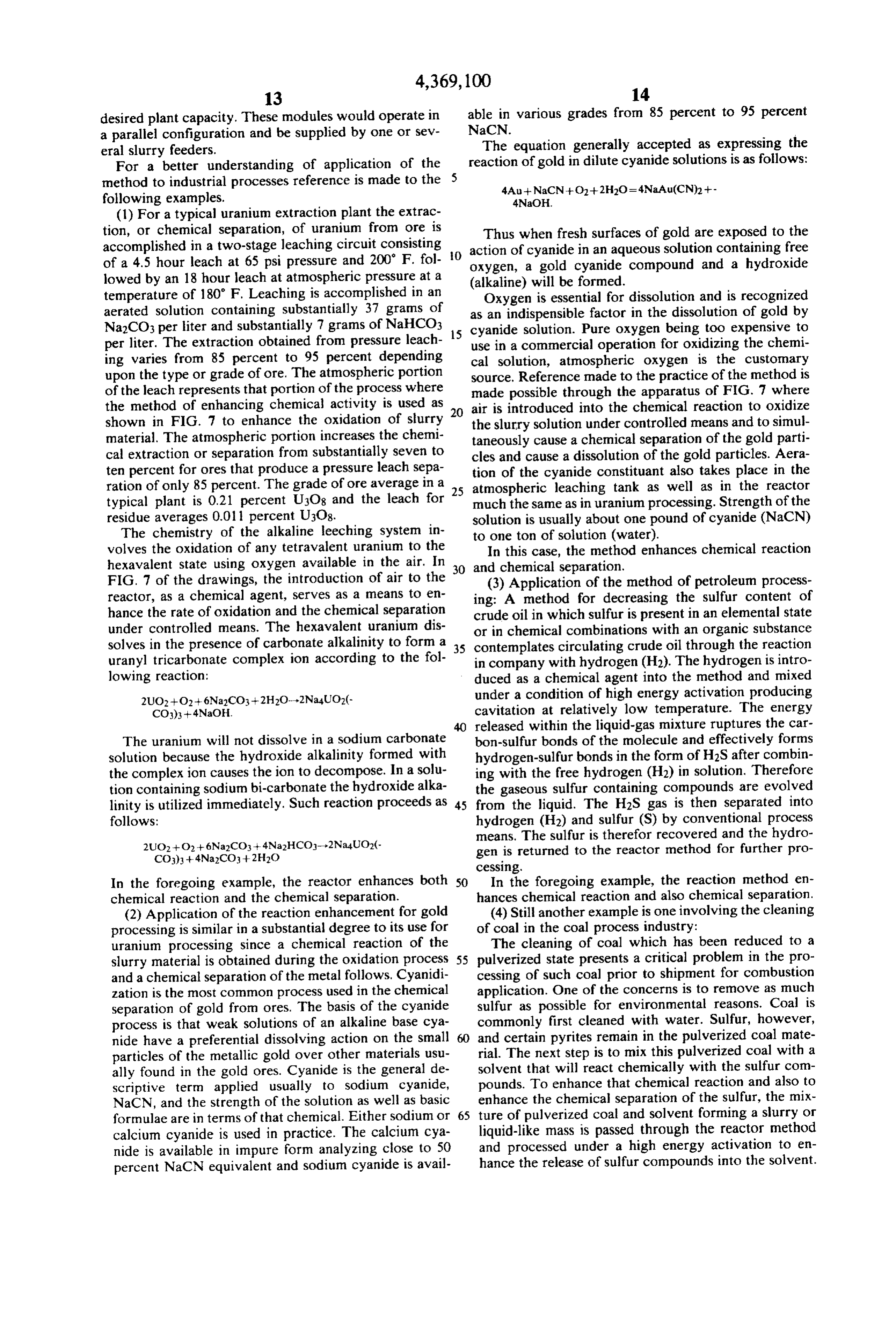
eral slurry feeders. The equation generally accepted as expressing the For a better understanding of application of the reaction of gold in dilute cyanide solutions is as follows: method to industrial processes reference is made to the 5 following examples.
(1) For a typical uranium extraction plant the extrac tion, or chemical separation, of uranium from ore is Thus when fresh surfaces of gold are exposed to the accomplished in a two-stage leaching circuit consisting action of cyanide in an aqueous solution containing free of a 4.5 hour leach at 65 psi pressure and 200' F. fol- 0 oxygen, a gold cyanide compound and a hydroxide lowed by an 18 hour leach at atmospheric pressure at a (alkaline) will be formed.
temperature of 180° F. Leaching is accomplished in an Oxygen is essential for dissolution and is recognized aerated solution containing substantially 37 grams of as an indispensible factor in the dissolution of gold by Na2CO3 per liter and substantially 7 grams of NaHCO3 15 cyanide solution. Pure oxygen being too expensive to per liter. The extraction obtained from pressure leach use in a commercial operation for oxidizing the chemi ing varies from 85 percent to 95 percent depending cal solution, atmospheric oxygen is the customary upon the type or grade of ore. The atmospheric portion source. Reference made to the practice of the method is of the leach represents that portion of the process where made possible through the apparatus of FIG. 7 where the method of enhancing chemical activity is used as air is introduced into the chemical reaction to oxidize shown in FIG. 7 to enhance the oxidation of slurry 20 the slurry solution under controlled means and to simul material. The atmospheric portion increases the chemi taneously cause a chemical separation of the gold parti cal extraction or separation from substantially seven to cles and cause a dissolution of the gold particles. Aera ten percent for ores that produce a pressure leach sepa tion of the cyanide constituant also takes place in the ration of only 85 percent. The grade of ore average in a 25 atmospheric leaching tank as well as in the reactor typical plant is 0.21 percent U3O8 and the leach for much the same as in uranium processing. Strength of the residue averages 0.011 percent U3O8. solution is usually about one pound of cyanide (NaCN) The chemistry of the alkaline leeching system in to one ton of solution (water).
volves the oxidation of any tetravalent uranium to the In this case, the method enhances chemical reaction hexavalent state using oxygen available in the air. In 30 and chemical separation.
FIG. 7 of the drawings, the introduction of air to the (3) Application of the method of petroleum process reactor, as a chemical agent, serves as a means to en ing: A method for decreasing the sulfur content of hance the rate of oxidation and the chemical separation crude oil in which sulfur is present in an elemental state under controlled means. The hexavalent uranium dis or in chemical combinations with an organic substance solves in the presence of carbonate alkalinity to form a 35 contemplates circulating crude oil through the reaction uranyl tricarbonate complex ion according to the fol in company with hydrogen (H2). The hydrogen is intro lowing reaction: duced as a chemical agent into the method and mixed under a condition of high energy activation producing cavitation at relatively low temperature. The energy released within the liquid-gas mixture ruptures the car
The uranium will not dissolve in a sodium carbonate bon-sulfur bonds of the molecule and effectively forms solution because the hydroxide alkalinity formed with hydrogen-sulfur bonds in the form of H2S after combin the complex ion causes the ion to decompose. In a solu ing with the free hydrogen (H2) in solution. Therefore tion containing sodium bi-carbonate the hydroxide alka the gaseous sulfur containing compounds are evolved linity is utilized immediately. Such reaction proceeds as 45 from the liquid. The H2S gas is then separated into follows: hydrogen (H2) and sulfur (S) by conventional process means. The sulfur is therefor recovered and the hydro gen is returned to the reactor method for further pro cessing.
In the foregoing example, the reactor enhances both 50 In the foregoing example, the reaction method en chemical reaction and the chemical separation. hances chemical reaction and also chemical separation. (2) Application of the reaction enhancement for gold (4) Still another example is one involving the cleaning processing is similar in a substantial degree to its use for of coal in the coal process industry: uranium processing since a chemical reaction of the The cleaning of coal which has been reduced to a slurry material is obtained during the oxidation process 55 pulverized state presents a critical problem in the pro and a chemical separation of the metal follows. Cyanidi cessing of such coal prior to shipment for combustion zation is the most common process used in the chemical application. One of the concerns is to remove as much separation of gold from ores. The basis of the cyanide sulfur as possible for environmental reasons. Coal is process is that weak solutions of an alkaline base cya commonly first cleaned with water. Sulfur, however, nide have a preferential dissolving action on the small 60 and certain pyrites remain in the pulverized coal mate particles of the metallic gold over other materials usu rial. The next step is to mix this pulverized coal with a ally found in the gold ores. Cyanide is the general de solvent that will react chemically with the sulfur com scriptive term applied usually to sodium cyanide, pounds. To enhance that chemical reaction and also to NaCN, and the strength of the solution as well as basic enhance the chemical separation of the sulfur, the mix formulae are in terms of that chemical. Either sodium or 65 ture of pulverized coal and solvent forming a slurry or calcium cyanide is used in practice. The calcium cya liquid-like mass is passed through the reactor method nide is available in impure form analyzing close to 50 and processed under a high energy activation to en percent NaCN equivalent and sodium cyanide is avail hance the release of sulfur compounds into the solvent.
Page 13
Other chemical organic agents acting as catalysts may sources in radially converging directions relative to the also be released into the reactor method to further en composite mass while in said annular passage and trans hance reaction and separation of sulfur. mitting said resonant energy condition to and into said An organic solvent is used and may be selected from composite mass throughout the entire space provided a number of solvents of organic nature which are com by the annular passage, continuing the transmitting of mercially available. In the case under consideration the said energy to all portions of the composite mass as it reactor method enhances chemical reaction and chemi progresses the length of the passage thereby creating a cal separation which takes place during the processing. state of cavitation in the ultrasonic range within the Having described the invention, what is claimed as composite mass for the duration of transit of said com new in support of Letters Patent is as follows: O 1. A method for enhancing chemical activity in a posite mass through said passage, and then collecting continuous system comprising continuously circulating the3.product of said composite mass. A method as in claim 1 including collecting the a predominately liquid mass through the system at a resulting combination of said composite mass in a reser selected rate of flow, continuously introducing a chemi voir, introducing cal agent into the predominately liquid mass to form a 15 reservoir to form a asecondsecond chemical agent into said composite mass, agitating the predominately liquid composite mass, confining the flow of said composite mass to a stream of annular second composite mass while in said reservoir and then cross-sectional shape having an inflow at one end and discharging said second composite mass from the reser an outflow at the other end, moving the composite mass voir.
in a freely flowing stream and at a substantially continu 20 4. A method as in claim 3 including continuously ous rate from said inflow end to said outflow end, set passing a first portion of the second composite mass ting up a multiplicity of ultrasonic sources of resonance from the reservoir to the system and continuously dis throughout the length and circumference of said stream charging a second portion of the second composite mass and transmitting said resonance in radially inwardly from the reservoir while the first portion is being passed converging directions toward and into the free flowing 25 to the system.
stream of said composite mass simultaneously and uni 5. A method as in claim 3 including returning the formly throughout the entire length and perimeter product of said second composite mass to said supply of thereof, whereby to develop a condition of cavitation in the first predominately liquid mass whereby to form a the ultrasonic range while said composite mass is in mixture, and drawing off quantities of said mixture. transit, and then collecting the resulting combination of 30 6. A method as in claim 1 including passing the pre said composite mass at a discharge location. dominately liquid mass through the system by gravity 2. A method of enhancing chemical activity in a con flow, introducing the chemical agent by gravity into the tinuous system comprising preparing a source of supply predominately liquid mass and metering the flow of said of a first predominately liquid mass and placing said first chemical agent in proportion to the flow of said pre predominately liquid mass under a first selected rate of 35 dominately liquid mass to form the composite mass, flow, preparing a source of supply of a second mass passing the composite mass by gravity and in said condi comprising a chemical agent and placing said second tion of cavitation in the ultrasonic range to said dis mass under a second rate of flow, adding the second charge location.
mass to the first predominately liquid mass to form a 7. A method as in claim 6 including adding to the predominately liquid composite mass, confining the predominately liquid mass a mixture of finely divided composite mass to a passage of annular cross-sectional solids and a soluble ingredient and including the step of shape having hard and resilient outer and inner surfaces combining the chemical agent with the soluble ingredi and providing an inlet adjacent one end and an outlet ent, and subjecting the composite mass to said resonant adjacent the other end, injecting said first predomi condition while the combining is taking place, whereby nately liquid mass through said inlet into the passage at 45 the solids are separated from the composite mass, re said first selected rate of flow, introducing said second moving the soluble ingredient with the chemical agent mass into said first predominately liquid mass at a loca in combined condition from the finely divided solids tion upstream of said inlet, thereby forming a free flow and then separating the chemical agent from the soluble ing stream of said composite mass through said passage, material.
constantly sensing the total rate of flow of the compos 50 8. A method as in claim 7 including returning the ite mass in said passage, constantly sensing the rate of chemical agent to the place of introduction after sepa flow of the second mass downstream of said source of rating the chemical agent from the soluble material. supply, bringing both said rates of flow into a counter 9. A method as in claim 6 including making up said balancing relationship whereby to establish a supply composite mass from a finely divided mass of solid flow rate for the second mass in proportion to the total 55 material and water wherein the resulting composite rate of flow of the composite mass, maintaining the flow mass is in the form of a slurry, collecting said slurry in of said second mass into said first predominately liquid a reservoir for introduction of said chemical agent and mass at said supply flow rate, setting up a multiplicity of metering the flow of the chemical agent into the reser ultrasonic sources of resonant energy throughout the voir in proportion to the flow of said composite mass length and circumference of said hard outer surface of 60 the passage, projecting said resonant energy from said with the chemical agentit present
from
said reservoir.
Provenance
- Collection
- Cited prior art
- Original PDF
- patentimages.storage.googleapis.com →
- Filed
- 1981-07-23
- Pages
- 13
- Method
- pdftotext (the PDF's own text layer) + pdftoppm 300dpi page scans
- Source
- Google Patents bibliographic record
- Granted
- 1983-01-18
- Inventors
- Harold T. Sawyer
- Transcribed from
- patentimages.storage.googleapis.com →