patent · US4541910
Method for electroblotting macromolecules from a chromatographic gel
17 September 1985
Page 1 — bibliographic record
United States Patent (19) 11 Patent Number: 4,541,910 Davis, III et al. 45 Date of Patent: Sep. 17, 1985 54 METHOD FOR ELECTROBLOTTING els in Lysates of Escherichia Coli, J. Biol. Chem., vol. MACROMOLECULES FROM A 256, 12836-12839 (1981).
CHROMATOGRAPHC GEL McLellan, T. et al., "Serial Electrophoretic Transfers: A Technique for the Identification of Numerous En (75). Inventors: Fred E. Davis, III, Hamden, Conn.; zymes from Single Polyacrylamid Gels', Biochemical Johathan
Israel
M. Gershoni, Rehovot, Genetics, vol. 19, pp. 647–654 (1981).
Erickson, P. et al., "Quantitative Electrophoretic 73) Assignee: Yale University, New Haven, Conn. Transfer of Polypeptides from SDS Polyacrylamide Gels to Nitrocellulose Sheets: A Method for Their 21 Appl. No.: 549,474 Re-Use in Immunoantoradiographic Detection of Anti 22 Filed: Nov. 7, 1983 gens', J. Immunol. Methods, vol. 51, pp. 241-249 (1982). Gershoni, J. et al., "Electrophoretic Transfer of Prote 51) Int. Cl....................... G01N 27/26; G01N 27/28 ins from Sodium Dodecyl Sulfate-Polyacrylamide Geis 52 U.S. Cl. ................ - 204/1828; 204/299 R to a Positively Charged Membrane Filter", Anal. Bio 58) Field of Search ............ 204/180 G, 180R, 299 R. chem, vol. 124, pp. 396–405 (1982).
Arnheim, N. et al., "Heterogeneity of the Ribosomal
Genes in Mice and Men” Cell, vol. 11, pp. 363-370
3,255,100 6/1966 Raymond ...................... 204/180 G Bolen, J. et al., "Detection and Quantitation of Newcas 3,989,612 11/1976 Kragt et al... ... 204/180 G tle Disease Virus Proteins in Infrared Chicken Embryo 4,049,534 9/1977 Posner .......... ... 204/299 R Cells”, Appl. Environ, Microbiol, vol. 43, pp. 193-199, 4,148,703 4/1979 Trop et al.................... 204/180 G (1982).
Burnette, W., "Western Blotting: Electrophoretic
OTHER PUBLICATIONS Transfer of Proteins from Sodium Dodecyl Sul Stellwag, E. et al., “Electrophoretic Transfer of DNA, fate-Polyacrylamide Gels to Unmodified Nitrocellu lose and Radiographic Detection with Antibody and
RNA and Protein onto Diazobenzyloxymethyl (DBM) Radioiodinated Protein A', Anal. Biochem, vol. 112, Paper', Nucleic Acid Research, vol. 8, pp. 299-317 pp. 195-203 (1981).
(1980). Bittner, Michael et al., “Electrophoretic Transfer of Tas, J. et al., “A Method for the Quantitative Determi Proteins and Nucleic Acids from Slab Gels to Diazo nation of Protein Incorporated in Solubilizable Poly benzyloxymethyl Cellulose or Nitrocellulose Sheets', acrylamide Gels', Anal. Biochem., vol. 100, pp. 264-270 Analytical Biochemistry, 102 (1980), pp. 459-471. (1982). Primary Examiner-Andrew H. Metz Towbin, H. et al., "Electrophoretic Transfer of Proteins Assistant Examiner-B. J. Boggs, Jr. from Polyacrylamide Gels to Nitrocellulose Sheets: Attorney, Agent, or Firm-Walter J. McMurray Procedure and some Applications', Proc. Nat. Acad.
Sci. U.S.A., vol. 76, pp. 4350-4354 (1979). 57 ABSTRACT Biorad Laboratories, Manufactures Literature, Jan. An improved method of electroblotting macromole 1982. cules from a chromatographic gel is claimed. The Gershoni, J. et al., "Protein Blotting: Principles and method comprises a design for wire electrode arrays Applications', Anal. Biochem., vol. 131, pp. 1-15 (1983). that are capable of generating either highly uniform or Gibson, W., “Protease-Facilitated Transfer of High controlled predetermined gradient electric fields. A -Molecular-Weight Proteins during Electrotransfer to gradient electric field is particularly suited for the quan Nitrocellulose', Anal. Biochem, vol. 118, pp. 1-3 titative electroblotting of proteins with a wide range of (1981). molecular weights.
Howe, J. et al., “A Sensitive Immunoblotting Method for Measuring Protein Synthesis Initiation Factor Lev 4 Claims, 18 Drawing Figures
Page 2
Drawing sheet — no readable text.
Page 3
Drawing sheet — no readable text.
Page 4
Drawing sheet — no readable text.
Page 5
Drawing sheet — no readable text.
Page 6
Drawing sheet — no readable text.
Page 7
Drawing sheet — no readable text.
Page 8
Drawing sheet — no readable text.
Page 9
Drawing sheet — no readable text.
Page 10
retograms to immobilizing matrices one may benefit
METHOD FOR ELECTROBLOTTING from the following advantages: (1) wet filters are pliable MACROMOLECULES FROM A and easy to handle; (2) the immobilized proteins are CHROMATOGRAPHIC GEL readily and equally accessible to various ligands (since the limitations introduced in gels by differential poros
BACKGROUND OF THE INVENTION ity are obviated); (3) transfer analysis generally calls for 1. Field of the Invention small amounts of reagents; (4) processing times (incuba This invention relates to macromolecule blotting and tions and washings) are significantly reduced; (5) multi more particularly to an improved method for electro 10 ple replicas of the gels may be made; (6) transferred eluting and blotting macromolecules from a chromato patterns may be stored for months prior to their use; (7) graphic gel to an immobilizing matrix. protein transfers may undergo multiple analyses. More 2. Prior Art over, the transferred protein patterns are amenable to Smithies, Biochem. J. 61: 629-641 (1955), showed analyses which would be otherwise extremely difficult that starch gel could serve as a molecular sieve through 15 or impossible to perform on gels. which zone electrophoresis of proteins occurs. Since The term "blotting' today refers to the process of then, there have been constant innovations in the tech transferring biological macromolecules such as nucleic nique of gel electrophoresis. The introduction of acryl acids and proteins from gels to an immobilizing matrix. amide gels, discontinuous buffer systems, the use of The term is often used in conjunction with the relevant sodium dodecyl sulfate (SDS) to disaggregate protein macromolecule, e.g., protein blotting, DNA blotting complexes to be resolved on gels, and the eventual 20 and RNA blotting. The resulting filter containing trans combined use of SDS in discontinuous buffer systems ferred immobilized macromolecule is known as a "blot' for polyacrylamide gel electrophoresis have been major or "transfer” and can be incubated with a ligand, a contributions to the development of one of the most procedure which may be referred to as "overlay'. widely used analytical and preparative tools of modern Thus, for example, immuno-overlay, lectin overlay or
calmodulin overlay refers to the incubation of a blot
The main object of these techniques has been to visu with an antibody, lectin or calmodulin, respectively. ally demonstrate the homogeneity or complexity of a In general, protein blotting should be viewed as two protein preparation by following the appearance of sequential disappearance of a particular "band' throughout a from the gelevents, and namely the elution of the polypeptide the adsorption of the eluted material to given experimental procedure. One-dimensional gels 30 immobilizing matrix.
were found to be adequate, provided only relatively anThree main driving forces have been exploited for simple protein samples such as viruses, bacteriophages, macromolecule elution. One is diffusion. Here, the gel erythocyte ghost membranes, etc., were being analyzed. containing the macromolecules to be transferred is More complex systems demanded greater resolving sandwiched between two sheets of immobilizing matrix power and new two-dimensional gel systems were de 35 which are in turn sandwiched veloped. Today, even the thousands of polypeptides stainless steel screens. This finalbetween foam pads and assembly is then sub which are a part of the more intricate proteinaceous samples can be efficiently resolved. merged in two liters of buffer and allowed to sit for The task of unequivocally correlating a "band' or 36-48 hours. The result of this incubation is that two "spot” with a recognized function has often been diffi 40 identical not be an replica blots are obtained. This may or may advantage. This depends on the quantity of cult, and this is even more so when the resolution of the proteins depends on their denaturation. Nevertheless, macromolecule present and the sensitivity of the assay many approaches have been developed which allow the to be used. The efficiency of transfer may reach 75% identification of a specific enzyme, antigen, glycopro with half the quantity available for each matrix. Since tein or hormone receptor, etc., in a gel. These tech 45 diffusion should occur in all directions loss of resolution niques rely on the ability to maintain at least one of the might be expected. Because all the macromolecules in following prerequisites: (1) that the polypeptides retain the gel are subject to the same diffusive force there is a their activity throughout electrophoresis; (2) renatur bias in the speed of elution in favor of the lower molecu ation of a denatured polypeptide; and (3) covalent lar weight macromolecules.
crosslinkage of the protein in question to a detectable 50 This speed bias is a disadvantage especially when the ligand prior to electrophoresis. Moreover, the actual purpose of the technique is to quantify the amount of processing of the gels entails multiple manipulations and each component in a particular sample or in comparing extensive incubations and washing procedures. This is samples. The speed bias is also a disadvantage when very time consuming and quite often prone to handling subdetectable amounts of the higher molecular weight accidents such as breakage and tearing of wet gels or 55 macromolecules are eluted.
cracking during the drying of the gels. The second means of macromolecule blotting is based In attempting to overcome some of the problems on mass flow of buffer (convection) through the gel. encountered in analyzing gels, a new approach has This is the traditional procedure described by Southern, evolved. A number of reports have been published J. Mol. Biol. 98: 503–517 (1975). The gel is placed in a demonstrating that the well established approach of 60 reservoir of buffer. A membrane filter is applied to the "Southern-blotting', i.e., transferring DNA patterns gel and paper towels are piled onto the membrane filter. from agarose gels to nitrocellulose membrane filters, The towels absorb the buffer from the reservoir can be applied to protein patterns in polyacrylamide through the gel and membrane filter. This movement of gels. Intact protein patterns are eluted from the gels and fluid serves as the driving force which elutes the prote are immobilized on a filter substratum. The substratum 65 ins out of the gel which are then trapped in the mem is, in turn, subjected to the same type of procedures brane filter to create the blot. The advantages of this which have been used on gels for "band' or "spot' technique are that it takes less time (2-12 hrs) than identification. However, by transferring electropho diffusion blotting, is more efficient, and is inexpensive
Page 11
since a reservoir is the only apparatus required. The (1981) have been reported. However, operating units major disadvantage is that this method of elution is only with these electrode designs require high current, e.g., practical with agarose gels and is less suitable for use 1.5A for two hours for the graphite slabs. with polyacrylamide gels. A modification of this ap Bittner reports an apparatus employing 12 mill plati proach has been suggested which allows bidirectional 5 num wire for electrodes and cites indirect experimental blotting, i.e., blotting with two membrane filters, one on evidence to conclude a homogeneous field is produced. either side of the gel. The time for efficient solution has The electrode is formed by stringing uninsulated plati been dramatically reduced by applying a vacuum to num wire vertically 19 cm, horizontally 5.5 cm, again facilitate the process-Peferoen, et.al., FEBS Lett. 145: vertically for 19 cm, again horizontally for 5.5 cm and 369-372 (1982). 10 finally vertically for 19 cm. The distance of the two The most widely used mode for protein blotting (it is outer vertical portions of the platinum wire from the quite often found to be advantageous in nucleic acid plexiglass walls of the apparatus are 2.4 cm. While it is blotting as well) is based on electroeluting the macro not stated it appears from a diagram of the apparatus molecule from the gel. The concept of electroelution of that the vertical portions of the wire forming the anode macromolecules for blotting was originally described 15 and cathode are aligned. The electrode assemblies are by Arnheim and Southern, Cell 11: 363-370 (1977). positioned very close (1.5 cm) to the gel. To infer that Subsequently, numerous apparatus designs have been the electric field produced by this electrode design is reported and some are commercially available. The uniform over the entire surface of the chromatographic essence of the technique is as follows. A wet filter mate gel, Bittner, et.al., compared the separation patterns of rial is placed on a gel making sure that no air bubbles are 20 nucleic acids on 0.75% agarose gels with the separation caught within the filter or between the filter and the gel. pattern after transfer to the matrix and observed that the The filter and gel are then sandwiched between sup electroelution had occurred without distortion and with portive porous pads such as "Scotch Brite' scouring little loss of resolution. However, since nucleic acid pads, foam rubber or layers of wet blotting paper. The transfers from agarose gels is readily accomplished by assembly is then supported by solid grids (usually non- 25 the technique of Southern blotting the validity of this conductive). It is very important that the gel and filter test to conclude that a uniform electric field is generated are firmly held together. This ensures good transfer and by this electrode design is questionable. Even though prevents distortion of the protein bands. The supported the transferred patterns covered only 30% of the slab 'gel-filter sandwich' is inserted into a tank containing surface area they extrapolated their observation to the "transfer buffer' and placed between two electrodes. 30 entire gel surface and concluded that the electrical field The electrodes are connected to a power supply. Typi was uniform over the entire gel surface. Since electrode cal currents employed are in the range of 250 mA. An designs will produce uniform but different electric economical, yet efficient, design that seems to work fields in different areas of a gel, the validity of extrapo reasonably well is that described by Bittner, et.al., Anal. lating the observations from one area of a gel to the Biochem. 102: 459-471 (1980). 35 entire gel is questionable. Additionally, the fact that The advantage of electroelution of macromolecules is some loss of resolution does occur upon transfer further that the time needed for elution is greatly reduced. weakens inferences of a unifrom electric field. Additionally, since the electric field strength used for The efficiency of the transfer of the individual macro elution is readily quantifiable and manipulable, the tech molecular elements from the gel to the immobilizing nique is conducive to the determination of exact and 40 matrix seems to depend on the chemical nature of the readily reproducible optimum transfer conditions. element, i.e., whether it is protein or nucleic acid, the Several apparatus have been reported which utilized composition of the gel and the molecular weight of the different designs and construction for the electrodes. individual elements. Many researchers have reported The design and construction of the electrode system is that smaller molecular weight fragments from the elec important because of the need as pointed out by Bittner, 45 trophoretic separation of protein isolates on polyacryl et.al., for a uniform electric potential, i.e., a homogene amide gels are eluted with greater efficiency than larger ous field across the entire surface of a chromatographic fragments. See for example: Burnette, Anal. Biochem. gel. A homogeneous field is needed to ensure that the 112: 195-203 (1981), Gershoni and Palade, Anal. Bio macromolecules in the different lanes of the gel are chem. 124: 396-405 (1982), Howe and Hershey, J. Biol. uniformly transferred to the immobilizing matrix. Only 50 Chem. 256 12836-12839 (1981), McLellan and Ram then can lane to lane comparisons be made. The ideal shaw, Biochem. Genet. 19: 647–654 (1981). This effect way of designing an apparatus which would exert a was documented particularly well by Howe and Her homogeneous field on a chromatographic gel would be shey. By changing the immobilizing matrix every hour to use two parallel metal electrode plates. Because the they were able to show that in two hours the low metal electrodes would have little resistance in compar-55 molecular weight polypeptides were efficiently eluted ison to the buffer solution any potential applied to the whereas six hours were necessary to elute sufficient electrodes would be uniformly distributed across their amounts of high molecular weight polypeptides. To entire surface, thus providing a uniform electric field illustrate contradiction in the state of the art, Bittner with which to elute the macromolecules from the slab claims that proteins with a molecular weight range of gel. A platinum electrode is preferred because platinum 60 14,000 to 110,000 were eluted and transferred virtually is not readily degraded by electrolysis. The use of plati quantitatively from a SDS polyacrylamide gel. Towbin, num foil for electrodes is impractical because of its high et.al., (Proc. Nat. Acad. Sci. U.S.A. 76, 4350-4354 cost. Apparatus employing a stainless steel cathode (1979) reports quantitative transfers in urea but not in plate with a platinum wire anode (Stellwag and Dahl SDS polyacrylamide gels.
berg, Nucleic Acid Research 8:299-317 (1980), McLel- 65 A number of suggestions have been made to over lan and Ramshaw, Biochemical Genetics 19: 647-654 come or mitigate this molecular weight bias in a trans (1981) and two graphite slabs weighing 3.75 lbs. each as fer, among them (i) the use of reversible gel crosslinkers anode and cathode, Gibson, Anal. Biochem. 118: 1-2 (Tas, et.al., Anal. Biochem. 100: 264-270 (1979) (instead
Page 12
of bisacrylamide), followed by gel depolymerization previous object, provides the user with a level of con prior to transfer (Bolen, et.al., Appl. Environ. Mi trol and function previously unavailable. crobiol. 43: 193-199 (1982), Renart, et.al., Proc. Nat. Another object of this invention is to provide a tool Acad. Sci. U.S.A. 76: 3116-3120 (1979); (ii) limited by which the user is capable of measuring the relative protease digestion of high molecular weight proteins field strength and its distribution within any apparatus. during electrophoretic transfer to convert them to This provides the user with the ability to evaluate and smaller more easily elutable peptides (Gibson, Anal. monitor the fields generated by various electrode ar Biochem. 118: 1-3 (1981)); (iii) addition of detergent rays. . . . . SDS to "transfer buffer" to facilitate elution of high These and other objects of the invention are achieved molecular weight proteins (Erickson, et.al., J. Immunol. O by using an electric field which is uniform over the Methods 51: 241-249 (1982). The effect of acrylamide entire length of a chromatographic gel or an electric concentration on protein elution has not been studied. field which varies in a predetermined and controlled One would expect that the elution of high molecular way over the length of a chromatographic gel. The weight peptides would be affected by the porosity of invention consists of multiple pairs of aligned electrodes the gel matrix (Gershoni and Palade, Anal. Biochem. 5 of opposite charge, each pair accurately spaced from its 131: 1-15 (1983). adjacent pair of aligned electrodes. The end pairs of
OBJECT AND SUMMARY OF THE INVENTION
aligned electrodes must be accurately spaced from the nonconducting surfaces of the electroelution chamber.
To facilitate the description of the objects and the Each aligned electrode pair is connected through a description of the invention, the following terms are 20 device capable of varying the applied electric potential. described with respect to the longest sides (top to bot By varying the electric potential of each electrode pair tom) of the nonconductive box in which the electroblot the electric field along the length of the chromato ting is performed: graphic gel can be uniformly varied. The chromato (1) the frontal plane is the vertical plane which runs graphic gel should be mounted midway between the from top to bottom and left to right of the box; 25 aligned pairs of electrodes with equal but opposite (2) the saggital plane is the vertical plane which runs charge. To monitor the applied electric potential, a from top to bottom and front to back of the box; and voltmeter whose input can be switched to any selected (3) the transverse plane is the horizontal plane which electrode pair is used to measure the applied field inten runs left to right and front to back of the box. sity.
The samples to be separated by electrophoresis are 30 BRIEF DESCRIPTION OF THE DRAWINGS placed at discreet positions at one end of the gel. The gel is placed in an electric field so that the samples The invention will be described with reference to the migrate from the top to the bottom. Each sample de accompanying drawings, which form a part of this spec fines a lane down which its components travel and are ification, and wherein:
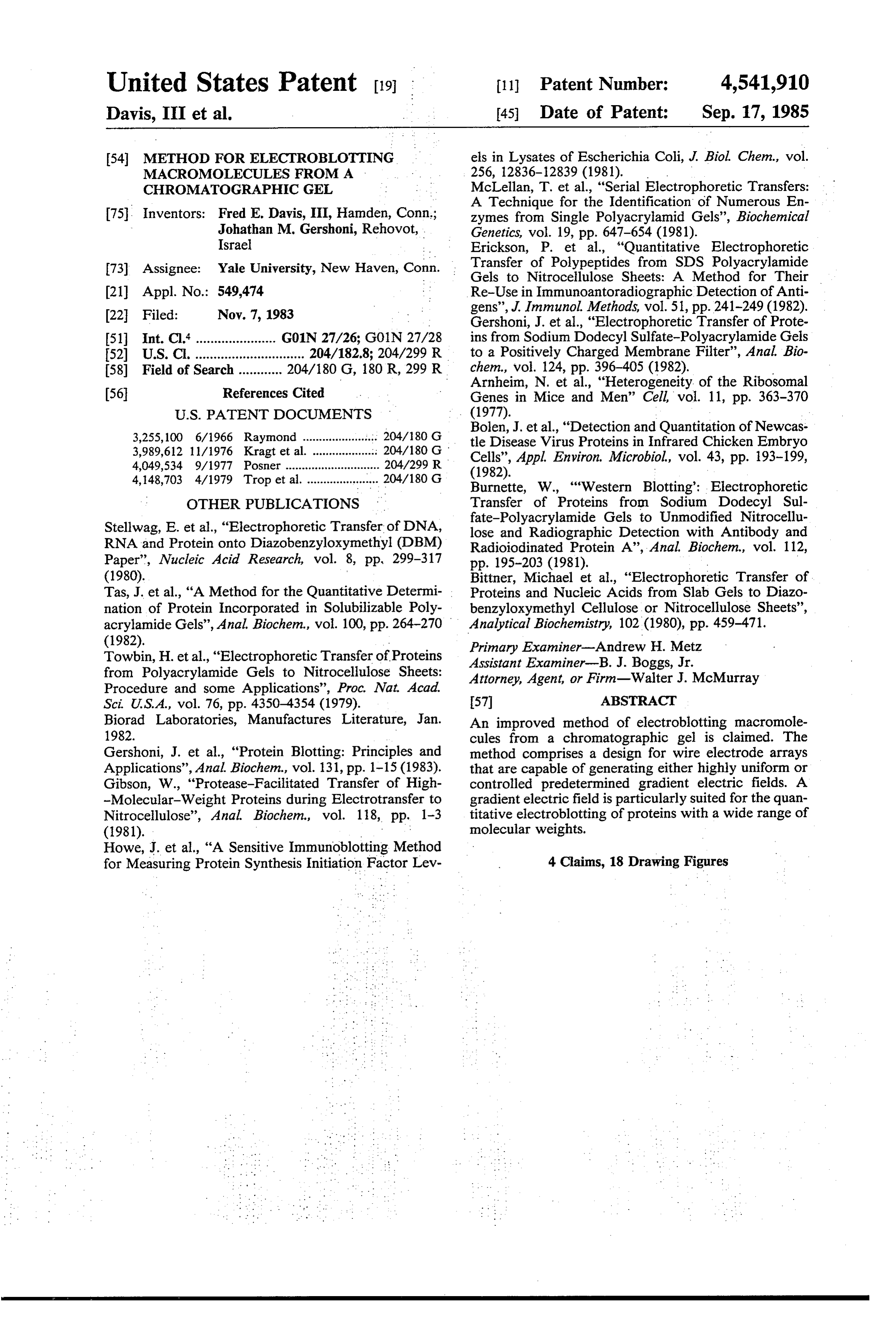
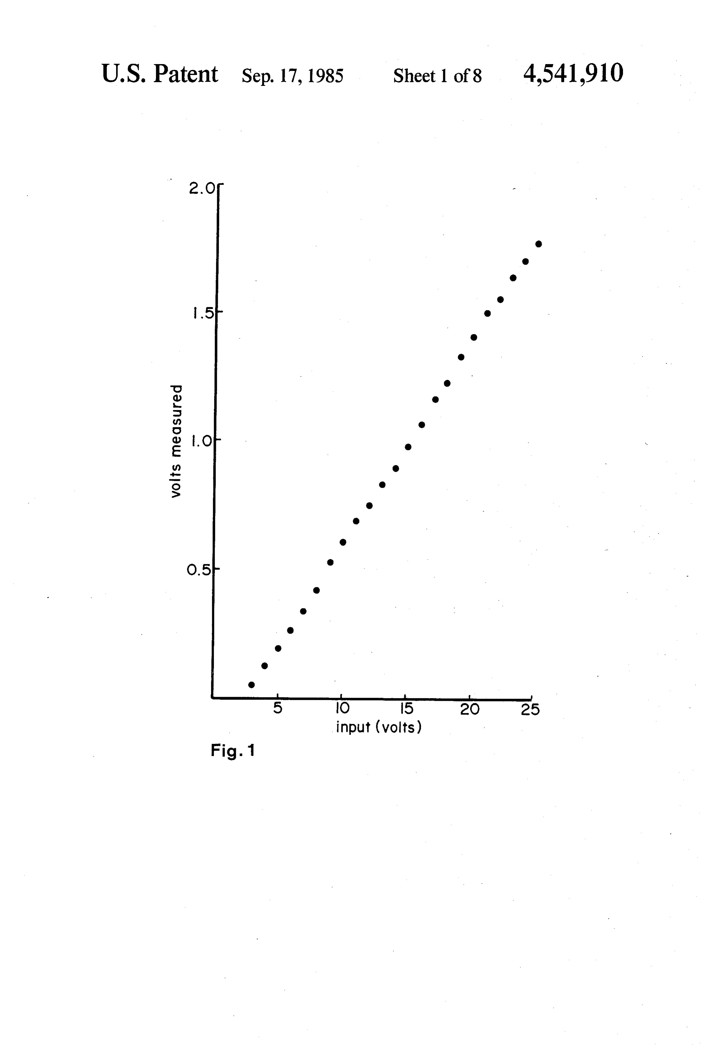
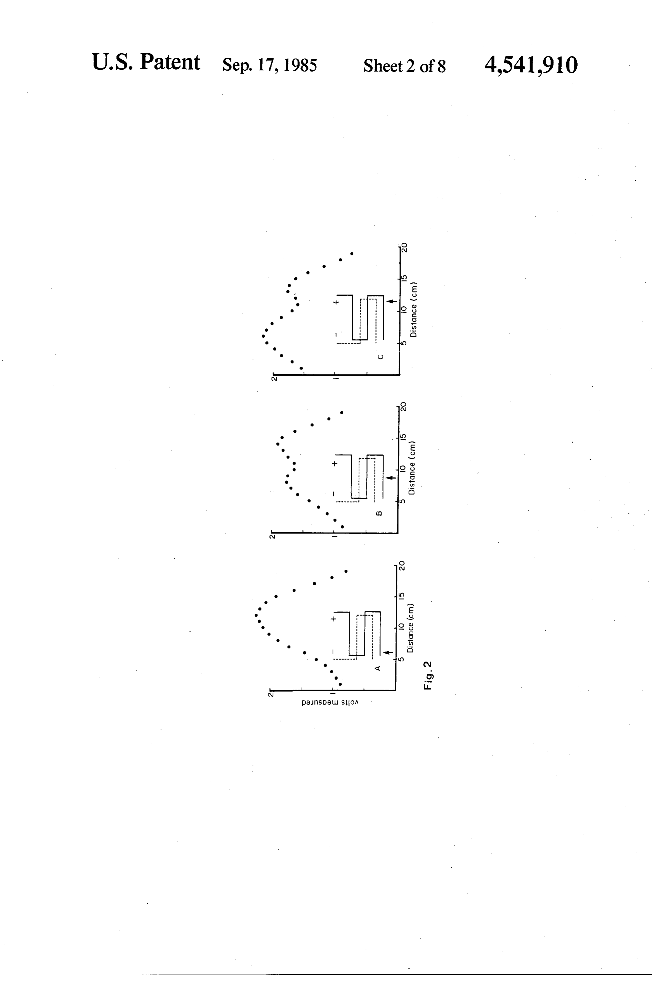
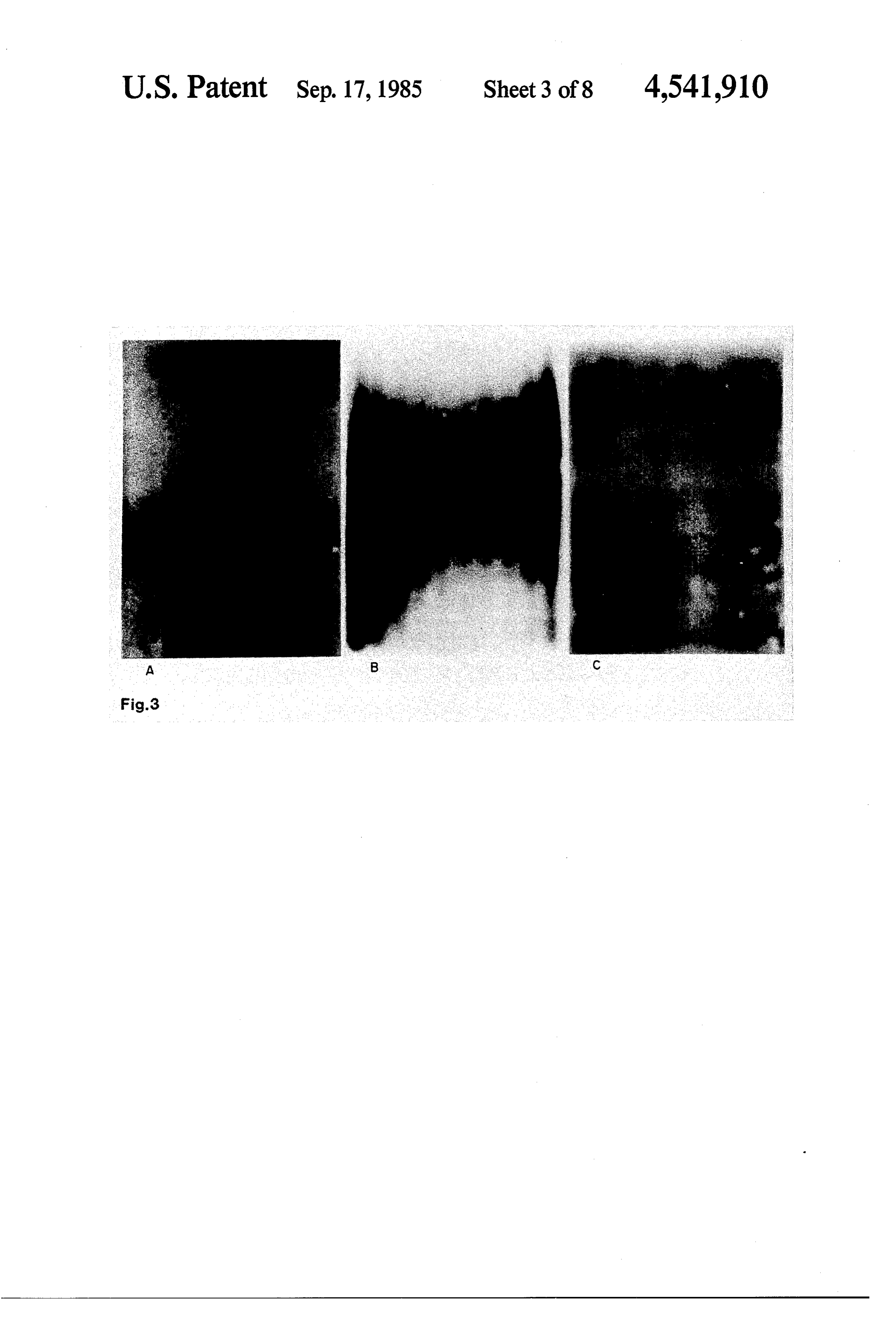
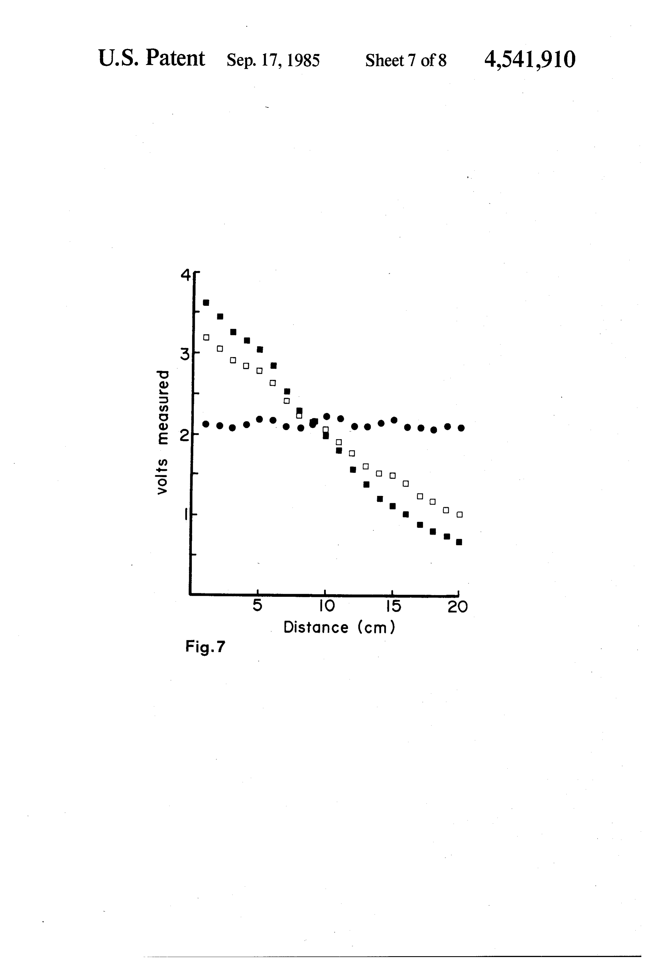
separated, after which the gel is placed in a second 35 FIG. 1 is a plot showing the change in the electric electric field, perpendicular to its surface, for the pur field as a function of input voltage to the electrode pose of blotting.. . array;
It is an object of this invention to provide an im FIG. 2 is a graphical demonstration of the extensive proved method for producing uniform electric fields for variation in the electric field intensity measured in a blotting which is both economic and efficient i.e., re 40 commercially available apparatus; quires minimal currents to electroelute the macromole FIG. 3 shows autoradiograms of a series of transfers cules from the chromatographic gels, e.g., polyacryl from gels containing uniform suspensions of a radioac amide. tive macromolecule;
It is another object of this invention to provide a FIG. 4 shows computer simulations of asymmetric method for producing an electric field which is uniform 45 electrode arrays;
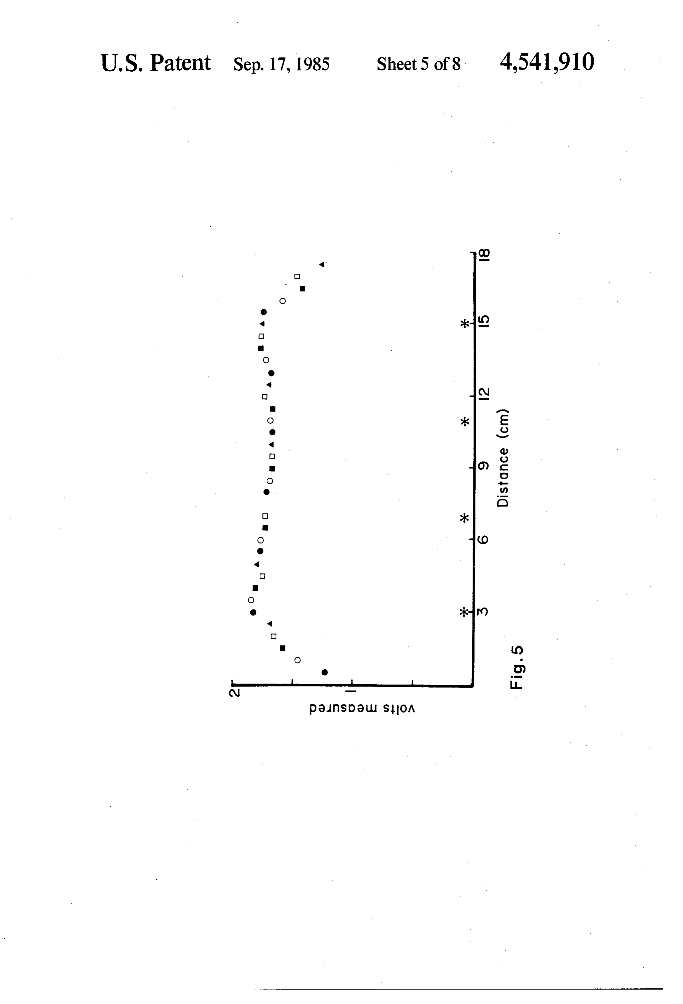
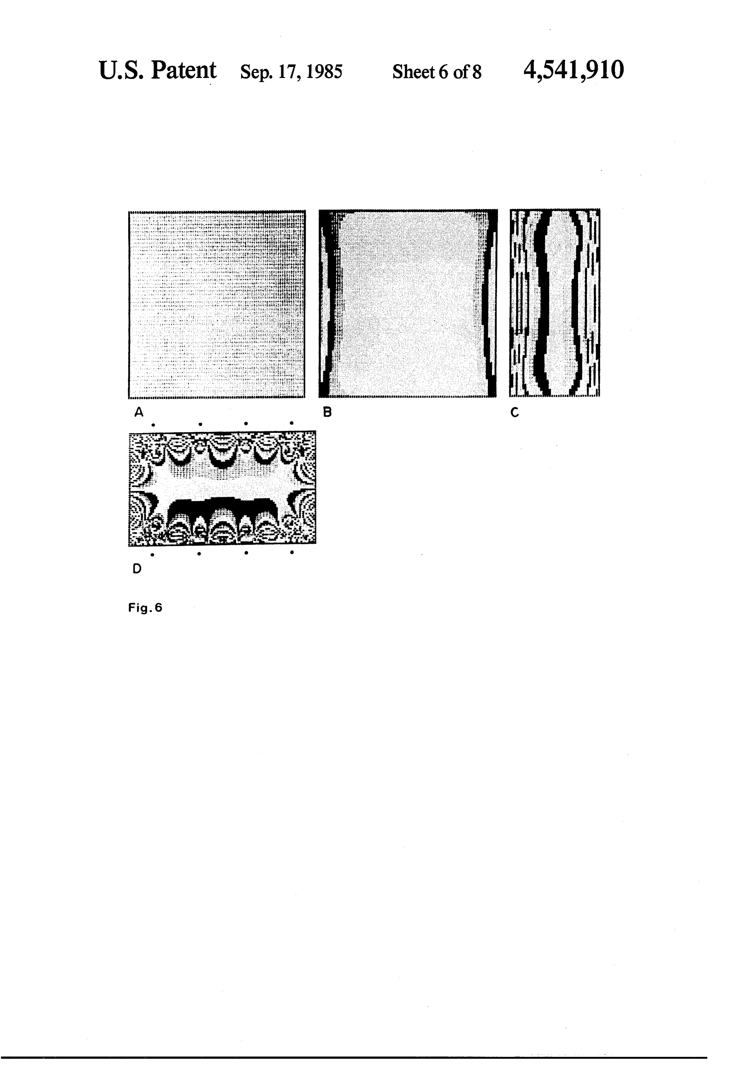
at each transverse plane of the blotting apparatus but FIG. 5 shows the measured electric field in the trans which varies in a controlled predetermined way along fer box of the instant invention;
the frontal plane. . FIG. 6 presents computer, generated models of the It is a further object of this invention to shorten the transfer box of the instant invention; . time required for the transfer of large molecular weight 50 FIG. 7 is an illustration of the utility of five indepen macromolecules relative to smaller molecular weight dent, aligned electrode pairs to produce both a very macromolecules from an chromatographic gel and to uniform field and gradient fields; and w accomplish this without loss of the smaller molecular FIG. 8 is a demonstration of the utility of gradient weight macromolecules. field blotting. . . . . . It is a further object of this invention to improve the 55 DETAILED DESCRIPTION OF THE transfer of macromolecules from chromatographic gels INVENTION . so that quantitative assays in contrast to qualitative assays within a lane may be performed. . One parameter that directly affects the blotting pro It is yet a further object of this invention to provide a cess is the electric field which serves as the motive force means by which the intensity of the applied electric 60 that drives the elution of macromolecules. Variations in field may be measured and the gradient of the electric the electric field intensity cause variability in the elution field be measured. It is of special importance in generat process. Therefore, it is important to subject the macro ing gradients to be able to monitor the applied field molecules to the same field intensities to ensure their intensity. uniform transfer. Therefore, a reliable blotting appara An even further object of this invention is to provide 65 tus should generate predictably uniform electric fields, the ability to continuously control the applied field i.e., fields without undesirable detectable changes in intensity at each electrode pair, thus creating a vast field intensity. The standard procedure employed to combination of gradients. This object, coupled with the produce electric fields has been to use an array of plati
Page 13
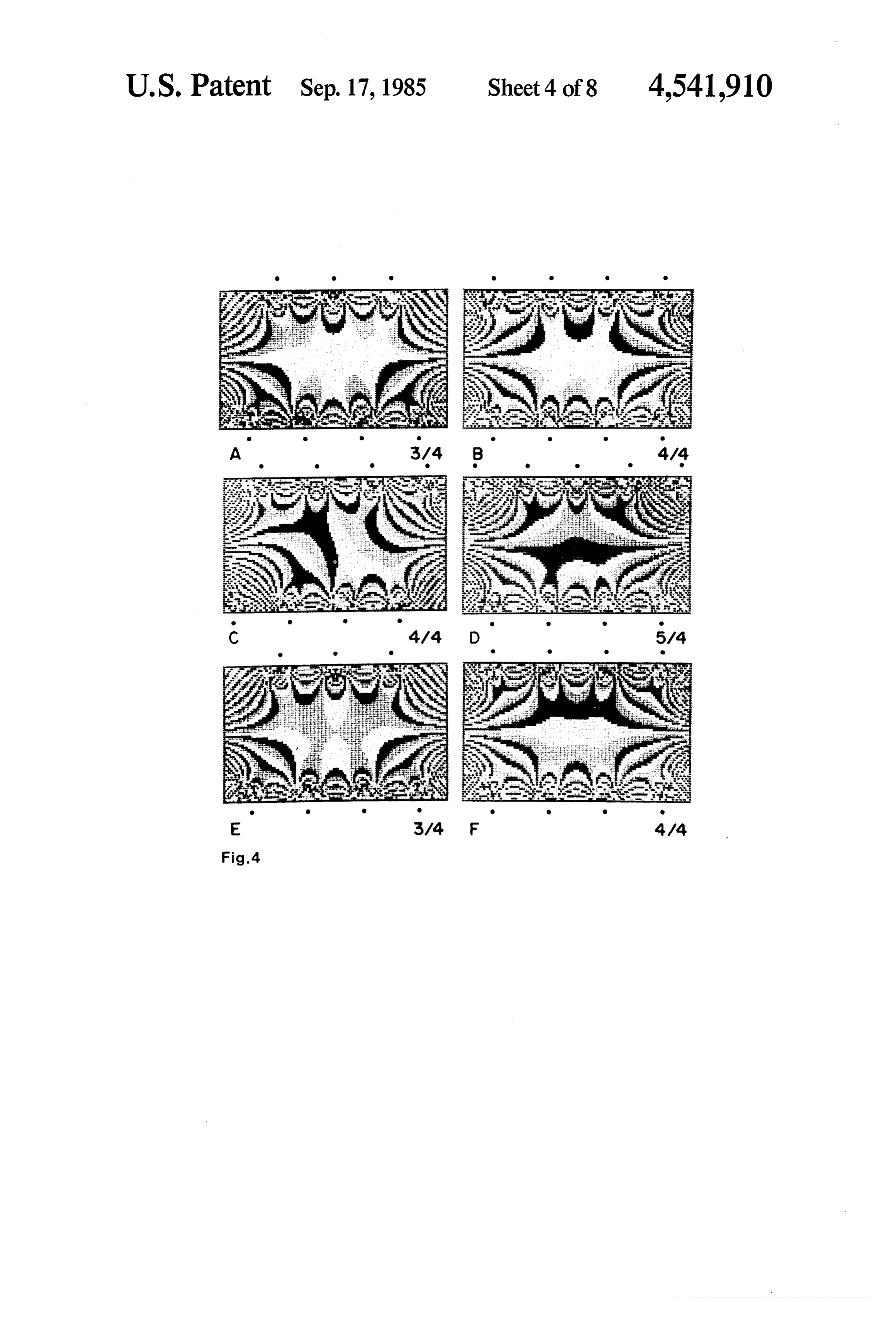
num wire as the electrode. In practice, arrays of various commercially available) were made. These measure configurations have been employed. The goal in routing ments clearly indicate that prior to this invention uni the platinum wires comprising the electrode arrays of form electric fields were not produced at the surface of opposite charge was to use as little material as possible the gel. An actual demonstration of the extensive varia while at the same time attempting to route them so as to 5 tion in the electric field intensity measured in a commer produce a uniform field. No direct measurements of the cially available transfer apparatus which utilized an field intensities produced by the various configurations asymmetric electrode array design of three continuous of electrode arrays have been reported. Aside from the horizontal lengths of platinum wire opposing two stag qualitative evidence (cited in the Prior Art section) for gered horizontal lengths in which all the vertical cross the production of a uniform field with a particular elec O connections are exposed is graphically reported in FIG. trode configuration the uniformity of the field produced 2. FIG. 2 plots the volts measured (electric field) vs. the over the surface of the gel by other electrode configura distance from the surface of the buffer toward the bot tions is unknown. tom of the box. The arrows in the accompanying elec To facilitate the design of an electrode array which trode diagrams show the position of the probe for each would be efficient in the use of the electrode material 15 scan. All scans of the field in the median frontal plane of but would also produce the desired uniform field at the the apparatus, run perpendicularly to the electrodes, frontal median plane a computer model was developed show single or complex peaks in the center of the box which permits the analyses of the electric fields of a and fall off unevenly at the top and bottom. Deviations very large number of simulated electrode arrays con in the field strength are quite prominent even when the fined within a nonconductive box. Based upon these 20 median frontal plane is scanned parallel to the main data an electrode array has been designed that generates lengths of this electrode array. either a highly uniform or a controlled gradient of field To prove that nonuniform electric fields do adversely intensity. This capability to generate a gradient can affect both qualitatively and quantitatively the transfer provide an efficient solution to a major problem in mac of macromolecules from chromatographic gels, a series romolecule transfer that stems from the fact that elution 25 of transfers from gels containing a uniform suspension efficiency of a macromolecule is related inversely to of a radioactive macromolecule were performed (FIG. molecular weight. Since the gradient electric field can 3). These polyacrylamide gels containing uniform sus assume a variety of shapes the gradient can be tailored pensions of radioactive protein were prepared by solu to experimental needs. bilizing 1-2 uCi 125I-labeled bovine serum albumin in 0.9 A device was constructed to allow the direct mea 30 ml of 10% aqueous SDS. This preparation was added to surement of an electric field at various positions within 89.1 ml of a 10% acrylamide in Tris-HCl buffer pH 8.8 the nonconductive box of a transfer apparatus. The and the resulting mixture was polymerized to yield a device consists of a probe and a mounting mechanism 10% polyacrylamide gel containing 0.1% SDS and a that could be used to accurately position the probe uniform suspension of radioactive protein. This is dem vertically and horizontally. The probe consists of two 35 onstrated by the autoradiogram of such a gel in FIG. square pieces (0.25 cm2) of 15 mill platinum foil which 3A. These gels were then used for transfer to membrane are mounted parallel 1 cm. apart from each other each filters. The autoradiograms of such filters demonstrate on the end of a calibrated plexiglass rod. The squares of the topography of the electric field generated in the platinum foil are connected via Teflon insulated wire to particular transfer apparatus being tested. A uniform a voltmeter or other measuring device such as a con 40 electric field produces uniformly exposed autoradio puter. The mounting mechanism consists of a clamp grams (FIG. 3C) whereas autoradiograms produced which is mounted on a calibrated horizontal track and from transfers conducted with nonuniform electric which holds the probe. The horizontal position of the fields will produce autoradiograms with varying de probe can be determined manually or by a computer. grees of exposure. FIG. 3B is the autoradiograms of the The probe could be adjusted horizontally and vertically 45 blot obtained by transferring such a gel in the apparatus in a reproducible manner anywhere within the noncon analyzed in FIG. 2. The variations measured are re ductive box of the transfer apparatus. To test the effi flected as differential efficiency in transfer of 125I cacy of the device to measure the change in the electric labeled bovine serum albumin. That such peaking in the field as a function of the input voltage to the electrode center of the frontal plane appears to be a characteristic array, the series of measurements plotted in FIG. 1 were 50 trait to asymmetric arrays in general is demonstrated in made. The plot demonstrates that the potential differ the computer simulations (FIG. 4).
ence measured between the two squares of platinum foil Computer simulation of the electric fields generated was directly proportional to the electrical input to the by different designs of electrode arrays is based on the transfer apparatus. The measured voltages are consid mathematical expression which is derived from basic ered to reflect the average field intensity of the region 55 principles of electrostatics. A computer model was of the nonconducting box in which the probe is sus generated by defining the boundaries of a non-conduc pended. tive box and the locations and the coordinates of elec Each electrical measurement and each transfer re trode elements within it. The computer scans over a cited in this application is conducted using 15.6 mM selected plane within the confines of the box and calcu Tris, 120 mM glycine pH 8.3 as electrode buffer and a 60 lates the potential generated by the electrode elements power supply which provides 200 mA constant current. at each point on the plane. This value is then quantized Measurements are made while stirring the buffer thus into 0.2 volt intervals. The levels are then plotted onto reducing the effect of bubbles that otherwise accumu the display at the specified coordinates. To facilitate late around the electrode wires. visual observation, the output is transposed into three To determine whether in fact uniform electric fields 65 grey scale values and printed. The potential change are produced, direct measurements of field intensities from one grey scale value to the next is 0.2 volts. generated by a variety of transfer apparatus equipped For each simulation the box dimensions and electrical with different configurations of electrode arrays (some input have been kept constant. FIG. 4A-F depict the
Page 14
topography of the electric field in the median transverse the most preferred embodiment, these connecting wires plane generated by pairs of electrodes within a box are omitted altogether. The electrode array consists of where the anode consists of four vertical lengths and an equal number of independent, aligned wire lengths, the cathode of three, four, or five lengths as indicated. equally spaced from one another mounted to the walls The positions of the electrode elements can be deter 5 of the box. Whether the aligned wires are to be mounted mined from the reference points designated beyond the horizontally or vertically depends on the orientation of walls of the box. The median of the plane is the plane the chromatographic gel. The spacing between the where uniform electric fields would be expected. Note aligned independent wires depends on the number of that the four elements of the cathode and the anode in aligned wire pairs and the dimensions of the box. In the FIG. 4C are staggered and compare this array to the 10 most preferred embodiment the box is the same dimen directly aligned elements as in the case for FIG. 4B. sions as previously described. In the most preferred The increase in nonuniformity with nonalignment is embodiment 5 independent pairs of aligned electrodes dramatic. The contribution to the field from the con are employed. The aligned pairs are equispaced from necting wires between the elements has been accounted each other and from the side walls of the box. When all for in FIG. 4A-D. FIG. 4E-F depict the same elec 5 five pairs of electrodes are connected directly to the trode configuration as FIG. 4A-B respectively, how power supply they function as would be expected of a ever, the connecting wires are insulated and do not continuous wire electrode with 5 horizontal lengths and affect the electric field. It is apparent from FIG. 4 that insulated connecting wires.
the most promising electrode configuration is the sym In addition to providing highly homogeneous fields metrical 4X4 array. Further fine tuning of this array is 20 this electrode arrangment offers the possibility of gener accomplished by placing the outer electrode elements in ating controlled variable fields of which linear gradient a plane deeper into the box bringing them closer to each fields are of particular interest. Field gradients may be other, thereby increasing the field directly between generated in a variety of ways both mechanical and them. This has the effect of broadening as well as ex electrical. Some mechanical means include tilting the tending considerably the region of uniformity into other 25 electrode array such that one end, for example the bot medial frontal planes. tom end, has a closer distance from anode to cathode Utilizing the results from the computer simulation of than the other end. The bottom end would therefore the electric field from various configurations of elec have a higher field intensity although it would be more trode arrays, a transfer box equipped with the symmet difficult to adjust reproducibly. Another mechanical rical 4x4 configuration of an electrode array was con 30 means would employ a mask to be sandwiched between structed and tested. The nonconductive box measures the chromotographic gel-membrane filter assembly and 10X 16X24 cms. Four vertical lengths of a continuous an electrode. The characteristics of this mask would be platinum wire opposed directly a second array of four to have a variable degree of electrical impedance from vertical lengths identical to the first, the electrodes in one end to the other. Such a characteristic could be each pair being placed the same distance from the sides 35 obtained either through the manipulation of the mask of the box. The length of each vertical wire was 20.5 composition or by varying the porosity of the material cm. gel. The diameter of the wire was 14 mil. The two from one end to the other. The net result of the mask outer most lengths of each electrode wire were posi placed in a homogeneous field would be to generate a tioned 0.3 cm closer to the median frontal plane of the controlled gradient over the surface of the gel. Such box than were the other two lengths which were di 40 masks would be expensive to manufacture and separate rectly against the surface of the wall. The distance be masks would be necessary to create different gradient tween each of the four vertical lengths was 4 cms. All fields. Yet another mechanical means of producing a the cross connecting wires were insulated and thus did gradient would be a system to physically remove the not contribute to the electric field. The distance be chromatographic gel-membrane filter assembly from tween the anode and the cathode was 7.5 cm. FIG. 5 45 the buffer with the electric field at a controlled rate. shows the measured electric field in this transfer box. The net effect of such a system would be to cause a The field was measured across the frontal median planevariable exposure time to the electric field. Thus the at 5 depths (every 4 cm; each depth is designated by achromatographic gel first removed at the top would different symbol) from the buffer surface. The plot receive the least exposure while the bottom of the chro demonstrates the uniformity of the field. Computer 50 matographic gel would receive the applied field for the generated "field maps" of such a box are presented in full time duration. Though this system would work, it is FIG. 6. (A is the frontal median plane, B is 0.5 cm off laden with problems, not the least of which is the drying the median plane, C is the median saggital plane, and D of the gel once it is removed from the buffer. is the median transverse plane). The uniformly dark One electrical means of producing a gradient field ened autoradiogram shown in FIG. 3C demonstrates 55 would be to provide independent power sources for that this apparatus gives a uniform transfer of 125I each electrode pair. Such a system would provide an labeled bovine serum albumin. This configuration of easy means to manipulate the gradient but would be electrode wires ensures that a uniform electric field can prohibitively expensive to become practical. Another be reliably and reproducably generated. This ensures electrical means would be to use a single power source that quantitative transfers of macromolecules of the 60 but a system of independent voltage or current regula same molecular weight in every lane in a chromato tors for each electrode pair. This would maintain the graphic gel will occur. ease of adjustment of the former method and would be Measurements of the electric fields generated by the less expensive. A simpler method still is to provide electrode array of the same configuration but with insu either fixed resistors in series with each electrode pair lated or uninsulated connecting wires indicates clearly 65 which could then be switched to establish different that wider, more symmetrical and more uniform fields gradients or a set of variable resistors for each electrode are obtained in the frontal central region of the box pair so that the field could be continuously varied. The when the connecting wires are insulated. Therefore, in method employed in the most preferred embodiment of
Page 15
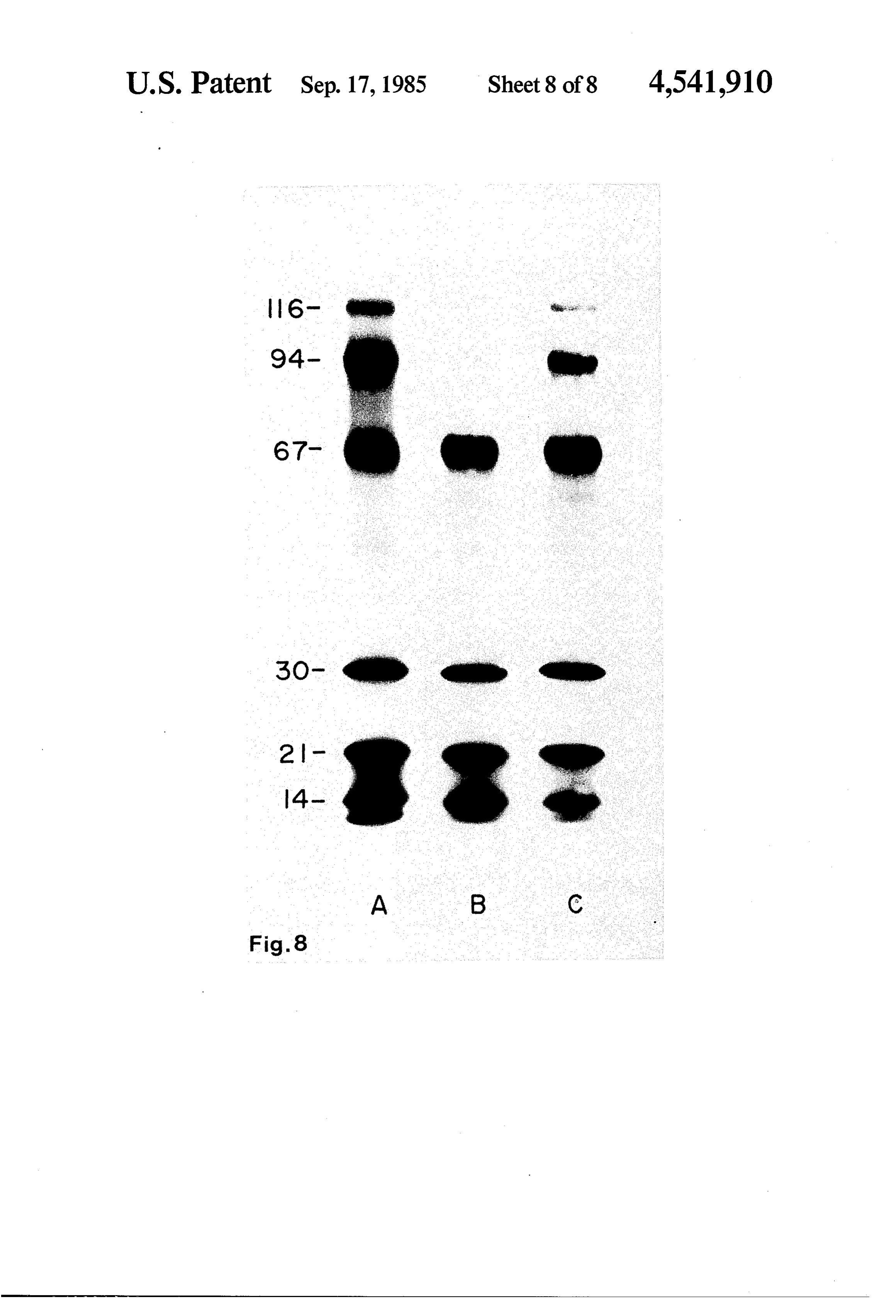
the invention uses a combination of the above methods cally diminished in quantity. This is in contrast to the a switch selects fixed resistors for preset gradients as linear gradient field (15-65 volts) in which a more uni well as potentiometers for continuously variable gradi form and therefore a more quantitative transfer of all of ents. the components from the gel is obtained (compare A to Whether setting variable gradients with potentiome- 5 C). Therefore, gradient fields provide two very signifi ters or observing the effects of chromatographic gels in cant advantages. First, there exists the possibility of uniform fields, it is extremely useful to monitor the preferentially accelerating the high molecular weight applied potentials at each electrode pair. This capability proteins while slowly eluting the low molecular weight is realized in the preferred embodiment of this invention proteins. Slow transfer of the smaller proteins is found through the use of a voltmeter, either housed within the 10 to be advantageous as it gives the macromolecules more control box or attached externally, whose input can be time interact with the matrix material thus limiting the switched to any selected electrode pair in order to mea extent to which they are blown through the filter. Se sure the applied field intensity. It is connected through condly, the gradient allows better use of common the selecting switch directly to the opposing pairs of power supplies. By redistributing the field strength, electrodes after the series resistance to the power sup- 15 high potential differences, e.g., 65 V, can be generated ply. where needed and sufficiently low, e.g., 15 V, provided FIG. 7 is a plot of the electric field measured from top at the lower end of the gradient while still running the to bottom at the frontal median plane. FIG. 7 illustrates system with modest currents, e.g. 200 mA. the utility of the five independent, aligned electrode We claim:
pairs to produce both a very uniform field (solid dots) 20 1. An improved method of electroblotting macromol and gradient fields (solid squares, 65 V-15 V; open ecules from a chromatographic gel to an immobilizing squares, 40 V-20 V). matrix wherein the improvement comprises: To demonstrate the effect of the molecular weight of (a) measuring the electric field produced by two or a macromolecule on its transfer from a gel, 25I-labeled more sets of electrodes, each set of electrodes com proteins of different molecular weight were used as 25 prising an anode and a cathode which are located standards. These standards were separated on SDS/5- in the same saggital plane within the container, 15% polyacrylamide gradient gels and then blotted to whose electric potential can be varied and adjusted nitrocellulose membrane filters. independent from other said sets of electrodes and FIG. 8 clearly demonstrates the utility of gradient which said sets of electrodes are equispaced from field blotting. As noted above, the speed of electroelu- 30 other said sets of electrodes; and (b) exposing a tion of macromolecules at constant current is inversely chromatographic gel and immobilizing matrix proportional to their molecular weight (the numbers in placed in a non-conductive container containing a FIG. 8 designate molecular mass in kilodaltons). If the buffer to the measured electrical field. voltage, current and time conditions are selected so as 2. An improved method as in claim 1 wherein the to optimize the electroelution of the lower molecular 35 electric potential of each said set of electrodes is varied weight macromolecules, the larger molecular weight to produce an electric field as measured at the gel components are retained by the gel. If the voltage, cur matrix interface.
rent and time conditions are optimized to elute the high 3. An improved method as in claim 1 wherein the molecular weight components, the lower molecular electric potential of each said set of electrodes is varied weight components are eluted so rapidly that they can- 40 to produce the same electric field at the gel-matrix inter not be retained by the immobilizing matrix. FIG. 8 face.
compares gradient field electroelution (C) with the 4. An improved method as in claim 1 wherein the conventional method of uniform field (25 volts, B) elec electric potential of each said set of electrodes is varied troelution (A, is an autoradiogram of a sample gel prior to produce an electric field which increases linearly to transfer). It is apparent in the uniform field transfer 45 along the gel-matrixckinterface. that high molecular weight components are dramati : ck ck ck
Provenance
- Collection
- Cited prior art
- Original PDF
- patentimages.storage.googleapis.com →
- Filed
- 1983-11-07
- Pages
- 15
- Method
- pdftotext (the PDF's own text layer) + pdftoppm 300dpi page scans
- Source
- Google Patents bibliographic record
- Granted
- 1985-09-17
- Inventors
- Fred E. Davis, III; Johathan M. Gershoni; Yale University
- Transcribed from
- patentimages.storage.googleapis.com →