patent · US4367700
Apparatus for insuring the complete burning of fuel in a six cycle combustion engine
11 January 1983
Page 1 — bibliographic record
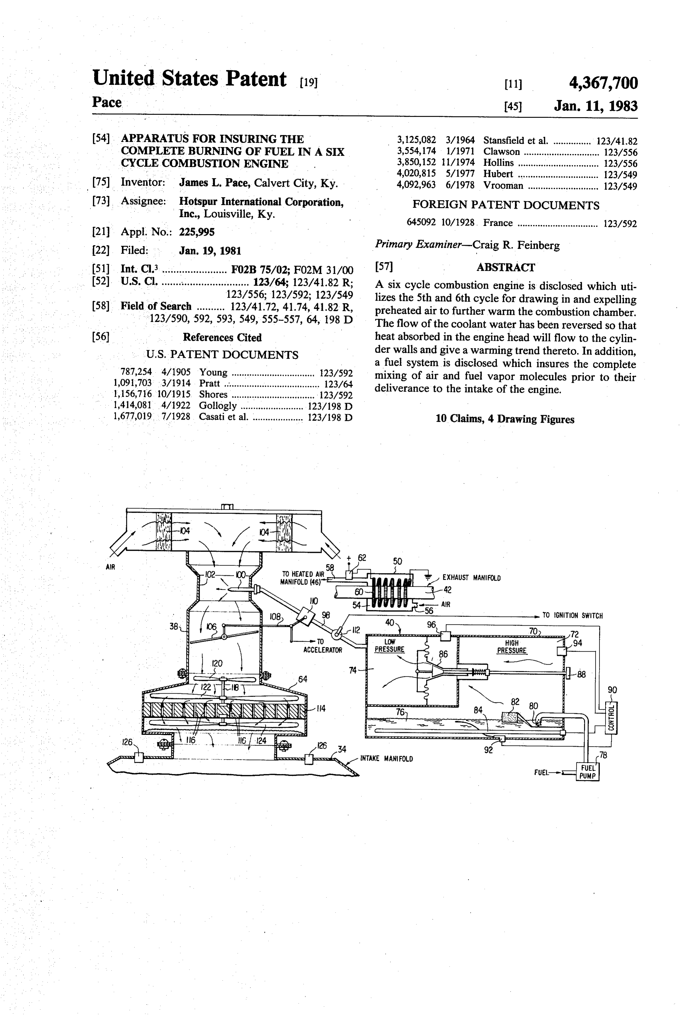
United States Patent (19) 11) 4,367,700 Pace 45 Jan. 11, 1983 (54) APPARATUS FOR INSURING THE 3,125,082 3/1964 Stansfield et al. ....... ... 123/41.82 COMPLETE BURNING OF FUEL IN A SIX 3,554,174 1/1971 Clawson ... ... 123/556 CYCLE COMBUSTION ENGINE 3,850,152 11/1974 Hollins ..... ... 123/556 4,020,815 5/1977 Hubert ..... ... 123/549 (75) Inventor: James L. Pace, Calvert City, Ky. 4,092,963 6/1978 Vrooman ............................ 123/549 (73) Assignee: Hotspur International Corporation, FOREIGN PATENT DOCUMENTS Inc., Louisville, Ky. 645092 10/1928 France ............................... 123/592
22) Filed: Jan. 19, 1981 Primary Examiner-Craig R. Feinberg (51) Int. Cl........................ F02B 75/02; FO2M 31/00 57 ABSTRACT (52) U.S. Cl. ....... a as . . . . . . . so as a 123/64; 123/41.82 R; A six cycle combustion engine is disclosed which uti 123/556; 123/592; 123/549 lizes the 5th and 6th cycle for drawing in and expelling (58) Field of Search .......... 123/41.72, 41.74, 41.82 R, preheated air to further warm the combustion chamber. 123/590,592, 593, 549, 555-557, 64, 198 D The flow of the coolant water has been reversed so that (56) References Cited heat absorbed in the engine head will flow to the cylin
a fuel system is disclosed which insures the complete 787,254 4/1905 Young ................................. 12.3/592 mixing of air and fuel vapor molecules prior to their 1,091,703 3/1914 Pratt ...................................... 123/64 deliverance to the intake of the engine. 1,156,716. 10/1915. Shores ................................. 123/592 1,414,081 4/1922 Gollogly ... ... 123/198 D 1,677,019, 7/1928 Casati et al. .................... 123/198 D 10 Claims, 4 Drawing Figures
AIR
TOGNITION SWITCH
HIGH
PRESSURE
DEn
NNNNN SN 84
Page 2
Drawing sheet — no readable text.
Page 3
Drawing sheet — no readable text.
Page 4
Drawing sheet — no readable text.
Page 5
APPARATUS FOR INSURING THE COMPLETE and advantages thereof will be better understood from
BURNING OFFUEL IN A SIX, CYCLE,
the following description considered in connection with the accompanying drawing in which a presently pre
COMBUSTION ENGINE ferred embodiment of the invention is illustrated by way
BACKGROUNDINVENTION
AND OBJECTS OF THE of example. It is to be expressly understood, however, that the drawing is for the purpose of illustration and description only, and is not intended as a definition of
This invention relates to internal combustion engines and more specifically to a novel engine design and fuel the limits of the invention.
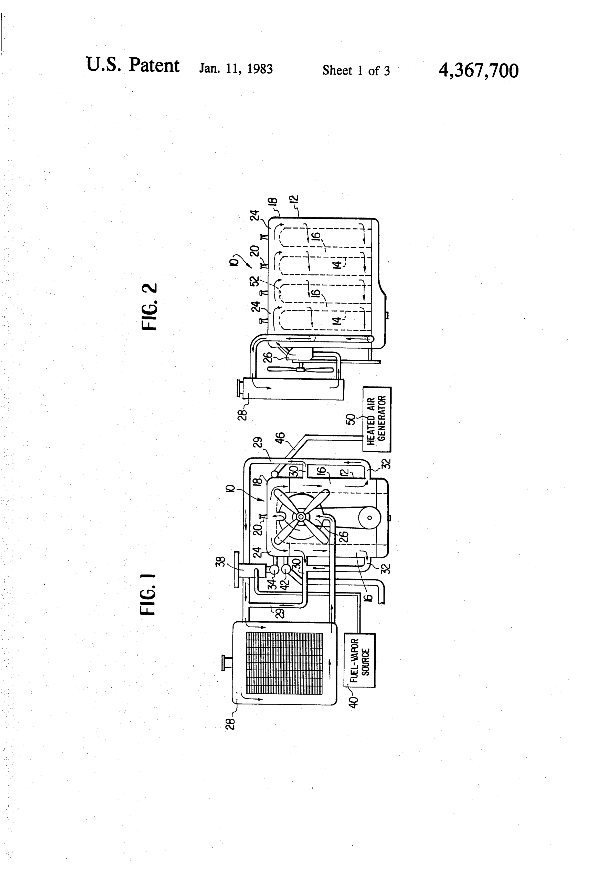
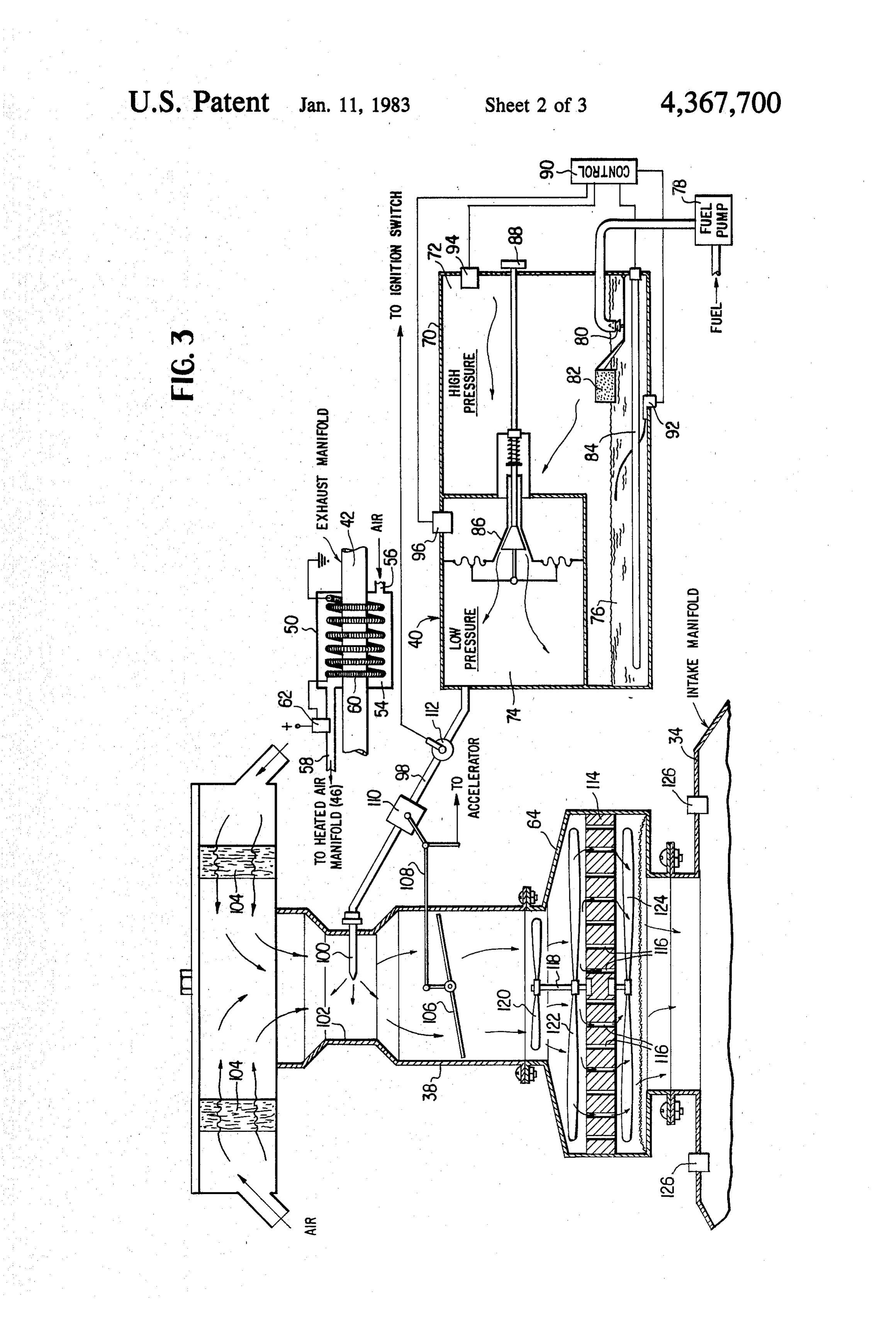
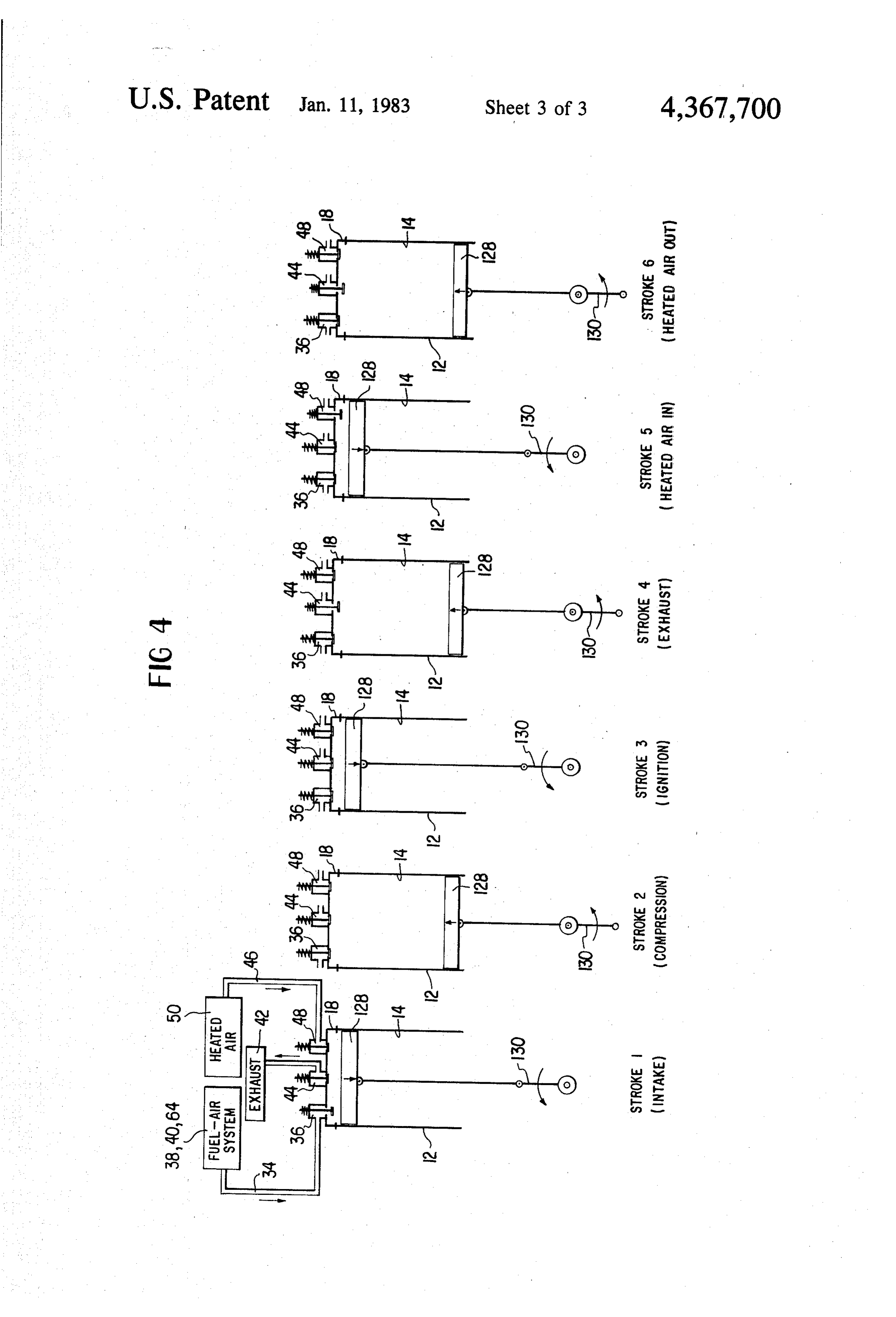
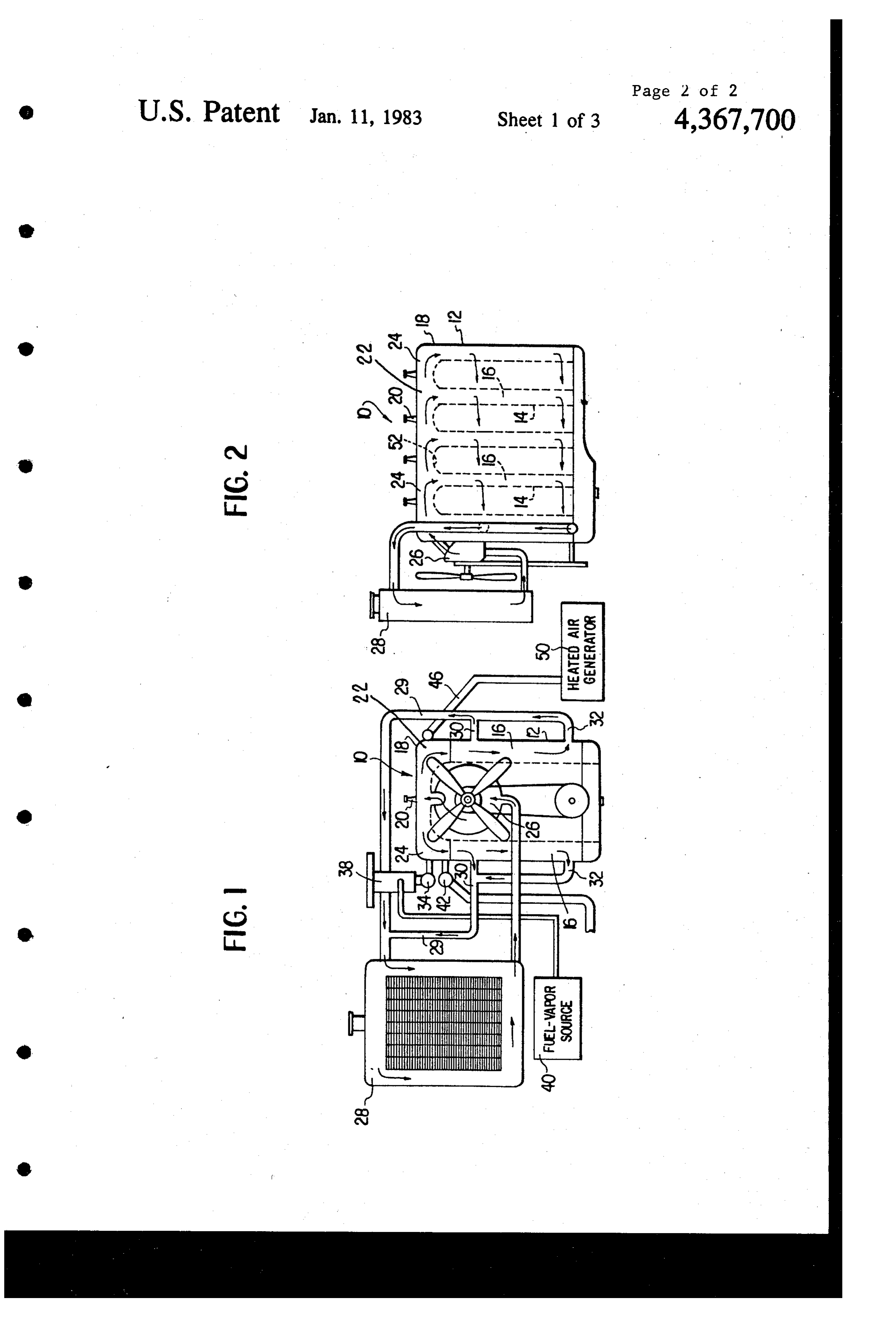
system therefore. . ... . . 10 BRIEF DESCRIPTION OF THE DRAWINGS It is the primary object of this invention to provide an FIG. 1 is a front elevational view of an internal com improved internal combustion engine and fuel system bustion engine showing the direction of coolant flow therefore which exhibits very high efficiency and low according to the principles of the present invention. hydrocarbon emission characteristics due to a near per fect combustion of the admixture of air and fuel forming 15 1. FIG. 2 is a side elevational view of the engine of FIG.
This is achieved by providing a six cycle engine hav forFIG. an 3 is a schematic illustration of the fuel system internal combustion engine according to the ing a heat exchanger which furnishes heated air to the invention.
cylinders on the 5th stroke to further heat same and FIG. 4 is a diagrammatic illustration of an internal which air is expelled on the 6th stroke. In addition, the 20 combustion flow of coolant in the engine has been changed from the preheated airengine is having a six stroke cycle wherein introduced during the 5th cycle.
conventional method of absorbing heat from the cylin der walls first and then the engine head to permitting DESCRIPTION OF THE INVENTION the coolant to absorb heat from the engine head first and transfer this heat to the cylinder wall to impart a warm 25 Referring now to the drawings where like characters ing trend thereto. A new fuel system is also disclosed of reference refer to like elements in each of the several views, FIGS. 1 and 2 show a conventional four cylinder which ensures that the mixture of fuel and air is as com plete as possible before entering the intake manifold of internal combustion engine 10 of the six stroke cycle the engine. type it being understood of course that the number of The prior art structure of which applicant is aware is 30 cylinders, can be increased or decreased without depart exemplified, for example, in U.S. Pat. No. 2,355,806 ing from the spirit of the invention, and four are shown which discloses a six cycle engine wherein additional in FIG. 1 for the purpose of illustration. The engine 10 air is introduced on the 5th stroke and expelled on the has a block 12 with cylinder walls 14 surrounded by 6th stroke. However, the air is substantially cool and is passageways 16 through which a coolant is passed. The introduced to reduce the temperature of the cylinder 35 engine 10 also has a head 18 containing the spark plugs head and walls to prevent preignition and not for the 20 and valving 22 positioned above the block 12. The purpose of controlling the inner skin surface to inhance head 18 has passageways 24 therethrough which com combustion as does applicant. Another U.S. Pat. No. municate with passageways 16 in the block. The pas 3,964,263 discloses a six cycle engine which teaches the sageways 24 in the head 18 are connected to an engine use of fins to increase the temperature inside the com driven coolant pump 26 which in turn is connected by a bustion chamber, however, the purpose is to readily hose to a radiator 28 at one end thereof. The other end vaporize a liquid such as water which is introduced of the radiator 28 is connected by hosing 29 to upper during the fourth stroke of the engine and not to in outlet 30 and lower outlet 32 in the block 12 which crease the temperature of the inner skin surfaces to outlets communicate with passageways 16 there enhance combustion of the air and fuel mixture as does 45 through.
applicant. . Typically, because the highest degree of heat in an It is therefore a further object of the present invention internal combustion engine is generated in the head 18 to provide a six cycle internal combustion engine which and the portion of the cylinders adjacent thereto, the utilizes heated air introduced on the 5th cycle thereof to flow of coolant has been first through the block pas increase the inner skin surface temperature of the head 50 sageways 16, then through the head passageways 24 and and cylinder walls to facilitate more complete combus back to the radiator 28. However, because applicant has tion of the charge. discovered that additional heat along the length of the It is another object of the present invention to pro cylinder walls 14 materially aids in ensuring the com vide an internal combustion engine with a reversed plete combustion of the fuel and air mixture fed thereto coolant flow therethrough to inhance the internal tem 55 with the resultant increase in efficiency and decrease in perature of the cylinder walls to further improve com hydrocarbon emissions, the direction of coolant flow
has been reversed as can be seen by the arrows in FIGS.
It is a yet another object of the present invention to 1 and 2. More specifically, the coolant is caused by provide an improved fuel system for an internal com pump 26 to enter the head passageways 24 first where bustion engine and one which insures the thorough upon heat is absorbed by the coolant. As the heated mixing of the air and fuel forming the charge. coolant travels to the passageways 16 in the block 12, It is a still further object to provide an internal com the head absorbed therein provides a warming trend to bustion engine of 6 cycle type which is of simple con the cylinder walls 14 prior to its exit through outlets 30, struction, economically feasible, and relatively, trouble 32 and return to the radiator 28 via hose 29. free in operation. 65 The engine 10 has a fuel and air intake manifold 34 The novel features which are believed to be charac connected at one end to each intake valve 36 and at the teristic of the invention, both as to its organization and other end to a fuel-air supply system comprising a car method of operation, together with further objectives buretor 38 and a source of low pressure vaporized fuel
Page 6
40. The engine 10 also has a conventional exhaust mani The electrical resistance-type heating element 84 is fold. 42 connected at one end to each exhaust valve 44 connected to a control 90 which determines when the and at the other end to a conventional muffler system heating element 84 will be energized. The control 90 (not shown). In addition, the engine 10 has a heated air operates in response to the temperature of the fuel 76 as manifold 46 connected at one end to each heated air measured by adjustable temperature sensor 92 and the inlet valve 48 and at the other end to a heated air gener pressure senses by high pressure sensor 94 and low ator 50. pressure sensor 96. Sensors 92,94 and 96 are electrically The heated air generator 50 serves the function of connected in series to control energization of heating supplying a quantity of warm air to the cylinders walls element 84. The setting of sensor 92 is determined by 14 of the engine to insure that the walls 14 as well as the the characteristics of the particular fuel being used inner surface 52 of the head 18 is at a constant, prese whereas pressure sensors 94 and 96 are chosen for opti lected temperature at all times to enhance the combus mum safety and pollution considerations. tion efficiency of the air-fuel mixture burned therein. The low pressure chamber 74 is connected by piping The generator 50 as disclosed in FIG. 3 comprises a 98 to the carburetor 38, and more specifically, to a jet housing 54 which surrounds a portion of the exhaust 15 100 in the throat 102 of the carburetor. Air drawn into manifold 42. The housing 54 has an inlet 56 for intro the throat 102 through filter 104 is controlled by means ducing air to the interior thereof and an outlet 58 con of the butterfly throttle valve 106 in the conventional nected to the heated air manifold 46. An electric resist manner. A linkage 108 connects the throttle valve 106 ance-type heating element 60 is located within the hous with a vapor flow control valve 110 in piping 98 which ing 54 and it is connected to a source of current (not 20 linkage 108 is in turn connected to an actuator (not shown) via a thermostatically controlled switch 62 shown) such as an accelerator pedal. A solenoid acti which senses the temperature in outlet 58 to thereby vated switch 112 is also provided in piping 98 which is control energization of the heating element 60. In oper connected to and activated to its open and closed posi ation, prior to the exhaust manifold 42 reaching its nor tion when the ignition switch of the vehicle is respec mal operating temperature as the engine 10 is started up, 25 tively in its on or off position. Thus, the molecules of the switch 62 will energize the heating element 60 to fuel vapor entering the throat 102 via jet 100 from low warm the air being drawn through inlet 56 prior to its pressure chamber 74 is combined with air molecules in introduction to the cylinders via inlet valves 48. As the the throat 102 of carburetor 38. This combination of air exhaust manifold 42 reaches operating temperature, the and fuel molecules is then drawn to the mixing device heating element 60 is deenergized and the air from inlet 30 64 by the suction existing in intake manifold 34. 56 is heated directly by the exhaust manifold 42 itself. The mixing device 64 comprises a screen 114 having The air in outlet 58 is maintained typically in excess of a plurality of mixing holes 116 which are, for example, 100 F. 1/64 inch in diameter. A shaft 118 is secured to the In addition to the aforedescribed ways of insuring screen 114 and has a first propellor 120 and a second that the cylinder walls 14 and inner surface 52 of head 35 propellor 122 rotatably mounted on one section thereof 18 are at a higher temperature than normally experi above the screen 114 and a third propellor 124 rotatably enced in conventional internal combustion engines, mounted on the section of the shaft 118 beneath the namely by the reversal of the coolant flow from the screen 114. The direction of the pitch of the propellors head passageways 24 to the cylinder passageways 16 120, 122 is chosen such that they are caused to rotate and the heated air injected through valve 48 from gen 40 counter to each other as the fuel and air combination is erator 50, the fuel-air mixture forming the charge intro drawn around and past them into mixing holes 116. duced into the intake manifold 34 is also novel thereby Propellor 124 is also caused to rotate as the thoroughly insuring greater combustion efficiency than previously mixed combination of fuel and air molecules is drawn experienced. The charge is formed, generally speaking, past it into intake manifold 34. The counter rotation of by combining vaporized fuel preferably of the no-lead 45 propellors 120,122, mixing holes 116 and rotating pro type from generator 40 with air in the carburetor 38 and pellor 124 thoroughly mixes the combined vaporized then thoroughly mixing the combined air and vaporized fuel molecules and air molecules to form a charge fuel molecules in a mixing device 64 prior to their en which when introduced into the cylinders already trance into intake manifold 34. It being understood of heated according to the aforedescribed principles and course that fuels other than gasoline can be used just as SO means of the present invention, result in complete com effectively in forming the charge. bustion during the power stroke with the resultant sub More specifically, the source of vaporized fuel 40 stantial increase in power and overall operating effi consists of a housing 70 having a high pressure chamber ciency. This is in contrast to most conventional internal 72 and a low pressure chamber 74. The high pressure combustion engines which burn as much fuel on the chamber has a quantity of low lead or preferably no 55 exhaust stroke as on the power stroke or the fuel is not lead fuel such as gasoline 76 in the bottom thereof. The burned at all but carried out in the exhaust. Relief values fuel 76 is introduced to the high pressure chamber 72 by are provided in the wall of the intake manifold 34 to means of a pump 78 via a valve 80 which is opened and permit the release of pressure from the manifold in the closed by means of a float 82 in a well known manner. event of a premature ignition of the fuel in the manifold A sealed electrical resistance-type heating element 84 is 60 itself causing a backfire.
positioned in the fuel 76 to heat same to the point where OPERATION the fuel turns into a vapor. A pressure activated valve 86 is provided between the high pressure chamber 72 Referring to FIG. 4, the operation of the six stroke and low pressure chamber 74 to permit fuel vapor to cycle engine 10 will be described assuming the direction enter the low pressure chamber 74 when the pressure of 65 of coolant flow as previously discussed which results in the fuel vapor in the high pressure chamber 72 reaches a higher and more even distribution of heat the length of a predetermined or preselected amount which can be the cylinder walls. The engine has three values, and controlled by knob 88. intake valve 36, an exhaust valve 44 and a heated air
Page 7
inlet valve 48 all activated by conventional caming and valve being opened during said fourth cycle of said the like, which in the interest of clarity has been elimi piston for removing therefrom the products of nated in the drawings. The cylinder 14 has a reciprocat combustion and opened during said sixth cycle of ing piston 128 connected to a crankshaft 130 in a well said piston for removing said preheated air. known manner. The fuel intake valve 36 and manifold 5 2. In an internal combustion engine as set forth in 34 are connected to the aforedescribed fuel-air system claim 1 wherein said cylinder head and said cylinder comprising vaporized fuel generator 40, carburetor 38 have communicating water passages, said cylinder head and mixing device 64, the exhaust valve 44 is connected having an inlet through which water is introduced to to exhaust manifold 44 and heated air inlet valve 48 is said passages from a source and said cylinder has an connected to heated air manifold 46. 10 outlet adjacent the bottom thereof for returning said The following is the sequence of operation of appli water to said source whereby said water in said cylinder cants' six stroke cycle engine: head passages absorbs heat from said cylinder head Stroke 1 - Intake valve 36 is opened and the prior to its travel to said cylinder where said absorbed throughly mixed charge of fuel and air is drawn into the head in said water is transferred to said cylinder to heat cylinder during the downward movement of piston 128. 15 Sae.
Stroke 2 - All valves are closed and the charge heated 3. In an internal combustion engine as set forth in by the cylinder walls is compressed. claim 1 wherein said intake manifold has pressure relief Stroke 3 - All valves remain closed and the charge is valves associated therewith to permit gasses to escape ignited driving piston 128 down. , therefrom in the event of backfire. Stroke 4- Exhaust valve 44 is opened and burnt gas 20 4. In an internal combustion engine as set forth in ses are expelled during upward stroke of piston 128. claim 1 wherein said means connected to said purge Stroke 5 - Inlet valve 48 is opened and warm air from manifold for supplying preheated air is a heat exchanger generator 50 is drawn into cylinder by the downward in communication with said exhaust manifold wherein movement of piston 128, thereby further increasing the air is drawn over said exhaust manifold to preheat same temperature of the cylinder walls 14 and engine head 25 prior to its introduction to said purge manifold. 18. 5. In an internal combustion engine as set forth in Stroke 6 - Exhaust valve 44 is again opened and the claim 4 wherein said heat exchanger further comprises heated air is expelled. a thermostatically controlled electric resistance element Applicant has thus described his novel six stroke which is energized to preheat said air to be preheated cycle engine and its operation, an engine which 30 prior to the heating of said exhaust manifold by said achieves very high operating efficiency due to the products of combustion.
unique combustion of reversed coolant flow, ingested 6. In an internal combustion engine as set forth in heated air on the 5th stroke of a six stroke cycle, and the claim 1 wherein said means for supplying said mixture completely mixed charge of air and vaporized fuel mol of fuel and air to said intake manifold comprises a means ecules resulting from applicants vaporized fuel genera 35 for transforming liquid fuel into fuel vapor, a carburetor tor, carburetor and mixing device. device for combining said fuel vapor and a quantity of While the invention has been particularly shown and air, and a means for thoroughly mixing said molecules described with reference to the preferred embodiments of fuel vapor with oxygen molecules.
thereof, it will be understood by those skilled in the art 7. In an internal combustion engine as set forth in that various changes in form and details may be made 40 claim 6 wherein said means for transforming liquid fuel therein without departing from the spirit and scope of into molecules of fuel vapor comprises: the invention. (a) a first chamber having means therein for trans What is claimed is: forming liquid fuel into fuel vapor at high pressure, 1. In an internal combustion engine operating on a six (b) a second chamber connected to said first chamber stroke cycle, the combination comprising: 45 by way of a pressure regulated valve means for (a) at least one cylinder having a cylinder wall and a receiving said fuel vapor at low pressure, and cylinder head therefor, said cylinder head having a (c) means for delivering said fuel vapor at low pres fuel and air mixture intake valve, a preheated air sure to said mixing means.
purge valve and an exhaust valve communicating 8. In an internal combustion engine as set forth in with said cylinder, said intake valve, said purge 50 claim 7 wherein said means for transforming liquid fuel valve and said exhaust valve each being connected into fuel vapor at high pressure is an electric heating to a common respective intake, purge and exhaust element the energization of which is controlled in re manifold, sponse to the temperature of said liquid fuel and the (b) a piston operable in said cylinder, vapor pressure sensed in said first and second chambers. (c) means connected to said intake manifold for sup 55 9. In an internal combustion engine as set forth in plying a mixture of fuel and ambient air to said claim 6 wherein said means for thoroughly mixing said cylinder via said intake valve during the first cycle fuel vapor and air comprises a plurality of mixing tubes of said piston, which is then compressed and ex extending in the direction of travel of said combined panded during the second and third cycles, respec fuel vapor and air mixture and first and second freely tively, of said piston, and 60 rotating mixing propellors mounted adjacent one side of (d) means connected to said purge manifold for sup said mixing tubes and a third, freely rotating propellor plying air preheated to a temperature above that of mounted adjacent the other side of said mixing tubes. ambient air to said cylinder for imparting heat to 10. In an internal combustion engine as set forth in said wall of said cylinder to improve subsequent claim 9 wherein said first and second mixing propellors combustion of said mixture via said purge valve 65 counter rotate with respect to seachk other. during the fifth cycle of said piston, said exhaust k k :k
Page 8
UNITED STATES PATENT AND TRADEMARK OFFICE
CERTIFICATE OF CORRECTION
PATENT NO. : 4,367,700 Page 1 of 2
INVENTOR(S) : James L. Pace
It is Certified that error appears in the above-identified patent and that said Letters Patent is hereby Corrected as shown below:
O Figures 1 and 2 should appear as shown on the attached sheet.
Column 5, line 9, "manifold 44' should read -- manifold 42 --.
O eigned and Scaled this Twenty-eighth Da y of June 1983
SEAL
Attest:
GERALD J MOSSINGHOFF
Attesting Officer Commissioner of Patents and Trademarks
Page 9
Drawing sheet — no readable text.
Provenance
- Collection
- Cited prior art
- Original PDF
- patentimages.storage.googleapis.com →
- Filed
- 1981-01-19
- Pages
- 9
- Method
- pdftotext (the PDF's own text layer) + pdftoppm 300dpi page scans
- Source
- Google Patents bibliographic record
- Granted
- 1983-01-11
- Inventors
- James L. Pace; Hotspur International Corp Inc
- Transcribed from
- patentimages.storage.googleapis.com →