patent · US4627405
Apparatus for injecting fuel into combustion chambers
9 December 1986
Page 1 — bibliographic record
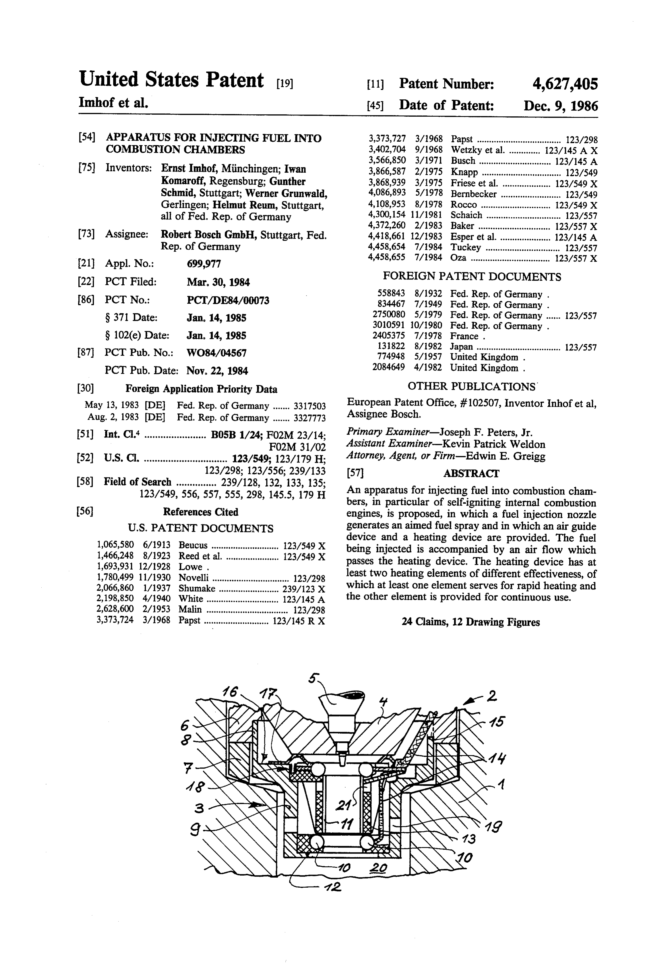
United States Patent (19) 11 Patent Number: 4,627,405 Imhof et al. 45 Date of Patent: Dec. 9, 1986 (54) APPARATUS FOR INJECTING FUEL INTO 3,373,727 3/1968 Papst ................................... 123/298 COMBUSTON CHAMBERS 3,402,704 9/1968 Wetzky et al. . ... 123/145 AX 3,566,850 3/1971 Busch .............................. 123/145 A 75) Inventors: Ernst Imhof, Minchingen; Iwan 3,866,587 2/1975 Knapp ................................. 123/549 Komaroff, Regensburg; Gunther 3,868,939 3/1975 Friese et al. .................... 123/549 X Schmid, Stuttgart; Werner Grunwald, 4,086,893 5/1978 Bernbecker ......................... 123/549 Gerlingen; Helmut Reum, Stuttgart, 4,108,953 8/1978 Rocco ............................. 12.3/549 X all of Fed. Rep. of Germany 4,300,154 11/1981 Schaich ............................... 123/557 4,372,260 2/1983 Baker .............................. 123/557 X 73) Assignee: Robert Bosch GmbH, Stuttgart, Fed. 4,418,661 12/1983 Esper et al. ..................... 123/145 A Rep. of Germany 4,458,654 7/1984 Tuckey ............................... 123/557 4,458,655 7/1984 Oza ................................. 123/557 X
FOREIGN PATENT DOCUMENTS
86) PCT No.: PCT/DE84/00073 558843 8/1932 Fed. Rep. of Germany .
S371 Date: Jan, 14, 1985 2750080 5/1979 Fed. Rep. of Germany ... 123/557
S 102(e) Date: Jan. 14, 1985 2405375 7/1978 France.
131822 8/1982 Japan ................................... 123/557 87 PCT Pub. No.: WO84/04567 774948 5/1957 United Kingdom. PCT Pub. Date: Nov. 22, 1984 2084649 4/1982 United Kingdom. 30 Foreign Application Priority Data OTHER PUBLICATIONS May 13, 1983 (DEl Fed. Rep. of Germany ....... 3317503 European Patent Office, #102507, Inventor Inhofetal, Aug. 2, 1983 DEl Fed. Rep. of Germany ....... 3327773 Assignee Bosch.
51) Int. Cl. ....................... B05B 1/24; F02M 23/14; Primary Examiner-Joseph F. Peters, Jr. FO2M 31/02 Assistant Examiner-Kevin Patrick Weldon 52) U.S. Cl. ............................... 123/549; 123/179 H; Attorney, Agent, or Firm-Edwin E. Greigg 123/298; 123/556; 239/133 57 ABSTRACT
123/549, 556, 557, 555,298, 145.5, 179 H An apparatus for injecting fuel into combustion cham bers, in particular of self-igniting internal combustion 56) References Cited engines, is proposed, in which a fuel injection nozzle
1,065,580 6/1913 Beucus......... ... 123/549 X device and a heating device are provided. The fuel 1,466,248 8/1923 Reed et al. ....... ... 123/549 X being injected is accompanied by an air flow which 1,693,931 12/1928 Lowe. passes the heating device. The heating device has at 1,780,499 11/1930 Novelli................................ 123/298 least two heating elements of different effectiveness, of 2,066,860 1/1937 Shumake .. ... 239/123 X which at least one element serves for rapid heating and 2,198,850 4/1940 White ........... ... 123/145 A the other element is provided for continuous use. 2,628,600 2/1953 Malin .................................. 123/298 3,373,724 3/1968 Papst ........................... 123/145 RX 24 Claims, 12 Drawing Figures
Page 2
Drawing sheet — no readable text.
Page 3
Drawing sheet — no readable text.
Page 4
Drawing sheet — no readable text.
Page 5
Drawing sheet — no readable text.
Page 6
Drawing sheet — no readable text.
Page 7
when it is additionally intended to improve combustion
APPARATUS FOR NJECTING FUEL INTO during continuous operation. This may be necessary at COMBUSTON CHAMBERS very low ambient temperatures, for example, but it may
STATE OF THE ART
also be provided in the field of oil burning, to generate a blue flame.
The invention is based on the apparatus for injecting In contrast to the cold-start heating device, a heating fuel into combustion chambers as generically defined device for continuous operation should have the lowest hereinafter. In a known apparatus of this type (French possible wattage or power and should have a heat-stor Pat. No. 1 382 697), the fuel is conducted through a ing effect. The demand for the smallest possible power tubular heating device shortly before or after injection, 10 consumption is primarily based on energy consumption in order thereby to maintain a temperature facilitating but secondarily on the energy-dependent wear as well. ignition. One disadvantage in this known apparatus is A storage effect is particularly desirable in internal that heating of the fuel occurs before the fuel meets the combustion engines in which the fuel is injected inter combustion air, and another is that the virtually diver 15 mittently and the heat dissipation is accordingly inter gent conditions for cold-start heating and for constant mittent as well. Thus in the intervals for heat dissipa heating during operation must be satisfied with merely tion, a reheating of the cooled element may occur. Ad a single heating element. When fuel alone is heated, it is ditionally, in an internal combustion engine, heating and absolutely necessary that the heating temperature not cooling phases may alternate in rapid succession, de be too high, so as not to cause decomposition of the fuel pending on the power produced by the engine itself, in the absence of combustion air and subsequent carbon 20 and in that case heat storage is advantageous. ization, or even carbonization in the vicinity of the first Other devices of this generic type are also known, for air inlet-that is, at the injection port-because of the instance glow plugs or pins which are built into the sudden availability of combustion air, which can cause combustion chamber. In the vicinity of their tips, they a change in the injection port and in every case has create favorable extraordinarily disadvantageous effects on the course of igniting a partial conditions
quantity of for heating, vaporizing and the fuel, which then ingites combustion in the combustion chamber. The quantity of the entire fuel spray.
fuel to be injected is a function of the pressure and the However, glow plugs and pins are separate parts, and cross section, and it is metered in accordance with a predetermined quantity of combustion air in the com installing them in combustion chambers means an inter bustion chamber. As soon as changes in the predeter 30 vention into sensitive flow conditions. The trend mined fuel/air ratio occur as a consequence of changes toward alternative fuels such as alcohols and vegetable in the cross section of the injection port, this has a direct oils, which has been reinforced by the energy shortage, effect on the quantity of combustion; that is, the fuel/air presents further difficulties in terms of mixture forma mixture is either too lean or too rich. tion and ignition in the field of fuel injection. Heating the fuel prior to its emerging from the fuel 35 An apparatus of the type mentioned at the outset injection nozzle results in a change in volume even herein is also known (German Patent Disclosure Docu before its passing through the injection port, so that ment DE-OS No. 27 15943) in which the fuel injection fewer units of heat are available per unit of volume in nozzle is followed by a mixing chamber having an igni the heated and therefore expanded fuel than is the case tion device; combustion is initiated in this chamber, and with a cold fuel, which has a smaller volume. its chamber walls are heated. The mixing chamber is A further disadvantage of this known system is that formed in a sleeve which is screwed into the combus warm fuel is injected into cold air, which is substantially tion chamber wall and also bears the injection nozzle. poorer in terms of homogenizing a fuel/air mixture than Aside from the fact that this apparatus is relatively is the case when cold fuel is injected into warm air. In expensive and must be carefully matched in various the latter case, the fuel is gasified by being heated and is 45 respects to the fuel to be used and to the particular capable of mixing intimately with the air. In the first engine conditions involved, here again the disadvantage case, contrarily, the possibly pre-gasified fuel particles arises that because of the restricted conditions, either condense again and are drawn together by liquid adhe cold-start heating or continuous heating is possible. sion, thereby losing their force, so they no longer travel Furthermore, the inflow and outflow losses in this appa deep into the combustion chamber. As a result, the 50 ratus have the effect of reducing power. mixture formation is poorer in quality, because not all ADVANTAGES OF THE INVENTION the charge of fresh air takes part in the mixture forma tion and combustion process. The apparatus according to the invention has the These disadvantages have a particularly pronounced advantage over the prior art that with very simple effect if the heating is intended to take place intermit 55 means, it makes it possible to obtain either heating dur tently and/or to a variable extent. For the internal com ing starting or continuous heating, or both. In addition bustion engine, the fuel/air mixture is adjusted at a to the at least two heating elements having different predetermined ratio, and in this known system this ratio effects, it is important for this invention that it is sub becomes inaccurate, depending on the degree and dura stantially the combustion air which, in the form of a tion of heating. The other substantial disadvantage of 60 flow, accompanies the fuel being injected that is heated. this known system is that on the one hand, such a system As a result, because of the substantially lower flow must briefly and effectively produce a high heat output speed than the fuel stream, the hot combustion air is during starting and when the combustion chamber is capable of mixing the fuel intensively and substantially cold, which output must then be shut off after the com homogeneously with the combustion air by tearing bustion chamber (that is, the engine) has warmed up. To 65 apart the fuel spray because of physical resistance on this end, the heating device must have a high wattage the one hand and thermal expansion on the other. This and relatively large heating surfaces. The other demand mixing naturally results in an equalization of tempera also made of such a heating device is quite different, ture between the fuel and the air, which is an optimal
Page 8
precondition for a favorable ignition behavior. A very such as hot conductors and coils, can be exposed in important fact here is that only the peripheral zone of succession to the combustion air.
the fuel spray, having from 5 to 20% of the full-load According to an advantageous embodiment of the quantity, takes part in the processes described. The invention, a plurality of heating elements can be con heating energy consumed is reduced considerably 5 nected in series both electrically and in terms of the thereby. flow direction. By the appropriate design both of the Furthermore, all the above-named disadvantages of surfaces yielding heat and of the switching elements, a variable heat yield, depending on requirements, can be heating the fuel prior to its emergence from the injec tion port, which make it virtually impossible to establish O produced even in the case of a series circuit. For in an optimal combustion subject to varying loads, are starting stance, in this series circuit the heating element for cold avoided. The use of heating elements of different effects combustion can be automatically switched on when the has the advantage that at least one heating element for air aspirated is cold, and it can then be off the starting output-that is, a high heat yield in a brief when the engine is warm. It is also conceivable for a time-and another heating element for continuous oper 15 continuous heating element to begin operation only ation-that is, a lesser output over a long period-can after a cold-start heating element has already been switched off.
be combined with one another. Since the combustion air
According to a more elaborate embodiment of the is primarily heated via a convective yield of heat from invention, the heating element, the particular heating element can body whichtheabsorbs heating element is disposed on a ceramic heat and has a certain storage ef.
be disposed in accordance with the invention such that 20 fect. The heating element here can be embodied as a sufficiently much combustion air comes into contact sintered-in a layer of metal or with a correspondingly sufficient heating surface area. exposed more or less to the airasflow a heating coil, which is so that part of the
It is now possible in accordance with the invention for heat is given up directly to the air but another part is a very large heating surface to serve for startup heating given up to the ceramic body, which because of the and a correspondingly small heating surface to serve for 25 thermal storage capacity imparted to it returns part of the continuous heating, the large heating surface being the heat back to the heating element during the injec for instance taken out of action after starting while the tion periods, producing a temperature-balancing effect. small heating surface remains continuously in operation. In devices in which the glow attachment has a ce For the different effectiveness, however, a different ramic support body, a simple realization is attained if heating temperature can also suffice in accordance with 30 the support body comprises electrically conductive the invention, specifically, for example with surface material and itself forms a heating element, preferably areas of equal size, by providing a glow temperature for the continuous-heating element intended for constant the cold-start heating and a lower temperature for the operation.
continuous heating. The cold-start heating almost al As a result, a metal heating element can be dispensed ways has a greater power consumption, but only for a 35 with, and furthermore, without additional expense, a short time. heating element resistant to high temperatures and com According to an advantageous embodiment of the bustion gas is attained, one which is not sensitive to invention, a plurality of heating elements can be con temperature shock and is suitable for both brief heating nected such that they are electrically parallel but are in times and continuous glow operation. series in terms of the flow direction. Because of the The ceramic support body can preferably comprise a parallel electrical connection, alternative switching on ceramic material having a negative temperature coeffi and off is possible, with the air that is to be heated being cient (NTC resistor), preferably SiC. If it is appropri required to travel past all the heating elements. The ately matched to the metal heating element, however, order of the heating elements is selected in accordance the ceramic support body could also comprise a mate with heating system engineering requirements. Accord 45 rial having a positive temperature coefficient (PTC ing to one embodiment of the invention, a rapid-heating resistor), such as MoSi2. The materials indicated are element may come first in the flow direction, followed particularly resistant to thermal shock and can be used by a continuous-heating element and then another rap in both a reducing and an oxidizing atmosphere up to id-heating element. high temperatures (SiC up to approximately 1150 C., It is also conceivable here that one of the rapid-heat 50 MoSi2 up to approximately 1300° C). ing elements be used for normal cold starting, while According to a further proposal of the invention, the contrarily both heating elements are used when it is metal heating element can comprise a material having a particularly cold or when other starting problems arise. positive temperature coefficient (PTC resistor), prefera Thus it is also conceivable that a portion of the heating bly a platinum alloy. A heating element of this type can elements be exposed to the flow of combustion air be 55 be combined with the ceramic glow body, as a second fore that flow meets the fuel spray, and that a further heating element, to make a rapid-response continuous portion of the heating elements be provided down glow element. The metal heating element attains glow stream of where the fuel enters. heat within a short time during the process of prelimi Any conceivably suitable means, such as hot wires, nary glowing and starting the engine and thereby not may be used as the heating element itself. While hot 60 only provides the high starting power but also heats the conductors have advantages especially when there are ceramic support body to the point that it becomes con large surface areas available which are passed over by ductive and then heats itself further by means of its own the combustion air, there are particular advantages in consumption of current. The current load on the metal the use of hot wires, embodied as heating coils which heating element embodied as a PTC resistor thereby are surrounded by the flow of combustion air and in 65 returns to lower values, thereby enabling continuous which the center of the coil may possibly have the fuel operation of the metal heating element as well, without spray passing through it. Here again, a plurality of such damage. The successive activation of the two heating coils can be disposed in series, or else different elements, elements is attained without additional switching
Page 9
means, and the ceramic support body embodied as a heating element. At the same time, the temperature of self-heating glow body is furthermore particularly well the support body increases further, being heated by the suited for forming conduits through which the combus metal heating element, until its resistance has dropped tion air accompanying the ejected fuel is guided. to such an extent that the support body itself becomes a The cooperation of the metal heating element with hot conductor when voltage is applied.
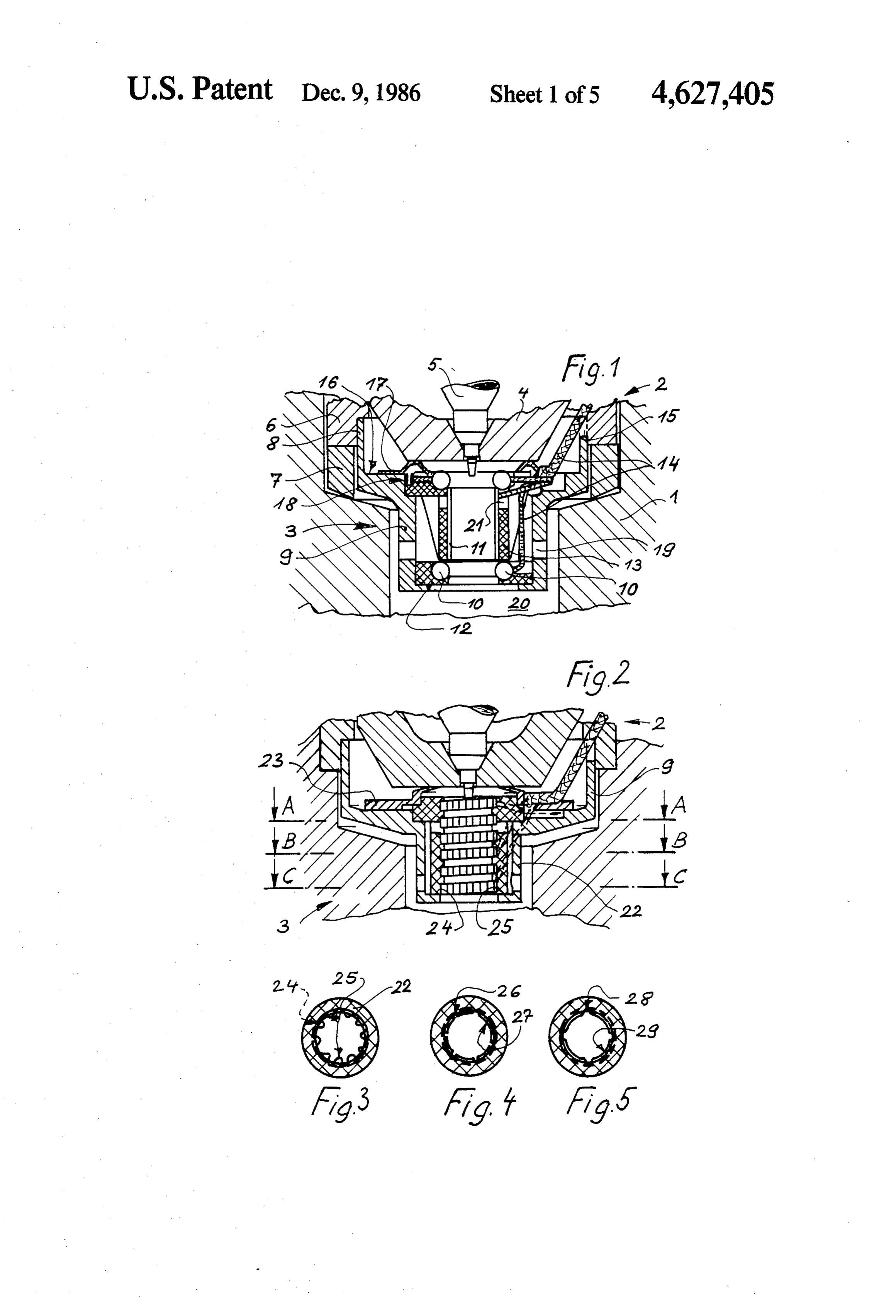
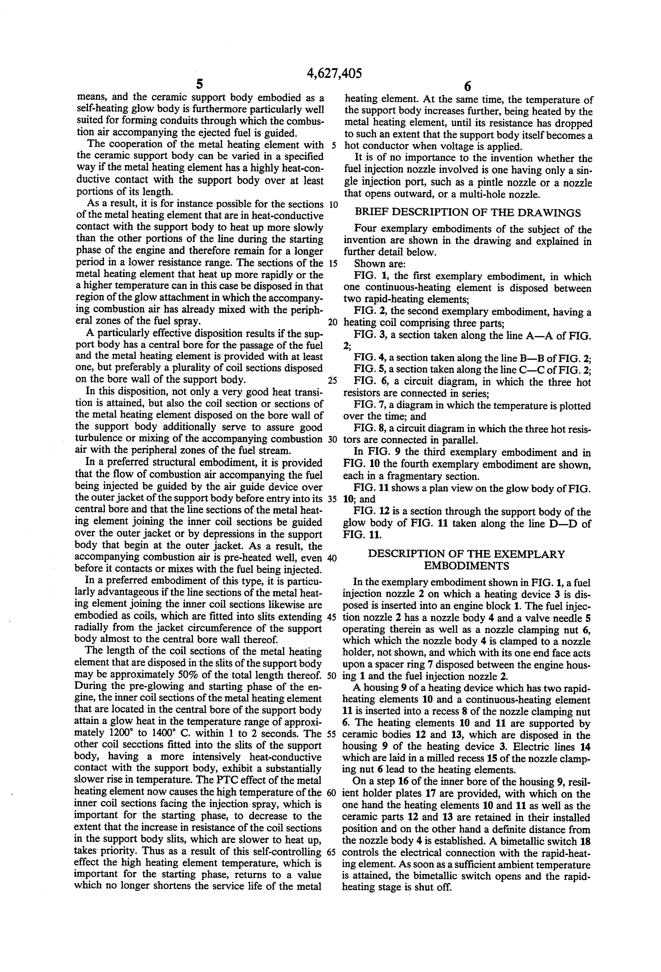
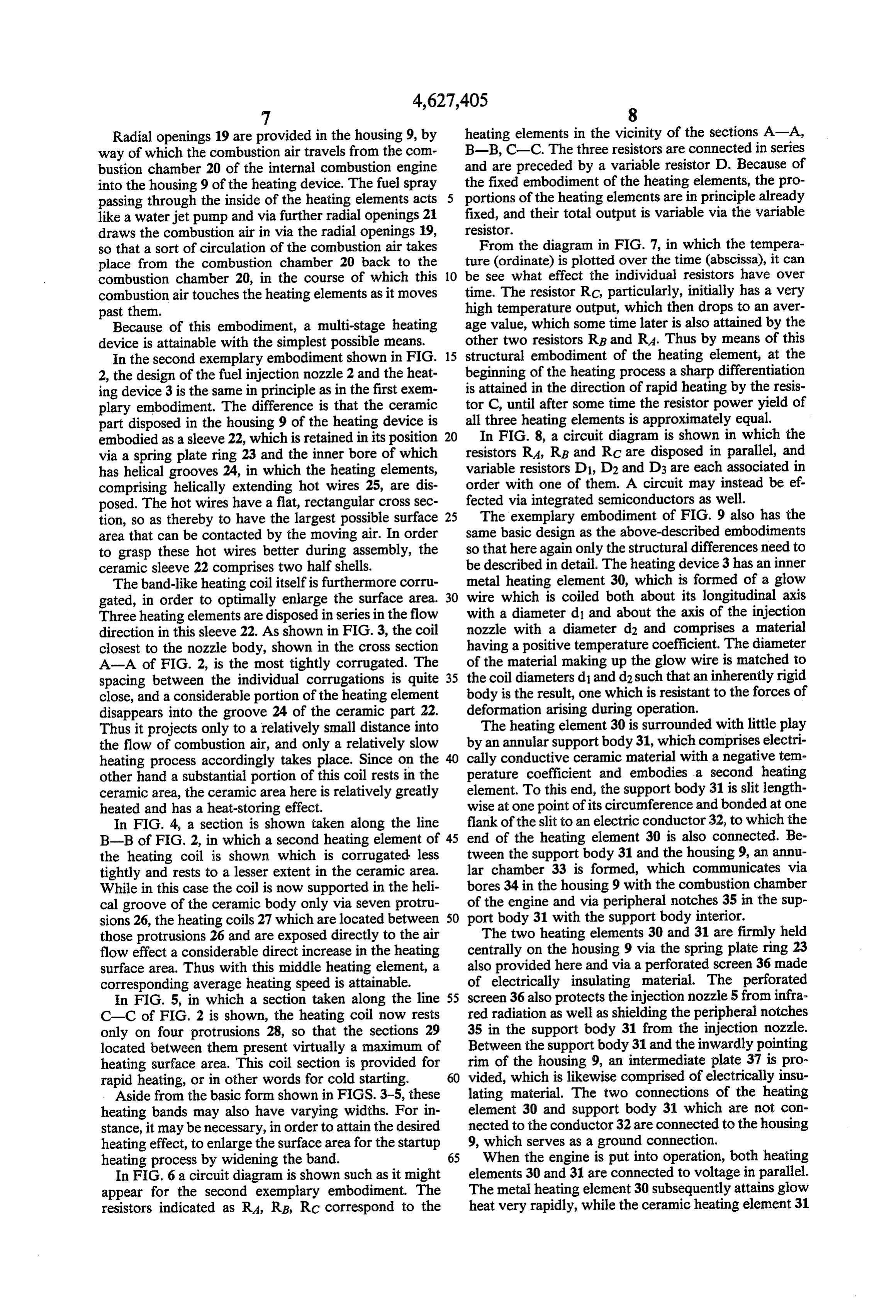
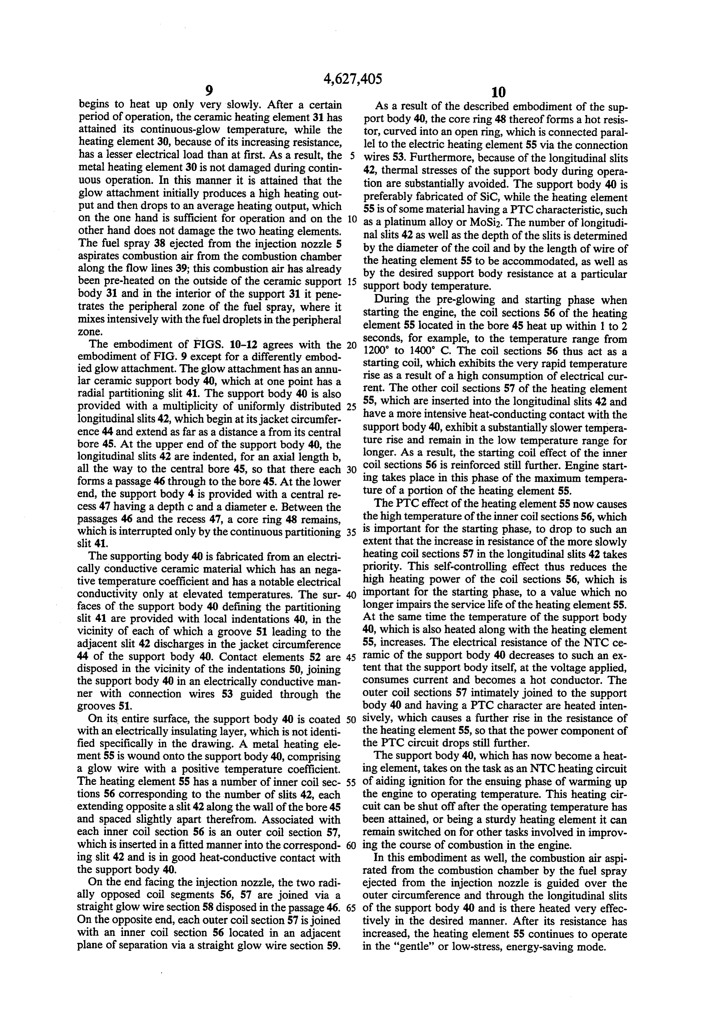
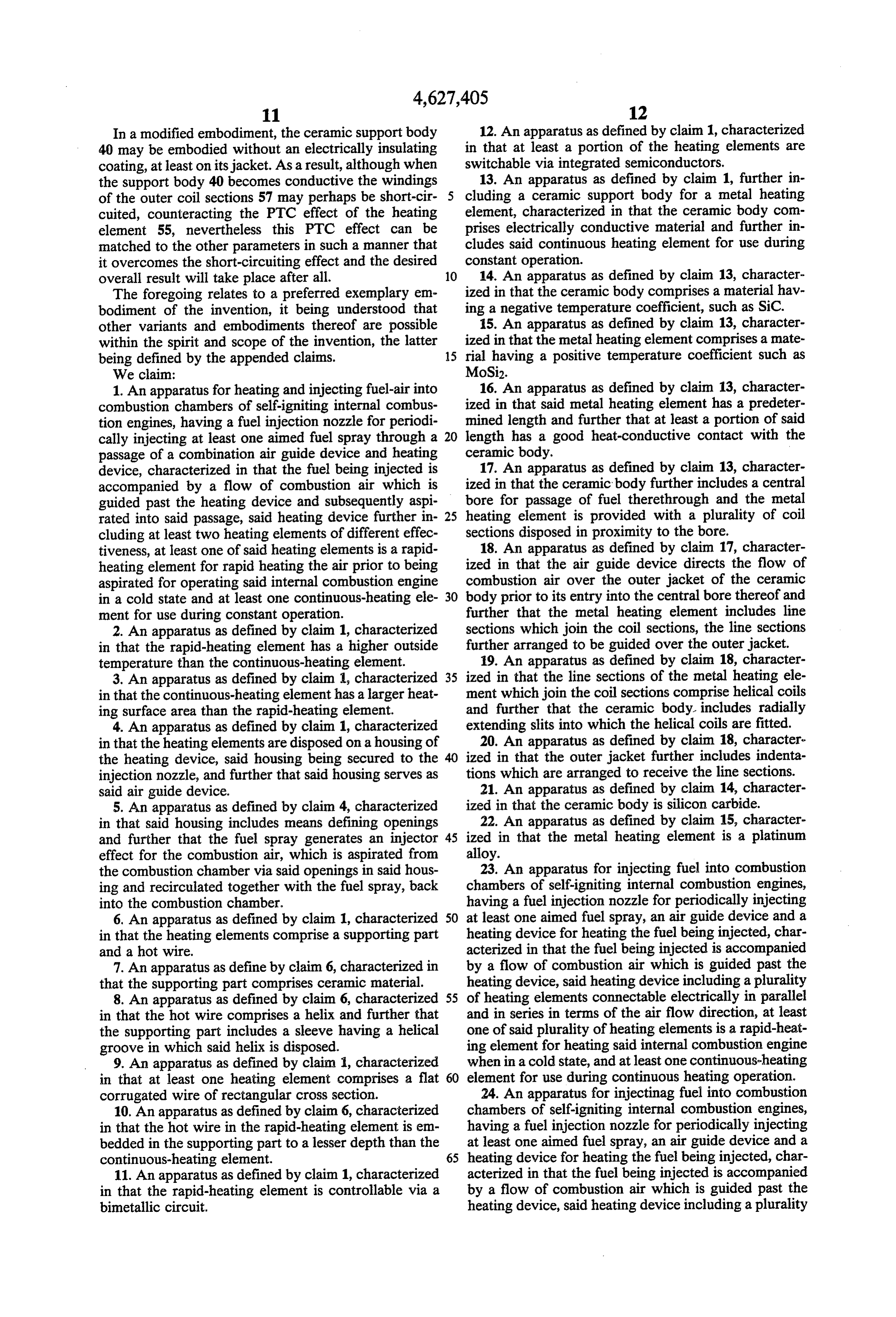
the ceramic support body can be varied in a specified It is of no importance to the invention whether the way if the metal heating element has a highly heat-con fuel injection nozzle involved is one having only a sin ductive contact with the support body over at least gle injection port, such as a pintle nozzle or a nozzle portions of its length. that opens outward, or a multi-hole nozzle. As a result, it is for instance possible for the sections 10 BRIEF DESCRIPTION OF THE DRAWINGS of the metal heating element that are in heat-conductive contact with the support body to heat up more slowly Four exemplary embodiments of the subject of the than the other portions of the line during the starting invention are shown in the drawing and explained in phase of the engine and therefore remain for a longer further detail below.
period in a lower resistance range. The sections of the 15 Shown are:
metal heating element that heat up more rapidly or the FIG. 1, the first exemplary embodiment, in which a higher temperature can in this case be disposed in that one continuous-heating element is disposed between region of the glow attachment in which the accompany two rapid-heating elements;
ing combustion air has already mixed with the periph FIG. 2, the second exemplary embodiment, having a eral zones of the fuel spray. 20 heating coil comprising three parts; A particularly effective disposition results if the sup FIG. 3, a section taken along the line A-A of FIG. port body has a central bore for the passage of the fuel 2;
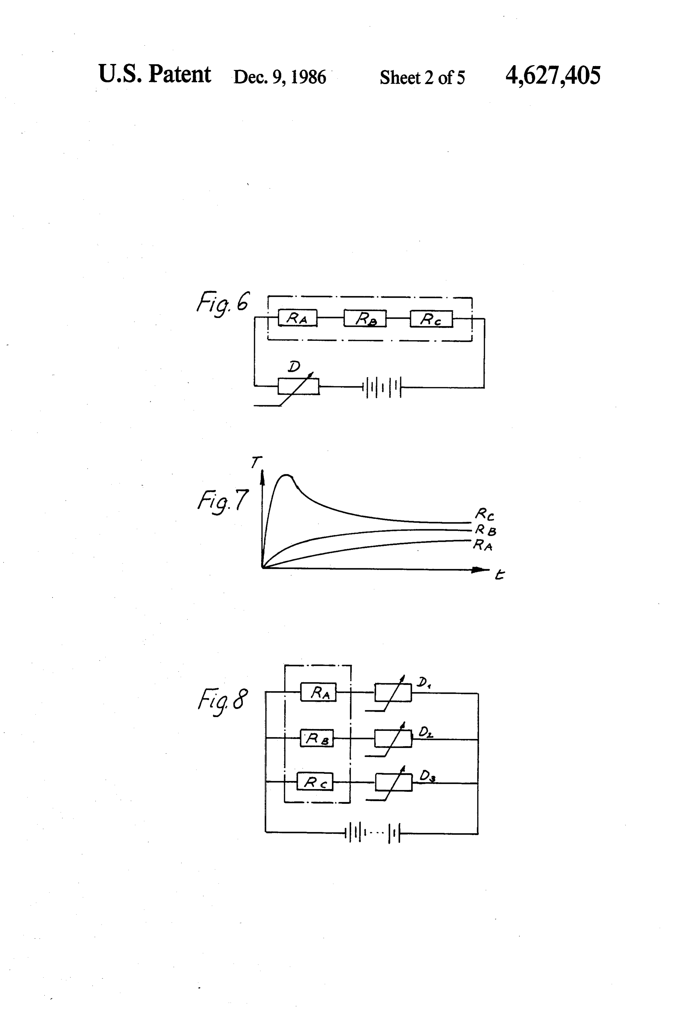
and the metal heating element is provided with at least FIG. 4, a section taken along the line B-B of FIG. 2; one, but preferably a plurality of coil sections disposed FIG. 5, a section taken along the line C-C of FIG. 2; on the bore wall of the support body. 25 FIG. 6, a circuit diagram, in which the three hot In this disposition, not only a very good heat transi resistors are connected in series;
tion is attained, but also the coil section or sections of FIG. 7, a diagram in which the temperature is plotted the metal heating element disposed on the bore wall of over the time; and the support body additionally serve to assure good FIG. 8, a circuit diagram in which the three hot resis turbulence or mixing of the accompanying combustion 30 tors are connected in parallel.
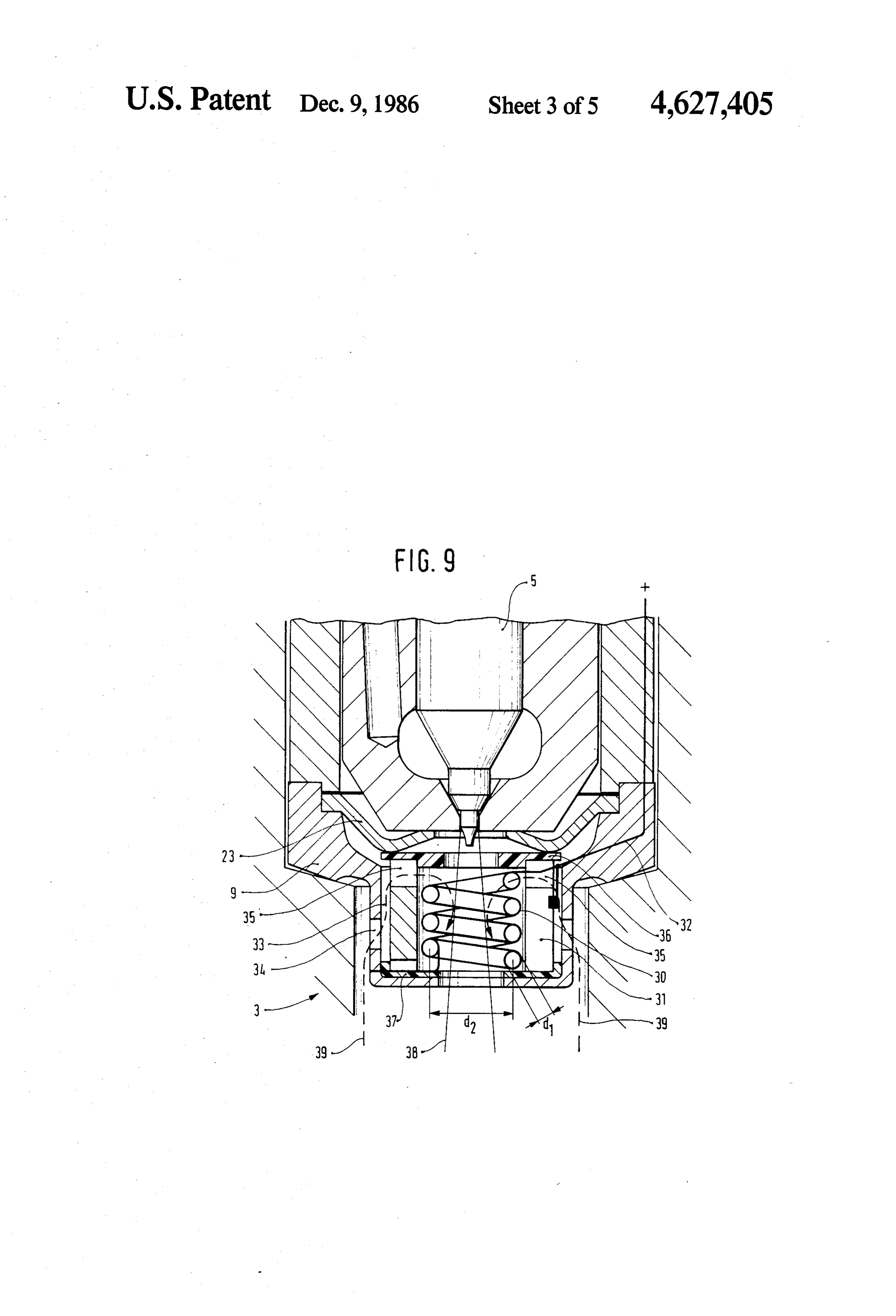
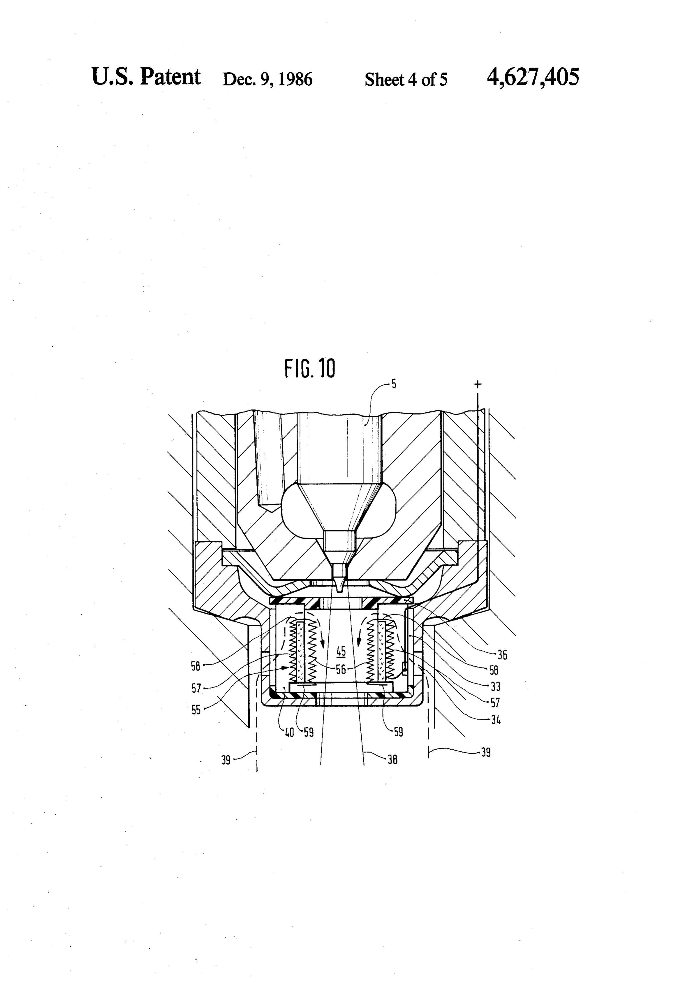
air with the peripheral zones of the fuel stream. In FIG. 9 the third exemplary embodiment and in In a preferred structural embodiment, it is provided FIG. 10 the fourth exemplary embodiment are shown, that the flow of combustion air accompanying the fuel each in a fragmentary section.
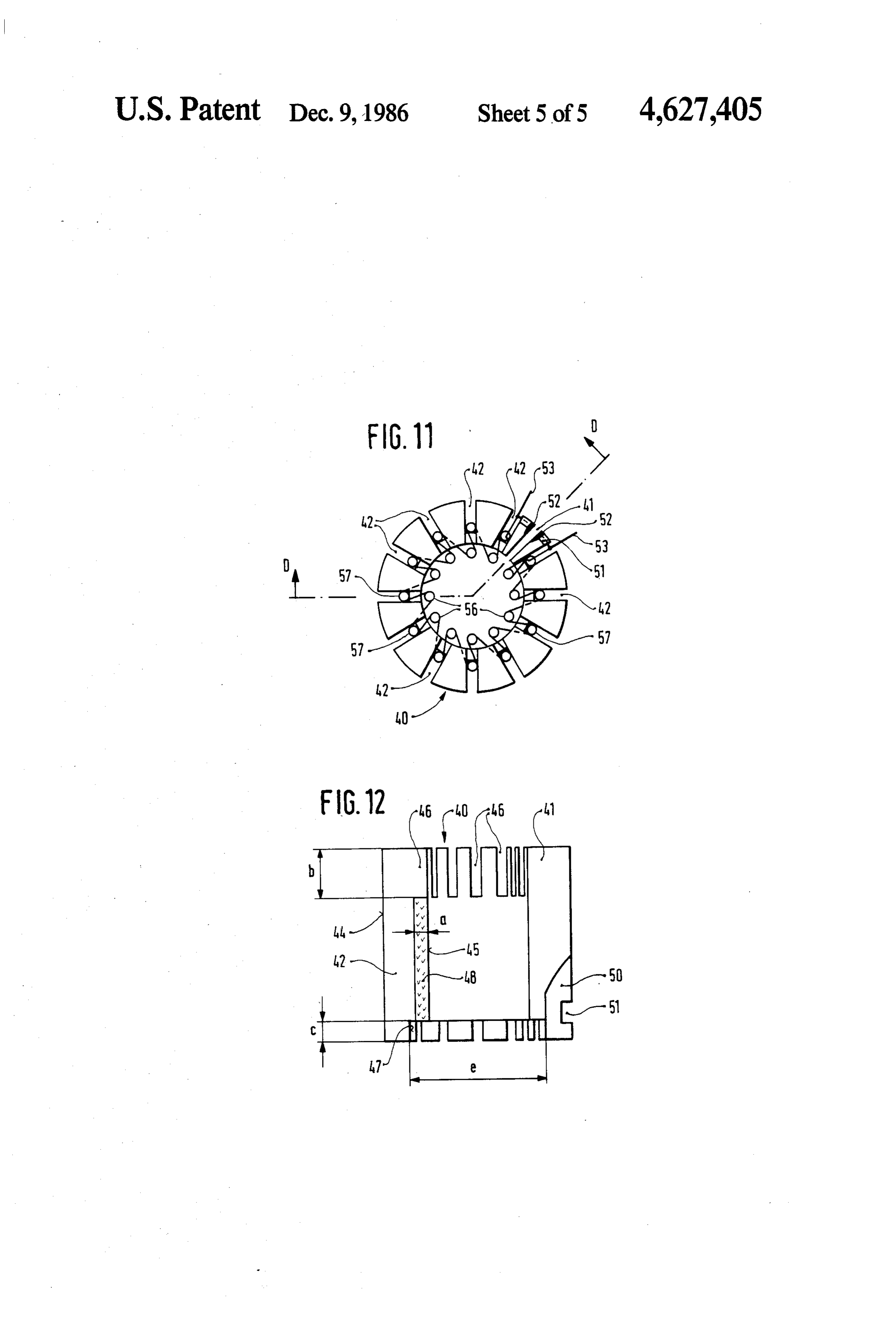
being injected be guided by the air guide device over FIG. 11 shows a plan view on the glow body of FIG. the outerjacket of the support body before entry into its 35 10; and central bore and that the line sections of the metal heat FIG. 12 is a section through the support body of the ing element joining the inner coil sections be guided glow body of FIG. 11 taken along the line D-D of over the outer jacket or by depressions in the support FIG. 11.
body that begin at the outer jacket. As a result, the accompanying combustion air is pre-heated well, even DESCRIPTION OF THE EXEMPLARY before it contacts or mixes with the fuel being injected. EMBODIMENTS In a preferred embodiment of this type, it is particu In the exemplary embodiment shown in FIG. 1, a fuel larly advantageous if the line sections of the metal heat injection nozzle 2 on which a heating device 3 is dis ing element joining the inner coil sections likewise are posed is inserted into an engine block 1. The fuel injec embodied as coils, which are fitted into slits extending 45 tion nozzle 2 has a nozzle body 4 and a valve needle 5 radially from the jacket circumference of the support operating therein as well as a nozzle clamping nut 6, body almost to the central bore wall thereof. which which the nozzle body 4 is clamped to a nozzle The length of the coil sections of the metal heating holder, not shown, and which with its one end face acts element that are disposed in the slits of the support body upon a spacer ring 7 disposed between the engine hous may be approximately 50% of the total length thereof. 50 ing 1 and the fuel injection nozzle 2. During the pre-glowing and starting phase of the en A housing 9 of a heating device which has two rapid gine, the inner coil sections of the metal heating element heating elements 10 and a continuous-heating element that are located in the central bore of the support body 11 is inserted into a recess 8 of the nozzle clamping nut attain a glow heat in the temperature range of approxi 6. The heating elements 10 and 11 are supported by mately 1200 to 1400° C. within 1 to 2 seconds. The 55 ceramic bodies 12 and 13, which are disposed in the other coil secctions fitted into the slits of the support housing 9 of the heating device 3. Electric lines 14 body, having a more intensively heat-conductive which are laid in a milled recess 15 of the nozzle clamp contact with the support body, exhibit a substantially ing nut 6 lead to the heating elements. slower rise in temperature. The PTC effect of the metal On a step 16 of the inner bore of the housing 9, resil heating element now causes the high temperature of the ient holder plates 17 are provided, with which on the inner coil sections facing the injection spray, which is one hand the heating elements 10 and 11 as well as the important for the starting phase, to decrease to the ceramic parts 12 and 13 are retained in their installed extent that the increase in resistance of the coil sections position and on the other hand a definite distance from in the support body slits, which are slower to heat up, the nozzle body 4 is established. A bimetallic switch 18 takes priority. Thus as a result of this self-controlling 65 controls the electrical connection with the rapid-heat effect the high heating element temperature, which is ing element. As soon as a sufficient ambient temperature important for the starting phase, returns to a value is attained, the bimetallic switch opens and the rapid which no longer shortens the service life of the metal heating stage is shut off.
Page 10
Radial openings 19 are provided in the housing 9, by heating elements in the vicinity of the sections A-A, way of which the combustion air travels from the com B-B, C-C. The three resistors are connected in series bustion chamber 20 of the internal combustion engine and are preceded by a variable resistor D. Because of into the housing 9 of the heating device. The fuel spray the fixed embodiment of the heating elements, the pro passing through the inside of the heating elements acts portions of the heating elements are in principle already like a water jet pump and via further radial openings 21 fixed, and their total output is variable via the variable draws the combustion air in via the radial openings 19, resistor.
so that a sort of circulation of the combustion air takes From the diagram in FIG. 7, in which the tempera place from the combustion chamber 20 back to the ture (ordinate) is plotted over the time (abscissa), it can combustion chamber 20, in the course of which this 10 be see what effect the individual resistors have over combustion air touches the heating elements as it moves time. The resistor RC, particularly, initially has a very past them. high temperature output, which then drops to an aver Because of this embodiment, a multi-stage heating age value, which some time later is also attained by the device is attainable with the simplest possible means. other two resistors RB and R4. Thus by means of this In the second exemplary embodiment shown in FIG. 15 structural embodiment of the heating element, at the 2, the design of the fuel injection nozzle 2 and the heat beginning of the heating process a sharp differentiation ing device 3 is the same in principle as in the first exem is attained in the direction of rapid heating by the resis plary embodiment. The difference is that the ceramic tor C, until after some time the resistor power yield of part disposed in the housing 9 of the heating device is all three heating elements is approximately equal. embodied as a sleeve 22, which is retained in its position 20 In FIG. 8, a circuit diagram is shown in which the via a spring plate ring 23 and the inner bore of which resistors RA, RB and RC are disposed in parallel, and has helical grooves 24, in which the heating elements, variable resistors D1, D2 and D3 are each associated in comprising helically extending hot wires 25, are dis order with one of them. A circuit may instead be ef posed. The hot wires have a flat, rectangular cross sec fected via integrated semiconductors as well. tion, so as thereby to have the largest possible surface 25 The exemplary embodiment of FIG. 9 also has the area that can be contacted by the moving air. In order same basic design as the above-described embodiments to grasp these hot wires better during assembly, the so that here again only the structural differences need to ceramic sleeve 22 comprises two half shells. be described in detail. The heating device 3 has an inner The band-like heating coil itself is furthermore corru metal heating element 30, which is formed of a glow gated, in order to optimally enlarge the surface area. 30 wire which is coiled both about its longitudinal axis Three heating elements are disposed in series in the flow with a diameter d1 and about the axis of the injection direction in this sleeve 22. As shown in FIG. 3, the coil nozzle with a diameter d2 and comprises a material closest to the nozzle body, shown in the cross section having a positive temperature coefficient. The diameter A-A of FIG. 2, is the most tightly corrugated. The of the material making up the glow wire is matched to spacing between the individual corrugations is quite 35 the coil diameters d and d2 such that an inherently rigid close, and a considerable portion of the heating element body is the result, one which is resistant to the forces of disappears into the groove 24 of the ceramic part 22. deformation arising during operation. Thus it projects only to a relatively small distance into The heating element 30 is surrounded with little play the flow of combustion air, and only a relatively slow by an annular support body 31, which comprises electri heating process accordingly takes place. Since on the cally conductive ceramic material with a negative tem other hand a substantial portion of this coil rests in the perature coefficient and embodies a second heating ceramic area, the ceramic area here is relatively greatly element. To this end, the support body 31 is slit length heated and has a heat-storing effect. wise at one point of its circumference and bonded at one In FIG. 4, a section is shown taken along the line flank of the slit to an electric conductor 32, to which the B-B of FIG. 2, in which a second heating element of 45 end of the heating element 30 is also connected. Be the heating coil is shown which is corrugated less tween the support body 31 and the housing 9, an annu tightly and rests to a lesser extent in the ceramic area. lar chamber 33 is formed, which communicates via While in this case the coil is now supported in the heli bores 34 in the housing 9 with the combustion chamber cal groove of the ceramic body only via seven protru of the engine and via peripheral notches 35 in the sup sions 26, the heating coils 27 which are located between 50 port body 31 with the support body interior. those protrusions 26 and are exposed directly to the air The two heating elements 30 and 31 are firmly held flow effect a considerable direct increase in the heating centrally on the housing 9 via the spring plate ring 23 surface area. Thus with this middle heating element, a also provided here and via a perforated screen 36 made corresponding average heating speed is attainable. of electrically insulating material. The perforated In FIG. 5, in which a section taken along the line 55 screen 36 also protects the injection nozzle 5 from infra C-C of FIG. 2 is shown, the heating coil now rests red radiation as well as shielding the peripheral notches only on four protrusions 28, so that the sections 29 35 in the support body 31 from the injection nozzle. located between them present virtually a maximum of Between the support body 31 and the inwardly pointing heating surface area. This coil section is provided for rim of the housing 9, an intermediate plate 37 is pro rapid heating, or in other words for cold starting. 60 vided, which is likewise comprised of electrically insu Aside from the basic form shown in FIGS. 3-5, these lating material. The two connections of the heating heating bands may also have varying widths. For in element 30 and support body 31 which are not con stance, it may be necessary, in order to attain the desired nected to the conductor 32 are connected to the housing heating effect, to enlarge the surface area for the startup 9, which serves as a ground connection. heating process by widening the band. 65 When the engine is put into operation, both heating In FIG. 6 a circuit diagram is shown such as it might elements 30 and 31 are connected to voltage in parallel. appear for the second exemplary embodiment. The The metal heating element 30 subsequently attains glow resistors indicated as RA, RB, RC correspond to the heat very rapidly, while the ceramic heating element 31
Page 11
begins to heat up only very slowly. After a certain As a result of the described embodiment of the sup period of operation, the ceramic heating element 31 has port body 40, the core ring 48 thereof forms a hot resis attained its continuous-glow temperature, while the tor, curved into an open ring, which is connected paral heating element 30, because of its increasing resistance, lel to the electric heating element 55 via the connection has a lesser electrical load than at first. As a result, the wires 53. Furthermore, because of the longitudinal slits metal heating element 30 is not damaged during contin 42, thermal stresses of the support body during opera uous operation. In this manner it is attained that the tion are substantially avoided. The support body 40 is glow attachment initially produces a high heating out preferably fabricated of SiC, while the heating element put and then drops to an average heating output, which 55 is of some material having a PTC characteristic, such on the one hand is sufficient for operation and on the 10 as a platinum alloy or MoSi2. The number of longitudi other hand does not damage the two heating elements. nal slits 42 as well as the depth of the slits is determined The fuel spray 38 ejected from the injection nozzle 5 by aspirates combustion air from the combustion chamber thethe diameter of the coil and by the length of wire of heating element 55 to be accommodated, as well as along the flow lines 39; this combustion air has already by the desired support body resistance at a particular been pre-heated on the outside of the ceramic support 15 support body temperature.
body 31 and in the interior of the support 31 it pene During the pre-glowing and starting phase when trates the peripheral zone of the fuel spray, where it starting the engine, the coil sections 56 of the heating mixes intensively with the fuel droplets in the peripheral element 55 located in the bore 45 heat up within 1 to 2
The embodiment of FIGS. 10-12 agrees with the 20 seconds, for example, to the temperature range from 1200' to 1400° C. The coil sections 56 thus act as a embodiment of FIG. 9 except for a differently embod starting coil, which exhibits the very rapid temperature ied glow attachment. The glow attachment has an annu rise lar ceramic support body 40, which at one point has a rent.asThe a result of a high consumption of electrical cur other coil sections 57 of the heating element radial partitioning slit 41. The support body 40 is also provided with a multiplicity of uniformly distributed 25 55, which are inserted into the longitudinal slits 42 and longitudinal slits 42, which begin at its jacket circumfer have a more intensive heat-conducting contact with the support body 40, exhibit a substantially slower tempera ence 44 and extend as far as a distance a from its central bore 45. At the upper end of the support body 40, the ture rise and remain in the low temperature range for longitudinal slits 42 are indented, for an axial length b, longer. As a result, the starting coil effect of the inner all the way to the central bore 45, so that there each 30 coil sections 56 is reinforced still further. Engine start forms a passage 46through to the bore 45. At the lower ing takes place in this phase of the maximum tempera end, the support body 4 is provided with a central re ture of a portion of the heating element 55. cess 47 having a depth c and a diameter e. Between the The PTC effect of the heating element 55 now causes passages 46 and the recess 47, a core ring 48 remains, the high temperature of the inner coil sections 56, which which is interrupted only by the continuous partitioning 35 is important for the starting phase, to drop to such an slit 41. extent that the increase in resistance of the more slowly The supporting body 40 is fabricated from an electri heating coil sections 57 in the longitudinal slits 42 takes cally conductive ceramic material which has an nega priority. This self-controlling effect thus reduces the tive temperature coefficient and has a notable electrical high heating power of the coil sections 56, which is conductivity only at elevated temperatures. The sur important for the starting phase, to a value which no faces of the support body 40 defining the partitioning longer impairs the service life of the heating element 55. slit 41 are provided with local indentations 40, in the At the same time the temperature of the support body vicinity of each of which a groove 51 leading to the 40, which is also heated along with the heating element adjacent slit 42 discharges in the jacket circumference 55, increases. The electrical resistance of the NTC ce 44 of the support body 40. Contact elements 52 are 45 ramic of the support body 40 decreases to such an ex disposed in the vicinity of the indentations 50, joining tent that the support body itself, at the voltage applied, the support body 40 in an electrically conductive man consumes current and becomes a hot conductor. The ner with connection wires 53 guided through the outer coil sections 57 intimately joined to the support grooves 51. body 40 and having a PTC character are heated inten On its entire surface, the support body 40 is coated 50 sively, which causes a further rise in the resistance of with an electrically insulating layer, which is not identi the heating element 55, so that the power component of fied specifically in the drawing. A metal heating ele the PTC circuit drops still further. ment 55 is wound onto the support body 40, comprising The support body 40, which has now become a heat a glow wire with a positive temperature coefficient. ing element, takes on the task as an NTC heating circuit The heating element 55 has a number of inner coil sec 55 of aiding ignition for the ensuing phase of warming up tions 56 corresponding to the number of slits 42, each the engine to operating temperature. This heating cir extending opposite a slit 42 along the wall of the bore 45 cuit can be shut off after the operating temperature has and spaced slightly apart therefrom. Associated with been attained, or being a sturdy heating element it can each inner coil section 56 is an outer coil section 57, remain switched on for other tasks involved in improv which is inserted in a fitted manner into the correspond ing the course of combustion in the engine. ing slit 42 and is in good heat-conductive contact with In this embodiment as well, the combustion air aspi the support body 40. rated from the combustion chamber by the fuel spray On the end facing the injection nozzle, the two radi ejected from the injection nozzle is guided over the ally opposed coil segments 56, 57 are joined via a outer circumference and through the longitudinal slits straight glow wire section 58 disposed in the passage 46. 65 of the support body 40 and is there heated very effec On the opposite end, each outer coil section 57 is joined tively in the desired manner. After its resistance has with an inner coil section 56 located in an adjacent increased, the heating element 55 continues to operate plane of separation via a straight glow wire section 59. in the "gentle' or low-stress, energy-saving mode.
Page 12
In a modified embodiment, the ceramic support body 12. An apparatus as defined by claim 1, characterized 40 may be embodied without an electrically insulating in that at least a portion of the heating elements are coating, at least on its jacket. As a result, although when switchable via integrated semiconductors. the support body 40 becomes conductive the windings 13. An apparatus as defined by claim 1, further in of the outer coil sections 57 may perhaps be short-cir cluding a ceramic support body for a metal heating cuited, counteracting the PTC effect of the heating element, characterized in that the ceramic body com element 55, nevertheless this PTC effect can be prises electrically conductive material and further in matched to the other parameters in such a manner that cludes said continuous heating element for use during it overcomes the short-circuiting effect and the desired constant operation.
overall result will take place after all. 10 14. An apparatus as defined by claim 13, character The foregoing relates to a preferred exemplary em ized in that the ceramic body comprises a material hav bodiment of the invention, it being understood that ing a negative temperature coefficient, such as SiC. other variants and embodiments thereof are possible 15. An apparatus as defined by claim 13, character within the spirit and scope of the invention, the latter ized in that the metal heating element comprises a mate being defined by the appended claims. 15 rial having a positive temperature coefficient such as We claim: MoSi2.
1. An apparatus for heating and injecting fuel-air into 16. An apparatus as defined by claim 13, character combustion chambers of self-igniting internal combus ized in that said metal heating element has a predeter tion engines, having a fuel injection nozzle for periodi mined length and further that at least a portion of said cally injecting at least one aimed fuel spray through a 20 length has a good heat-conductive contact with the passage of a combination air guide device and heating ceramic body.
device, characterized in that the fuel being injected is 17. An apparatus as defined by claim 13, character accompanied by a flow of combustion air which is ized in that the ceramic body further includes a central guided past the heating device and subsequently aspi bore for passage of fuel therethrough and the metal rated into said passage, said heating device further in 25 heating element is provided with a plurality of coil cluding at least two heating elements of different effec sections disposed in proximity to the bore. tiveness, at least one of said heating elements is a rapid 18. An apparatus as defined by claim 17, character heating element for rapid heating the air prior to being ized in that the air guide device directs the flow of aspirated for operating said internal combustion engine combustion air over the outer jacket of the ceramic in a cold state and at least one continuous-heating ele 30 body prior to its entry into the central bore thereof and ment for use during constant operation. further that the metal heating element includes line 2. An apparatus as defined by claim 1, characterized sections which join the coil sections, the line sections in that the rapid-heating element has a higher outside further arranged to be guided over the outer jacket. temperature than the continuous-heating element. 19. An apparatus as defined by claim 18, character 3. An apparatus as defined by claim 1, characterized 35 ized in that the line sections of the metal heating ele in that the continuous-heating element has a larger heat ment which join the coil sections comprise helical coils ing surface area than the rapid-heating element. and further that the ceramic body includes radially 4. An apparatus as defined by claim 1, characterized extending slits into which the helical coils are fitted. in that the heating elements are disposed on a housing of 20. An apparatus as defined by claim 18, character the heating device, said housing being secured to the 40 ized in that the outer jacket further includes indenta injection nozzle, and further that said housing serves as tions which are arranged to receive the line sections. said air guide device. 21. An apparatus as defined by claim 14, character 5. An apparatus as defined by claim 4, characterized ized in that the ceramic body is silicon carbide. in that said housing includes means defining openings 22. An apparatus as defined by claim 15, character and further that the fuel spray generates an injector 45 ized in that the metal heating element is a platinum effect for the combustion air, which is aspirated from alloy.
the combustion chamber via said openings in said hous 23. An apparatus for injecting fuel into combustion ing and recirculated together with the fuel spray, back chambers of self-igniting internal combustion engines, into the combustion chamber. having a fuel injection nozzle for periodically injecting 6. An apparatus as defined by claim 1, characterized 50 at least one aimed fuel spray, an air guide device and a in that the heating elements comprise a supporting part heating device for heating the fuel being injected, char and a hot wire. acterized in that the fuel being injected is accompanied 7. An apparatus as define by claim 6, characterized in by a flow of combustion air which is guided past the that the supporting part comprises ceramic material. heating device, said heating device including a plurality 8. An apparatus as defined by claim 6, characterized 55 of heating elements connectable electrically in parallel in that the hot wire comprises a helix and further that and in series in terms of the air flow direction, at least the supporting part includes a sleeve having a helical one of said plurality of heating elements is a rapid-heat groove in which said helix is disposed. ing element for heating said internal combustion engine 9. An apparatus as defined by claim i, characterized when in a cold state, and at least one continuous-heating in that at least one heating element comprises a flat 60 element for use during continuous heating operation. corrugated wire of rectangular cross section. 24. An apparatus for injectinag fuel into combustion 10. An apparatus as defined by claim 6, characterized chambers of self-igniting internal combustion engines, in that the hot wire in the rapid-heating element is em having a fuel injection nozzle for periodically injecting bedded in the supporting part to a lesser depth than the at least one aimed fuel spray, an air guide device and a continuous-heating element. 65 heating device for heating the fuel being injected, char 11. An apparatus as defined by claim 1, characterized acterized in that the fuel being injected is accompanied in that the rapid-heating element is controllable via a by a flow of combustion air which is guided past the bimetallic circuit. heating device, said heating device including a plurality
Page 13
of heating elements at least one of said plurality of heat- ous heating operation and said plurality of heating ele ing elements is a rapid heating element for heating said ments are connectable in series electrically and in series internal combustion engine when in a cold state, at least in terms of the air flow direction. one continuous heating element for use during continu- sk k is sk
Provenance
- Collection
- Cited prior art
- Original PDF
- patentimages.storage.googleapis.com →
- Filed
- 1984-03-30
- Pages
- 13
- Method
- pdftotext (the PDF's own text layer) + pdftoppm 300dpi page scans
- Source
- Google Patents bibliographic record
- Granted
- 1986-12-09
- Inventors
- Ernst Imhof; Iwan Komaroff; Gunther Schmid; Werner Grunwald; Helmut Reum; Robert Bosch GmbH
- Transcribed from
- patentimages.storage.googleapis.com →