patent · US4365618
Heliostatic solar energy conversion system
28 December 1982
Page 1 — bibliographic record
United States Patent (19) (11) 4,365,618 Jones 45) Dec. 28, 1982 (54) HELIOSTATIC SOLAR ENERGY OTHER PUBLICATIONS
CONVERSON SYSTEM
"The Rise of Control Receivers' by A. C. Skinrod-p.
(76) Inventor: Dedger Jones, 3451 Stonehaven Ct., 84-Solar Age-Aug. 1980. South, Columbus, Ohio 43220 "A Novel Design for a Solar Concentrating System'. A Thesis by Thomas Alan Pettenski-Ohio State Univ (21) Appl. No.: 213,210 -1980.
Primary Examiner-Samuel Scott 22) Filed: Dec. 5, 1980 Assistant Examiner-G. Anderson Attorney, Agent, or Firm-Robert B. Watkins (51) Int. Cl. ......................... F24J 3/02; A63G 21/00 (52) U.S. Cl. .................................... 126/425; 126/438; (57) ABSTRACT 104/135 A heliostatic solar energy conversion system in which a 58 Field of Search ....................... 126/424, 425, 438; plurality of multi-faceted heliostats are supported on 104/135; 353/3; 250/203 R one or more platforms that move in a segment of a circular path about a central receiver as a center. The 56) References Cited heliostats are mounted in frames that pivot on the plat
the platforms are supported in a concave spherical de 811,274 1/1906 Carter ................................. 126/424 pression in the ground. The heliostats of the invention 1,386,781 8/1921 Harvey . are constructed with a plurality of intersecting beams 3,884,217 5/1975 Wartes ................................ 126/270 and stringers, and the stringers are formed with para 3,905,352 9/1975 Jahn .................................... 126/270 bolic flanges which support the facets so that the angle 3,977,773 8/1976 Hubbard ............................. 126/425 of incidence between the sun and the focal point of the 4,266,530 5/1981 Steadman ................................ 74/56 central receiver is generally in the center of each facet. FOREIGN PATENT DOCUMENTS A vernier adjustment is provided for each heliostat. 2356095 6/1976 France ................................ 126/437 9 Claims, 14 Drawing Figures
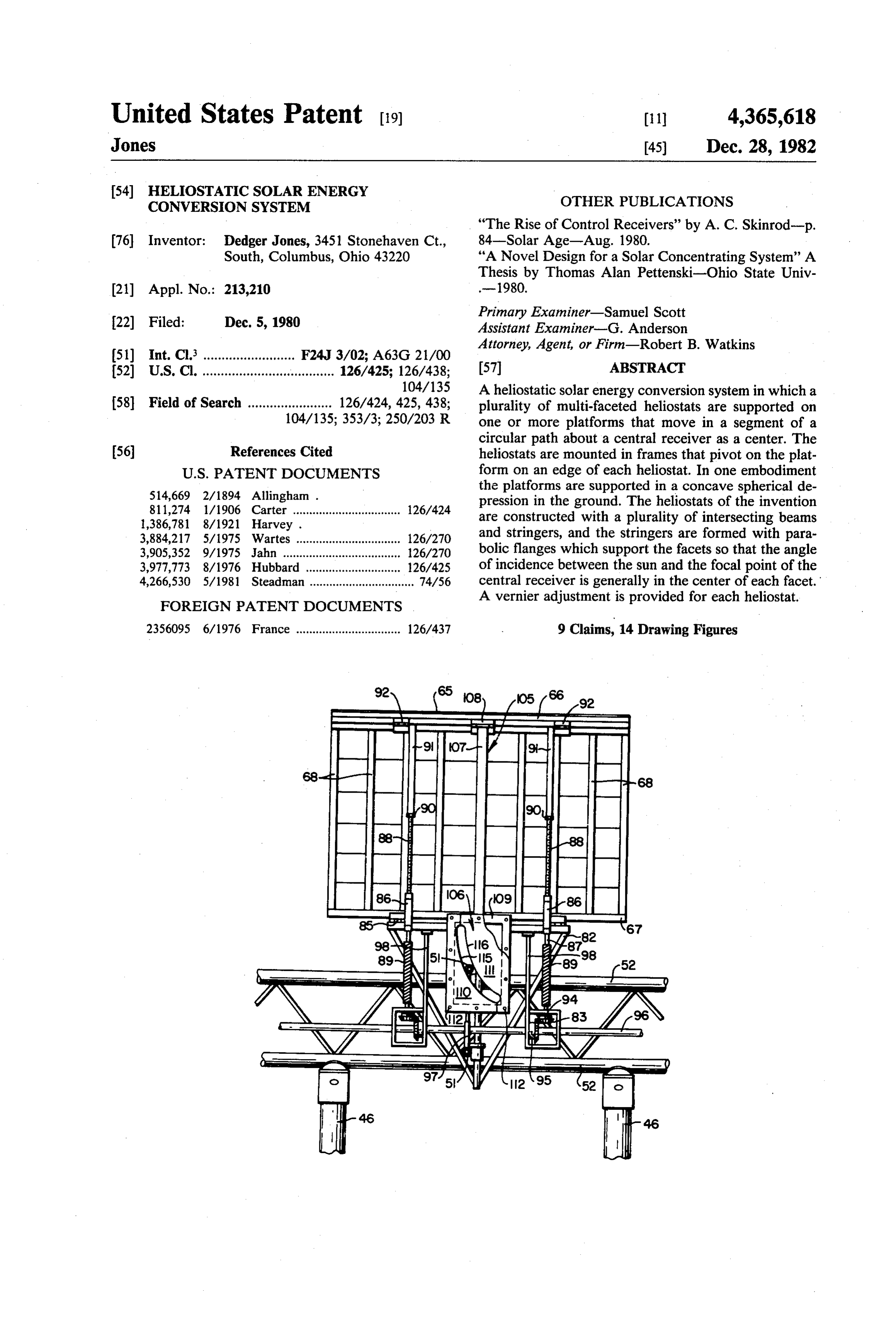
Page 2
AUXLARY POWER
HEOSAIC COLLECOR FIELD RCVER SUBSYSTEM ELECRC POWER
RANSMSSON
RECEIVER
REGULATION
HEAT
REECTION
ELECTRICAL POWER
GENERAON SUBSYSTEM
THERMAL
STORAGE SUBSYSTEM
AMOSPERE
REFRACON
FACES
CENTRAL
RECEIVER
TOWER
SUNS RAYS
HELOSTATS
REFLECTOR
NYaN. Y. NNY
2 lazs NYS anan an N
Page 3
Drawing sheet — no readable text.
Page 4
Drawing sheet — no readable text.
Page 5
Drawing sheet — no readable text.
Page 6
Drawing sheet — no readable text.
Page 7
Drawing sheet — no readable text.
Page 8
Drawing sheet — no readable text.
Page 9
Drawing sheet — no readable text.
Page 10
Drawing sheet — no readable text.
Page 11
tion of this invention is to provide an economical helio
HELOSTATIC SOLAR ENERGY CONVERSION stat construction.
SYSTEM Almost all central receiver power plants can be clas sified as solar thermal conversion (STC) systems. These
SUMMARY OF THE INVENTION systems collect solar radiation and convert it to thermal This invention relates to a heliostatic solar energy energy and ultimately electric power. The heat is trans conversion system and more particularly to one of the ferred to a working fluid for use in a solar thermal elec central receiver solar power plant type. The invention tric conversion system primarily to generate electricity. also relates to various heliostat construction features O Solar thermal electric energy systems utilize a high and focusing means. temperature thermo dynamic cycle to convert solar Briefly and in summary, the invention is a solar en energy to electrical energy with maximum efficiency. ergy conversion system which includes a field of helio temperatureisasrejected
Waste heat to the environment at as low a practical.
stats having a plurality of reflective facets, such as mir In a solar total energy system, solar energy is used to rors, and a central receiver which is positioned a se 15 generate electricity also, but under a constraint that the lected distance apart from the heliostat, forming a se rejected heat lected angle of incidence at the center of each facet space heating,is water to be at a high temperature suitable for heating, operation of absorption between the rays of the sun and the central receiver. It air conditioning, or commercial processes. Although comprises one or more platforms supporting a plurality the generation of electricity is delibrately less efficient of frames with each frame having edges and supporting 20 a total energy system, the overall efficiency of utiliza a plurality of the reflecting facets which in combination in are in fixed position to comprise a heliostat, with each tionTheof primary the collected solar radiation is much greater.
limitation to wide spread implementa platform being constructed for movement in a substan tion of both kinds of solar thermal systems in the past tially circular path in the horizontal plane about the central receiver as a center, and with each frame being 25 has stemmed from the relatively high cost estimated for solar power systems as compared to the cost of utilizing pivotally supported on the platform on a axis coincident fossil or nuclear fuels. Advanced concepts, new materi with one edge of each frame. als and innovative engineering of systems indicate that In an important embodiment of the invention the energy costs in the future for solar thermal conversion platform or platforms rotate about the central receiver systems can be competitive with fossil fuel sources. . in a semi-spherical concave depression in the ground 30 The construction and testing of central receiver solar providing significant economies in the construction of power. plants is a rapidly growing and ever changing central receiver solar power plants. technological endeavor. Only a few test facilities are Another important feature of the invention is embod constructed and operating. Existing facilities range ied in the construction of the heliostat frame which is from the French M-1 solar furnace in Odeillo, France, pivotally supported at one edge and comprises inter 35 to the solar total energy large scale experiment at Shen secting beams and stringers, with the stringers having a andoah, Ga., which is set up to provide both electrical parabolic contoured flange on which are fastened facets power and thermal energy for processed steam heating or mirrors. and air conditioning requirements. At Sandia lab in Still another feature of the invention is the construc Albuquerque, N. Mex., a computer controlled helio tion providing for a vernier adjustment in the azmuthal 40 static system is in operation.
position of each heliostat by cam means operable to The intent of this invention is to provide a novel rotate the heliostat about a vertical axis when the helio heliostatic solar energy conversion system that will cost stat is rotated about the horizontal axis. considerably less to produce, set up, and maintain. The The world is facing an energy crisis. Rising costs and field of heliostats will employ readily obtainable stock predicted shortages of conventional energy resources 45 materials and simple, common manufacturing pro have renewed interest in the development of alternative CSS.S.
forms of energy. Indications are that one of these forms, Solar thermal electric power plants can usually be solar energy, will have an impact on the world's future classified as two types, central receiver and distributive energy needs. Obvious difficulties in the use of solar collection systems. In the central receiver system, a energy include the diurnal and seasonal cycles, the un 50 large field of reflecting mirrors (heliostats) are used to predictable effects of the weather, the nonstorability of concentrate energy on a tower-mounted receiver. In the the energy in its primary form, and the low-power den distributive collection systems, the thermal energy is sity of the direct radiation. This invention is directed to concentrated at a large number of disbursing stations overcoming some of these difficulties. throughout the collecting field which then can be com The bulk of solar thermal mechanical systems are of 55 bined and transported to a central location. the central receiver solar power plant type. Central Because the central receiver system focuses all of the receiver systems are capable of providing block power incoming direct solar radiation on a single point, tem in the range of one to several hundred megawatts per peratures upwards of 1,000 F. (540 C.) are obtainable. plant. A solar thermal power plant has 5 major subsys The collector/concentrator/reflector subsystem inher tems. These are the optical collector plant concentrator 60 ent in all central receiver systems consists of a field of (often a heliostat), the receiver and heat transfer ele heliostats and a tracking control system to maintain ments, the prime mover/electrical generator, thermal continuous focus on the tower-mounted central re storage and a backup generation unit. Many central ceiver. The heliostats must track the sun in two dimen receiver solar power plants use a number of two axis sions; this is, one dimension tracks the altitudinal motion tracking mirrors or heliostats to redirect and focus sun 65 of the sun while the other dimension is concerned with light onto an absorber for the production of a heated the azimuthal motion of the sun. The altitudinal motion working fluid. The heliostats constitute the largest ex of the sun varies according to the time of day and time pense in a central receiver solar power plant. A motiva of the year. The aximuthal motion of the sun varies both
Page 12
with time of day and the time of the year, but primarily low maintenance. The optical behavior of the reflecting with the time of the day, making one arc of approxi heliostats is influenced by many factors, some predict mately 180 each day. able, like mirror reflectivity, slant range (distance from One large scale example of prior art is the CNRS the center of the heliostat to the center of the receiver) 1,000 KW Solar Furnace at Odeillo, France, which will and facet configuration. Other factors are of the non be described in further detail later. This unit employs a predictable type, such as sun tracking errors, surface field of 63 heliostats each of which is 6x7.5 M. The slope errors and intermittent wind loading. heliostats follow the sun and reflect its rays onto a para Sunlight impinges on a heliostat facet surface in a bolic reflector that concentrates 1 megawatt (MW) of diverging beam in such a way that the incoming cone thermal energy into an area of about 40 cm (16 inches) O has an apex angle of about 0.01 radians. This is deter in diameter at the focal point. In this area the heat flux mined by and is due to the size of the sun disk which is 1600W per cm2 and temperatures as high as 4100 K. varies slightly throughout the year. The cone is further are obtained. widened by atmospheric scattering, especially during Economic utilization of solar energy requires that the hazy, atmospheric conditions. Upon reflection from a energy be collected cheaply and used efficiently. The 15 facet surface the cone may be effectively broadened still heliostats in a heliostatic solar thermal electric energy more by the surface characteristics of the reflector facet power plant represent approximately 85% of the total and by the variations and vagueries of alignment behav cost of the system. Consequently, it has been important 1O.
in the past that they be nonuniformly distributed over Although the reflected sun shape cone coming from the field so that the shading and blocking of one helio 20 the surface of the reflector facet, would be unchanged, stat over another can be held to acceptable levels in in practice surface characteristics and surface alignment every region of the field over the course of a day and a uncertainties cause each reflected cone of rays to be year. On the other hand, heliostats must be spaced as subject to a distribution of directions called the error closely as possible to concentrate the energy in the cone. The average effective behavior of the reflected central receiver allowing the fixed cost of the central 25 rays is described by a second cone which is larger than receiver to be held within reasonable limits. the sun shaped cone. The concepts of an "error cone' Another constraint has been the receiver size. For a and "effective reflected cone' are useful in providing given receiver size the radius of the field is ultimately guidance in planning the measurement and analysis of limited by a boundary line beyond which the image size surface reflecting properties, surface slope error and of the receiver becomes so large that an unexceptable 30 heliostat alignment errors.
fraction of the energy redirected by a heliostat bypasses The further discussion of the prior art, and principles the receiver. The one MW thermal unit at Odeillo, of heliostatic use and construction will be found in the France, is an example of a system with a large and detailed description of the invention.
expensive central receiver. The heliostat field at the 5 For the reasons stated, there is strong emphasis being MW thermal central receiver test facility in Albuquer 35 given to the cost reduction of heliostats and heliostatic que, N. Mex. and the 10 MW electric California Edison solar thermal energy conversion systems. The Depart facility near Barstow, Calif., are examples of the large ment of Energy of the United States has established a spacing of heliostats required to prevent blocking and goal to achieve an installed cost of $100 per M2 (1978 shadowing. dollars) of reflector area by the year 1990. It is an object It is an object of this invention that heliostats in the 40 of this invention to meet this objective by features of field may be used more efficiently thus fewer are re this invention including reduction in the number of quired for necessary energy output. Another object is heliostats for a required energy output, or stated con that the heliostats may be more closely concentrated versely, higher reflection efficiency per heliostat over a together making possible a more closely confined focal given day or period of days.
point in the central receiver and therefore a less expen 45 In addition to reducing the number of heliostats and sive more efficient central receiver construction. increasing heliostat efficiency, it is an object of this In the large scale solar tower concept, the economic invention to provide novel heliostat construction in utilization of solar thermal energy is approached by which the ideal parabolic surface for the collection and using a field of low cost flat mirror heliostats to redirect concentration of the suns rays is simulated by an assem the solar energy to a central receiver. Geometric effects 50 bly of reflecting facets or mirrors which the facets are generally limit the diameter of the heliostat field to 3 to fixedly fastened to a frame made up of beams and string 5 times the tower height. Beyond this range the re ers making a composite series of anchor points for the flected image size becomes impractically large for effi facets which are on the surface of the parabola. Details cient collection at the receiver aperture. To prevent of the construction of the heliostat and its frame are adjacent mirrors from excessively blocking the light 55 important features of the invention. redirected toward the receiver, the mirrors must be Still another feature of the invention and an object is progressively sparsely distributed as the distance from to provide a novel manner of adjusting the attitude and the base of the tower increase. Studies have given opti azimuth of the heliostats in a field. mum heliostat coverage to ground coverage ratios The prior art reveals that many attempts have been ranging from 0.8 near the tower base to 0.2 in the north 60 made to find the optimum solution to the many prob ern corners (for a south facing field) with an average lems of efficiently using solar energy in a heliostatic ratio of 0.45. With this invention the average ratio re solar energy conversion system. U.S. Pat. Nos. mains near the optimum achievable at the center of the 3,892,433 and 3,905,352 are typical examples of these field (i.e. in line with the noonday azimuth). approaches.
Because the heliostats represent the major costs in the 65 Other objects and features of the invention will be installation of a central receiver system, they should be apparent and understood from the detailed description able to be massed produced, able to withstand extreme of the invention and the accompanying drawings which weather conditions, easily installed and give long life at follow.
Page 13
another heliostat or by some object to prevent it from
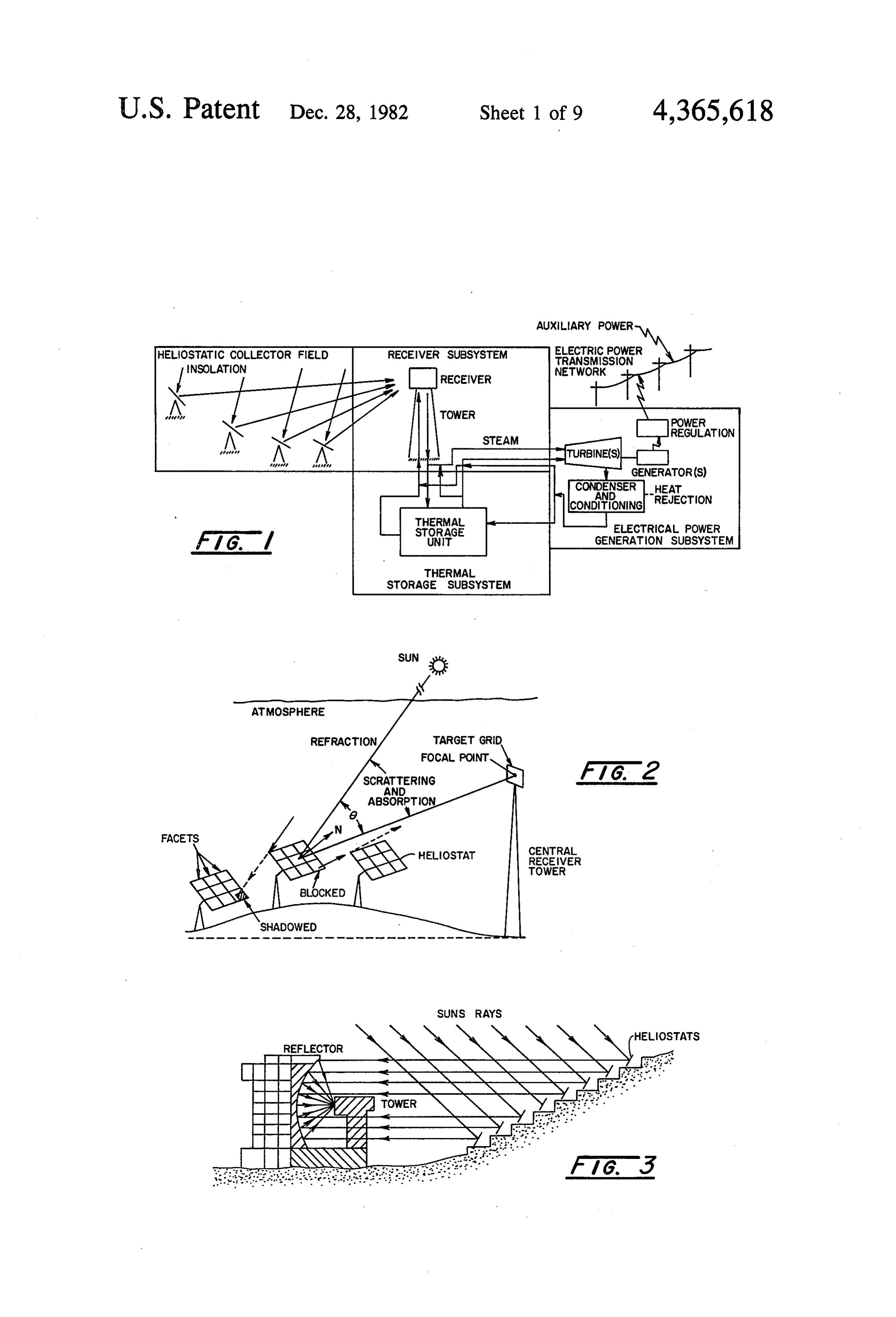
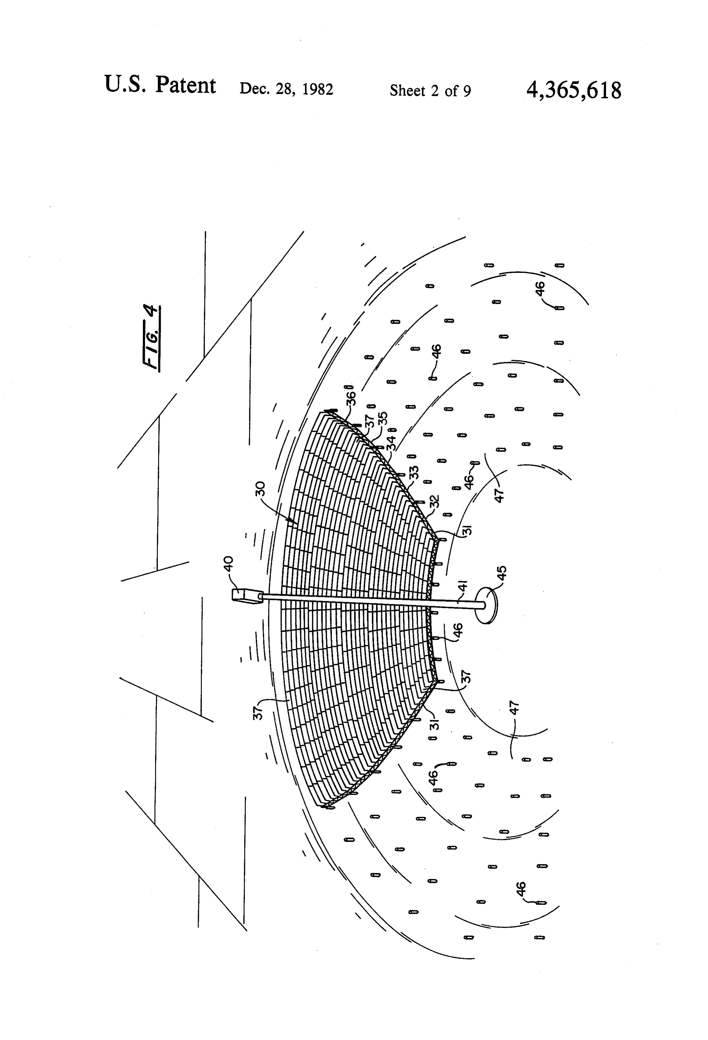
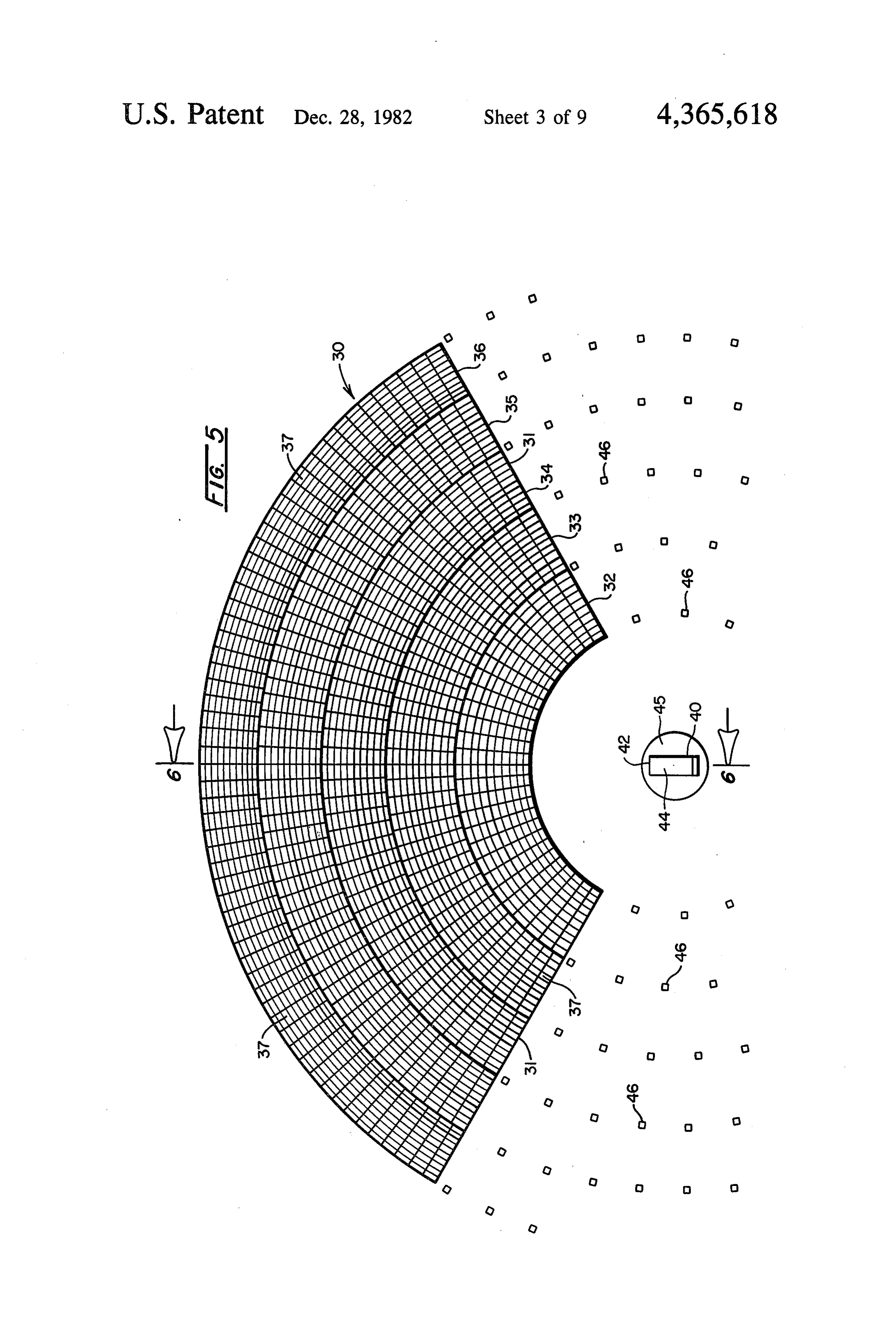
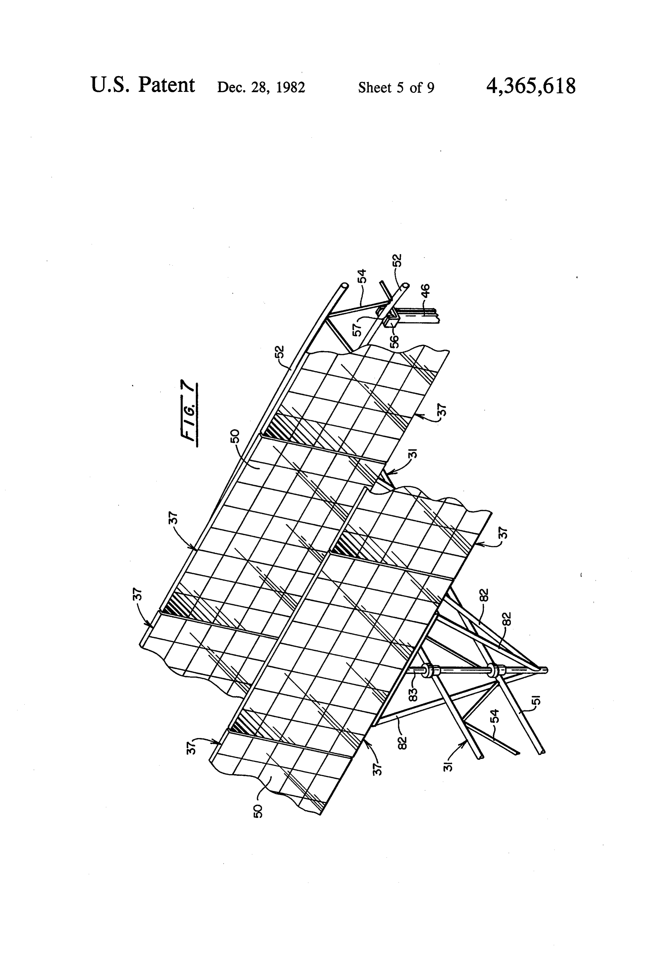
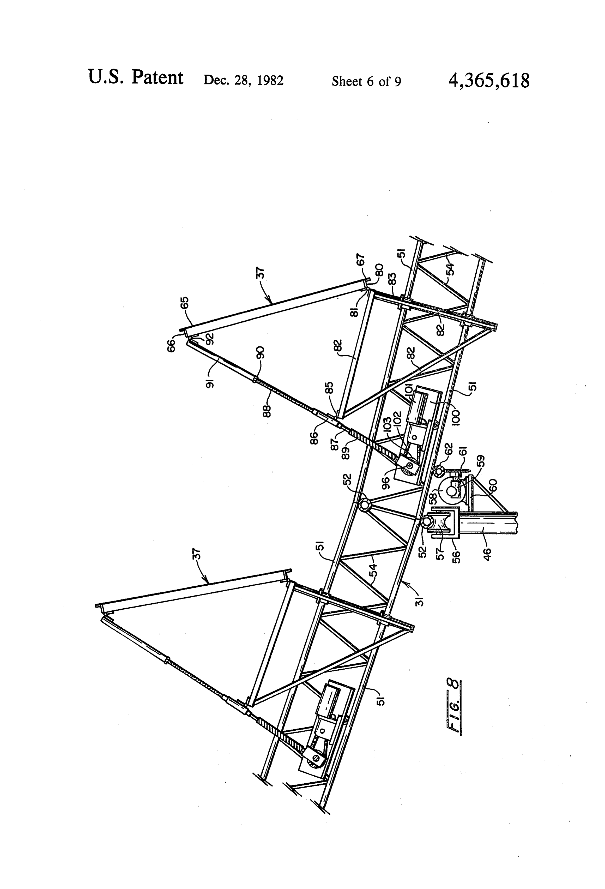
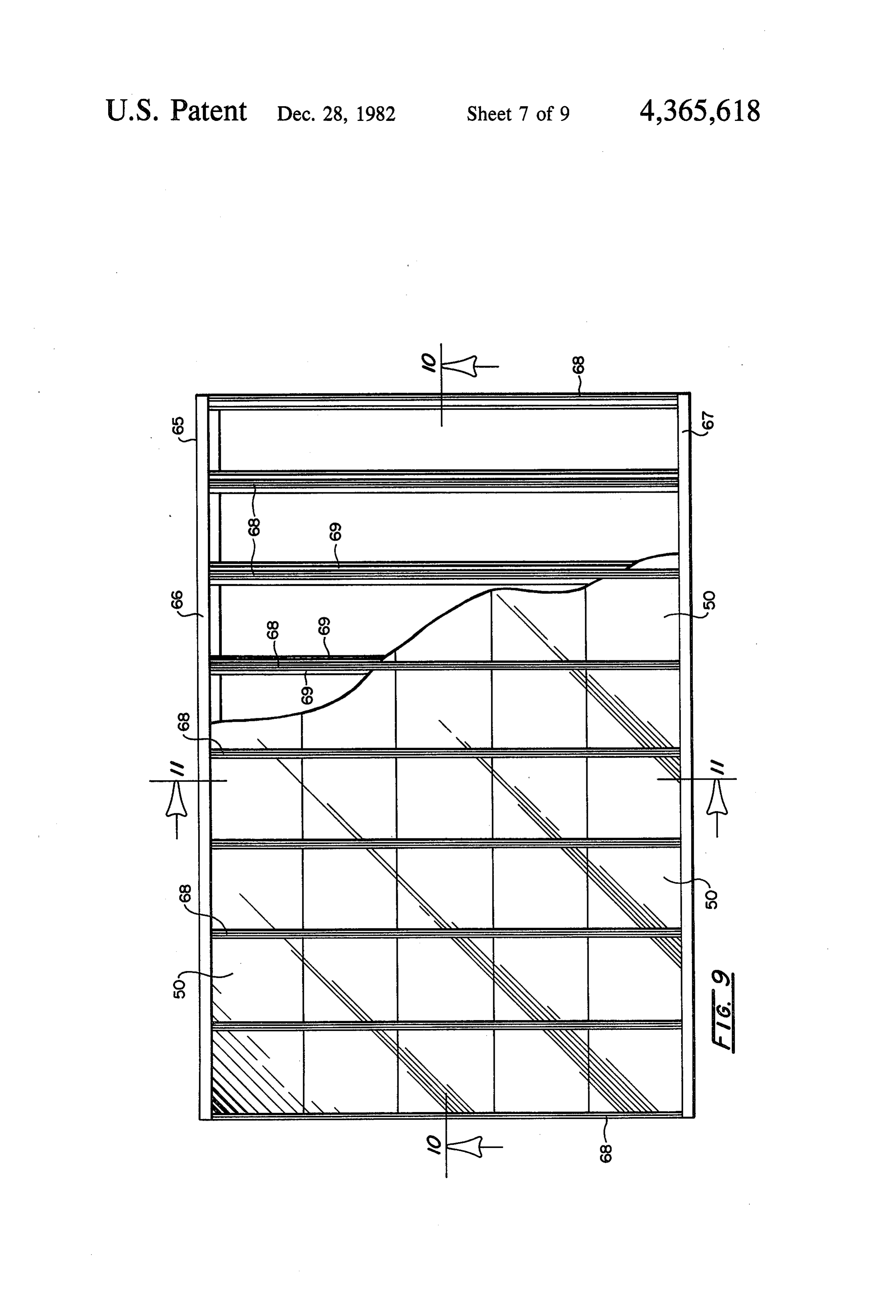
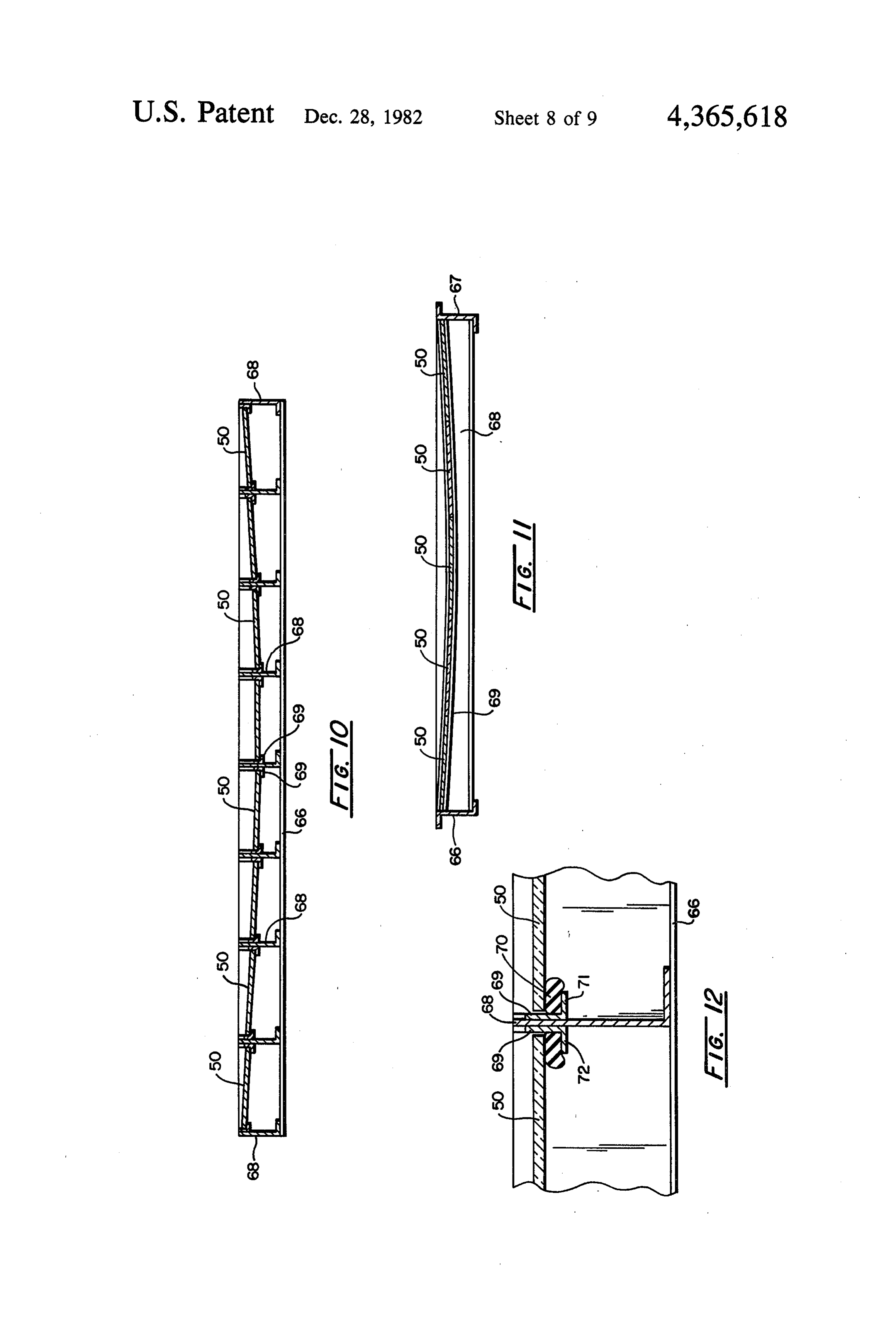
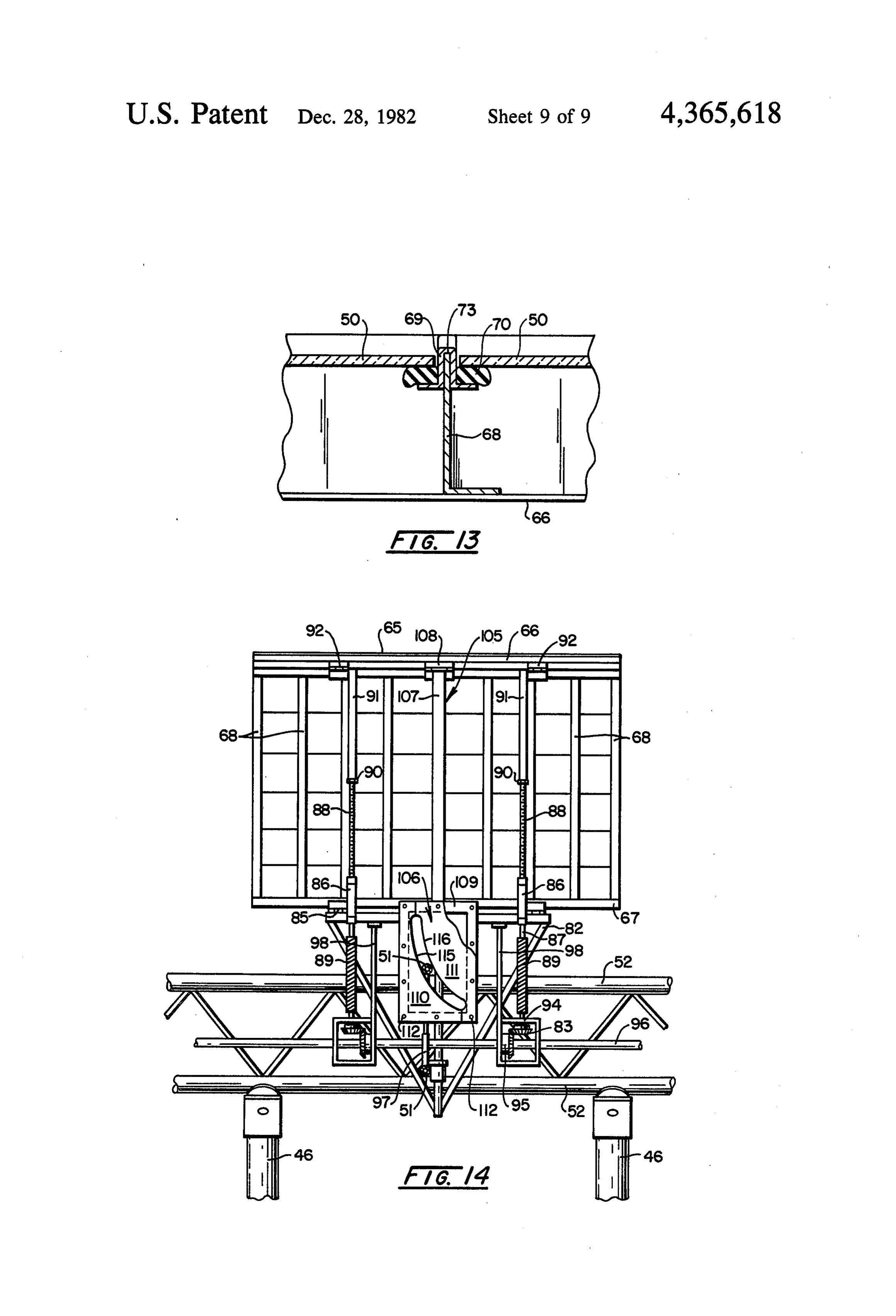
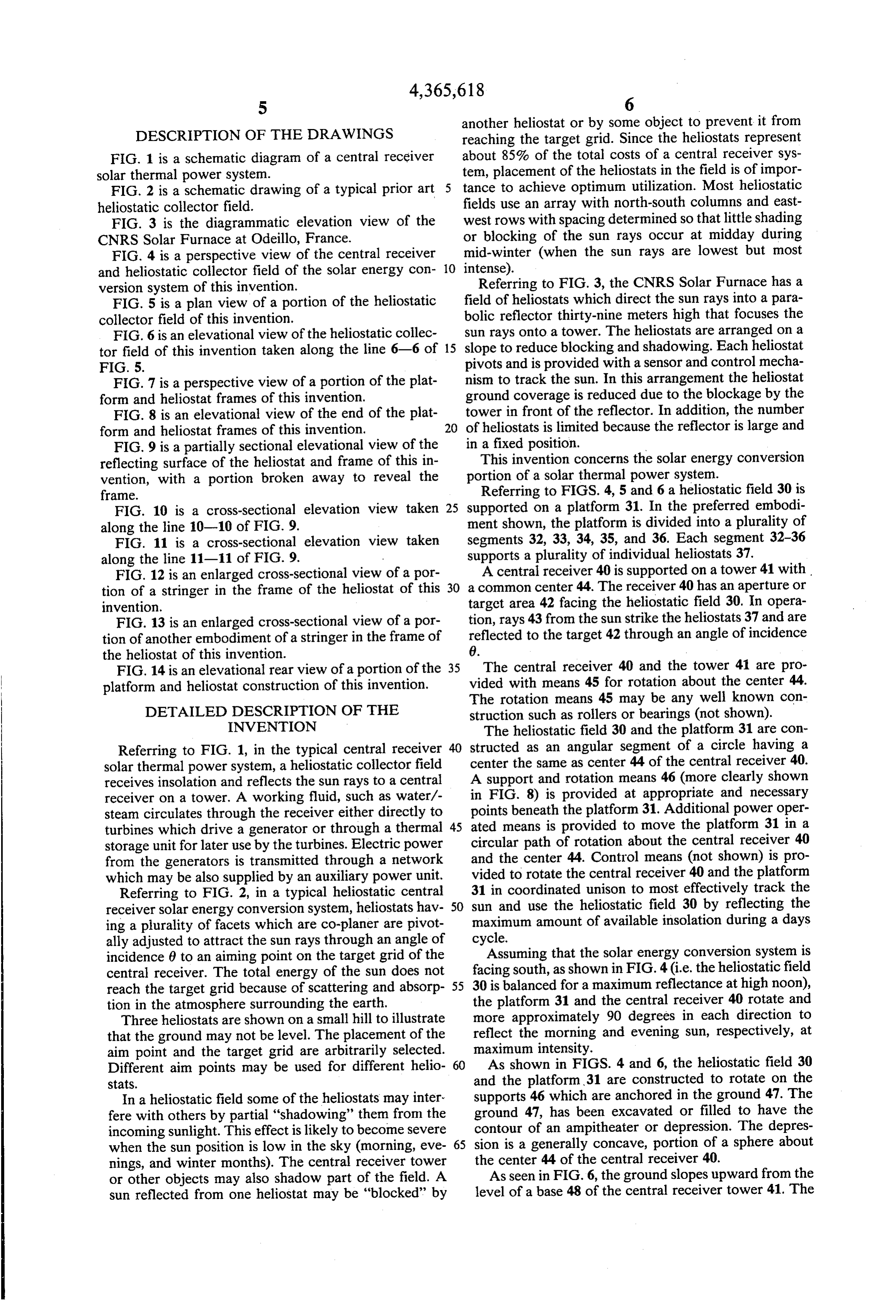
DESCRIPTION OF THE DRAWINGS reaching the target grid. Since the heliostats represent FIG. 1 is a schematic diagram of a central receiver about 85% of the total costs of a central receiver sys solar thermal power system. tem, placement of the heliostats in the field is of impor FIG. 2 is a schematic drawing of a typical prior art tance to achieve optimum utilization. Most heliostatic heliostatic collector field. fields use an array with north-south columns and east FIG. 3 is the diagrammatic elevation view of the west rows with spacing determined so that little shading CNRS Solar Furnace at Odeillo, France. or blocking of the sun rays occur at midday during FIG. 4 is a perspective view of the central receiver mid-winter (when the sun rays are lowest but most and heliostatic collector field of the solar energy con 10 intense).
version system of this invention. Referring to FIG. 3, the CNRS Solar Furnace has a FIG. 5 is a plan view of a portion of the heliostatic field of heliostats which direct the sun rays into a para collector field of this invention. bolic reflector thirty-nine meters high that focuses the FIG. 6 is an elevational view of the heliostatic collec sun rays onto a tower. The heliostats are arranged on a tor field of this invention taken along the line 6-6 of 15 slope to reduce blocking and shadowing. Each heliostat FIG. 5. pivots and is provided with a sensor and control mecha FIG. 7 is a perspective view of a portion of the plat nism to track the sun. In this arrangement the heliostat form and heliostat frames of this invention. ground coverage is reduced due to the blockage by the FIG. 8 is an elevational view of the end of the plat tower in front of the reflector. In addition, the number form and heliostat frames of this invention. 20 of heliostats is limited because the reflector is large and FIG. 9 is a partially sectional elevational view of the in a fixed position. w reflecting surface of the heliostat and frame of this in This invention concerns the solar energy conversion vention, with a portion broken away to reveal the portion of a solar thermal power system.
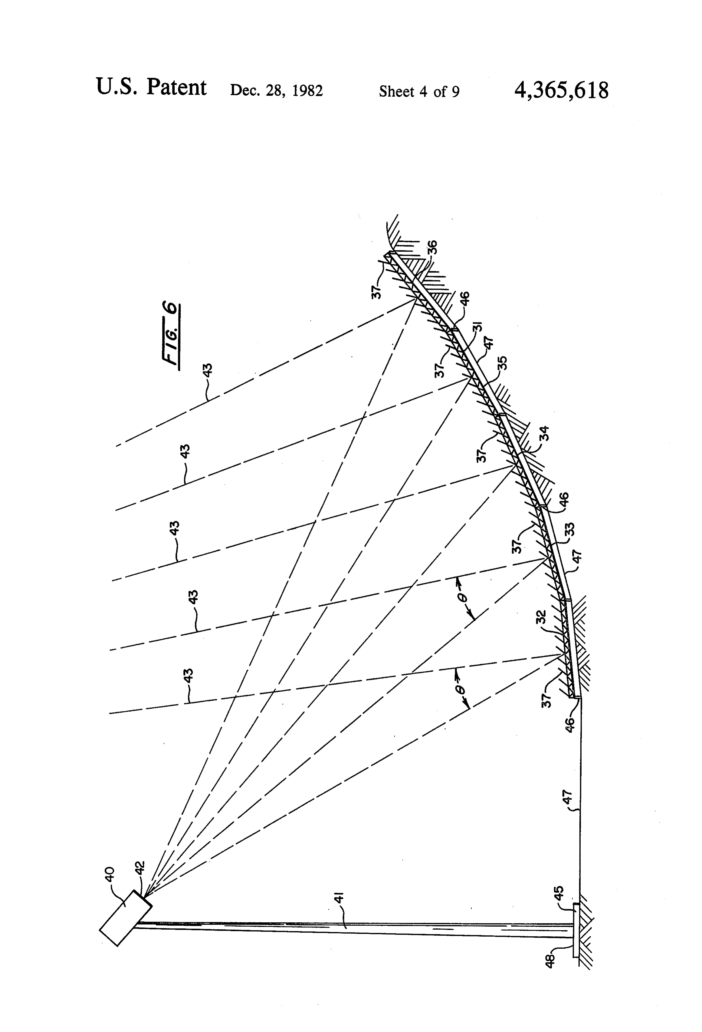
frame. Referring to FIGS. 4, 5 and 6 a heliostatic field 30 is FIG. 10 is a cross-sectional elevation view taken 25 supported on a platform 31. In the preferred embodi along the line 10-10 of FIG. 9. ment shown, the platform is divided into a plurality of FIG. 11 is a cross-sectional elevation view taken segments 32, 33, 34, 35, and 36. Each segment 32-36 along the line 11-11 of FIG. 9. - supports a plurality of individual heliostats 37. FIG. 12 is an enlarged cross-sectional view of a por A central receiver 40 is supported on a tower 41 with tion of a stringer in the frame of the heliostat of this 30 a common center 44. The receiver 40 has an aperture or invention. target area 42 facing the heliostatic field 30. In opera FIG. 13 is an enlarged cross-sectional view of a por tion, rays 43 from the sun strike the heliostats 37 and are tion of another embodiment of a stringer in the frame of reflected to the target 42 through an angle of incidence the heliostat of this invention. 69.
FIG. 14 is an elevational rear view of a portion of the vided The central receiver 40 and the tower 41 are pro platform and heliostat construction of this invention. with means 45 for rotation about the center 44.
DETAILED DESCRIPTION OF THE
The rotation means 45 may be any well known con struction such as rollers or bearings (not shown).
INVENTION The heliostatic field 30 and the platform 31 are con Referring to FIG. 1, in the typical central receiver 40 structed center as an angular segment of a circle having a the same as center 44 of the central receiver 40.
solar thermal power system, a heliostatic collector field receives insolation and reflects the sun rays to a central in A support and rotation means 46 (more clearly shown receiver on a tower. A working fluid, such as water/- FIG. 8) is provided at appropriate and necessary steam circulates through the receiver either directly to points beneath the platform 31. Additional power oper turbines which drive a generator or through a thermal 45 ated means is provided to move the platform 31 in a storage unit for later use by the turbines. Electric power circular path of rotation about the central receiver 40 from the generators is transmitted through a network and the center 44. Control means (not shown) is pro which may be also supplied by an auxiliary power unit. vided to rotate the central receiver 40 and the platform Referring to FIG. 2, in a typical heliostatic central 31 in coordinated unison to most effectively track the receiver solar energy conversion system, heliostats hav 50 sun and use the heliostatic field 30 by reflecting the ing a plurality of facets which are co-planer are pivot maximum amount of available insolation during a days ally adjusted to attract the sun rays through an angle of cycle.
incidence 6 to an aiming point on the target grid of the Assuming that the solar energy conversion system is central receiver. The total energy of the sun does not facing south, as shown in FIG. 4 (i.e. the heliostatic field reach the target grid because of scattering and absorp 55 30 is balanced for a maximum reflectance at high noon), tion in the atmosphere surrounding the earth. the platform 31 and the central receiver 40 rotate and Three heliostats are shown on a small hill to illustrate more approximately 90 degrees in each direction to that the ground may not be level. The placement of the reflect the morning and evening sun, respectively, at aim point and the target grid are arbitrarily selected. maximum intensity.
Different aim points may be used for different helio 60 As shown in FIGS. 4 and 6, the heliostatic field 30 Stats. and the platform 31 are constructed to rotate on the In a heliostatic field some of the heliostats may inter supports 46 which are anchored in the ground 47. The fere with others by partial "shadowing' them from the ground 47, has been excavated or filled to have the incoming sunlight. This effect is likely to become severe contour of an ampitheater or depression. The depres when the sun position is low in the sky (morning, eve 65 sion is a generally concave, portion of a sphere about nings, and winter months). The central receiver tower the center 44 of the central receiver 40. or other objects may also shadow part of the field. A level As seen in FIG. 6, the ground slopes upward from the sun reflected from one heliostat may be “blocked' by of a base 48 of the central receiver tower 41. The
Page 14
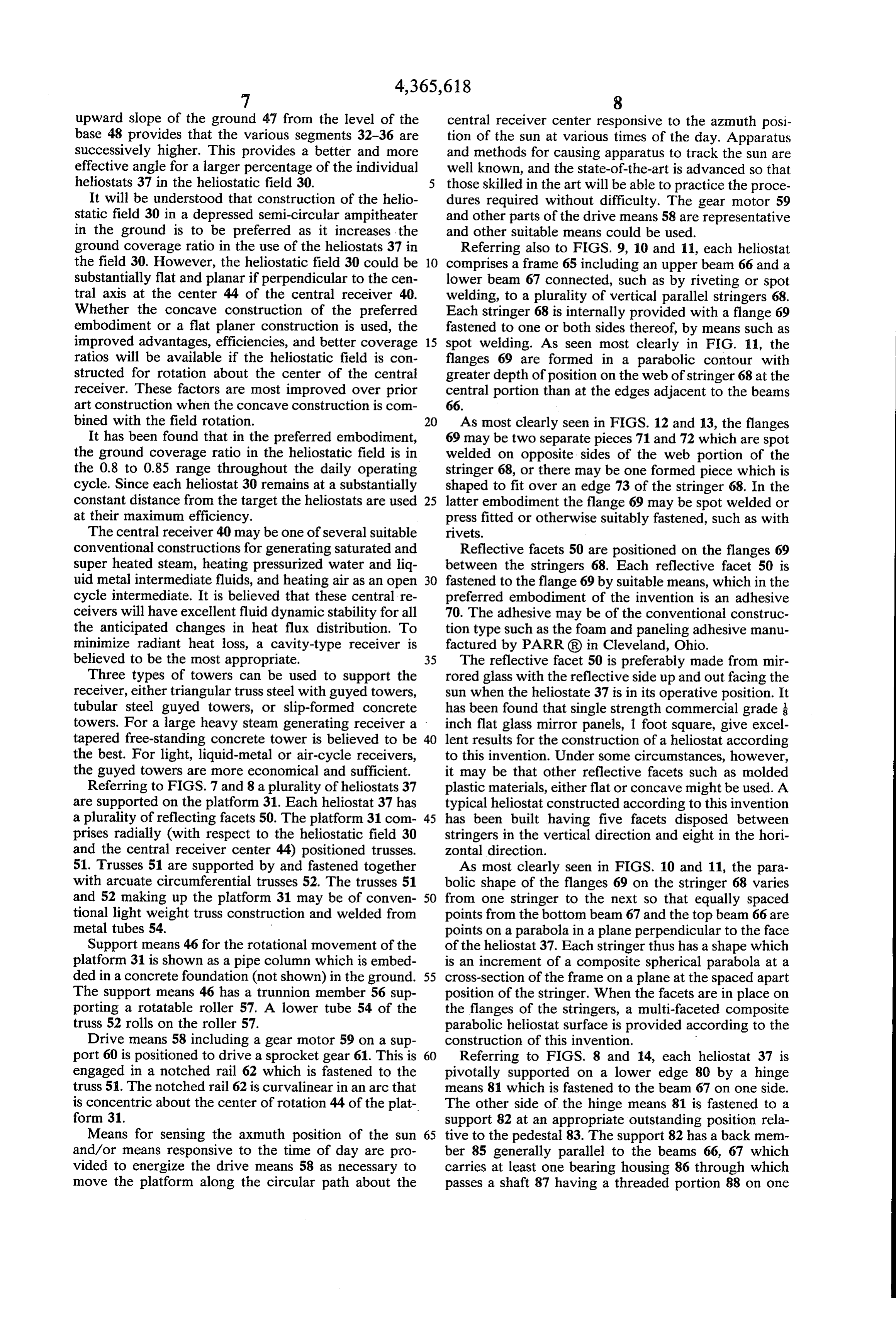
upward slope of the ground 47 from the level of the central receiver center responsive to the azmuth posi base 48 provides that the various segments 32-36 are tion of the sun at various times of the day. Apparatus successively higher. This provides a better and more and methods for causing apparatus to track the sun are effective angle for a larger percentage of the individual well known, and the state-of-the-art is advanced so that heliostats 37 in the heliostatic field 30. those skilled in the art will be able to practice the proce It will be understood that construction of the helio dures required without difficulty. The gear motor 59 static field 30 in a depressed semi-circular ampitheater and other parts of the drive means 58 are representative in the ground is to be preferred as it increases, the and other suitable means could be used. ground coverage ratio in the use of the heliostats 37 in Referring also to FIGS. 9, 10 and 11, each heliostat the field 30. However, the heliostatic field 30 could be 10 comprises a frame 65 including an upper beam 66 and a substantially flat and planar if perpendicular to the cen lower beam 67 connected, such as by riveting or spot tral axis at the center 44 of the central receiver 40. welding, to a plurality of vertical parallel stringers 68. Whether the concave construction of the preferred Each stringer 68 is internally provided with a flange 69 embodiment or a flat planer construction is used, the fastened to one or both sides thereof, by means such as improved advantages, efficiencies, and better coverage 15 spot welding. As seen most clearly in FIG. 11, the ratios will be available if the heliostatic field is con flanges 69 are formed in a parabolic contour with structed for rotation about the center of the central greater depth of position on the web of stringer 68 at the receiver. These factors are most improved over prior central portion than at the edges adjacent to the beams art construction when the concave construction is com 66.
bined with the field rotation. 20 As most clearly seen in FIGS. 12 and 13, the flanges It has been found that in the preferred embodiment, 69 may be two separate pieces 71 and 72 which are spot the ground coverage ratio in the heliostatic field is in welded on opposite sides of the web portion of the the 0.8 to 0.85 range throughout the daily operating stringer 68, or there may be one formed piece which is cycle. Since each heliostat 30 remains at a substantially shaped to fit over an edge 73 of the stringer 68. In the constant distance from the target the heliostats are used 25 latter embodiment the flange 69 may be spot welded or at their maximum efficiency. press fitted or otherwise suitably fastened, such as with The central receiver 40 may be one of several suitable rivets.
conventional constructions for generating saturated and Reflective facets 50 are positioned on the flanges 69 super heated steam, heating pressurized water and liq between the stringers 68. Each reflective facet 50 is uid metal intermediate fluids, and heating air as an open 30 fastened to the flange 69 by suitable means, which in the cycle intermediate. It is believed that these central re preferred embodiment of the invention is an adhesive ceivers will have excellent fluid dynamic stability for all 70. The adhesive may be of the conventional construc the anticipated changes in heat flux distribution. To tion type such as the foam and paneling adhesive manu minimize radiant heat loss, a cavity-type receiver is factured by PARR(R) in Cleveland, Ohio. believed to be the most appropriate. 35 The reflective facet 50 is preferably made from mir Three types of towers can be used to support the rored glass with the reflective side up and out facing the receiver, either triangular truss steel with guyed towers, sun when the heliostate 37 is in its operative position. It tubular steel guyed towers, or slip-formed concrete has been found that single strength commercial grade is towers. For a large heavy steam generating receiver a inch flat glass mirror panels, 1 foot square, give excel tapered free-standing concrete tower is believed to be 40 lent results for the construction of a heliostat according the best. For light, liquid-metal or air-cycle receivers, to this invention. Under some circumstances, however, the guyed towers are more economical and sufficient. it may be that other reflective facets such as molded Referring to FIGS. 7 and 8 a plurality of heliostats 37 plastic materials, either flat or concave might be used. A are supported on the platform 31. Each heliostat 37 has typical heliostat constructed according to this invention a plurality of reflecting facets 50. The platform 31 com 45 has been built having five facets disposed between prises radially (with respect to the heliostatic field 30 stringers in the vertical direction and eight in the hori and the central receiver center 44) positioned trusses. zontal direction.
51. Trusses 51 are supported by and fastened together As most clearly seen in FIGS. 10 and 11, the para with arcuate circumferential trusses 52. The trusses 51 bolic shape of the flanges 69 on the stringer 68 varies and 52 making up the platform 31 may be of conven 50 from one stringer to the next so that equally spaced tional light weight truss construction and welded from points from the bottom beam 67 and the top beam 66 are metal tubes 54. points on a parabola in a plane perpendicular to the face Support means 46 for the rotational movement of the of the heliostat 37. Each stringer thus has a shape which platform 31 is shown as a pipe column which is embed is an increment of a composite spherical parabola at a ded in a concrete foundation (not shown) in the ground. 55 cross-section of the frame on a plane at the spaced apart The support means 46 has a trunnion member 56 sup position of the stringer. When the facets are in place on porting a rotatable roller 57. A lower tube 54 of the the flanges of the stringers, a multi-faceted composite truss 52 rolls on the roller 57. parabolic heliostat surface is provided according to the Drive means 58 including a gear motor 59 on a sup construction of this invention.
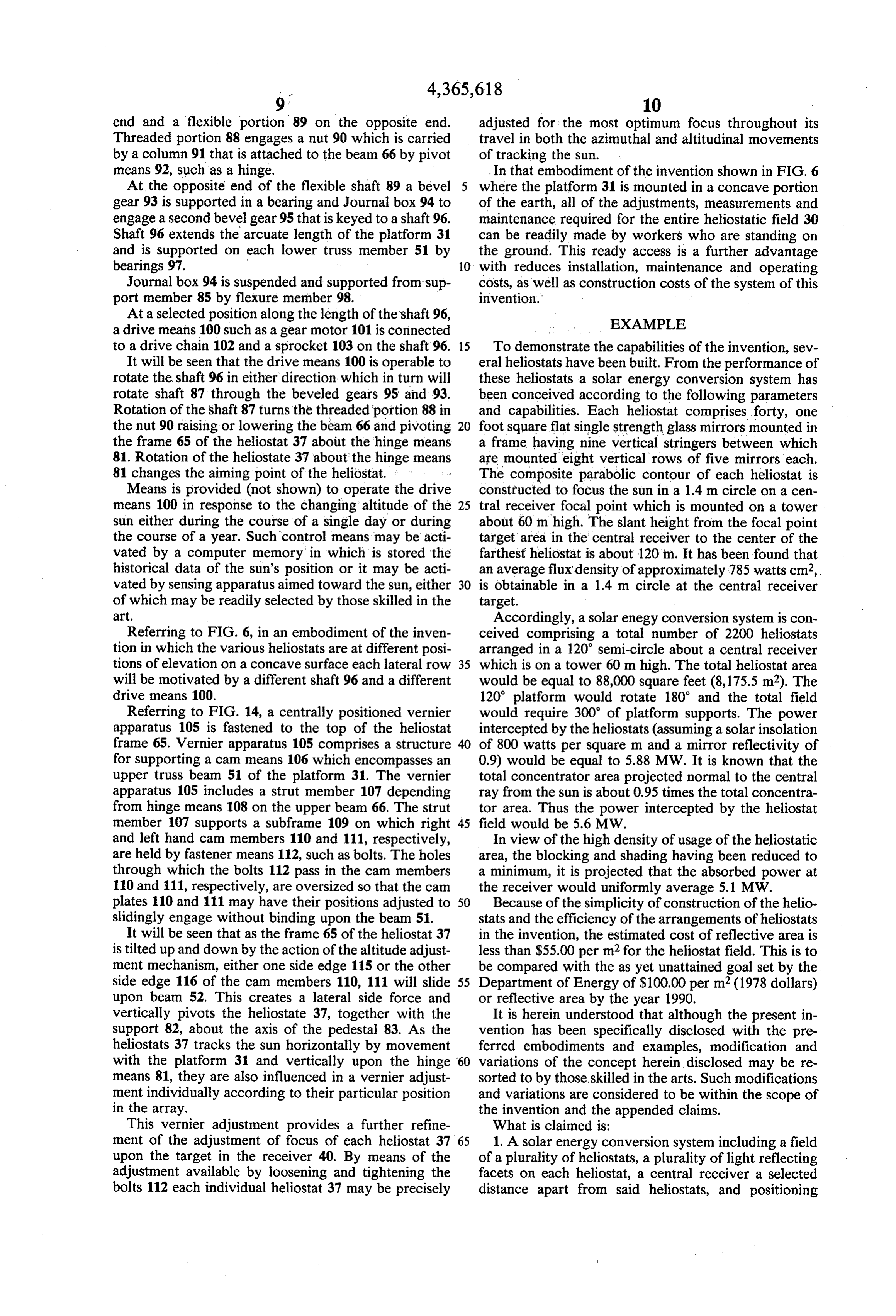
port 60 is positioned to drive a sprocket gear 61. This is 60 Referring to FIGS. 8 and 14, each heliostat 37 is engaged in a notched rail 62 which is fastened to the pivotally supported on a lower edge 80 by a hinge truss 51. The notched rail 62 is curvalinear in an arc that means 81 which is fastened to the beam 67 on one side. is concentric about the center of rotation 44 of the plat The other side of the hinge means 81 is fastened to a form 31. support 82 at an appropriate outstanding position rela Means for sensing the aximuth position of the sun 65 tive to the pedestal 83. The support 82 has a back mem and/or means responsive to the time of day are pro ber 85 generally parallel to the beams 66, 67 which vided to energize the drive means 58 as necessary to carries at least one bearing housing 86 through which move the platform along the circular path about the passes a shaft 87 having a threaded portion 88 on one
Page 15
end and a flexible portion 89 on the opposite end. adjusted for the most optimum focus throughout its Threaded portion 88 engages a nut 90 which is carried travel in both the azimuthal and altitudinal movements by a column 91 that is attached to the beam 66 by pivot of tracking the sun.
means 92, such as a hinge. In that embodiment of the invention shown in FIG. 6 At the opposite end of the flexible shaft 89 a bevel where the platform 31 is mounted in a concave portion gear 93 is supported in a bearing and Journal box 94 to of the earth, all of the adjustments, measurements and engage a second bevel gear 95 that is keyed to a shaft 96. maintenance required for the entire heliostatic field 30 Shaft 96 extends the arcuate length of the platform 31 can be readily made by workers who are standing on and is supported on each lower truss member 51 by the ground. This ready access is a further advantage bearings 97. 10 with reduces installation, maintenance and operating Journal box 94 is suspended and supported from sup costs, as well as construction costs of the system of this port member 85 by flexure member 98. invention.
At a selected position along the length of the shaft 96, a drive means 100 such as a gear motor 101 is connected EXAMPLE to a drive chain 102 and a sprocket 103 on the shaft 96. 15 To demonstrate the capabilities of the invention, sev It will be seen that the drive means 100 is operable to eral heliostats have been built. From the performance of rotate the shaft 96 in either direction which in turn will these heliostats a solar energy conversion system has rotate shaft 87 through the beveled gears 95 and 93. been conceived according to the following parameters Rotation of the shaft 87 turns the threaded portion 88 in and capabilities. Each heliostat comprises forty, one the nut 90 raising or lowering the beam 66 and pivoting 20 foot square flat single strength glass mirrors mounted in the frame 65 of the heliostat 37 about the hinge means a frame having nine vertical stringers between which 81. Rotation of the heliostate 37 about the hinge means are mounted eight vertical rows of five mirrors each. 81 changes the aiming point of the heliostat. The composite parabolic contour of each heliostat is Means is provided (not shown) to operate the drive constructed to focus the sun in a 1.4 m circle on a cen means 100 in response to the changing altitude of the 25 tral receiver focal point which is mounted on a tower sun either during the course of a single day or during about 60 m high. The slant height from the focal point the course of a year. Such control means may be acti target area in the central receiver to the center of the vated by a computer memory in which is stored the farthest heliostat is about 120 m. It has been found that historical data of the sun's position or it may be acti an average flux density of approximately 785 watts cm2, vated by sensing apparatus aimed toward the sun, either 30 is obtainable in a 1.4 m circle at the central receiver of which may be readily selected by those skilled in the target.
art. Accordingly, a solar enegy conversion system is con Referring to FIG. 6, in an embodiment of the inven ceived comprising a total number of 2200 heliostats tion in which the various heliostats are at different posi arranged in a 120 semi-circle about a central receiver tions of elevation on a concave surface each lateral row 35 which is on a tower 60 m high. The total heliostat area will be motivated by a different shaft 96 and a different would be equal to 88,000 square feet (8,175.5 m2). The drive means 100. 120' platform would rotate 180 and the total field Referring to FIG. 14, a centrally positioned vernier would require 300 of platform supports. The power apparatus 105 is fastened to the top of the heliostat intercepted by the heliostats (assuming a solar insolation frame 65. Vernier apparatus 105 comprises a structure of 800 watts per square m and a mirror reflectivity of for supporting a can means 106 which encompasses an 0.9) would be equal to 5.88 MW. It is known that the upper truss beam 51 of the platform 31. The vernier total concentrator area projected normal to the central apparatus 105 includes a strut member 107 depending ray from the sun is about 0.95 times the total concentra from hinge means 108 on the upper beam 66. The strut tor area. Thus the power intercepted by the heliostat member 107 supports a subframe 109 on which right 45 field would be 5.6 MW.
and left hand cam members 110 and 111, respectively, In view of the high density of usage of the heliostatic are held by fastener means 112, such as bolts. The holes area, the blocking and shading having been reduced to through which the bolts 112 pass in the cam members a minimum, it is projected that the absorbed power at 110 and 111, respectively, are oversized so that the cam the receiver would uniformly average 5.1 MW. plates 110 and 111 may have their positions adjusted to 50 Because of the simplicity of construction of the helio slidingly engage without binding upon the beam 51. stats and the efficiency of the arrangements of heliostats It will be seen that as the frame 65 of the heliostat 37 in the invention, the estimated cost of reflective area is is tilted up and down by the action of the altitude adjust less than $55.00 per m2 for the heliostat field. This is to ment mechanism, either one side edge 115 or the other be compared with the as yet unattained goal set by the side edge 116 of the cam members 110, 111 will slide 55 Department of Energy of $100.00 per m2 (1978 dollars) upon beam 52. This creates a lateral side force and or reflective area by the year 1990.
vertically pivots the heliostate 37, together with the It is herein understood that although the present in support 82, about the axis of the pedestal 83. As the vention has been specifically disclosed with the pre heliostats 37 tracks the sun horizontally by movement ferred embodiments and examples, modification and with the platform 31 and vertically upon the hinge 60 variations of the concept herein disclosed may be re means 81, they are also influenced in a vernier adjust sorted to by those skilled in the arts. Such modifications ment individually according to their particular position and variations are considered to be within the scope of in the array. the invention and the appended claims. This vernier adjustment provides a further refine What is claimed is:
ment of the adjustment of focus of each heliostat 37 65 1. A solar energy conversion system including a field upon the target in the receiver 40. By means of the of a plurality of heliostats, a plurality of light reflecting adjustment available by loosening and tightening the facets on each heliostat, a central receiver a selected bolts 112 each individual heliostat 37 may be precisely distance apart from said heliostats, and positioning
Page 16
means to position each heliostat to focus the rays of the with the central receiver as a center in the horizontal sun on the central receiver, comprising: plane.
(a) at least one platform supporting a plurality of 3. A solar energy conversion system according to claim 1 wherein a portion of the frames are arranged on heliostats with each heliostat constituting a frame 5 the platform having edges and supporting a plurality of reflect cessively larger at successively higher elevations and suc ing facets fixidly positioned on the frame, which in angles relative to the horizontal plane. 4. A solar energy conversion system according to combination comprise a multi-faceted composite claim 3 wherein means is provided to move each plat parabolic heliostat surface, with each heliostat fo form along the circular path about the central receiver cused on the central receiver; 10 center responsive to the azimuth position of the sun at (b) each platform being constructed of at least one various times of a day.
truss member curved to substantially match a cir 5. A solar energy conversion system according to cumferential curve with respect to the central re claim 4 wherein means is provided to move each plat ceiver, each platform being moveable in a substan form along the circular path about the central receiver tially circular path in a horizontal plane about the 15 center responsively to the aximuth position of the sun at central receiver as a center, at least one of the various times of a year.
curved truss members being supported by a plural 6. A solar energy conversion system according to ity of rollers mounted on supporting means in the claim about 5 wherein means is provided to rotate each frame said other perpendicular axis responsive to the ground; and 20 position of the platform in its circular path about the (c) each frame pivotally mounted on a platform for central receiver center.
movement about two axes, one axis generally tan 7. A solar conversion energy system according to gential to the circumferential curve, and the other claim 1 wherein the facets are glass mirrors. axis generally perpendicular to the horizontal 8. A solar energy conversion system according to plane. 25 claim 7 wherein the mirrors are flat. 2. A solar energy conversion system according to 9. A solar energy conversion system according to claim 1 wherein the supporting roller means are ar claim 1 in which each curved truss member is con ranged in a concave depression in the ground which is structed as a segmentck ofsk a circle. substantially and generally semi-spherically shaped sk sk sk
Provenance
- Collection
- Cited prior art
- Original PDF
- patentimages.storage.googleapis.com →
- Filed
- 1980-12-05
- Pages
- 16
- Method
- pdftotext (the PDF's own text layer) + pdftoppm 300dpi page scans
- Source
- Google Patents bibliographic record
- Granted
- 1982-12-28
- Inventors
- Dedger Jones
- Transcribed from
- patentimages.storage.googleapis.com →