patent · US4338114
Laser treatment method for imparting increased mechanical strength to glass objects
6 July 1982
Page 1 — bibliographic record
29 al 2 SR
United States Patent (19) 11) 4,338,114 Brockway et al. 45) Jul. 6, 1982 (54) LASER TREATMENT METHOD FOR 3,839,005 10/1974 Meyer ................................... 65/112 IMPARTING INCREASED MECHANICAL 3,944,640 3/1976 Haggerty et al... ... 264/25 STRENGTH TO GLASS OBJECTS 4,025,328 5/1977 Polaert et al. ........................ 65/11
75 Inventors: M. Clifford Brockway; Craig T. 4, 170,726 10/1979 Okuda .......................... 219/121 LF Walters, both of Columbus, Ohio Primary Examiner-Arthur D. Kellogg 73 Assignee: Liberty Glass Company, Sapulpa, Attorney, Agent, or Firm-Senniger, Powers, Leavitt Okla. and Roedel (21) Appl. No.: 180,140 57 ABSTRACT 22 Filed: Aug. 21, 1980 A method for imparting increased mechanical strength (51) Int. Cl............................................... CO3B 29/02 to a glass object having imperfections in a surface (52) U.S. Cl. .......................................... 65/28; 65/104; thereof. The glass object is heated to a temperature 65/111; 65/DIG. 4; 219/121 LE; 219/121 LF; above the strain point of the glass. A laser beam is gen 219/121 LM erated having a wavelength absorbable by the glass and (58 Field of Search ............. 65/28, 104, 111, DIG. 4, impinged on all portions of the surface containing the 65/284, 112, 120; 219/121 LE, 121 EM, 121 imperfections. The power density at which the beam is LM, 121 LF impinged is sufficient to rapidly heat a surface stratum 56) References Cited of the glass to establish a thermal gradient therein whereby the viscosity at a depth from the surface suffi
3,259,480 7/1966 Michalik et al. ........................ 65/28 the stress induced by the surface tension of the glass at 3,538,298 11/1970 Duston et al. ...................... 219/121 the sites of the imperfections is sufficient to cause flow 3,588,440 6/1971 Morse .................................. 219/121 of glass and effect a reforming of the glass surface at 3,656,922 4/1972 Budd................................. 65/111 X said sites.
3,663,793 5/1972 Petro et al. ... 219/121. LM 3,756,799 9/1973 Neuroth .................................. 65/18 3,764,776 10/1973 Hierholzer .................. 219/121 LM 29 Claims, 7 Drawing Figures
Page 2
Drawing sheet — no readable text.
Page 3
Drawing sheet — no readable text.
Page 4
Drawing sheet — no readable text.
Page 5
Drawing sheet — no readable text.
Page 6
Drawing sheet — no readable text.
Page 7
sive stress in the surface zone or skin of the glass. The
LASER TREATMENT METHOD FOR IMPARTING purpose of such a residual compression zone is to place INCREASED MECHANICAL STRENGTH TO the imperfections under compression. In such circum GLASS OBJECTS stance, the defects can initiate fracture only when they are subjected to sufficient levels oftensile stress to over
BACKGROUND OF THE INVENTION come the residual compressive stress and reach the This invention relates to the field of treatment of glass tensile stress levels at which fracture propagation can objects for increasing the mechanical strength thereof occur. The net practical effect is that the observed ser and, more particularly, to a novel method for increasing vice tensile strength of the glass is increased by the service strength through the reforming of surface de O magnitude of the residual compressive stress. fects or flaws. There are a number of known techniques for creating In order to promote safety and serviceability, exten residual compressive stress in glass. Among the most sive research has been devoted to the objective of in practical are thermal tempering, application of case creasing the strength of glass objects, and most espe 15 glass, and strengthening by ion exchange. Thermal tem cially, their resistance to damage and failure under con pering is normally effective only on thicknesses greater ditions of practical usage and handling. Since glass is widely used in packaging, particularly in containers for than tions about inch, making it suitable for some applica but not satisfactory for the strengthening of glass beverages, including carbonated beverages, much of the objects such as containers for carbonated beverages. research has been devoted to strengthening techniques Tempering is an especially unpromising alternative for adapted to the configuration, service and handling con 20 beverage bottles since the industry is continuing to ditions encountered with glass containers.
It has long been recognized that glass is intrinsically move in the direction of lighter weight non-returnable a very strong material. Based on the energy of the Si-O bottles. In the case glass method, a layer of glass is bond, the theoretical intrinsic strength of silica glass has 25 bonded to a surface of a glass object to provide a region been estimated at 2,000,000 psi or greater. Because of that is under residual compressive stress. Such an ap the effect of surface imperfections, however, the nomi proach is complicated and expensive, and not well nal tensile strength of annealed glass is commonly only adapted to mass production operations such as the man about 7,000 psi. Such surface defects act as stress multi ufacture of glass beverage bottles. pliers which can raise a nominally applied stress, such as One of the more attractive alternatives for providing 7,000 psi, to sufficiently high levels at flaw sites to cause 30 a layer of residual compressive stress is ion exchange. In fracture initiation of the glass structure. Once fracture is accordance with this technique the outer margin of the initiated, it can propagate catastrophically through the glass is reacted with a salt whose cations have ionic glass structure because glass is a brittle material and diameters different from the principal cations of the high local stresses are not relieved by plastic flow.
Work in the field of the mechanics of glass structures 35 glass, Where the ion exchange salt contains larger cati has established that glass fracture initiation starts almost process compressive ons, the is referred stress is directly produced and the to as ion stuffing. Where smaller exclusively at surface defects. The characteristics of diameter cations are used, a marginal stratum is gener these defects, including their geometry, depth of pene ated having a lower coefficient of thermal expansion tration, orientation relative to the surface, etc. deter mine the extent to which they magnify an average ap 40 than the bulk of the glass so that, on cooling from the plied tensile stress. Because glass is known to fail under temperature at which the exchange reaction is con tensile stress, the extent of magnification of applied ducted, the outer margin is placed under compressive stress largely determines the observed nominal strength stress.
of a glass object. Despite its demonstrated effectiveness, the ion ex In order to increase the mechanical service strength 45 change process has not found widespread application in of glass objects to a higher proportion of the theoretical the manufacture of beverage bottles. The major prob strength, two basic avenues have conventionally been lem is the handling of the ion exchange salt. This mate pursued. One approach is to attempt the production of rial must be applied to the outside of the container in a glass objects having minimal surface defects, or with molten bath, an aqueous solution spray, or as an air defects of a type which cause the least magnification of 50 conveyed dust. Each of these techniques involves sig nominal applied tensile stresses. According to this ap nificant capital investment, operating and maintenance proach, very high strength levels have been achieved costs. Additionally, residual ion exchange material and by the application of chemical reagents or solvents to ion exchange reaction products adhere to the outside of remove from the object the surface margin which con the container or other glass object after the reaction tains the flaws, defects and other imperfections. Tensile 55 strength levels up to several hundred thousand psi have step is complete. This material must be removed in a been reported with this approach using a number of ered andwashing separate recycled step, and either discarded or recov for treatment of additional glass.
reagents, most commonly HF solutions. However, a Such recovery and recycle major limitation of this approach arises from its low Also even where a recyclefacilities add to the expense. operation is carried out, a productivity and high cost. In order to achieve the 60 desired strength improvement it may be necessary to purge stream is required to dispose of products of the ion exchange reaction. This brings environmental con remove as much as 2 mils of glass. The hazards of work siderations ing with potent chemical reagents such as HF and the into play and may require further expense problems of disposal thereof are further deterrents to for disposal facilities.
the practical commercial implementation of this ap 65 An unfulfilled need has remained in the art, therefore, proach. for an improved method for the clean, economical pro The second major approach to improving the service duction of high service strength glass objects, most strength of glass objects is to create residual compres particularly glass bottles.
Page 8
SUMMARY OF THE INVENTION DESCRIPTION OF THE PREFERRED
Among the several objects of the present invention, EMBODIMENTS therefore, may be noted the provision of an improved In accordance with the present invention, it has been method for increasing the mechanical strength of glass 5 discovered that the mechanical service strength of glass objects; the provision of such a method which can be objects can be materially enhanced by reforming an carried out at high productivity and relatively low pro outer surface thereof through controlled laser treatment cessing costs; the provision of such a method which to eliminate imperfections in such surface. The method requires no post-treatment step to clean the strength of the invention is applicable to the strengthening of ened object nor to recover and recycle treatment mate O various glass objects including solid rods and glass con rials; the provision of such a method which requires no tainers. It is particularly advantageous for the treatment chemical reactants; the provision of such a method of carbonated beverage bottles, which require substan which requires no recycle of processing material; the tial strength for containment of carbonated liquids at provision of such a method which is applicable to im pressures as high as 50 psig. By reforming the glass proving the strength of glass containers; the provision 15 surface to minimize imperfections and substantially of such a method which may be used to treat and in increase glass tensile strength under service conditions, implementation of the method of the invention is ex crease the mechanical strength of glass containers hav pected ing either thick or thin walls; the provision of such a to permit the production of extra light weight method which is amenable to process automation and 20 non-returnable carbonated beverage bottles which safely contain beverages under conditions of usage and precise control; and the provision of such a method handling.
which can be carried out with relatively low overall By impinging a laser beam on a portion of a glass energy consumption. surface containing imperfections, a surface stratum of Briefly, therefore, the present invention is directed to the glass is rapidly heated by absorption of energy at the a novel method for imparting increased mechanical 25 high power density realized in a laser beam. A thermal strength to a glass object having imperfections on the gradient is established in the surface stratum with a surface thereof. In the method, the object is heated to a corresponding viscosity gradient in inverse relation to temperature above the strain point of the glass. A laser the temperature gradient. The surface stratum is heated beam is generated having a wavelength absorbable by sufficiently that the viscosity at a depth from the surface the glass. The beam is impinged on all portions of the 30 sufficient to encompass the surface imperfections is low surface containing the imperfections at a power density enough that the stress induced by the surface tension of sufficiently to rapidly heat a surface stratum of the glass the glass of the sites of the imperfections is sufficient to to establish a thermal gradient therein whereby the cause flow of the glass and effect reforming of the glass viscosity at a depth from the surface sufficient to en surface at those sites.
compass the imperfections is low enough that the stress 35 In order to prevent deformation or fracture of the induced by the surface tension of the glass at the sites of glass object due to thermal stresses generated by laser the imperfections is sufficient to cause flow of the glass heating of the surface stratum, the entire object is and thus effect a reforming of the glass surface at such heated prior to impingement of the laser beam on the sites. surface thereof. The object must be heated to at least Other objects and features will be in part apparent the strain point of the glass, i.e., the temperature at and in part pointed out hereinafter. which the viscosity is 1014.7, which for conventional
BRIEF DESCRIPTION OF THE DRAWINGS
soda/lime glass is approximately 907 F. Preferably, the glass object is preheated to the annealing range, defined
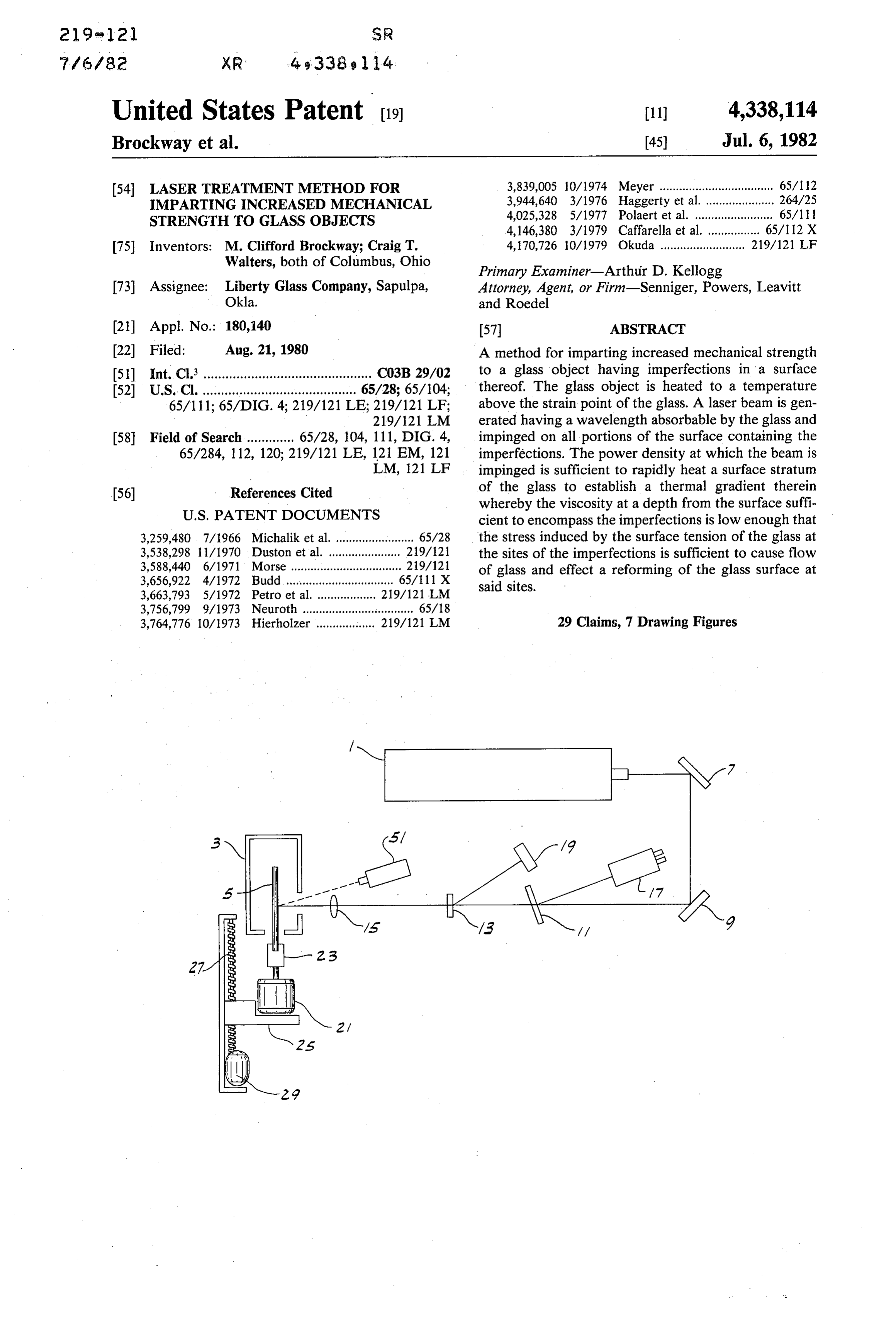
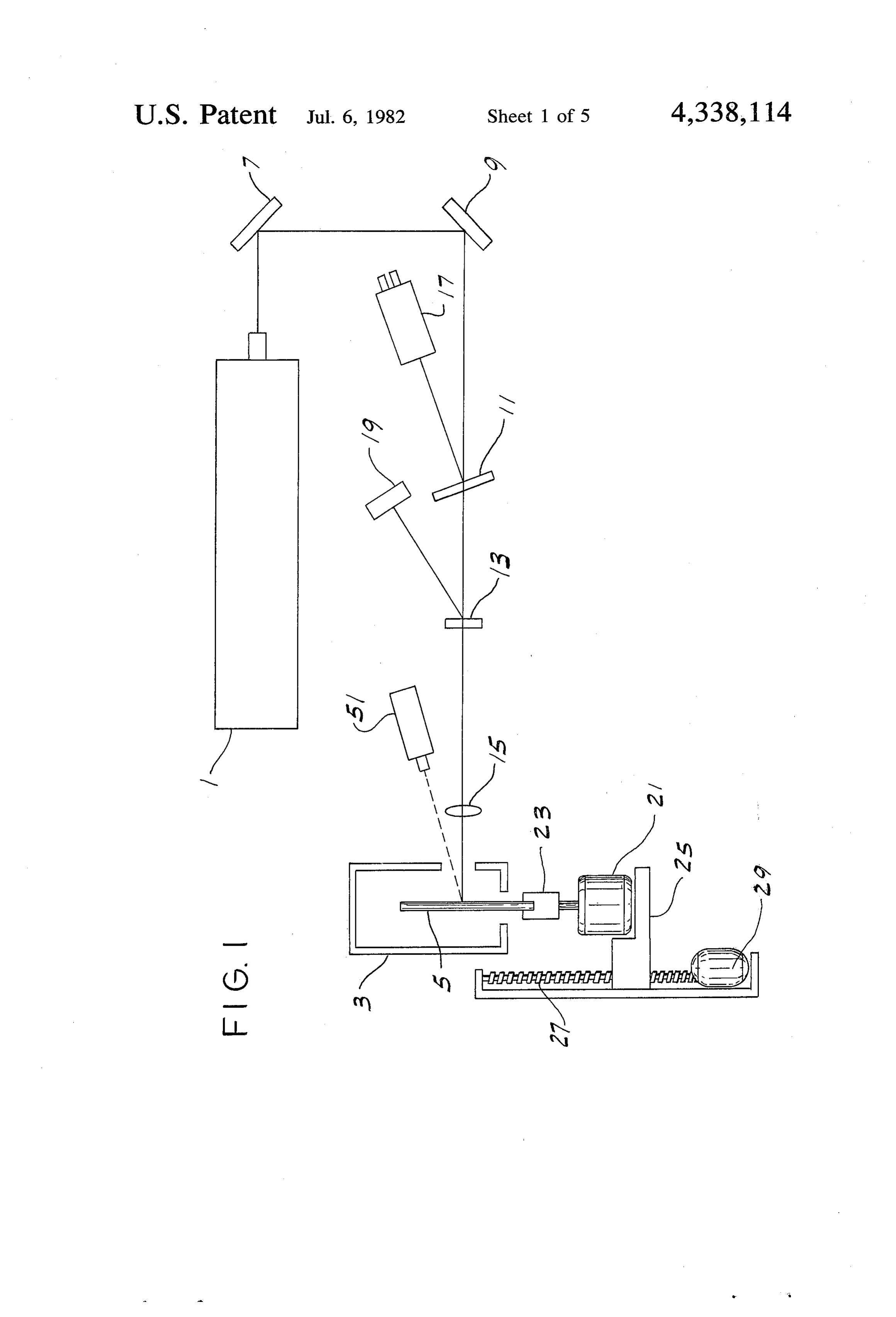
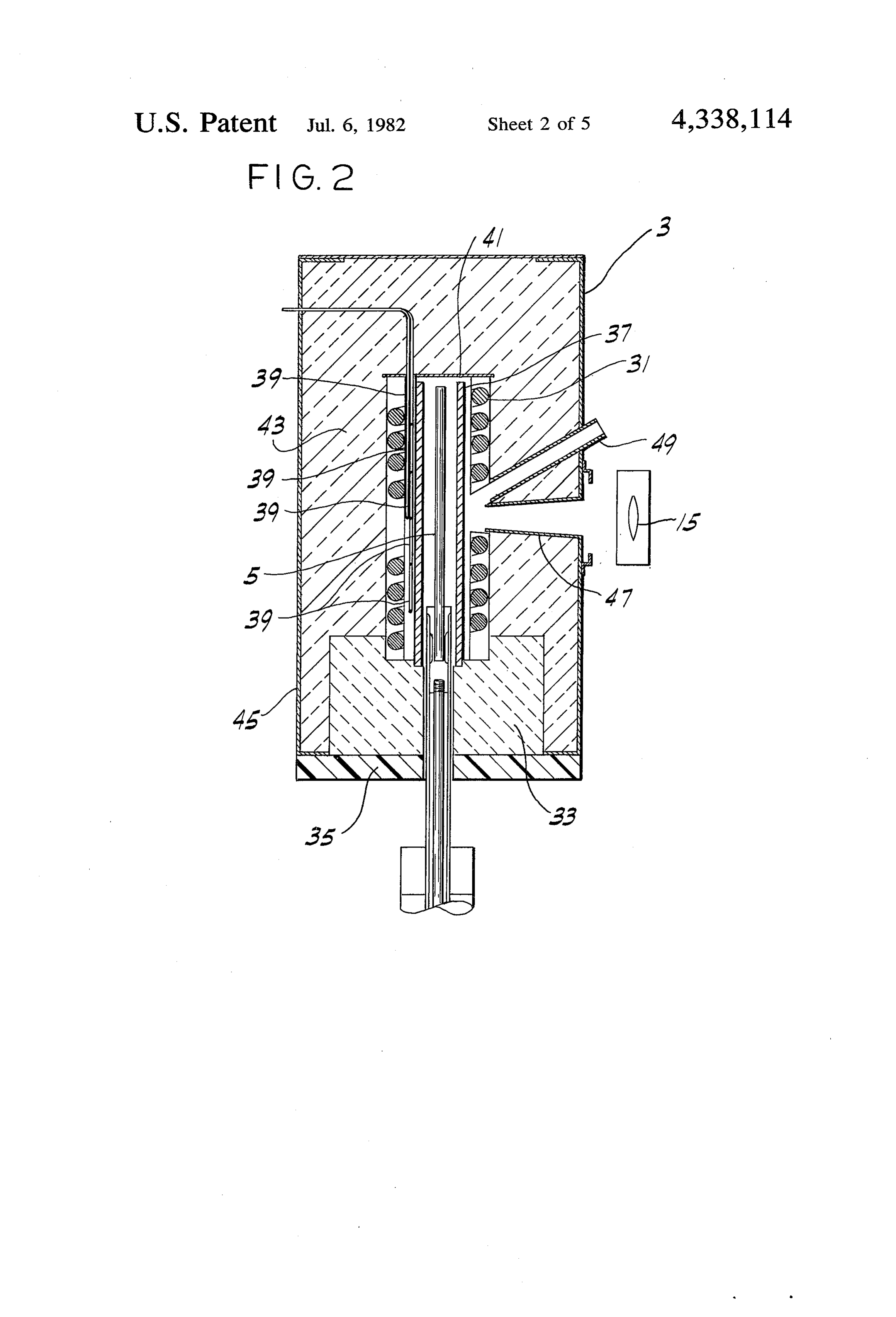
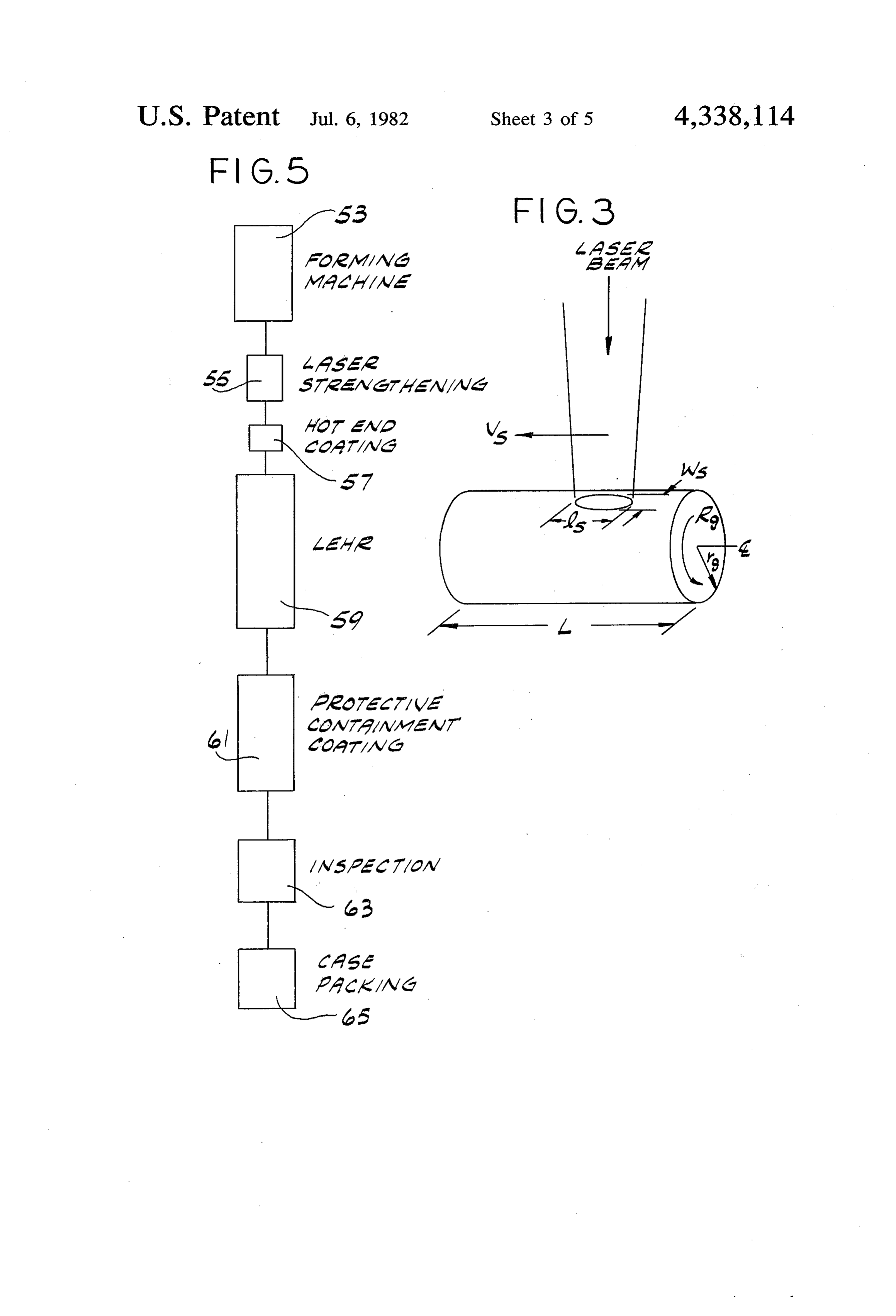
FIG. 1 is a schematic drawing of an apparatus useful 45 as a viscosity of at least about 1013 poise, which is in carrying out the method of the invention; reached at approximately 1000' F. for soda/lime glass. FIG. 2 shows the construction of a furnace useful as As a result of the high energy flux provided by the a part of the apparatus of FIG. 1; laser, rapid localized heating is obtained wherein the FIG. 3 is a schematic drawing illustrating the pro marginal stratum is heated to temperature ranges in cessing geometry utilized in the method of the invention 50 which the glass viscosity is reduced sufficiently to effect where a fixed laser is scanned over a glass object which trastreforming. The utility of this method is in marked con is subjected to simultaneous rotation and translation; to more conventional methods of heating such as, FIG. 4 is a graphic summary of the increase in for example, flame polishing. Although the tempera tures achieved in a flame are high enough to reduce the strength achieved by laser scanning of glass bottles;
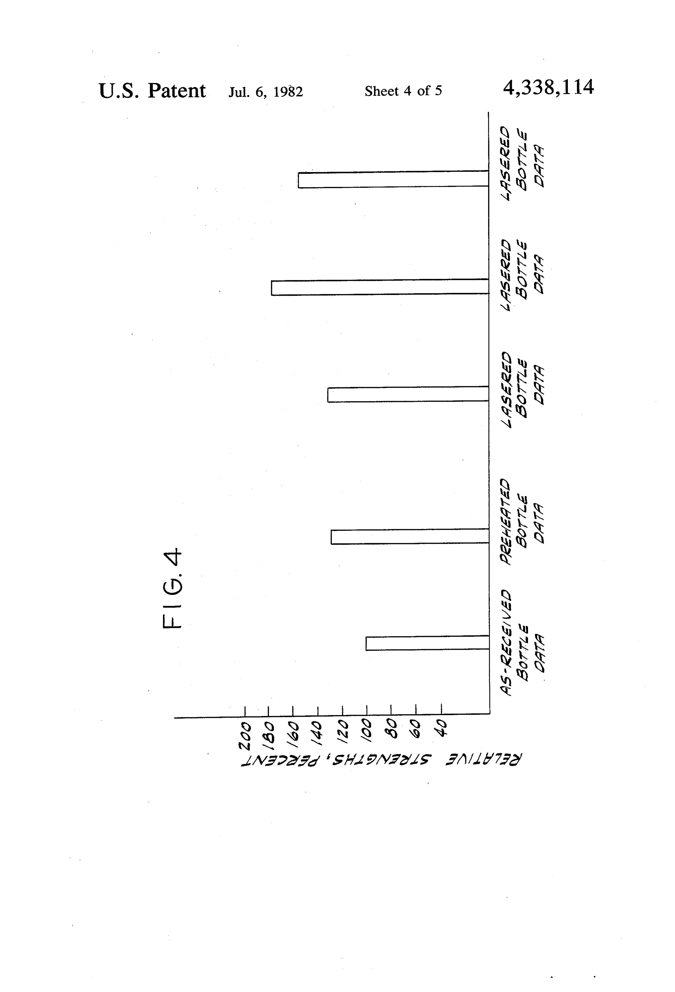
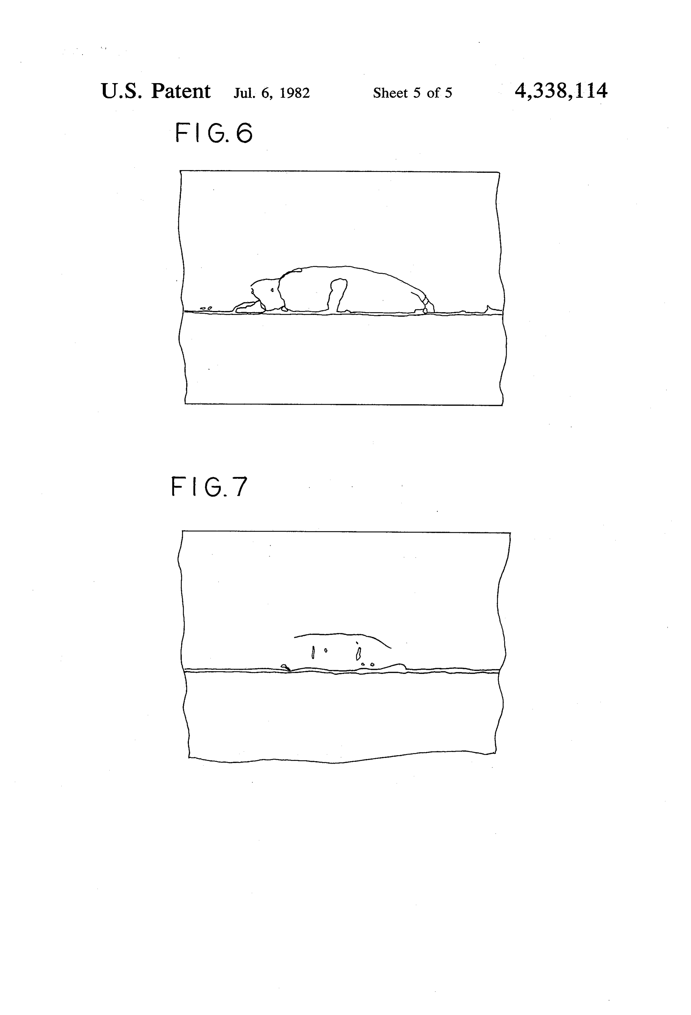
FIG. 5 is a block flow diagram illustrating a preferred 55 glass viscosity, the energy fluxes are not adequate for practical reforming of the imperfections in glass sur alternative for integrating laser strengthening into a faces. Because heat diffusion within the glass occurs at glass bottle manufacturing line; a rate significant by comparison to the heat input at the FIG. 6 is a sketch based on a photomicrograph of a glass surface, heating of a glass surface by flame polish longitudinally diametrically sectioned glass rod and ing is slow, energy consumption supporting plastic oversleeve showing in lateral cross 60 cult to heat the surface stratum toisahigh, and it is diffi temperature range section a crack produced by treatment of the cold rod effective for reforming without heating the bulk of the with a laser beam; and glass object to a temperature at which deformation FIG. 7 is a sketch based on a photomicrograph of the occurs. By contrast, reforming of a glass surface in rod of FIG. 6 showing in lateral cross section the site of accordance with the method of the invention rapidly a similar crack after treatment in accordance with the 65 creates a steep temperature gradient in the surface stra method of the invention. tum of the glass so that flow-inducing viscosities do not Corresponding reference numerals indicate corre extend to a depth of more than about 150 um from the sponding parts in the several views of the drawings. glass surface. Accordingly, the heat absorbed by the
Page 9
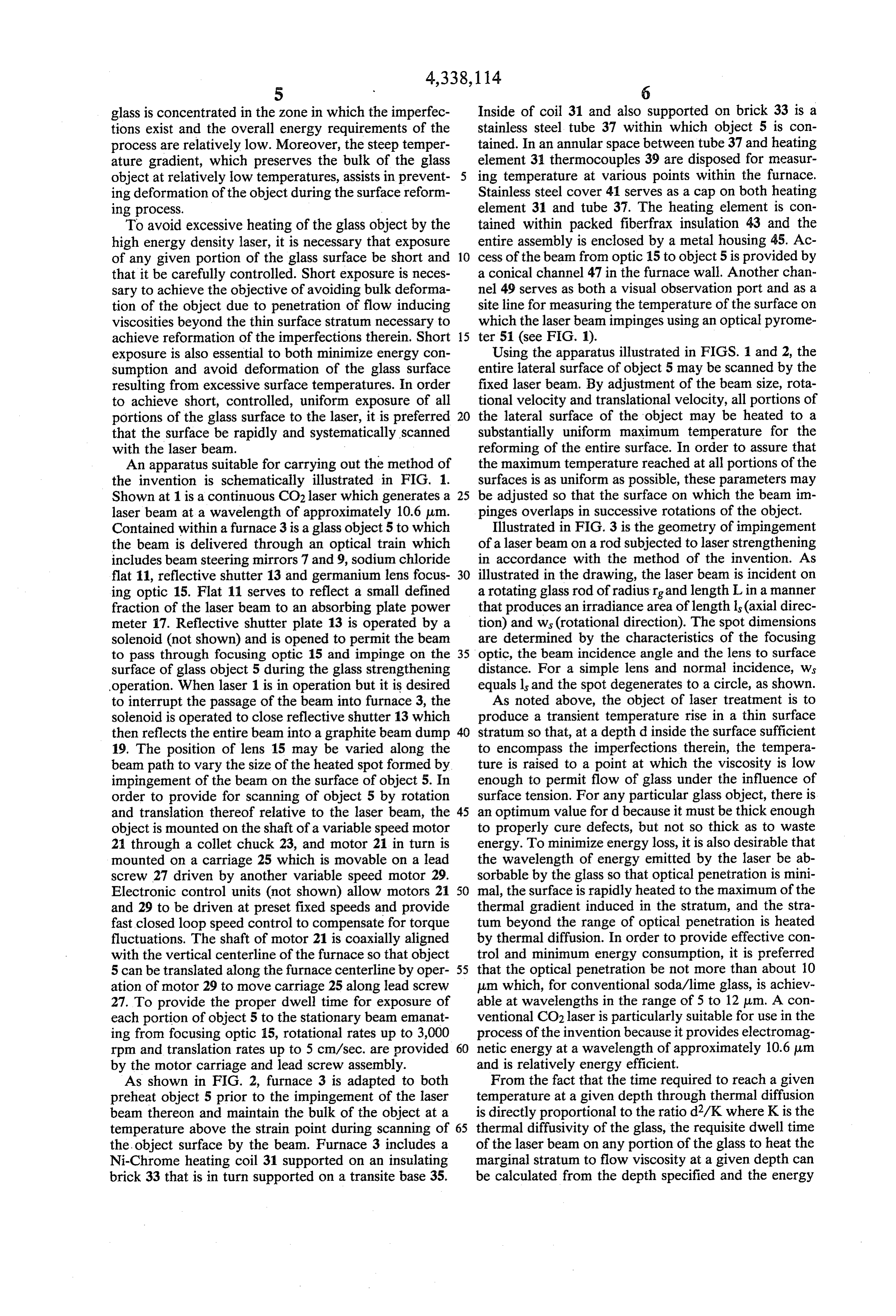
glass is concentrated in the Zone in which the imperfec Inside of coil 31 and also supported on brick 33 is a tions exist and the overall energy requirements of the stainless steel tube 37 within which object 5 is con process are relatively low. Moreover, the steep temper tained. In an annular space between tube 37 and heating ature gradient, which preserves the bulk of the glass element 31 thermocouples 39 are disposed for measur object at relatively low temperatures, assists in prevent ing temperature at various points within the furnace. ing deformation of the object during the surface reform Stainless steel cover 41 serves as a cap on both heating ing process. element 31 and tube 37. The heating element is con To avoid excessive heating of the glass object by the tained within packed fiberfrax insulation 43 and the high energy density laser, it is necessary that exposure entire assembly is enclosed by a metal housing 45. Ac of any given portion of the glass surface be short and 10 cess of the beam from optic 15 to object 5 is provided by that it be carefully controlled. Short exposure is neces a conical channel 47 in the furnace wall. Another chan sary to achieve the objective of avoiding bulk deforma nel 49 serves as both a visual observation port and as a tion of the object due to penetration of flow inducing site line for measuring the temperature of the surface on viscosities beyond the thin surface stratum necessary to which the laser beam impinges using an optical pyrome achieve reformation of the imperfections therein. Short 15 ter 51 (see FIG. 1).
exposure is also essential to both minimize energy con Using the apparatus illustrated in FIGS. 1 and 2, the sumption and avoid deformation of the glass surface entire lateral surface of object 5 may be scanned by the resulting from excessive surface temperatures. In order fixed laser beam. By adjustment of the beam size, rota to achieve short, controlled, uniform exposure of all tional velocity and translational velocity, all portions of portions of the glass surface to the laser, it is preferred 20 the lateral surface of the object may be heated to a that the surface be rapidly and systematically scanned substantially uniform maximum temperature for the with the laser beam. reforming of the entire surface. In order to assure that An apparatus suitable for carrying out the method of the maximum temperature reached at all portions of the the invention is schematically illustrated in FIG. 1. surfaces is as uniform as possible, these parameters may Shown at 1 is a continuous CO2 laser which generates a 25 be adjusted so that the surface on which the beam in laser beam at a wavelength of approximately 10.6 p.m. pinges overlaps in successive rotations of the object. Contained within a furnace 3 is a glass object 5 to which Illustrated in FIG. 3 is the geometry of impingement the beam is delivered through an optical train which of a laser beam on a rod subjected to laser strengthening includes beam steering mirrors 7 and 9, sodium chloride in accordance with the method of the invention. As flat 11, reflective shutter 13 and germanium lens focus 30 illustrated in the drawing, the laser beam is incident on ing optic 15. Flat 11 serves to reflect a small defined a rotating glass rod of radius rg and length L in a manner fraction of the laser beam to an absorbing plate power that produces an irradiance area of length is (axial direc meter 17. Reflective shutter plate 13 is operated by a tion) and ws (rotational direction). The spot dimensions solenoid (not shown) and is opened to permit the beam are determined by the characteristics of the focusing to pass through focusing optic 15 and impinge on the 35 optic, the beam incidence angle and the lens to surface surface of glass object 5 during the glass strengthening distance. For a simple lens and normal incidence, ws operation. When laser 1 is in operation but it is desired equals l and the spot degenerates to a circle, as shown. to interrupt the passage of the beam into furnace 3, the As noted above, the object of laser treatment is to solenoid is operated to close reflective shutter 13 which produce a transient temperature rise in a thin surface then reflects the entire beam into a graphite beam dump 40 stratum so that, at a depth d inside the surface sufficient 19. The position of lens 15 may be varied along the to encompass the imperfections therein, the tempera beam path to vary the size of the heated spot formed by ture is raised to a point at which the viscosity is low impingement of the beam on the surface of object 5. In enough to permit flow of glass under the influence of order to provide for scanning of object 5 by rotation surface tension. For any particular glass object, there is and translation thereof relative to the laser beam, the 45 an optimum value for d because it must be thick enough object is mounted on the shaft of a variable speed motor to properly cure defects, but not so thick as to waste 21 through a collet chuck 23, and motor 21 in turn is energy. To minimize energy loss, it is also desirable that mounted on a carriage 25 which is movable on a lead the wavelength of energy emitted by the laser be ab screw 27 driven by another variable speed motor 29. sorbable by the glass so that optical penetration is mini Electronic control units (not shown) allow motors 21 50 mal, the surface is rapidly heated to the maximum of the and 29 to be driven at preset fixed speeds and provide thermal gradient induced in the stratum, and the stra fast closed loop speed control to compensate for torque tum beyond the range of optical penetration is heated fluctuations. The shaft of motor 21 is coaxially aligned by thermal diffusion. In order to provide effective con with the vertical centerline of the furnace so that object trol and minimum energy consumption, it is preferred 5 can be translated along the furnace centerline by oper 55 that the optical penetration be not more than about 10 ation of motor 29 to move carriage 25 along lead screw um which, for conventional soda/lime glass, is achiev 27. To provide the proper dwell time for exposure of able at wavelengths in the range of 5 to 12 um. A con each portion of object 5 to the stationary beam emanat ventional CO2 laser is particularly suitable for use in the ing from focusing optic 15, rotational rates up to 3,000 process of the invention because it provides electromag rpm and translation rates up to 5 cm/sec. are provided 60 netic energy at a wavelength of approximately 10.6 um by the motor carriage and lead screw assembly. and is relatively energy efficient. As shown in FIG. 2, furnace 3 is adapted to both From the fact that the time required to reach a given preheat object 5 prior to the impingement of the laser temperature at a given depth through thermal diffusion beam thereon and maintain the bulk of the object at a is directly proportional to the ratio d2/K where K is the temperature above the strain point during scanning of 65 thermal diffusivity of the glass, the requisite dwell time the, object surface by the beam. Furnace 3 includes a of the laser beam on any portion of the glass to heat the Ni-Chrome heating coil 31 supported on an insulating marginal stratum to flow viscosity at a given depth can brick 33 that is in turn supported on a transite base 35. be calculated from the depth specified and the energy
Page 10
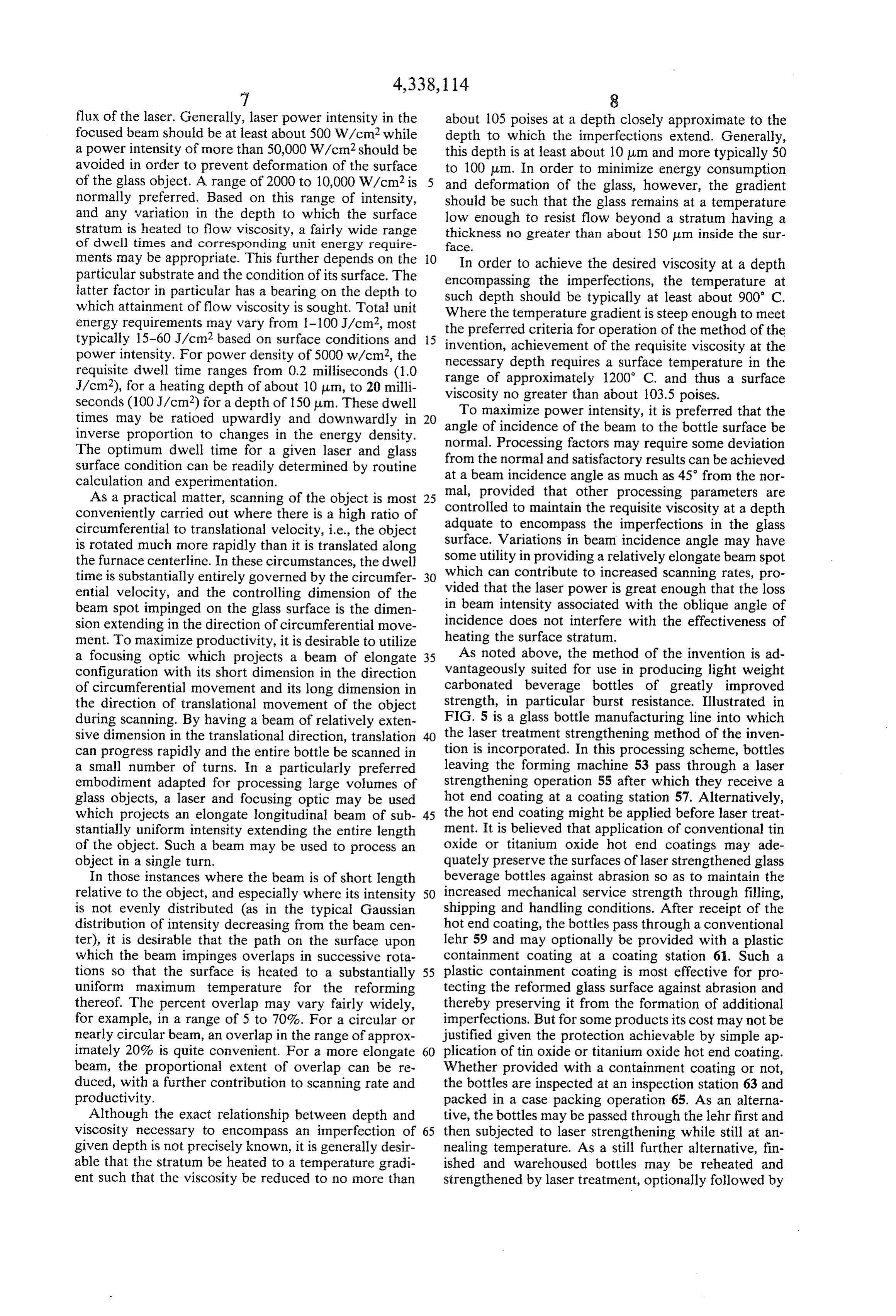
flux of the laser. Generally, laser power intensity in the about 105 poises at a depth closely approximate to the focused beam should be at least about 500 W/cm2 while depth to which the imperfections extend. Generally, a power intensity of more than 50,000 W/cm2 should be this depth is at least about 10 um and more typically 50 avoided in order to prevent deformation of the surface to 100 um. In order to minimize energy consumption of the glass object. A range of 2000 to 10,000 W/cm2 is and deformation of the glass, however, the gradient normally preferred. Based on this range of intensity, should be such that the glass remains at a temperature and any variation in the depth to which the surface low enough to resist flow beyond a stratum having a stratum is heated to flow viscosity, a fairly wide range thickness no greater than about 150 pum inside the sur of dwell times and corresponding unit energy require face.
ments may be appropriate. This further depends on the 10 In order to achieve the desired viscosity at a depth particular substrate and the condition of its surface. The encompassing the imperfections, the temperature at latter factor in particular has a bearing on the depth to which attainment of flow viscosity is sought. Total unit such
Where depth should be typically at least about 900 C.
the temperature gradient is steep enough to meet energy requirements may vary from 1-100 J/cm2, most the preferred criteria for operation of the method of the typically 15-60J/cm2 based on surface conditions and 15 invention, achievement power intensity. For power density of 5000 w/cm2, the necessary depth requiresofathe requisite viscosity at the surface temperature in the requisite dwell time ranges from 0.2 milliseconds (1.0 range of approximately 1200° C. and thus a surface J/cm2), for a heating depth of about 10 um, to 20 milli viscosity no greater than about 103.5 poises. seconds (100 J/cm2) for a depth of 150 um. These dwell To maximize power intensity, it is preferred that the times may be ratioed upwardly and downwardly in 20 angle inverse proportion to changes in the energy density. normal.of Processing incidence of the beam to the bottle surface be
The optimum dwell time for a given laser and glass from the normal andfactors may require some deviation satisfactory results can be achieved surface condition can be readily determined by routine at a beam incidence angle as much as 45 from the nor calculation and experimentation. mal, provided that other processing parameters are As a practical matter, scanning of the object is most 25 controlled conveniently carried out where there is a high ratio of adquate totoencompass maintain the requisite viscosity at a depth the imperfections in the glass circumferential to translational velocity, i.e., the object is rotated much more rapidly than it is translated along surface. Variations in beam incidence angle may have some utility in providing a relatively elongate beam spot the furnace centerline. In these circumstances, the dwell time is substantially entirely governed by the circumfer 30 which can contribute to increased scanning rates, pro ential velocity, and the controlling dimension of the vided that the laser power is great enough that the loss beam spot impinged on the glass surface is the dimen in beam intensity associated with the oblique angle of sion extending in the direction of circumferential move incidence does not interfere with the effectiveness of ment. To maximize productivity, it is desirable to utilize heating the surface stratum. a focusing optic which projects a beam of elongate 35 As noted above, the method of the invention is ad configuration with its short dimension in the direction vantageously suited for use in producing light weight of circumferential movement and its long dimension in carbonated beverage bottles of greatly improved the direction of translational movement of the object strength, in particular burst resistance. Illustrated in during scanning. By having a beam of relatively exten FIG. 5 is a glass bottle manufacturing line into which sive dimension in the translational direction, translation 40 the laser treatment strengthening method of the inven can progress rapidly and the entire bottle be scanned in tion is incorporated. In this processing scheme, bottles a small number of turns. In a particularly preferred leaving the forming machine 53 pass through a laser embodiment adapted for processing large volumes of strengthening operation 55 after which they receive a glass objects, a laser and focusing optic may be used hot end coating at a coating station 57. Alternatively, which projects an elongate longitudinal beam of sub 45 the hot end coating might be applied before laser treat stantially uniform intensity extending the entire length ment. It is believed that application of conventional tin of the object. Such a beam may be used to process an oxide or titanium oxide hot end coatings may ade object in a single turn. quately preserve the surfaces of laser strengthened glass In those instances where the beam is of short length beverage bottles against abrasion so as to maintain the relative to the object, and especially where its intensity 50 increased mechanical service strength through filling, is not evenly distributed (as in the typical Gaussian shipping and handling conditions. After receipt of the distribution of intensity decreasing from the beam cen hot end coating, the bottles pass through a conventional ter), it is desirable that the path on the surface upon lehr 59 and may optionally be provided with a plastic which the beam impinges overlaps in successive rota containment coating at a coating station 61. Such a tions so that the surface is heated to a substantially 55 plastic containment coating is most effective for pro uniform maximum temperature for the reforming tecting the reformed glass surface against abrasion and thereof. The percent overlap may vary fairly widely, thereby preserving it from the formation of additional for example, in a range of 5 to 70%. For a circular or imperfections. But for some products its cost may not be nearly circular beam, an overlap in the range of approx justified given the protection achievable by simple ap imately 20% is quite convenient. For a more elongate 60 plication of tin oxide or titanium oxide hot end coating. beam, the proportional extent of overlap can be re Whether provided with a containment coating or not, duced, with a further contribution to scanning rate and the bottles are inspected at an inspection station 63 and productivity. packed in a case packing operation 65. As an alterna Although the exact relationship between depth and tive, the bottles may be passed through the lehr first and viscosity necessary to encompass an imperfection of 65 then subjected to laser strengthening while still at an given depth is not precisely known, it is generally desir nealing temperature. As a still further alternative, fin able that the stratum be heated to a temperature gradi ished and warehoused bottles may be reheated and ent such that the viscosity be reduced to no more than strengthened by laser treatment, optionally followed by
Page 11
plastic containment coating immediately prior to ship lateral surface of a 5 cm. length of glass had been pro ment. cessed, the laser beam shutter was closed and the glass The following examples illustrate the invention. rod removed for cooling and testing.
In the laser treatment of glass rods, preheat tempera
EXAMPLE 1 5 ture ranged from 1012 to 1021 F. for a time of ten
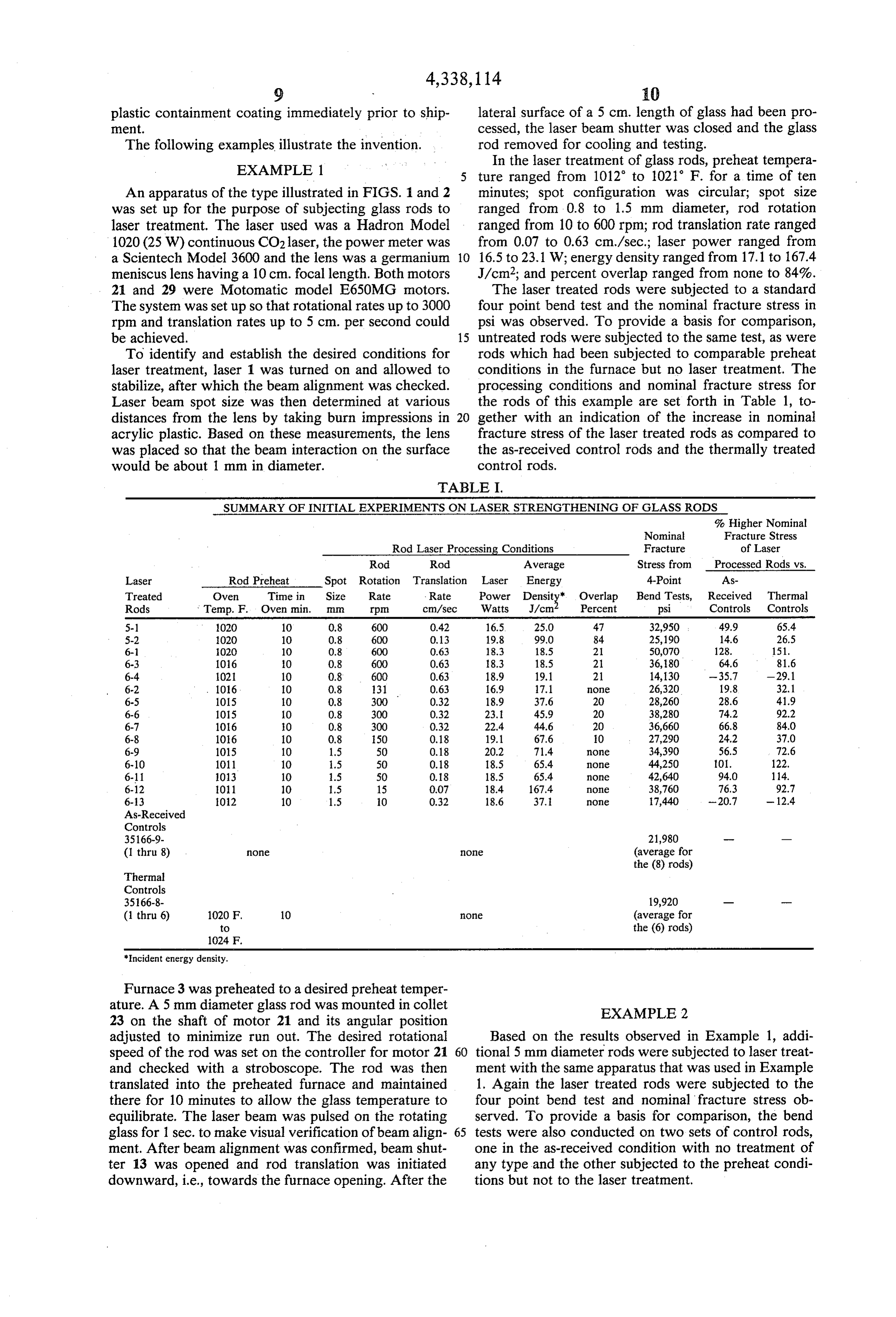
An apparatus of the type illustrated in FIGS. 1 and 2 minutes; spot configuration was circular; spot size was set up for the purpose of subjecting glass rods to ranged from 0.8 to 1.5 mm diameter, rod rotation laser treatment. The laser used was a Hadron Model ranged from 10 to 600 rpm; rod translation rate ranged 1020 (25W) continuous CO2 laser, the power meter was from 0.07 to 0.63 cm/sec.; laser power ranged from a Scientech Model 3600 and the lens was a germanium 10 16.5 to 23.1 W: energy density ranged from 17.1 to 167.4 meniscus lens having a 10 cm. focal length. Both motors J/cm2; and percent overlap ranged from none to 84%. 21 and 29 were Motomatic model E650MG motors. The laser treated rods were subjected to a standard The system was set up so that rotational rates up to 3000 four point bend test and the nominal fracture stress in rpm and translation rates up to 5 cm. per second could psi was observed. To provide a basis for comparison, be achieved. 15 untreated rods were subjected to the same test, as were To identify and establish the desired conditions for rods which had been subjected to comparable preheat laser treatment, laser 1 was turned on and allowed to conditions in the furnace but no laser treatment. The stabilize, after which the beam alignment was checked. processing conditions and nominal fracture stress for Laser beam spot size was then determined at various the rods of this example are set forth in Table 1, to distances from the lens by taking burn impressions in 20 gether with an indication of the increase in nominal acrylic plastic. Based on these measurements, the lens fracture stress of the laser treated rods as compared to was placed so that the beam interaction on the surface the as-received control rods and the thermally treated would be about 1 mm in diameter. control rods.
TABLE I.
SUMMARY OF INITIAL EXPERIMENTS ON LASER STRENGTHENING OF GLASSRODS % Higher Nominal
Nominal Fracture Stress
Rod Laser Processing Conditions Fracture of Laser
Rod Rod Average Stress from Processed Rods vs.
Laser Rod Preheat Spot Rotation Translation Laser Energy 4-Point As Treated Owen Time in Size Rate Rate Power Density Overlap Bend Tests, Received Thermal Rods Temp. F. Oven min. mm rpm cm/sec Watts J/cm Percent psi Controls Controls
S-2 020 10 0.8 600 0.13 19.8 99.0 84 25,190 14.6 26.5 6-1 O2O 10 0.8 600 0.63 18.3 18.5 2 50,070 128. 151. 6-3 1016 O 0.8 600 0.63 18.3 18.5 21 36,80 64.6 81.6 6-4 102 10 0.8 600 0.63 18.9 19.1 21 14, 130 -35.7 -29.1 6-2 1016 O 0.8 31 0.63 16.9 17.1 Ole 26,320 19.8 32.1 6-5 1015 10 0.8 300 0.32 18.9 37.6 20 28,260 28.6 41.9 6-6 105 10 0.8 300 0.32 23. 45.9 20 38,280 74.2 92.2 6-7 1016 O 0.8 300 O.32 22.4 44.6 20 36,660 66.8 840 6-8 106 O 0.8 50 0,18 19.1 67.6 O 27,290 24.2 37.0 6-9 105 10 1.5 50 0.18 20.2 71.4 Oe 34,390 56.5 T2.6 6-10 1011 10 1.5 50 0.18 18.5 65.4 e 44,250 101. 122, 6-11 1013 10 1.5 50 0.18 18.5 65.4 none 42,640 94.0 114. 6-12 011 10 1.5 15 0.07 18.4 167.4 Ole 38,760 76.3 92.7 6-3 O2 10 1.5 O 0.32 18.6 37. Ole 17,440 -20.7 - 12.4
Controls 35166-9- 21,980 (1 thru 8) One Oe (average for the (8) rods)
Thermal
Controls 35166-8- 19,920 ---- (1 thru 6) 1020 F. 10 One (average for to the (6) rods)
Incident energy density.
Furnace 3 was preheated to a desired preheat temper ature. A 5 mm diameter glass rod was mounted in collet EXAMPLE 2 23 on the shaft of motor 21 and its angular position adjusted to minimize run out. The desired rotational Based on the results observed in Example 1, addi speed of the rod was set on the controller for motor 21 60 tional 5 mm diameter rods were subjected to laser treat and checked with a stroboscope. The rod was then ment with the same apparatus that was used in Example translated into the preheated furnace and maintained 1. Again the laser treated rods were subjected to the there for 10 minutes to allow the glass temperature to four point bend test and nominal fracture stress ob equilibrate. The laser beam was pulsed on the rotating served. To provide a basis for comparison, the bend glass for 1 sec. to make visual verification of beam align 65 tests were also conducted on two sets of control rods, ment. After beam alignment was confirmed, beam shut one in the as-received condition with no treatment of ter 13 was opened and rod translation was initiated any type and the other subjected to the preheat condi downward, i.e., towards the furnace opening. After the tions but not to the laser treatment.
Page 12
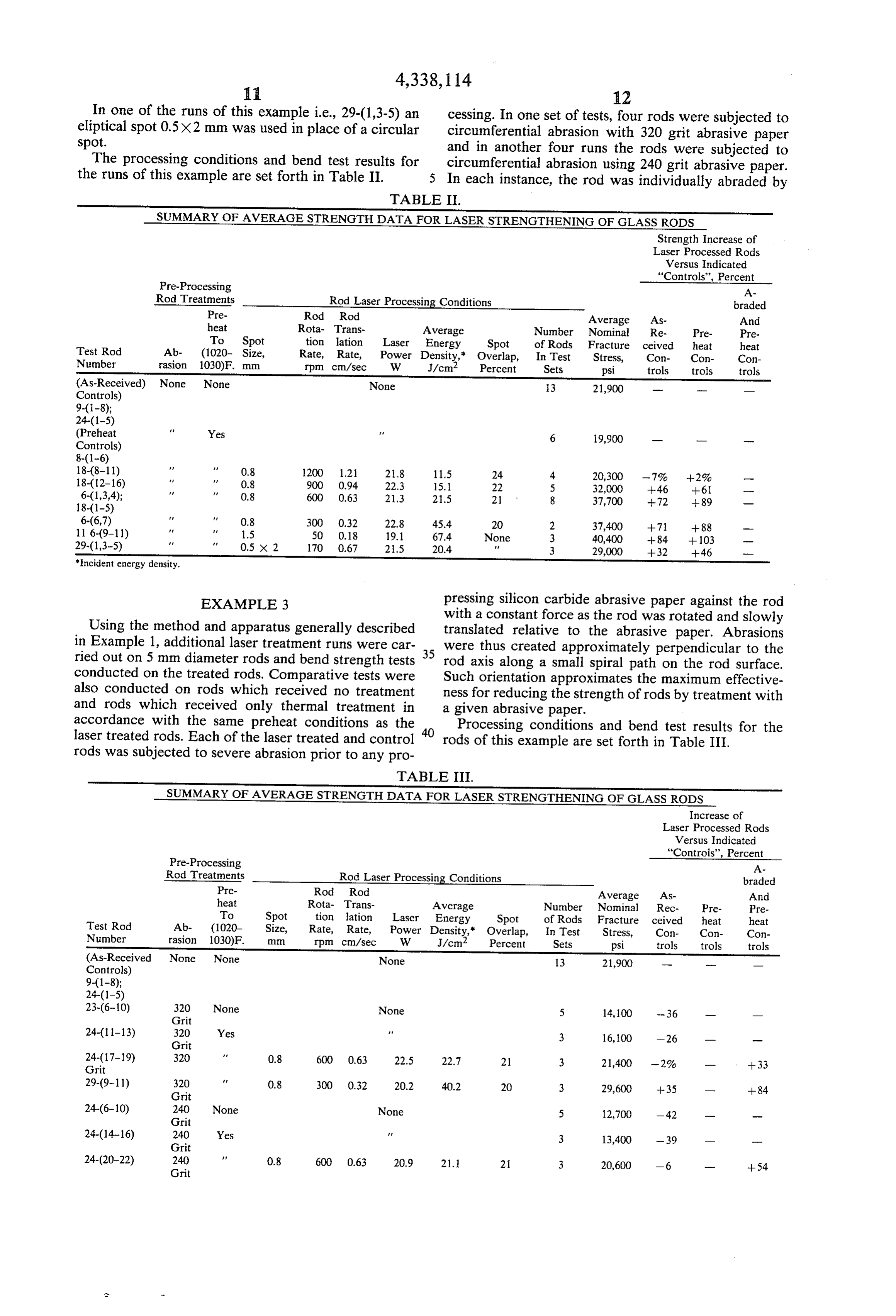
In one of the runs of this example i.e., 29-(1,3-5) an cessing. In one set of tests, four rods were subjected to eliptical spot 0.5X2 mm was used in place of a circularcircumferential abrasion with 320 grit abrasive paper spot. and in another four runs the rods were subjected to
The processing conditions and bend test results for circumferential abrasion using 240 grit abrasive paper.
the runs of this example are set forth in Table II. 5 In each instance, the rod was individually abraded by
TABLE II.
SUMMARY OF AVERAGE STRENGTH DATA FOR LASER STRENGTHENING OF GLASSRODS
Strength Increase of
Laser Processed Rods
Versus Indicated
"Controls', Percent
Pre-Processing A Rod Treatments Rod Laser Processing Conditions braded Pre- Rod Rod Average As- And heat Rota- Trans- Average Number Nominal Re- Pre- Pre To Spot tion lation Laser Energy Spot of Rods Fracture ceived heat heat Test Rod Ab- (1020- Size, Rate, Rate, Power Density," Overlap, In Test Stress, Con- Con- Con Number rasion 1030)F. mm rpm cm/sec W J/cm2 Percent Sets psi trols trols trols (As-Received) None None None 3 21,900 - - - Controls)
(Preheat Yes f 6 19,900 - - --- Controls)
18-(8-11) t 0.8 1200 1.21 21.8 11.5 24 4. 20,300 - 7%. --2% - 18-(12-16) Ft. 0.8 900 0.94 22.3 15. 22 5 32,000 -- 46 --61 --- 6-(1,3,4); O.8 600 0.63 21.3 21.5 21 8 37,700 --72 --89 -
6-(6,7) Ff 0.8 300 0.32 22.8 45.4 20 2 37,400 -- 71 --88 11 6-(9–11) f 1.5 50 0.18 19.1 67.4 None 3 40,400 --84 - 103 -- 29-(1,3-5) f 0.5 X 2 170 0.67 2.5 20.4 3 29,000 --32 - 46 Incident energy density.
EXAMPLE 3 pressing silicon carbide abrasive paper against the rod with a constant force as the rod was rotated and slowly
Using the method and apparatus generally described translated relative to the abrasive paper. Abrasions in Example 1, additional laser treatment runs were car 35 were thus created approximately perpendicular to the ried out on 5 mm diameter rods and bend strength tests rod axis along a small spiral path on the rod surface.
conducted on the treated rods. Comparative tests were Such orientation approximates the maximum effective also conducted on rods which received no treatment ness for reducing the strength of rods by treatment with and rods which received only thermal treatment in a given abrasive paper.
accordance with the same preheat conditions as the 40 Processing conditions and bend test results for the laser treated rods. Each of the laser treated and control rods of this example are set forth in Table III.
rods was subjected to severe abrasion prior to any pro
TABLE III.
SUMMARY OF AVERAGE STRENGTH DATA FOR LASER STRENGTHENING OF GLASSRODS
Increase of
Laser Processed Rods
Versus Indicated
"Controls', Percent
Pre-Processing A Rod Treatments Rod Laser Processing Conditions braded Pre- Rod Rod Average As- And heat Rota- Trans- Average Number Nominal Rec- Pre- Pre To Spot tion lationLaser Energy Spot of Rods Fracture ceived heat heat Test Rod Ab- (1020- Size, Rate, Rate, Power Density," Overlap, In Test Stress, Con- Con- Con Number rasion 1030).F. rpm cm/sec W J/cm2 Percent Sets psi trols trols trols (As-Received None None None 13 21,900 -- - Controls)
23-(6-10) 320 None None 5 14,100 -36 - - Grit 24-(11-13) 320 Yes 3 16,100 -26 - - Grit 24-(17-19) 320 0.8 600 0.63 22.5 22.7 21 3 21,400 -2% - - -33 Grit 29-(9-11) 320 0.8 300 0.32 20.2 40.2 20 3 29,600 --35 -- --84 Grit 24-(6-10) 240 None None 5 12,700 - 42 - - Grit 24-(14-16) 240 Yes w 3 13,400 -39 - - Grit 24-(20-22) 240 0.8 600 0.63 20.9 21. 21 3 20,600 -6 -- --54 Grit
Page 13
TABLE III.-continued
SUMMARY OF AVERAGE STRENGTH DATA FOR LASER STRENGTHENING OF GLASS RODS
Increase of
Laser Processed Rods
Versus Indicated
"Controls', Percent
Pre-Processing A Rod Treatments Rod Laser Processing Conditions braded Pre- Rod Rod Average As- And heat Rota- Trans- Average Number Nominal Rec- Pre- Pre To Spot tion lationLaser Energy Spot of Rods Fracture ceived heat heat Test Rod Ab- (1020- Size, Rate, Rate, Power Density," Overlap, In Test Stress, Con- Con- Con Number rasion 1030)F. rpm cm/sec W J/cm2 Percent Sets psi trols trols trols 29-(12-14) 240 AA 0.8 300 0.32 23.5 46.8 20 3 24,000 - 10 - -79 Grit *Incident energy density.
After subjection to preheating and laser treatment the
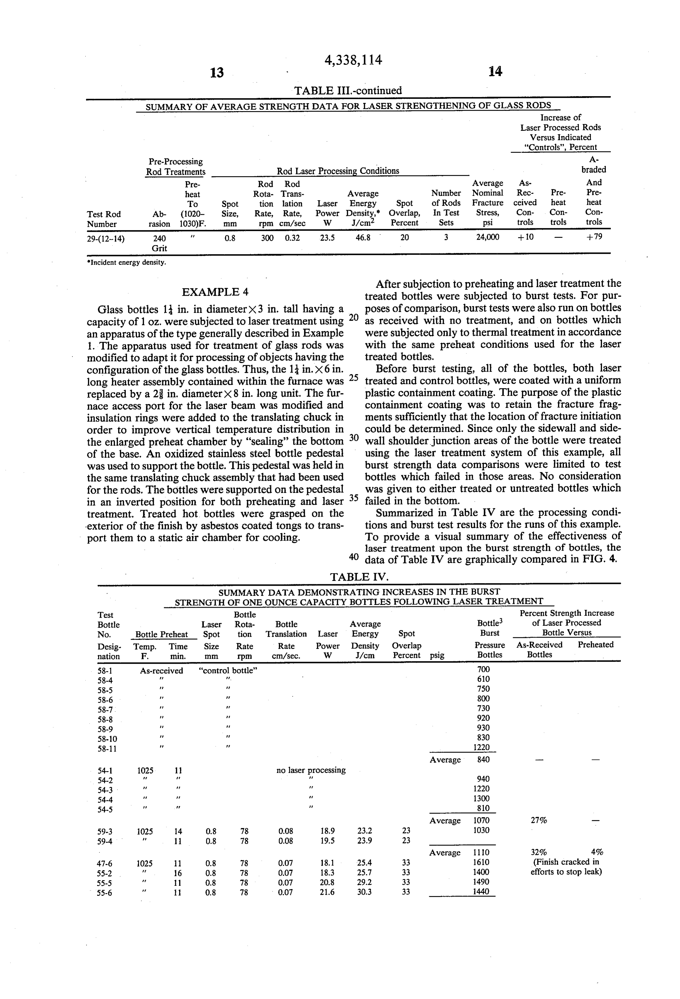
EXAMPLE 4 treated bottles were subjected to burst tests. For pur
Glass bottles 1 in. in diameterx3 in. tall having a poses of comparison, burst tests were also run on bottles capacity of 1 oz. were subjected to laser treatment using 20 as received with no treatment, and on bottles which an apparatus of the type generally described in Example were subjected only to thermal treatment in accordance 1. The apparatus used for treatment of glass rods was with the same preheat conditions used for the laser modified to adapt it for processing of objects having the treated bottles.
configuration of the glass bottles. Thus, the 13 in.X6 in. Before burst testing, all of the bottles, both laser long heater assembly contained within the furnace was treated and control bottles, were coated with a uniform replaced by a 2 in. diameter X8 in. long unit. The fur- plastic containment coating. The purpose of the plastic nace access port for the laser beam was modified and containment coating was to retain the fracture frag insulation rings were added to the translating chuck in ments sufficiently that the location of fracture initiation order to improve vertical temperature distribution in could be determined. Since only the sidewall and side the enlarged preheat chamber by "sealing” the bottom 30 wall shoulder junction areas of the bottle were treated of the base. An oxidized stainless steel bottle pedestal using the laser treatment system of this example, all was used to support the bottle. This pedestal was held in burst strength data comparisons were limited to test the same translating chuck assembly that had been used bottles which failed in those areas. No consideration for the rods. The bottles were supported on the pedestal was given to either treated or untreated bottles which in an inverted position for both preheating and laser failed in the bottom.
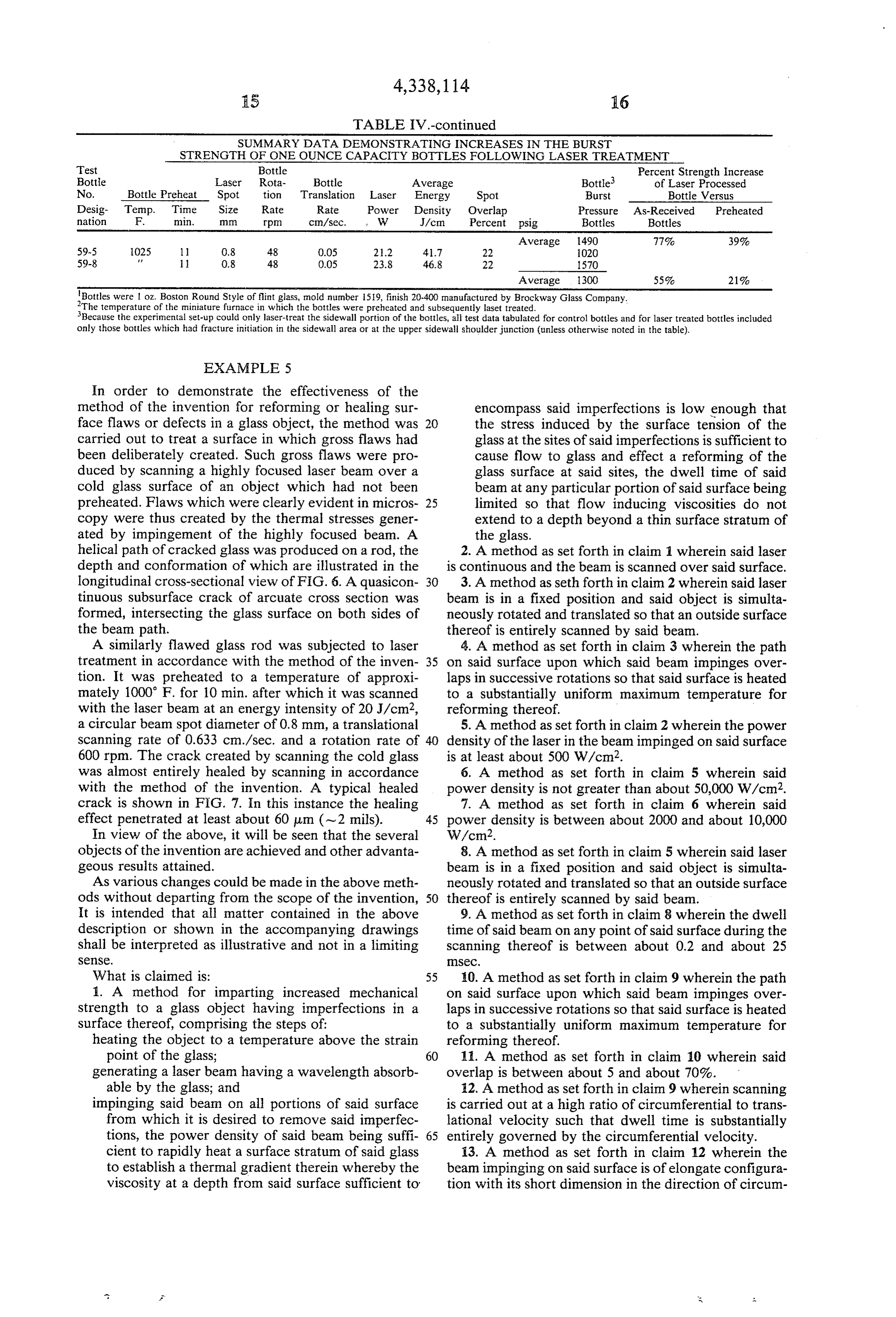
treatment. Treated hot, bottles were grasped on the Summarized in Table IV are the processing condi exterior of the finish by asbestos coated tongs to trans- tions and burst test results for the runs of this example. port them to a static air chamber for cooling. To provide a visual summary of the effectiveness of laser treatment upon the burst strength of bottles, the 0 data of Table IV are graphically compared in FIG. 4.
TABLE IV.
SUMMARY DATA DEMONSTRATING INCREASES IN THE BURST
STRENGTH OF ONE OUNCE CAPACITY BOTTLES FOLLOWING LASER TREATMENT
Test Bottle Percent Strength Increase Bottle Laser Rota- Bottle Average Bottle of Laser Processed No. Bottle Preheat Spot tion Translation Laser Energy Spot Burst Bottle Versus Desig- Temp. Time Size Rate Rate Power Density Overlap Pressure As-Received Preheated nation F. min. rpm cm/sec. W J/cm Percent psig Bottles Bottles 58-1 As-received "control bottle' 700 58-4 v. 610 58-5 750 58-6 800 58-7 730 58-8 920 58-9 930 58-10 830 58-11 1220
54-1 1025 11 no laser processing 54-2 FF A. 940 54-3 FF 1220 54-4 FA 1300 54-5 810
59-4 11 0.8 78 0.08 19.5 23.9 23
47-6 1025 11 0.8 78 0.07 18.1 25.4 33 1610 (Finish cracked in 55-2 f 16 0.8 78 0.07 18.3 25.7 33 1400 efforts to stop leak) 55-5 Af 11 0.8 78 0.07 20.8 29.2 33 490 55-6 FA 0.8 78 0.07 21.6 30.3 33 1440
Page 14
TABLE IV.-continued
SUMMARY DATA DEMONSTRATING INCREASES IN THE BURST
STRENGTH OF ONE OUNCE CAPACITY BOTTLES FOLLOWING LASER TREATMENT
Test Bottle Percent Strength Increase Bottle Laser Rota- Bottle Average Bottle of Laser Processed No. Bottle Preheat Spot tion Translation Laser Energy Spot Burst Bottle Versus Desig- Temp. Time Size Rate Rate Power Density Overlap Pressure As-Received Preheated nation F. min. I rpm cm/sec. , W J/cm Percent psig Bottles Bottles
59-5 1025 11 O.8 48 0.05 21.2 41.7 22 1020 59-8 1. 0.8 48 0.05 23.8 46.8 22 570
Bottles were 1 oz. Boston Round Style of flint glass, mold number 1519, finish 20-400 manufactured by Brockway Glass Company. The temperature of the niniature furnace in which the bottles were preheated and subsequently laset treated. Because the experimental set-up could only laser-treat the sidewall portion of the bottles, all test data tabulated for control bottles and for laser treated bottles included only those bottles which had fracture initiation in the sidewall area or at the upper sidewall shoulder junction (unless otherwise noted in the table).
EXAMPLE 5
In order to demonstrate the effectiveness of the method of the invention for reforming or healing sur encompass said imperfections is low enough that face flaws or defects in a glass object, the method was 20 the stress induced by the surface tension of the carried out to treat a surface in which gross flaws had glass at the sites of said imperfections is sufficient to been deliberately created. Such gross flaws were pro cause flow to glass and effect a reforming of the duced by scanning a highly focused laser beam over a glass surface at said sites, the dwell time of said cold glass surface of an object which had not been beam at any particular portion of said surface being preheated. Flaws which were clearly evident in micros 25 limited so that flow inducing viscosities do not copy were thus created by the thermal stresses gener extend to a depth beyond a thin surface stratum of ated by impingement of the highly focused beam. A the glass.
helical path of cracked glass was produced on a rod, the 2. A method as set forth in claim 1 wherein said laser depth and conformation of which are illustrated in the is continuous and the beam is scanned over said surface. longitudinal cross-sectional view of FIG. 6. A quasicon 30 3. A method asseth forth in claim 2 wherein said laser tinuous subsurface crack of arcuate cross section was beam is in a fixed position and said object is simulta formed, intersecting the glass surface on both sides of neously rotated and translated so that an outside surface the beam path. thereof is entirely scanned by said beam. A similarly flawed glass rod was subjected to laser 4. A method as set forth in claim 3 wherein the path treatment in accordance with the method of the inven 35 on said surface upon which said beam impinges over tion. It was preheated to a temperature of approxi laps in successive rotations so that said surface is heated mately 1000 F. for 10 min. after which it was scanned to a substantially uniform maximum temperature for with the laser beam at an energy intensity of 20 J/cm2, reforming thereof.
a circular beam spot diameter of 0.8 mm, a translational 5. A method as set forth in claim 2 wherein the power scanning rate of 0.633 cm./sec. and a rotation rate of 40 density of the laser in the beam impinged on said surface 600 rpm. The crack created by scanning the cold glass is at least about 500 W/cm2. was almost entirely healed by scanning in accordance 6. A method as set forth in claim 5 wherein said with the method of the invention. A typical healed power density is not greater than about 50,000 W/cm2. crack is shown in FiG. 7. in this instance the healing 7. A method as set forth in claim 6 wherein said effect penetrated at least about 60 um (~2 mils). 45 power density is between about 2000 and about 10,000 In view of the above, it will be seen that the several W/cm2.
objects of the invention are achieved and other advanta 8. A method as set forth in claim 5 wherein said laser geous results attained. beam is in a fixed position and said object is simulta As various changes could be made in the above meth neously rotated and translated so that an outside surface ods without departing from the scope of the invention, 50 thereof is entirely scanned by said beam. It is intended that all matter contained in the above 9. A method as set forth in claim 8 wherein the dwell description or shown in the accompanying drawings time of said beam on any point of said surface during the shall be interpreted as illustrative and not in a limiting scanning thereof is between about 0.2 and about 25 SeSe. SeC.
What is claimed is: 55 10. A method as set forth in claim 9 wherein the path i. A method for imparting increased mechanical on said surface upon which said beam impinges over strength to a glass object having imperfections in a laps in successive rotations so that said surface is heated surface thereof, comprising the steps of: to a substantially uniform maximum temperature for heating the object to a temperature above the strain reforming thereof.
point of the glass; 60 11. A method as set forth in claim 10 wherein said generating a laser beam having a wavelength absorb overlap is between about 5 and about 70%.
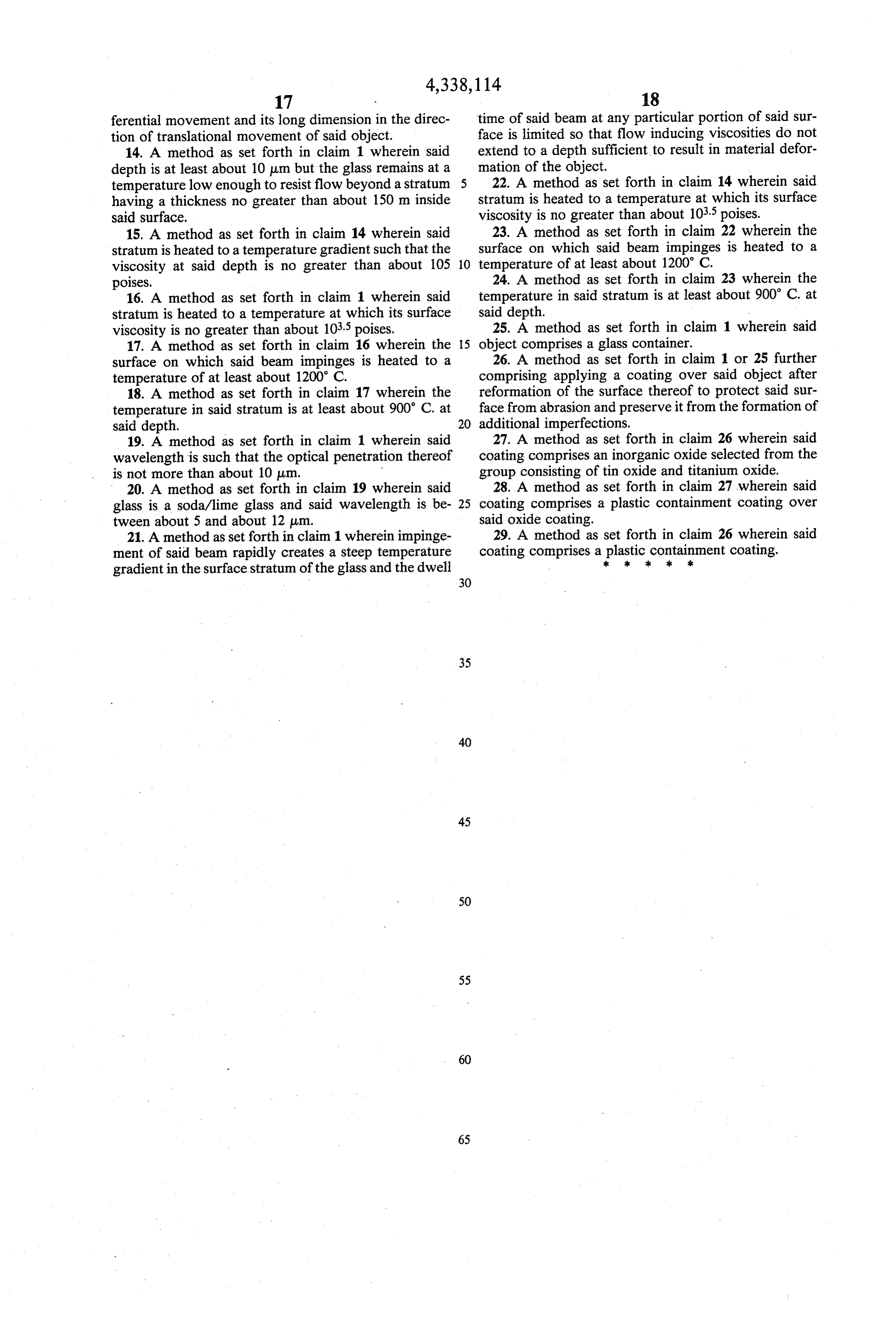
able by the glass; and 12. A method as set forth in claim 9 wherein scanning impinging said beam on all portions of said surface is carried out at a high ratio of circumferential to trans from which it is desired to remove said imperfec lational velocity such that dwell time is substantially tions, the power density of said beam being suffi 65 entirely governed by the circumferential velocity. cient to rapidly heat a surface stratum of said glass 13. A method as set forth in claim 12 wherein the to establish a thermal gradient therein whereby the beam impinging on said surface is of elongate configura viscosity at a depth from said surface sufficient to tion with its short dimension in the direction of circum
Page 15
ferential movement and its long dimension in the direc time of said beam at any particular portion of said sur tion of translational movement of said object. face is limited so that flow inducing viscosities do not 14. A method as set forth in claim 1 wherein said extend to a depth sufficient to result in material defor depth is at least about 10 um but the glass remains at a mation of the object.
temperature low enough to resist flow beyond a stratum 5 22. A method as set forth in claim 14 wherein said having a thickness no greater than about 150 m inside stratum is heated to a temperature at which its surface said surface. viscosity is no greater than about 103.5 poises. 15. A method as set forth in claim 14 wherein said 23. A method as set forth in claim 22 wherein the stratum is heated to a temperature gradient such that the surface on which said beam impinges is heated to a viscosity at said depth is no greater than about 105 10 temperature of at least about 1200° C. poises. 24. A method as set forth in claim 23 wherein the 16. A method as set forth in claim 1 wherein said temperature in said stratum is at least about 900 C. at stratum is heated to a temperature at which its surface said depth.
viscosity is no greater than about 103.5 poises. 25. A method as set forth in claim 1 wherein said 17. A method as set forth in claim 16 wherein the 15 object comprises a glass container.
surface on which said beam impinges is heated to a 26. A method as set forth in claim 1 or 25 further temperature of at least about 1200° C. comprising applying a coating over said object after 18. A method as set forth in claim 17 wherein the reformation of the surface thereof to protect said sur temperature in said stratum is at least about 900' C. at face from abrasion and preserve it from the formation of said depth. 20 additional imperfections.
19. A method as set forth in claim 1 wherein said 27. A method as set forth in claim 26 wherein said wavelength is such that the optical penetration thereof coating comprises an inorganic oxide selected from the is not more than about 10 um. group consisting of tin oxide and titanium oxide. 20. A method as set forth in claim 19 wherein said 28. A method as set forth in claim 27 wherein said glass is a soda/lime glass and said wavelength is be 25 coating comprises a plastic containment coating over tween about 5 and about 12 um. said oxide coating.
21. A method as set forth in claim 1 wherein impinge 29. A method as set forth in claim 26 wherein said ment of said beam rapidly creates a steep temperature coating comprises a 2kplasticsk 2k containment
coating.
gradient in the surface stratum of the glass and the dwell
Provenance
- Collection
- Cited prior art
- Original PDF
- patentimages.storage.googleapis.com →
- Filed
- 1980-08-21
- Pages
- 15
- Method
- pdftotext (the PDF's own text layer) + pdftoppm 300dpi page scans
- Source
- Google Patents bibliographic record
- Granted
- 1982-07-06
- Inventors
- M. Clifford Brockway; Craig T. Walters; Liberty Glass Co
- Transcribed from
- patentimages.storage.googleapis.com →