patent · US6066187
Solar reduction of CO2
23 May 2000
Page 1 — bibliographic record
United States Patent (19) 11 Patent Number: 6,066,187 Jensen et al. (45) Date of Patent: May 23, 2000 54). SOLAR REDUCTION OF CO, J. W. Rablais et al., Chem. Rev. 71, 73(1971). 75 Inventors: Reed J. Jensen, 121 La Vista Dr., Los D. E. Shemansky, J. Chem. Phys. 56, 1582 (1972). Alamos, N.Mex. 87544; John L. M. Koshi et al., Chem. Phys. Lett. 176,519 (1991). Lyman, Los Alamos, N.Mex.; Joe D.
King, Los Alamos, N.Mex.; Robert D. N. A. Generalov et al., Opt. Spectrosc. 15, 12 (1963). Guettler, Los Alamos, N.Mex.
73 Assignee: Reed J. Jensen, Los Alamos, N.Mex. C. Cossart-Magos et al., Mol. Phys. 75, 835 (1992). 21 Appl. No.: 09/034,873 K.L. Coulson, Solar and Terrestrial Radiation: Methods and
Measurements, Academic Press, New York (1975), p. 40.
Related U.S. Application Data Primary Examiner Marian C. Knode 60 Provisional application No. 60/038,576, Mar. 4, 1997. ASSistant Examiner Alexa A. Doroshenk (51) Int. Cl." ................................. C10J 3/20; B01J 19/08 Attorney, Agent, or Firm Samuel M. Freund 52 U.S. Cl. .................. 48/85; 422/186; 422/186.3 57 ABSTRACT 58 Field of Search ................................. 422/186, 186.3;
252/373; 423/418.2; 48/85, 197 The red shift of the absorption spectrum of CO with increasing temperature permits the use of Sunlight to pho 56) References Cited tolyze CO to CO. The process of the present invention
preheated CO to Sunlight, whereby CO, O, and O are 4,062,348 12/1977 Morrison ................................. 126/714 produced; and cooling the hot product mix by rapid admix 4,064,024 12/1977 Lee ........... ... 204/157.44 4,405.594 9/1983 Pyle ........................................ 423/579 ture with room temperature CO2. The excess thermal energy may be used to produce electricity and to heat additional
OTHER PUBLICATIONS CO for Subsequent process steps. The product CO may be B.R. Lewis and J.H. Carver, in J. Quant. Spectrosc. Radiat. used to generate H2 by the shift reaction or to Synthesize methanol.
K. Yoshino et al., in J. Quant Spectrose. Radiat. Transfer 55, 53 (1996). 10 Claims, 5 Drawing Sheets
Cool CO2
COPlenum
S3 Cool CO2 as Ninjection
Radiation, To Pump ugly
Funnel Support and
CO injector Vanes, 36
Solar
Radiation,
Page 2
Drawing sheet — no readable text.
Page 3
Drawing sheet — no readable text.
Page 4
Drawing sheet — no readable text.
Page 5
Drawing sheet — no readable text.
Page 6
Drawing sheet — no readable text.
Page 7
SOLAR REDUCTION OF CO, in Opt. Spectrosc. 15, 12 (1963) measured the absorption of CO behind a shock wave at temperatures as high as 6300
This application claims the benefit of U.S. Provisional K for wavelengths of 238 and 300 nm. Absorption out to 355 Application No. 60/038,576 Filing Date Mar. 4, 1997. nm at 5000 K was observed. Although the reported data are This invention was made with government Support under not precise, an increase of absorption with temperature is indicated. CroSS Sections and error estimates were derived
Contract No. W-7405-ENG-36 awarded by the U.S. Depart by the present inventors from the data at 1523 K, 1818 K, ment of Energy to The Regents of the University of Cali 2073 K, and 2273 K. The results for 2273 K are shown as fornia. The government has certain rights in the invention. triangles in FIG. 1.
FIELD OF THE INVENTION The Visible emission Seen by many in carbon monoxide/ oxygen flames is evidence that transitions exist for CO2 to
The present invention relates generally to the red shift in absorb visible and near ultraviolet light if the molecule is the ultraviolet absorption spectrum of CO into the blue end heated sufficiently. This emission has been studied between of the Solar spectrum with increasing temperature and, more 310 and 380 nm in R. N. Dixon, Proc. Roy. Soc. 275, 431 particularly, to the use of this effect for the direct Solar 15 (1963), and the conclusion was drawn that it came from reduction of CO2 for removing and recycling this atmo transitions between the bent B state of CO to highly Spheric greenhouse gas. excited vibrational states of the electronic ("X") ground BACKGROUND OF THE INVENTION State. Thermal population of the highly excited vibrational States at high temperatures should allow absorption, the
Present reserves of fossil fuel result from the storage of reverse of this emission process, to occur. To reach the ancient Solar energy as chemical energy. AS these reserves absorption transitions observed by Dixon, Supra, in emission are combusted, the attendant growth in the atmospheric and would require vibrational energy in excess of 1.88 eV. At oceanic reservoirs of CO2 contributes to the greenhouse room temperature, the fraction of molecules with more than effect. There has been a general recognition of the need for 1.88 eV is 7x10. However, that fraction is 1.3x10" at an efficient process to assist natural processes in photo 25 1523 Kand 8.8x10 at 2273 K. Transitions to the 'A state chemically removing CO2, while Storing Solar energy. may also contribute to absorption by CO. C. CoSSart-Magos Ongoing developments in Solar fuels involve either biologi et al., in Mol. Phys. 75,835 (1992) have attributed nine weak cal processes or hydrogen production from water Splitting. bands between 175 and 200 nm to transitions to that state. No known research addresses the problem directly through Similar transitions from vibrationally excited States could the physical and Spectral properties of CO2. It has been contribute to the absorption spectrum at longer wavelengths noted in the literature that CO has no spectral absorption in and elevated temperatures.
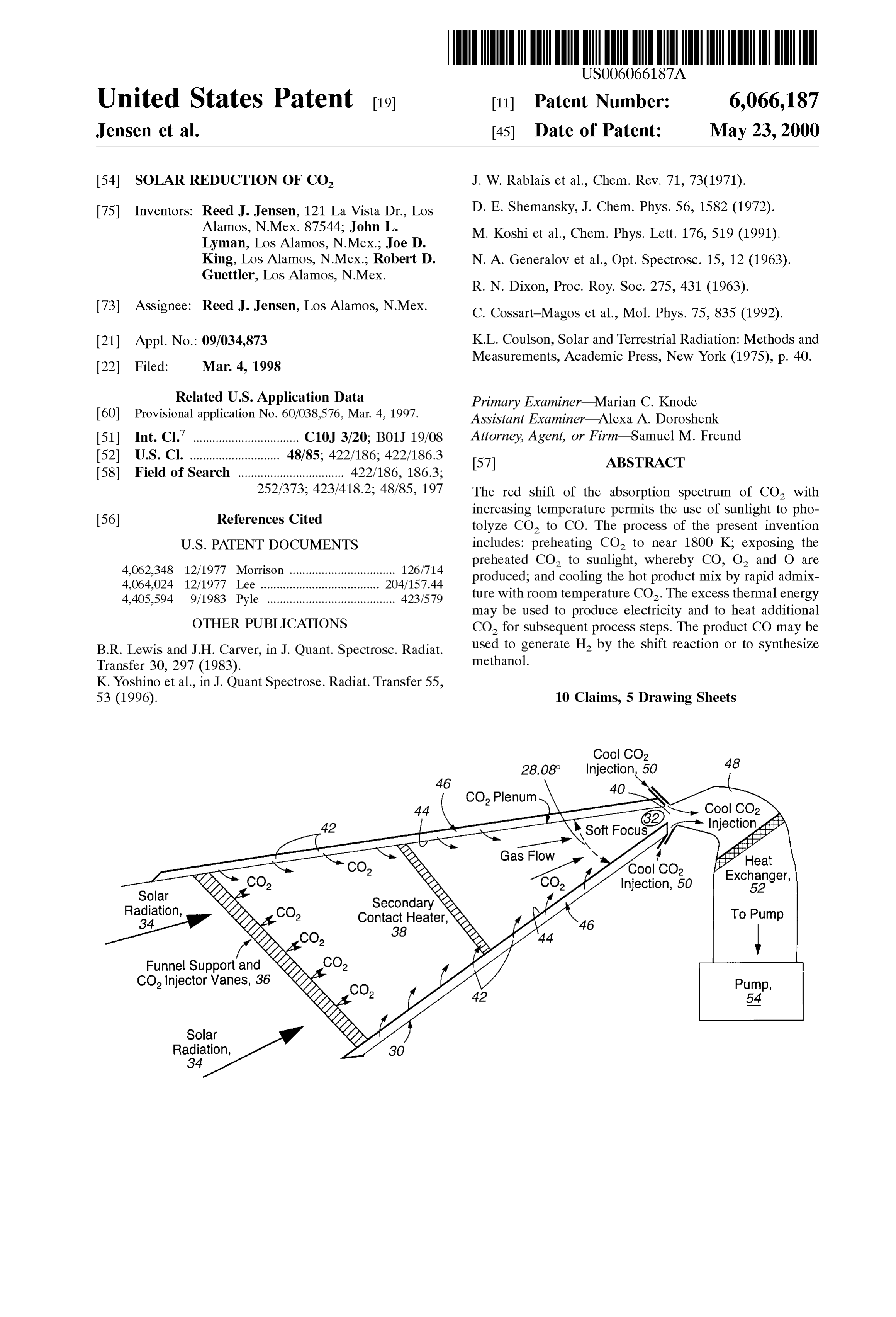
the Visible or near-ultraViolet portion of the Spectrum under Direct Solar reduction of CO would require significant normal circumstances, therefore, direct photoreduction of absorption cross section beyond 300 nm as is illustrated in CO has appeared to be unlikely and has received little FIG. 1, where a portion of the solar irradiance at the earth's attention. 35 Surface taken from Solar and Terrestrial Radiation. Methods FIG. 1 hereof, labeled prior art, shows existing measure and Measurements by K. L. Coulson, Academic Press, New ments of the temperature dependence of the CO absorption York (1975), p. 40, is shown. spectrum. The dotted and solid curves were reported by B. Accordingly, it is an object of the present invention to R. Lewis and J. H. Carver, in J. Quant. Spectrosc. Radiat. provide a process for the direct Solar reduction of CO2 to Transfer 30, 297 (1983), at 202 and 367 K, respectively. 40 CO.
Some temperature dependence was observed throughout the Another object of the present invention is to provide a entire spectral range, but the greatest effect was at longer process for generating CO and hydrogen for liquid fuel wavelengths. The absorption croSS Sections were found to production from CO in the ambient atmosphere. increase with temperature at about 1.5%/K at the long Additional objects, advantages and novel features of the wavelength limit of these data sets (197 nm). K. Yoshino et 45 invention will be set forth in part in the description which al., in J. Quant Spectrosc. Radiat. Transfer 55, 53 (1996), follows, and in part will become apparent to those skilled in measured the same spectrum at two temperatures (195 Kand the art upon examination of the following or may be learned 295 K) between 120 and 175 nm. Their results were nearly by practice of the invention. The objects and advantages of identical to those of Lewis and Carver, Supra. These results the invention may be realized and attained by means of the Suggest that Substantial enhancement of absorption croSS 50 instrumentalities and combinations particularly pointed out Section may be expected at longer wavelengths and elevated in the appended claims.
temperatures. The spectrum published by J. W. Rablais et al.
in Chem. Rev. 71, 73 (1971) and the measurement of D. E. SUMMARY OF THE INVENTION Shemansky in J. Chem. Phys. 56,1582 (1972) agree with the To achieve the foregoing and other objects, and in accor room temperature data of Lewis and Carver, Supra, in the 55 dance with the purposes of the present invention, as embod region of Overlap. Shemansky, Supra, extended the measure ied and broadly described herein, the method for generating ment out to 300 nm where extinction by Rayleigh scattering carbon monoxide from carbon dioxide hereof includes: interfered with observation of the very weak absorption. heating flowing carbon dioxide to a temperature Such that M. Koshi et al. in Chem. Phys. Lett. 176, 519 (1991) absorption of the Solar spectrum occurs, exposing the heated reported a dramatic increase in the absorption of CO2 with 60 carbon dioxide to Solar radiation whereby Substantial disso temperature between 1500 and 3000 K. The absorption cross ciation of the carbon dioxide to carbon monoxide takes sections at 193 nm were inferred in shock-heated CO by place, forming thereby a hot gas mixture, and cooling the hot measuring the atomic oxygen produced by photolysis of gas mixture Sufficiently rapidly to Stabilize the carbon mon CO. The determination of absorption croSS Sections oxide.
assumed a unity photolysis quantum yield to O(P) atoms. 65 Benefits and advantages of the present invention include Measurements at 1520 K and 2850 K are also shown in FIG. the preparation of liquid fuel while removing an important 1 as circles and Squares, respectively. N. A. Generalov et al. greenhouse gas from the atmosphere.
Page 8
BRIEF DESCRIPTION OF THE DRAWINGS however, the back-flow of CO into the insert through the The accompanying drawings, which are incorporated in center Slits was minimized. The furnace was operated under Steady-state flow conditions. Along with gas flow into the and form a part of the Specification, illustrate an embodiment window ports, a Small amount of gas, 24, was introduced of the present invention and, together with the description, through a Secondary inlet to regulate the total cell pressure. Serve to explain the principles of the invention. In the An adjustable flow to a Source of vacuum, 26, is the only gas drawings: outlet. Cell pressures were nominally maintained at about FIG. 1 shows prior art absorption cross sections for CO 300 torr.
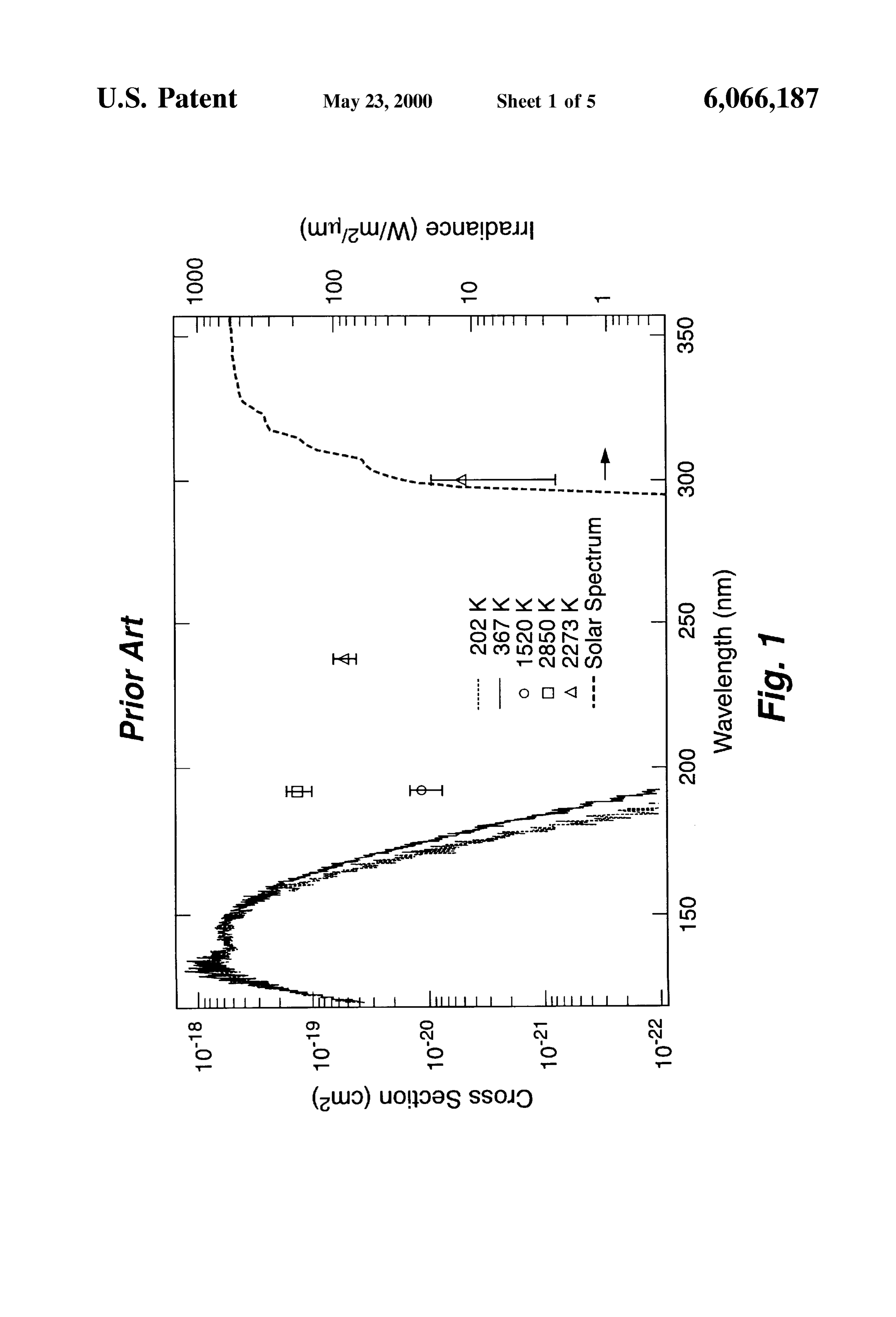
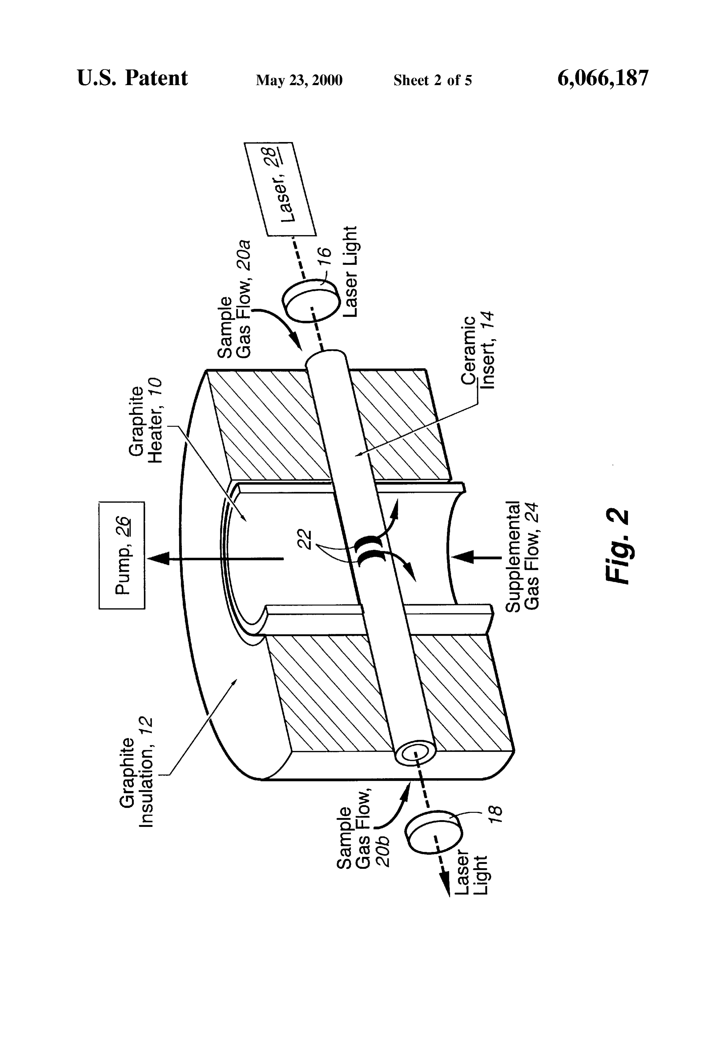
as a function of wavelength at various temperatures. The The gas composition inside the ceramic insert was deter Solar irradiance (dashed line, right axis) is also shown. mined by taking gas Samples at Several points along the FIG. 2 is a Schematic representation of a heated cell in length of the insert at 1808 K. Mass spectrometric analyses which the absorption measurements for CO of the present of these samples showed that the CO fraction along the observation path varied from 83 to 94%. Carbon monoxide invention were performed. was the primary constituent in the remaining fraction. The FIG. 3 shows absorption cross sections for CO derived CO partial pressure was taken to be 90% of the total cell from measurements using the apparatus shown in FIG. 2 preSSure for all of the experimental data presented.
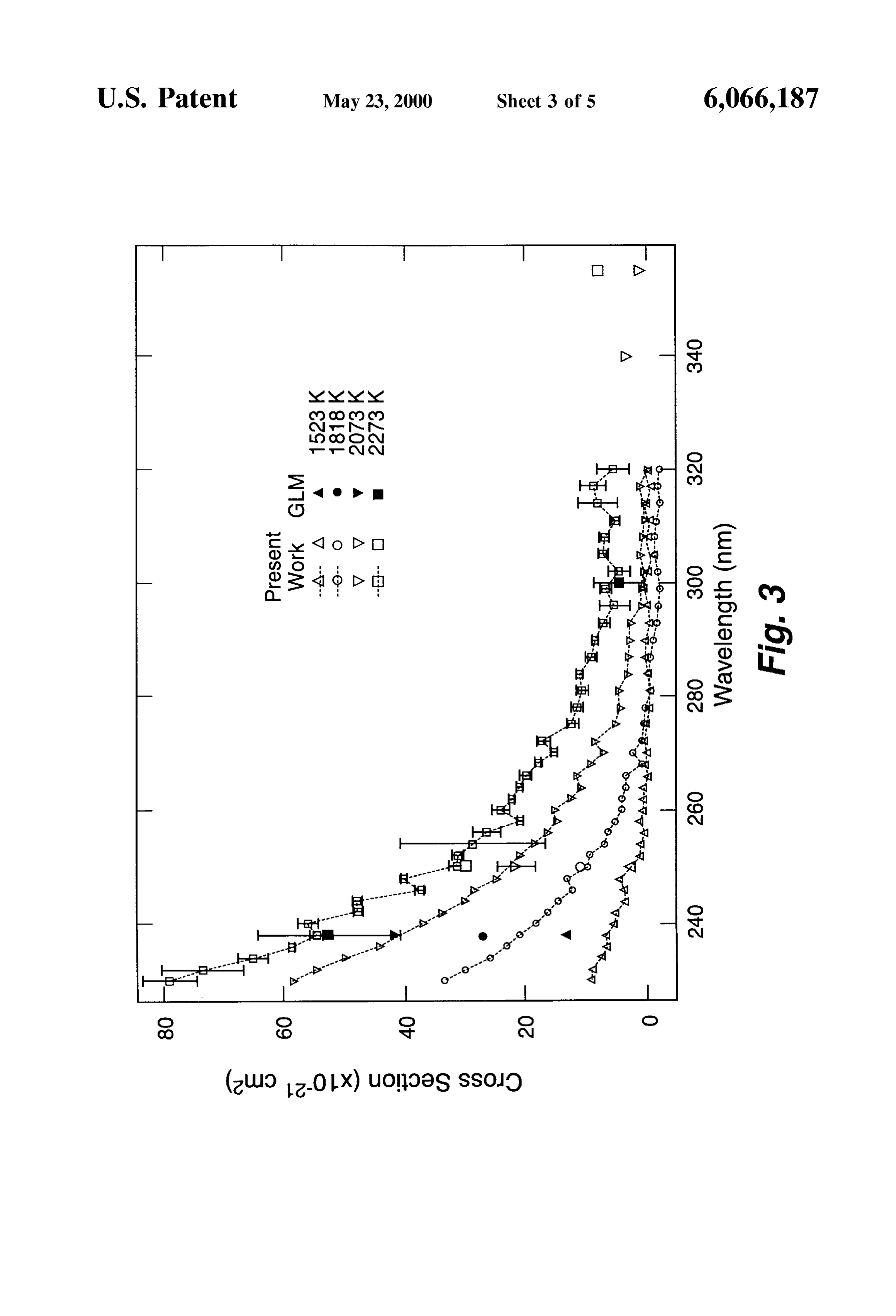
hereof. The entrance and exit windows of the optical path were FIGS. 4a and 4b are schematic illustrations of the side Separated by approximately 36 cm. The graphite heater planar View and the top planar View, respectively, of a Solar element was at the center and directly heated approximately funnel for demonstrating the method of the present 6 cm of this path length. In the 15-cm distance between the invention, where Solar irradiance and hot CO are concen window and the heater element, the temperature rose from trated into a reaction plenum Such that the CO2 is exposed room temperature to the furnace operating temperature. The to a Soft focus of Solar radiation. gas temperature down the length of this tube was measured, FIG. 5 is a schematic illustration of the injection of cool providing an experimental temperature profile. This tem perature profile complicated the assignment of an experi
CO into the hot reaction gases generated by the funnel 25 mental path length and gas density, as will be discussed shown in FIG. 4 hereof in such a manner that strong more fully hereinbelow.
turbulent mixing rapidly cools the gases by reaction and The transmission Spectra were measured using the tunable dilution. ultraViolet output of a laser apparatus, 28, which produces DETAILED DESCRIPTION pulses at 10 Hz through a substantial portion of the visible and ultraViolet regions. The pulse energies ranged between
Briefly, the present invention includes the extension of the 0.2 and 0.5 m.J with spectral widths between 6 and 30 cm Spectral absorption croSS Sections from the ultraViolet into and a temporal width of 10 ns. In the temperature range of the Solar region of the spectrum for hot CO. Such absorp interest, 1523 to 2273 K, absorption measurements require tion either produces direct dissociation of CO into CO+O or a probe beam that is significantly brighter than the thermal raises the temperature of the gas, thereby increasing thermal 35 background radiation. The laser Source employed provided dissociation. The dissociation products can then be used to ample brightness for these measurements. The incident and create Synthesis gas (CO+H) for the production of liquid transmitted energies were measured for each laser shot. Ten fuels. Thus, the proposed proceSS reduces combustion CO2 laser shots were averaged by a radiometer, which was read emissions, closes the carbon fuel cycle, and creates a class three times for each wavelength. The scan reproducibility of of Solar fuel products. 40 the laser system is believed to be the major contributor to the Reference will now be made in detail to the present noise in the measured data. The CO2 absorption spectra were embodiment of the invention, an example of which is determined by first filling the hot cell with helium and illustrated in the accompanying drawings. In order to gen measuring the background transmission spectrum over the erate the absorption croSS Sections required to demonstrate desired range, typically 230 to 344 nm. The cell was then the method of the present invention and to go beyond the 45 evacuated to s10 torr, filled with CO, and the transmission transient shock environment of Generalov et al., Supra, Spectrum of the CO measured. The cell was again carbon dioxide was heated in a commercial electrical evacuated, filled with helium, and another background trans furnace, a Schematic representation of which is shown in mission spectrum was measured. Whenever possible, the FIG. 2 hereof. Resistive heater element, 10, and insulation, Sample transmission Spectrum was corrected with the aver 12, of the furnace were both constructed out of graphite. At 50 age of the before and after background measurements. high temperatures, however, CO will react with graphite to A more Sensitive method was used to measure the CO make CO. At temperatures above 1500 K the CO, CO, and transmission at Selected wavelengths. With the laser wave graphite equilibrium strongly favors CO (CO:CO<1:1000). length fixed and the cell initially filled with helium, the To minimize the loss of CO in this apparatus, an yttria transmission was continuously measured at intervals of ceramic insert, 14, was used to assist in the isolation of the 55 approximately 3 S. While monitoring the transmission, the CO2 from the hot graphite furnace elements. The insert cell was evacuated and filled with CO. After allowing the connects the optical path entrance and exit windows, 16 and transmission to Stabilize, the cell was evacuated and again 18, respectively. Sample gas, 20a and 20b, was introduced filled with helium. Several data points from these absorption into the furnace at the window ports where it flows acroSS curves were averaged to determine the background and the inside window Surfaces. The gas then flows down the 60 Sample transmission and, with these averages, the Sample length of the tube and out through slits, 22, near the center. transmission was corrected for the background. These The ceramic insert limits the operating temperature of the absorption “step’ Scans have significantly better Sensitivity apparatus to 2273 K, at which temperature the insert showed than the laser Scan methods described above, providing Signs of fracture and loSS of rigidity. Because the hot absorption sensitivity down to 0.003, or approximately graphite readily reduces CO to CO, the environment out 65 5x10° cm cross section. This limit is somewhat wave Side the ceramic insert is almost entirely CO. By maintaining length dependent and primarily results from pointing insta a constant positive flow rate of CO into the ceramic insert, bilities in the laser System.
Page 9
S 6
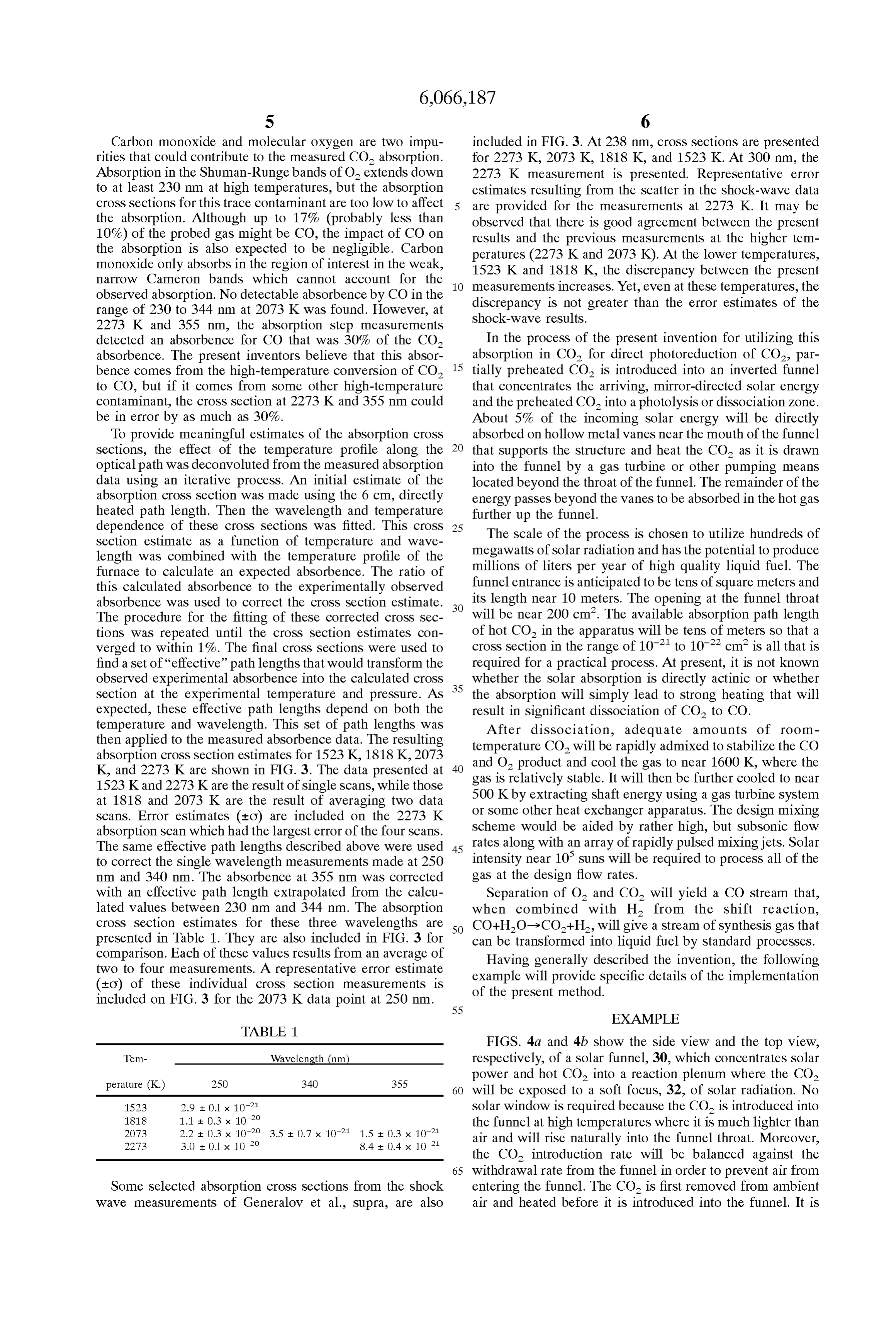
Carbon monoxide and molecular oxygen are two impu included in FIG. 3. At 238 nm, cross sections are presented rities that could contribute to the measured CO absorption. for 2273 K, 2073 K, 1818 K, and 1523 K. At 300 nm, the Absorption in the Shuman-Runge bands of O extends down 2273 K measurement is presented. Representative error to at least 230 nm at high temperatures, but the absorption estimates resulting from the Scatter in the Shock-wave data croSS Sections for this trace contaminant are too low to affect are provided for the measurements at 2273 K. It may be the absorption. Although up to 17% (probably less than observed that there is good agreement between the present 10%) of the probed gas might be CO, the impact of CO on results and the previous measurements at the higher tem the absorption is also expected to be negligible. Carbon peratures (2273 K and 2073 K). At the lower temperatures, monoxide only absorbs in the region of interest in the weak, 1523 K and 1818 K, the discrepancy between the present narrow Cameron bands which cannot account for the observed absorption. No detectable absorbence by CO in the measurements increases. Yet, even at these temperatures, the discrepancy is not greater than the error estimates of the range of 230 to 344 nm at 2073 K was found. However, at Shock-wave results.
2273 K and 355 nm, the absorption step measurements detected an absorbence for CO that was 30% of the CO In the process of the present invention for utilizing this absorbence. The present inventors believe that this absor 15 absorption in CO for direct photoreduction of CO2, par bence comes from the high-temperature conversion of CO tially preheated CO is introduced into an inverted funnel to CO, but if it comes from Some other high-temperature that concentrates the arriving, mirror-directed Solar energy contaminant, the cross section at 2273 K and 355 nm could and the preheated CO into a photolysis or dissociation Zone. be in error by as much as 30%. About 5% of the incoming Solar energy will be directly To provide meaningful estimates of the absorption croSS absorbed on hollow metal vanes near the mouth of the funnel Sections, the effect of the temperature profile along the that Supports the Structure and heat the CO as it is drawn optical path was deconvoluted from the measured absorption into the funnel by a gas turbine or other pumping means data using an iterative process. An initial estimate of the located beyond the throat of the funnel. The remainder of the absorption croSS Section was made using the 6 cm, directly energy passes beyond the Vanes to be absorbed in the hot gas heated path length. Then the wavelength and temperature further up the funnel.
dependence of these croSS Sections was fitted. This croSS 25 The Scale of the process is chosen to utilize hundreds of Section estimate as a function of temperature and wave megawatts of Solar radiation and has the potential to produce length was combined with the temperature profile of the millions of liters per year of high quality liquid fuel. The furnace to calculate an expected absorbence. The ratio of this calculated absorbence to the experimentally observed funnel entrance is anticipated to be tens of Square meters and absorbence was used to correct the croSS Section estimate. its length near 10 meters. The opening at the funnel throat The procedure for the fitting of these corrected croSS Sec will be near 200 cm. The available absorption path length tions was repeated until the croSS Section estimates con of hot CO in the apparatus will be tens of meters so that a verged to within 1%. The final cross sections were used to cross section in the range of 10° to 10° cm is all that is find a set of “effective” path lengths that would transform the required for a practical process. At present, it is not known observed experimental absorbence into the calculated croSS 35 whether the Solar absorption is directly actinic or whether Section at the experimental temperature and pressure. AS the absorption will Simply lead to Strong heating that will expected, these effective path lengths depend on both the result in Significant dissociation of CO2 to CO. temperature and wavelength. This set of path lengths was After dissociation, adequate amounts of room then applied to the measured absorbence data. The resulting temperature CO will be rapidly admixed to stabilize the CO absorption cross section estimates for 1523 K, 1818 K, 2073 and O2 product
K, and 2273 K are shown in FIG. 3. The data presented at 40 gas is relatively and cool the gas to near 1600 K, where the stable. It will then be further cooled to near 1523 Kand 2273 Kare the result of single scans, while those 500 K by extracting shaft energy using a gas turbine System at 1818 and 2073 K are the result of averaging two data scans. Error estimates (to) are included on the 2273 K or Some other heat eXchanger apparatus. The design mixing absorption Scan which had the largest error of the four Scans. scheme would be aided by rather high, but subsonic flow The same effective path lengths described above were used 45 rates along with an array of rapidly pulsed mixing jets. Solar to correct the Single wavelength measurements made at 250 intensity near 10 Suns will be required to process all of the nm and 340 nm. The absorbence at 355 nm was corrected gas at the design flow rates.
with an effective path length extrapolated from the calcu Separation of O and CO will yield a CO stream that, lated values between 230 nm and 344 nm. The absorption when combined with H from the shift reaction, croSS Section estimates for these three wavelengths are 50 CO+HO->CO+H, will give a stream of synthesis gas that presented in Table 1. They are also included in FIG. 3 for can be transformed into liquid fuel by Standard processes. comparison. Each of these values results from an average of Having generally described the invention, the following two to four measurements. A representative error estimate example will provide Specific details of the implementation (EO) of these individual cross Section measurements is of the present method.
included on FIG. 3 for the 2073 K data point at 250 nm. 55
EXAMPLE
TABLE 1.
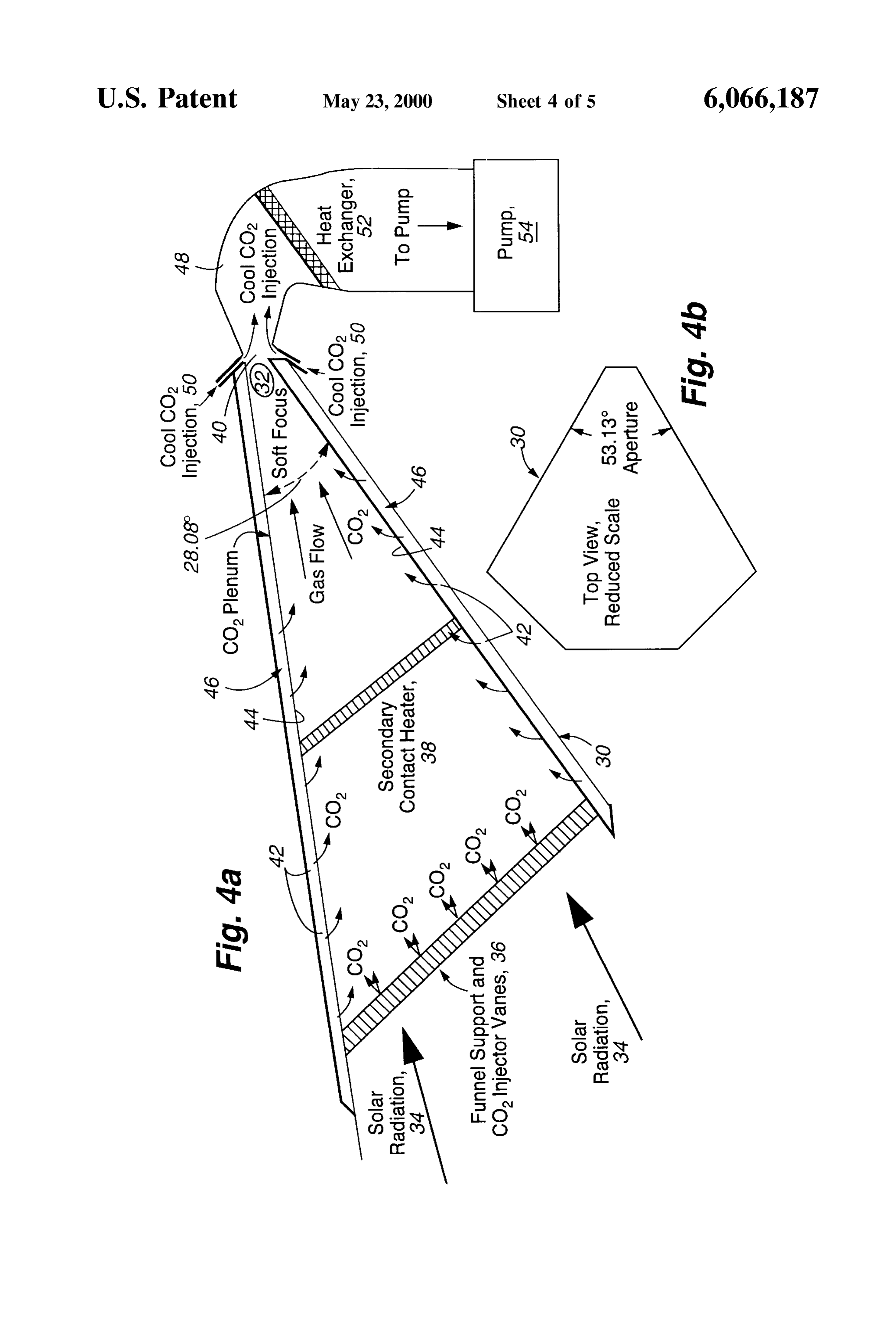
FIGS. 4a and 4b show the side view and the top view,
Tem- Wavelength (nm respectively, of a Solar funnel, 30, which concentrates Solar
power and hot CO into a reaction plenum where the CO2 60 will be exposed to a soft focus, 32, of Solar radiation. No 1523 2.9 + O.1 x 102 Solar window is required because the CO is introduced into
the funnel at high temperatures where it is much lighter than 2273 3.0 + O.1 x 102 8.4 + 0.4 x 10' air and will rise naturally into the funnel throat. Moreover, the CO introduction rate will be balanced against the 65 withdrawal rate from the funnel in order to prevent air from
Some Selected absorption croSS Sections from the Shock entering the funnel. The CO is first removed from ambient wave measurements of Generalov et al., Supra, are also air and heated before it is introduced into the funnel. It is
Page 10
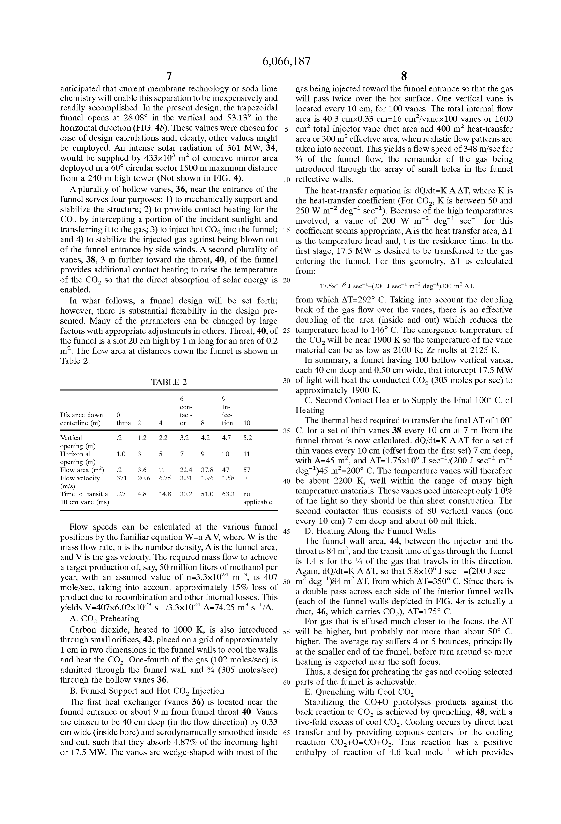
anticipated that current membrane technology or Soda lime gas being injected toward the funnel entrance So that the gas chemistry will enable this separation to be inexpensively and will pass twice over the hot Surface. One vertical vane is readily accomplished. In the present design, the trapezoidal located every 10 cm, for 100 vanes. The total internal flow funnel opens at 28.08 in the vertical and 53.13 in the area is 40.3 cmx0.33 cm=16 cm?/vanex 100 vanes or 1600 horizontal direction (FIG. 4b). These values were chosen for cm total injector vane duct area and 400 ml heat-transfer ease of design calculations and, clearly, other values might area or 300 m effective area, when realistic flow patterns are be employed. An intense solar radiation of 361 MW, 34, taken into account. This yields a flow speed of 348 m/sec for would be supplied by 433x10 m of concave mirror area % of the funnel flow, the remainder of the gas being deployed in a 60 circular sector 1500 m maximum distance introduced through the array of Small holes in the funnel from a 240 m high tower (Not shown in FIG. 4). reflective walls.
A plurality of hollow vanes, 36, near the entrance of the The heat-transfer equation is: dO/dt=KAAT, where K is funnel Serves four purposes: 1) to mechanically Support and the heat-transfer coefficient (For CO, K is between 50 and Stabilize the structure; 2) to provide contact heating for the 250 W m° deg' sec'). Because of the high temperatures CO by intercepting a portion of the incident Sunlight and involved, a value of 200 W m° deg sec' for this transferring it to the gas; 3) to inject hot CO into the funnel; 15 coefficient Seems appropriate, A is the heat transfer area, AT and 4) to Stabilize the injected gas against being blown out is the temperature head and, t is the residence time. In the of the funnel entrance by Side winds. A Second plurality of first stage, 17.5 MW is desired to be transferred to the gas vanes, 38, 3 m further toward the throat, 40, of the funnel entering the funnel. For this geometry, AT is calculated provides additional contact heating to raise the temperature from:
of the CO. So that the direct absorption of Solar energy is 17.5x1OJ sec'=(200J sec' m° deg")300 m? AT, enabled.
In what follows, a funnel design will be set forth; from which AT=292 C. Taking into account the doubling however, there is Substantial flexibility in the design pre back of the gas flow over the Vanes, there is an effective Sented. Many of the parameters can be changed by large doubling of the area (inside and out) which reduces the factors with appropriate adjustments in others. Throat, 40, of 25 temperature head to 146 C. The emergence temperature of the funnel is a slot 20 cm high by 1 m long for an area of 0.2 the CO will be near 1900 K so the temperature of the vane m. The flow area at distances down the funnel is shown in material can be as low as 2100 K. Zr melts at 2125 K. Table 2. In Summary, a funnel having 100 hollow vertical Vanes, each 40 cm deep and 0.50 cm wide, that intercept 17.5 MW
TABLE 2 of light will heat the conducted CO (305 moles persec) to approximately 1900 K.
C. Second Contact Heater to Supply the Final 100° C. of
Distance down O
jec
Heating centerline (m) throat 2 4 O 8 tion 10 The thermal head required to transfer the final AT of 100 35 C. for a set of thin vanes 38 every 10 cm at 7 m from the
Vertical .2 1.2 2.2 3.2 4.2 4.7 5.2 opening (m) funnel throat is now calculated. dO/dt=KAAT for a set of Horizontal 1.O 3 5 7 9 1O 11 thin vanes every 10 cm (offset from the first set) 7 cm deep, opening (m) with A=45 m, and AT=1.75x10 J sec/(200J sec' m? Flow area (m)
Flow velocity
deg')45 m=200° C. The temperature vanes will therefore
40 be about 2200 K, well within the range of many high
Time to transit a .27 4.8 14.8, 30.2 51.0 63.3 not temperature materials. These Vanes need intercept only 1.0% 10 cm vane (ms) applicable of the light so they should be thin sheet construction. The Second contactor thus consists of 80 vertical Vanes (one
Flow speeds can be calculated at the various funnel 45 every D.
10 cm) 7 cm deep and about 60 mill thick.
Heating Along the Funnel Walls positions by the familiar equation W=n AV, where W is the mass flow rate, n is the number density, A is the funnel area, throat is 84 m,wall
The funnel and area, 44, between the injector and the the transit time of gas through the funnel and V is the gas Velocity. The required mass flow to achieve is 1.4 S for the 4 of the gas that travels in this direction. a target production of, say, 50 million liters of methanol per year, with an assumed value of n=3.3x10' m, is 407 50 Again, dO/dt=KAAT, so that 5.8x10 J sec=(200J sec' m’ deg)84 mt AT, from which AT=350° C. Since there is mole/Sec, taking into account approximately 15% loss of a double pass acroSS each Side of the interior funnel walls product due to recombination and other internal losses. This (each of the funnel walls depicted in FIG. 4a is actually a yields V=407x6.02x10 s/3.3x10' A=74.25 m s/A. duct, 46, which carries CO), AT=175 C.
A. CO Preheating For gas that is effused much closer to the focus, the AT Carbon dioxide, heated to 1000 K, is also introduced 55 will be higher, but probably not more than about 50 C. through Small orifices, 42, placed on a grid of approximately higher. The average ray Suffers 4 or 5 bounces, principally 1 cm in two dimensions in the funnel walls to cool the walls at the Smaller end of the funnel, before turn around So more and heat the CO. One-fourth of the gas (102 moles/sec) is heating is expected near the Soft focus.
admitted through the funnel wall and % (305 moles/sec) Thus, a design for preheating the gas and cooling Selected through the hollow vanes 36. 60 parts of the funnel is achievable.
B. Funnel Support and Hot CO Injection E. Quenching with Cool CO
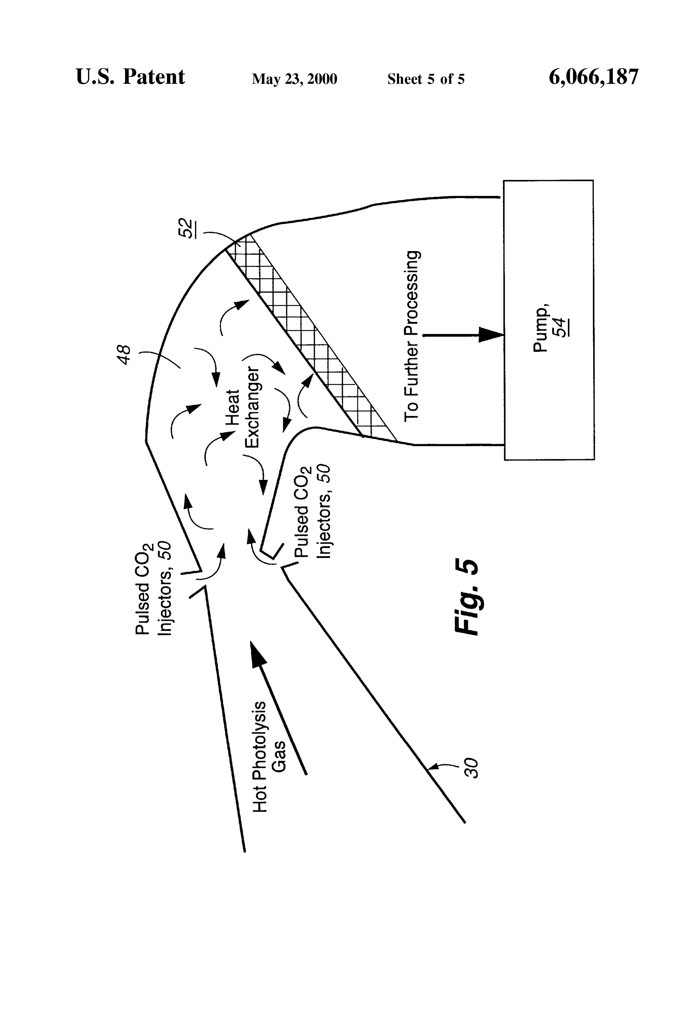
The first heat exchanger (vanes 36) is located near the Stabilizing the CO+O photolysis products against the funnel entrance or about 9 m from funnel throat 40. Vanes back reaction to CO is achieved by quenching, 48, with a are chosen to be 40 cm deep (in the flow direction) by 0.33 five-fold excess of cool CO. Cooling occurs by direct heat cm wide (inside bore) and aerodynamically Smoothed inside 65 transfer and by providing copious centers for the cooling and out, such that they absorb 4.87% of the incoming light reaction CO+O=CO+O. This reaction has a positive or 17.5 MW. The vanes are wedge-shaped with most of the enthalpy of reaction of 4.6 kcal mole' which provides
Page 11
cooling and additional CO. At temperatures over 2500 K the What is claimed is:
reaction is as fast or faster that the recombination reaction 1. A method for generating carbon monoxide from carbon CO+O=CO. The rapid mixing of cool CO assures that the dioxide, which comprises the Steps of:
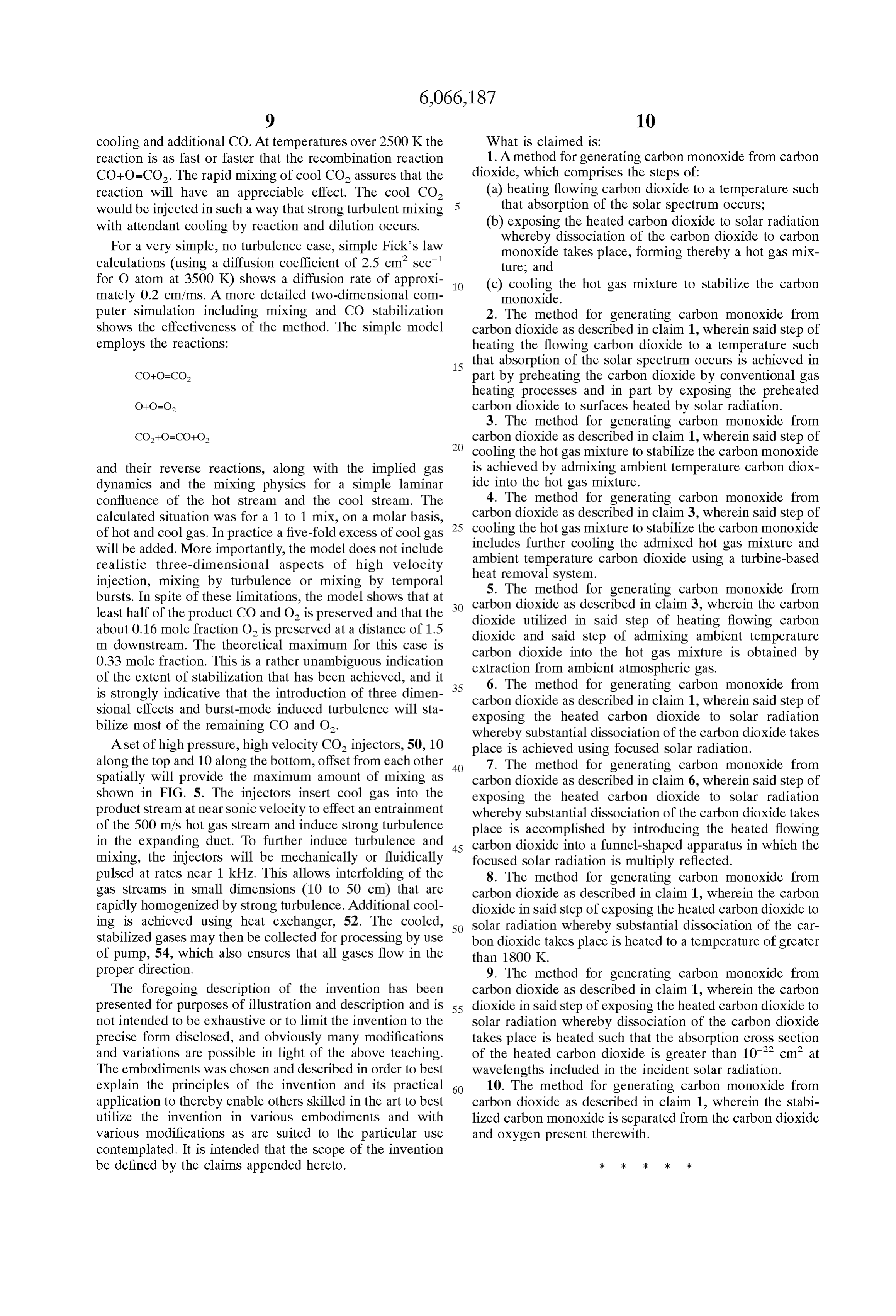
reaction will have an appreciable effect. The cool CO (a) heating flowing carbon dioxide to a temperature Such would be injected in Such a way that Strong turbulent mixing 5 that absorption of the Solar spectrum occurs, with attendant cooling by reaction and dilution occurs. (b) exposing the heated carbon dioxide to Solar radiation For a very Simple, no turbulence case, Simple Fick's law whereby dissociation of the carbon dioxide to carbon monoxide takes place, forming thereby a hot gas mix calculations (using a diffusion coefficient of 2.5 cm sec' ture; and for O atom at 3500 K) shows a diffusion rate of approxi (c) cooling the hot gas mixture to stabilize the carbon mately 0.2 cm/ms. A more detailed two-dimensional com monoxide.
puter Simulation including mixing and CO Stabilization 2. The method for generating carbon monoxide from shows the effectiveness of the method. The simple model carbon dioxide as described in claim 1, wherein Said Step of employs the reactions: heating the flowing carbon dioxide to a temperature Such 15 that absorption of the Solar Spectrum occurs is achieved in part by preheating the carbon dioxide by conventional gas heating processes and in part by exposing the preheated carbon dioxide to Surfaces heated by Solar radiation.
3. The method for generating carbon monoxide from carbon dioxide as described in claim 1, wherein Said Step of cooling the hot gas mixture to Stabilize the carbon monoxide and their reverse reactions, along with the implied gas is achieved by admixing ambient temperature carbon diox dynamics and the mixing physics for a simple laminar ide into the hot gas mixture.
confluence of the hot Stream and the cool Stream. The 4. The method for generating carbon monoxide from calculated Situation was for a 1 to 1 mix, on a molar basis, 25 carbon dioxide as described in claim 3, wherein Said Step of of hot and cool gas. In practice a five-fold excess of cool gas cooling the hot gas mixture to Stabilize the carbon monoxide will be added. More importantly, the model does not include includes further cooling the admixed hot gas mixture and ambient temperature carbon dioxide using a turbine-based realistic three-dimensional aspects of high Velocity heat removal System.
injection, mixing by turbulence or mixing by temporal 5. The method for generating carbon monoxide from bursts. In spite of these limitations, the model shows that at carbon least half of the product CO and O is preserved and that the dioxide dioxide as described in claim 3, wherein the carbon about 0.16 mole fraction O is preserved at a distance of 1.5 dioxide and SaidinStep utilized Said Step of heating flowing carbon of admixing ambient temperature m downstream. The theoretical maximum for this case is carbon dioxide into the 0.33 mole fraction. This is a rather unambiguous indication extraction from ambient atmospheric hot gas mixture is obtained by gas.
of the extent of stabilization that has been achieved, and it 35 6. The method for generating carbon monoxide from is strongly indicative that the introduction of three dimen carbon dioxide as described in claim 1, wherein Said Step of Sional effects and burst-mode induced turbulence will sta bilize most of the remaining CO and O. exposing the heated carbon dioxide to Solar radiation whereby Substantial dissociation of the carbon dioxide takes
A set of high pressure, high velocity CO injectors, 50, 10 place is achieved using focused Solar radiation. along the top and 10 along the bottom, offset from each other 40 7. The method for generating carbon monoxide from Spatially will provide the maximum amount of mixing as carbon dioxide as described in claim 6, wherein Said Step of shown in FIG. 5. The injectors insert cool gas into the exposing the heated carbon dioxide to Solar radiation product Stream at near Sonic Velocity to effect an entrainment whereby Substantial dissociation of the carbon dioxide takes of the 500 m/s hot gas Stream and induce Strong turbulence place is accomplished by introducing the heated flowing in the expanding duct. To further induce turbulence and 45 carbon dioxide into a funnel-shaped apparatus in which the mixing, the injectors will be mechanically or fluidically focused Solar radiation is multiply reflected. pulsed at rates near 1 kHz. This allows interfolding of the 8. The method for generating carbon monoxide from gas streams in Small dimensions (10 to 50 cm) that are carbon dioxide as described in claim 1, wherein the carbon rapidly homogenized by Strong turbulence. Additional cool dioxide in Said Step of exposing the heated carbon dioxide to ing is achieved using heat eXchanger, 52. The cooled, 50 Solar radiation whereby Substantial dissociation of the car Stabilized gases may then be collected for processing by use bon dioxide takes place is heated to a temperature of greater of pump, 54, which also ensures that all gases flow in the than 1800 K.
proper direction. 9. The method for generating carbon monoxide from The foregoing description of the invention has been carbon dioxide as described in claim 1, wherein the carbon presented for purposes of illustration and description and is 55 dioxide in Said Step of exposing the heated carbon dioxide to not intended to be exhaustive or to limit the invention to the Solar radiation whereby dissociation of the carbon dioxide precise form disclosed, and obviously many modifications takes place is heated Such that the absorption croSS Section and variations are possible in light of the above teaching. of the heated carbon dioxide is greater than 10° cm at The embodiments was chosen and described in order to best wavelengths included in the incident Solar radiation. explain the principles of the invention and its practical 60 10. The method for generating carbon monoxide from application to thereby enable others skilled in the art to best carbon dioxide as described in claim 1, wherein the stabi utilize the invention in various embodiments and with lized carbon monoxide is Separated from the carbon dioxide various modifications as are Suited to the particular use and oxygen present therewith.
contemplated. It is intended that the Scope of the invention be defined by the claims appended hereto. k k k k k
Provenance
- Collection
- Cited prior art
- Original PDF
- patentimages.storage.googleapis.com →
- Filed
- 1998-03-04
- Pages
- 11
- Method
- pdftotext (the PDF's own text layer) + pdftoppm 300dpi page scans
- Source
- Google Patents bibliographic record
- Granted
- 2000-05-23
- Inventors
- Reed J. Jensen; John L. Lyman; Joe D. King; Robert D. Guettler
- Transcribed from
- patentimages.storage.googleapis.com →