patent · US4330492
Carburetor
18 May 1982
Page 1 — bibliographic record
United States Patent (19) 11 4,330,492 Mohr (45) May 18, 1982 (54) CARBURETOR 4,106,457 8/1978 Totten et al. ....................... 123/546
76 Inventor: Russell R. Mohr, 103 Village Ave., 4,167,165 9/1979 Finlay et al......................... 123/546 Cannon Falls, Minn. 55009 4,194,476 3/1980 Lombardi et al. .................. 261/145 21 Appl. No.: 203,041 FOREIGN PATENT DOCUMENTS 22 Filed: Nov. 3, 1980 12321 4/1933 Australia .................... 261/DIG. 39 51) Int. Cl. ............................................. F02M 15/02 800923 12/1950 Fed. Rep. of Germany ... 123/554 52 U.S. Cl. ........................... 261/145; 261/DIG. 39; Primary Examiner-Tim R. Miles 261/71; 261/78 R; 48/180 A; 123/546 Attorney, Agent, or Firm-Norman P. Friederichs
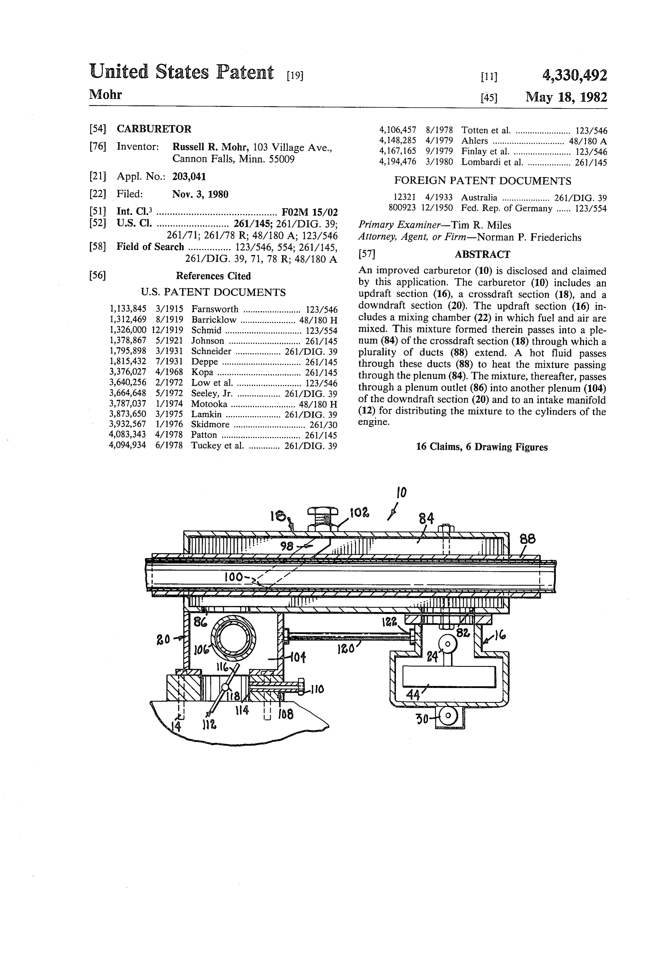
26i/DiG 35,717s R.48/180A (57) ABSTRACT o An improved carburetor (10) is disclosed and claimed 56) References Cited by this application. The carburetor (10) includes an
1,133,845 3/1915 Farnsworth ........................ 12.3/546 downdraft section (20). The updraft section (16) in 1,312,469 8/1919 Barricklow ....................... 48/180 H. cludes a mixing chamber (22) in which fuel and air are 1,326,000 12/1919 Schmid ..... ... 123/554 mixed. This mixture formed therein passes into a ple 1,378,867 5/1921 Johnson .............................. 261/145 num (84) of the crossdraft section (18) through which a 1,795,898 3/1931 Schneider .... ... 261/DIG. 39 plurality of ducts (88) extend. A hot fluid passes 1,815,432 7/1931 Deppe ................................. 261/145 through these ducts (88) to heat the mixture passing 3,376,027 4/1968 Kopa ............ or 261/15 through the plenum (84). The mixture, thereafter, passes 3,640,256 2/1972 5. et al. ........................... 123/546 through a plenum outlet (86) into another plenum (104)
3,787,037 1/1974 Motooka ........................... 48/180 H.
of the downdraft section (20) and to an intake manifold (12) for distributi h 3,873,650 3/1975 Lamkin .... 261/DIG. 39 ) for distributing the mixture to th lind the cylinders offth the 3,932,567 1/1976 Skidmore .............................. 261/30 engine.
4,083,343 4/1978 Patton ................................. 261/145 4,094,934 6/1978 Tuckey et al. ............. 261/DIG. 39 16 Claims, 6 Drawing Figures
IMITE" seat
Mik
BNS
Page 2
Drawing sheet — no readable text.
Page 3
Drawing sheet — no readable text.
Page 4
of the automobile engine. Typically, cars commercially
CARBURETOR available on the market do not include mechanisms for selectively varying the air/gasoline ratio of the mixture
TECHNICAL FIELD being introduced at the cylinders of the engine. The invention of the present application refers It is these problems extant in the art to which the broadly to the field of automotive mechanics. More invention of the present application is directed. It pro specifically, however, it is concerned with carburetors vides a structure which causes the air/gasoline mixture for use with internal combustion engines. In a preferred to be heated virtually up until the point at which the embodiment, the invention relates to an improved car mixture enters the engine cylinders. Additionally, it buretor including means for heating the air/fuel mixture effectuates more complete atomization of the gasoline after those two components are combined and vapor prior to it being combined with air so that more com ized. plete vaporization will occur. It also provides means for
BACKGROUND OF PRIOR ART
selectively regulating the volumes of both air and gaso line which combine to form the mixture introduced into
Because of a number of factors, not the least impor 5 the cylinders.
tant of which is the rising cost of gasoline, the develop BRIEF SUMMARY OF THE INVENTION ment of fuel efficient automobiles has become an urgent project of the world's technological community. Nor is The present invention is an apparatus for qualita there any indication that fuel costs will decline in the tively conditioning the air/fuel mixture which enters foreseeable future so as to reduce the importance of the 20 the cylinders of an internal combustion engine. The development of more fuel efficient cars. apparatus includes a mixing chamber in which combin A number of factors bear upon the efficiency of the ing of the air and fuel occurs. Inlet means are provided typical internal combustion engine used in the majority to supply both fuel and air to the chamber. The cham of automobiles produced in the United States and other ber is in communication with a plenum through an countries. One of these factors is the degree to which 25 entrance to the plenum. The air/fuel mixture, therefore, the air/gasoline mixture introduced into the cylinders can pass from the chamber into the plenum and through of the engine is vaporized. Many carburetors, which the plenum to an outlet. Structure is provided for heat effect this function, currently in use on automobiles ing the air/fuel mixture while it passes through the today do not effectuate sufficient vaporization in order plenum. After leaving the plenum through the outlet, to maximize the engine efficiency. 30
Degree of vaporization is basically the function of the mixture is conveyed to the cylinders where it is combusted.
two factors: (1) the amount of dispersal and atomization In one embodiment of the invention, a plurality of of fuel droplets at the time the fuel is combined with air; ducts and (2) the temperature of the mixture as it is introduced taken can extend through the plenum, and exhaust gas into the cylinders of the engine for combustion. With through thesethe 35 from engine exhaust pipe can be passed ducts. The heat from the exhaust gas will, respect to the first of these factors, the typical carbure thereby, be transferred to the air/fuel mixture after it is tor relies upon a reduced pressure created within an combined.
induction pipe by an increased velocity of air flow to atomize gasoline being sucked out of a choke tube. Passage of the combustable mixture through the ple Frequently, this process is not adequate to accomplish a 40 num can be facilitated by providing an air jet within the desired degree of atomization. plenum, the jet having a nozzle disposed proximate, and With respect to the second factor, heating of air intro directed toward, the plenum's outlet. Such a structure duced into the induction pipe prior to its entry therein is creates a reduced air pressure and suction to cause the relied upon to raise the temperature of the air/fuel mix mixture to flow through the plenum. ture to the necessary level. An inadequately heated 45 The air ejected by the jet can be heated prior to its mixture often results since the temperature of the gaso exiting the nozzle, but, in some cases, it may still have a line is lower than that of the air as it enters the induction lower temperature than that of the mixture exiting the pipe. Consequently, a transfer of heat energy from the plenum. In order to reheat the mixture, it can be passed air to the gasoline occurs at time of mixing, and the through a second plenum having a conduit extending heated air temperature becomes lowered. Additionally, 50 therethrough. As with the ducts in the first plenum, heat is expended during the vaporization process. A exhaust gas from the engine exhaust pipe can be passed final cause of heat loss is the transfer of thermal energy through this conduit to provide a source of thermal from the air between the time it absorbs heat from the energy.
engine exhaust until the time it enters the induction In one embodiment, the invention includes structure pipe. 55 for leaning the gasoline/air ratio in the mixture entering Another factor which reduces the efficiency of the the cylinders. This can be accomplished by use of appa automobile engine while it is operating is the inability to ratus for selectively regulating the volume of gasoline, selectively regulate the relative amounts of air and gaso relative to that of air, which is introduced into the mix line which make up the mixture going into the cylinders ing chamber. In applications of the invention wherein it in response to the conditions under which the car is 60 is used on an automobile, means can be provided for being operated. During acceleration periods, a greater selectively regulating this volume remotely from the percentage of gasoline with respect to the percentage of occupant compartment of the automobile. air in the mixture is necessary than at higher highway A perferred embodiment of the invention includes a cruising speeds. At these higher speeds and under con fuel dispersal and atomizing device within the mixing ditions in which there is not frequent acceleration and 65 chamber for facilitating maximum vaporization of the deceleration, however, the percentage of gasoline with gasoline as it is mixed with air. The device can include respect to the percentage of air can be significantly a circularly cylindrical, tubular fuel dispersal element reduced without any appreciable reduction in efficiency which projects into the mixing chamber from a fuel
Page 5
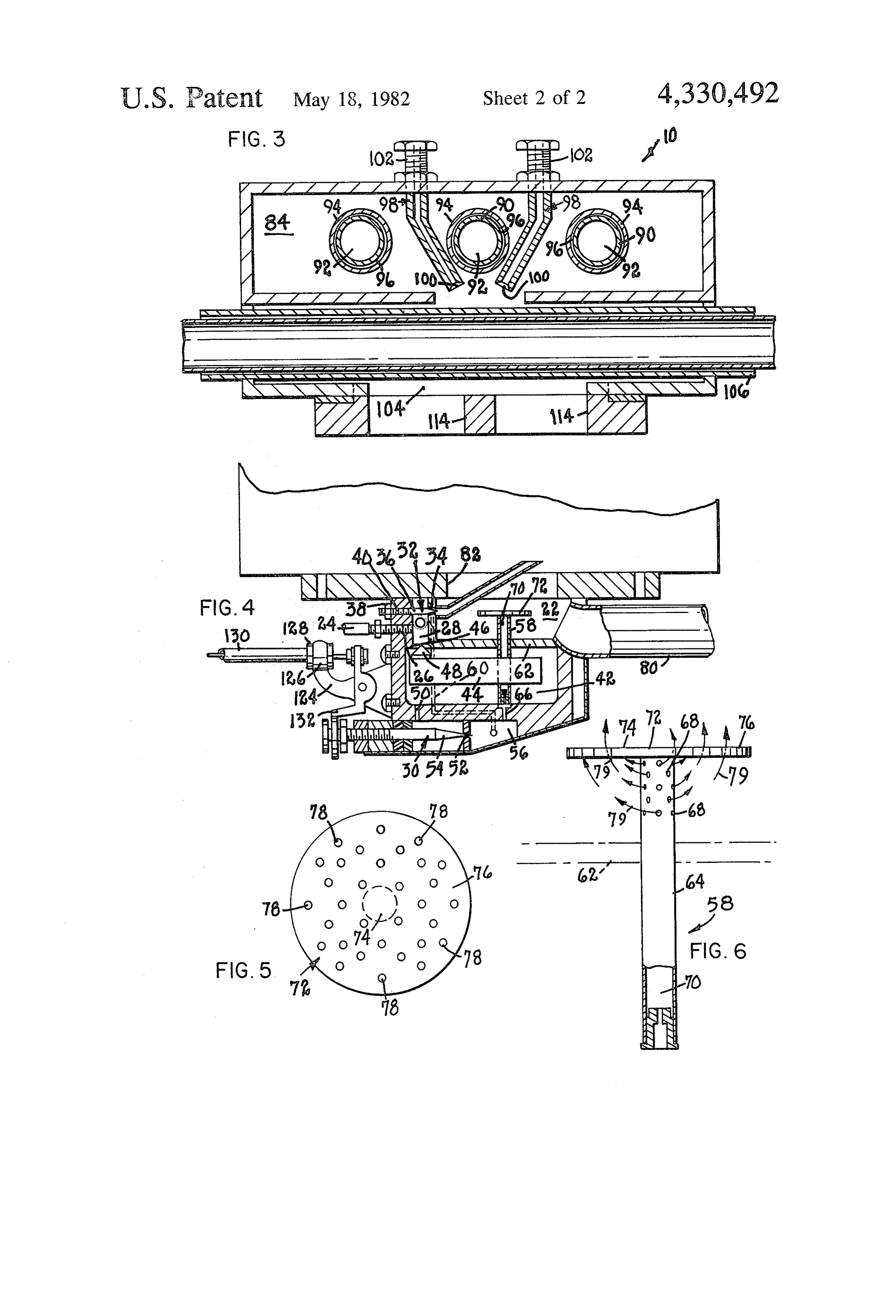
inlet port. A bore, extending the length of the element, section 16. Fuel enters first into a first chamber 28 communicates, at an end by which the element is cap which provides fuel for both the main jet 30 and the tured, with the fuel inlet port. The free end of the ele idling jet 32. Fuel is continuously fed from chamber 28 ment is occluded by an imperforate portion of a disc to the idling jet 32 which comprises a needle valve like closure member. A multiplicity of perforations are having an orifice 34 and a needle element 36 which can provided in the lateral wall of the dispersal element, be selectively moved axially with respect to the orifice through which perforations fuel in the bore passes radi 34 to manually adjust the fuel rate of flow therethrough. ally outward and is partially atomized. Typically, this setting is made and maintained during The disc-like closure member can include a periph normal operation of the engine. Adjustments are made eral portion which extends radially beyond the lateral O only when it is felt that the idle of the engine is either wall of a dispersal element. That peripheral portion of too fast or too slow. Adjustments can be made by loos the disc-like element can also include perforations dis ening or tightening a lock nut 38 positioned on a shaft 40 posed in the flow path of the vaporizing gasoline, and a extending from the needle element 36. second stage of atomization can occur as the gasoline A reservoir 42 is provided to hold a ready supply of passes through these perforations. 15 fuel to the main jet assembly 30. A float 44 is disposed The invention of this application is thus a carburetor within the reservoir 40 and positioned so that, as the which provides improved efficiency of operation of the float 44 rises, a port 46 from the fuel entry chamber 28 engine with which it is used. Specific advantages of the can be closed by a needle valve element 48 positioned invention will become apparent with reference to the on the float 44. Closure of the port 46 occurs as the accompanying drawings, detailed description of the 20 reservoir 42 fills and the float 44 rises. As fuel from the invention, and claims. reservoir 42 passes through a passage 50 to the main jet BRIEF DESCRIPTION OF THE DRAWINGS orifice 52, the fuel in the reservoir 42 will drop, the float 44 will lower, and additional fuel will pass into the
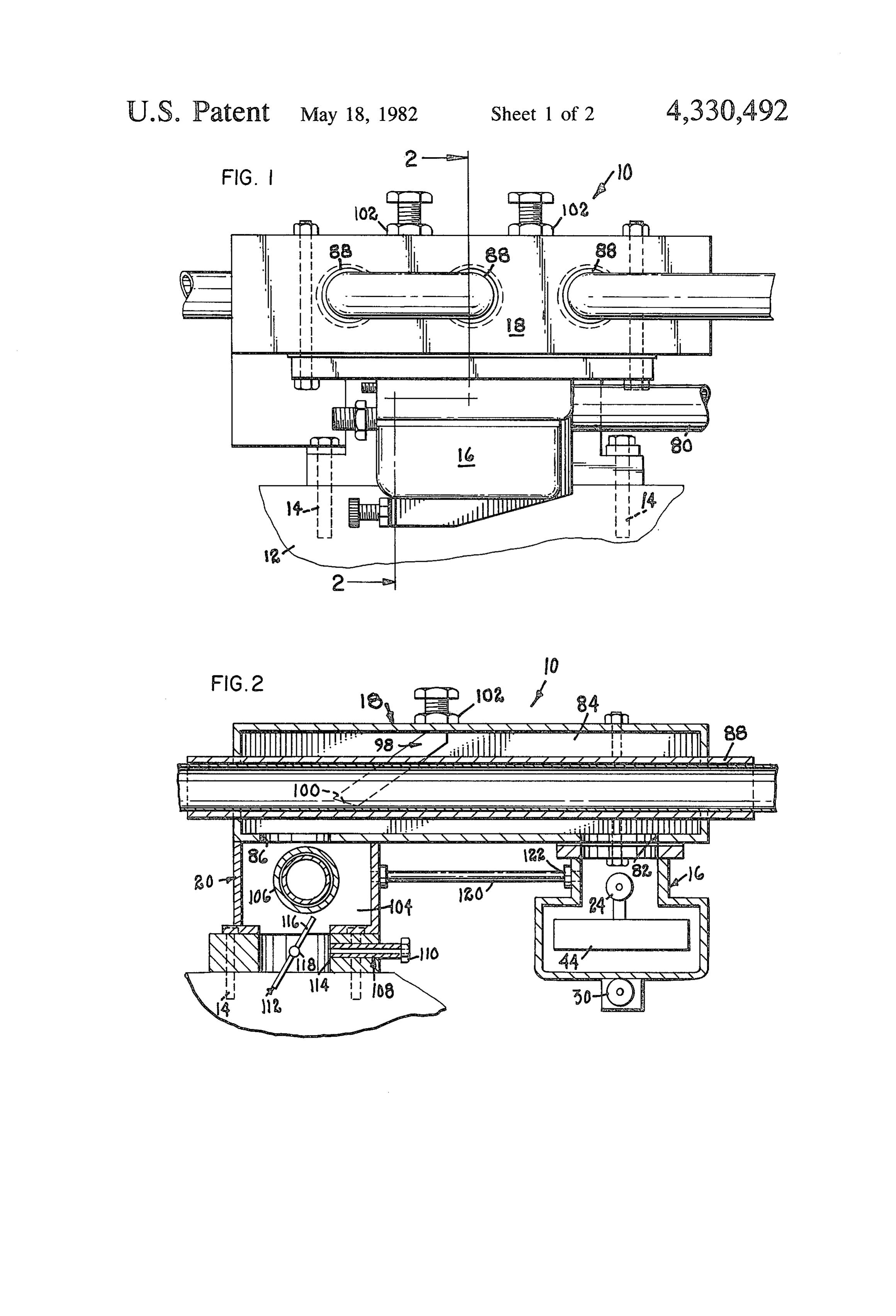
FIG. 1 is a side elevational view of an embodiment in reservoir 42 until the float 44 again rises to close the accordance with the present invention; 25 port 46.
FIG. 2 is a view taken along line 2-2 of FIG. 1; The main jet 30 can be set in a fixed position so that FIG. 3 is a side elevational view in cross section a needle portion 54 thereof can be positioned relative to showing air jets, a second plenum, and a conduit by the main jet orifice 52 with a desired rate of fuel flowing which the second plenum is heated; through the orifice 52 per unit time. FIG. 4 is a side elevational view in cross section 30 Fuel passes through the main jet orifice 52 into a showing the mixing chamber and means for leaning the second chamber 56 which feeds a fuel dispersal and air/fuel ratio; atomizing device 58 and a line augmenting flow FIG. 5 is a plan view of the fuel dispersal and atomiz through the idling jet 32. The dispersal and atomizing ing device of FIG. 6 and; device 58 extends up through the main jet reservoir 42 FIG. 6 is an elevational view of a fuel dispersal and 35 and can serve as means for aligning the float 44 for atomizing device in accordance with one embodiment vertical movement. The device 58 further extends of the present invention, some portions thereof being through a generally horizontal plate 62 defining the broken away. upper wall of the reservoir 42 and into the mixing cham
DETAILED DESCRIPTION OF THE
INVENTION The device 58 includes a fuel dispersal element 64 which can be a circularly cylindrical, tubular member
Referring now to the drawings wherein like refer which projects from the inlet port 66 into the mixing ence numerals denote like elements throughout the chamber 22. At its first end, the element's lateral wall several views, FIGS. 1 and 2 illustrate a carburetor encircles the port 66 providing access to the mixing made in accordance with a preferred embodiment of the 45 chamber 22, and a second end of the element 64 which present invention. The carburetor, generally illustrated extends into the chamber 22 has a multiplicity of perfo by the reference numeral 10, is shown, particularly in rations 68 formed through the lateral wall. FIG. 2, as attached to an upper portion of an intake The second end of the bore 70 formed in the tube 64 manifold 12 of the type typically on internal combustion is closed by a closure member. This member can com engines which drive automobiles, trucks, and other 50 prise a generally circular disk 72 mounted to the tubular vehicles. It will be understood that the carburetor 10 element 64 at its second end. In one embodiment, the illustrated can appropriately be used both on 8 cylinder disk 72 can be disposed to define a plane generally per engines as used in large automobiles, trucks, and larger pendicular to the axis along which the tubular member vehicles, and on 4 and 6 cylinder engines as used in 64 projects.
small automobiles. The carburetor 10 can be attached to 55 An interior portion 74 of the disk 72 is made imper the intake manifold 12 by appropriate means such as forate to occlude the second end of the cylindrical ele bolts 14. ment 64. Fuel which passes up the cylindrical member The carburetor 10 includes an updraft section 16, a 64 by means hereinafter defined is thus forced to pass cross draft section 18, and a downdraft section 20. It through the perforations 68 through the lateral wall of thus can efficiently utilize, and be positioned in a com the member 64 and into the mixing chamber 22. By paratively small, space. passing through these perforations 68, the fuel is dis Referring now to FIG. 4, the updraft section 16 in persed in all directions and finally atomized. cludes a mixing chamber 22 in which air and fuel are The peripheral portion 76 of the disk 72 which ex mixed. A fuel line 24 is provided to channel fuel from a tends laterally beyond the wall of the dispersal element tank or fuel heater (not shown) to a fuel inlet at the 65 64 can also be perforated so that fuel droplets, as they updraft assembly. The fuel line 24 can be coupled to the rise, are passed through a second dispersal and atomiza updraft assembly 16 by threading it into a female tion stage. Some fuel droplets may evade this second threaded orifice 26 formed in the wall of the updraft stage conditioning and pass outside the disk 72, but a
Page 6
large percentage of the droplets will, in fact, be passed and qualitatively at this stage. Qualitatively, additional through these perforations 78. Flow will generally be in heat can be added to the mixture by the provision of a a path illustrated by arrows 79. .. conduit 106 extending through this second plenum 104, Fuel line 60 extends from chamber 56 to the idling through which conduit exhaust gas is passed. The con orifice 34. When the main jet 30 is open, therefore, fuel duit 106 can be similar in cross sectional construction to flow through the idling jet 32 will be augmented by fuel that of the ducts 88 in the first plenum 84. Exhaust gases passing through line 60. If main jet 30 is closed, fuel can enter this conduit 106 through an entry in one end flow to idling jet 32 through line 60 will be precluded. thereof, pass through the conduit 106, and, thereafter, An air intake 80 provides a source of heated air into be vented.
the mixing chamber 22. The thermal energy which the 10 Quantitatively, an additional air source 108 can be air has can be obtained by passing it near a hot exhaust provided at this stage to reduce the relative proportion pipe (not shown). of fuel in the air/fuel mixture. A flow control valve 110 As the heated air enters the mixing chamber 22, heat is provided for this purpose. As with air introduced into will be transferred to the already partially vaporized the mixture through the air jets 98 disposed in the first fuel droplets. As a result, a high degree of vaporization 15 plenum 84, air introduced at this stage would also be will occur. The air/fuel vapor will, thereafter, pass preheated. As can be seen, therefore, the addition of through a plenum entrance 82 into the cross draft sec heated air to the mixture at the various sections of the tion 18 of the carburetor 10, carburetor 10 provide additional heat to maximize the The cross draft section 18 includes a plenum 84 ex vaporization of the air/fuel mixture which eventually tending between the updraft and the downdraft sections 20 makes its way to the intake manifold 12. 16, 20. The air/fuel mixture passes through the plenum A conventional butterfly valve 112 is mounted in a 84 and exits, at the opposite end thereof through the restriction 114 providing communication between the plenum outlet 86 into the downdraft section 20 of the second plenum 104 and the intake manifold 12. A disc carburetor 10. shaped valve element 116 is caused to pivot about a As the mixture passes through the plenum 84, it is free 25 shaft 118 and to open the restriction 114 in response to to circulate around a plurality of ducts 88 extending pressure brought to bear upon the acceleration peddle through the plenum 84. The ducts 88 can have a sub mounted in the occupant compartment of the vehicle in stantially cylindrical inner wall 90 which defines an which the carburetor 10 is mounted. No further discus inner passage 92. Hot exhaust gases from the exhaust sion of this particular structure will be made since its manifold or exhaust pipe can be made to pass through 30 function and operation is well known in the art. this inner passage 92. A substantially cylindrical outer When starting a vehicle on a particularly cold morn wall 94, and in certain embodiments coaxial with the ing, the air/fuel mixture going to the cylinders must be inner wall 90, is radially spaced outwardly from the extremely rich. The invention of this application pro inner wall 90 to define an annular chamber 96 between vides means for by-passing the first plenum 84 and the two walls 90,94. Provision of these ducts 88 effectu 35 pumping fuel directly from the updraft section 16 of the ates a high degree of thermal energy transfer from the carburetor 10 to the downdraft section 20. A tubular exhaust gases passing within the inner wall 90 to the bridge 120 is provided for this purpose. Valve means air/fuel mixture circulating about the outer wall 94. (not shown) can be included to selectively actuate flow Means can be provided to induce flow of the mixture of fuel through the tubular bridge 120. At its end 122 at through the plenum 84. One or a series of air jets 98 can 40 which it communicates with the updraft section 16, the be positioned so that the nozzles 100 of the jets 98 are bridge 120 is attached to the wall thereof so that fuel proximate, and directed toward, the plenum outlet 86. supplied by the fuel line 24 to the first chamber 28 can The reduced pressure which thereby results at the out be permitted to pass through the tubular bridge 120. let end of the plenum 84 will cause the mixture to pass Once the fuel reaches the second plenum 104, it is fed through the plenum 84 and about the ducts 88. Addi 45 into the intake manifold 12 by manipulation of the accel tionally, this creation of a vacuum at the outlet end of eration peddle to open the butterfly throttle valve 112. the plenum 84 will also effectuate the passing of fuel When the vehicle is accelerated to higher speeds and upwardly through the fuel dispersal and atomizing ele the speed is maintained relatively constant, the richness ment 58. of the mixture can be decreased by use of leaning means Flow control valve means 102 can be provided to 50 for selectively regulating the volumetric flow of fuel control the volume of air ejected by the nozzles 100 of through the main jet orifice 52 per unit time. As previ the air jets 98 and to heat the air prior to its being intro ously discussed, when the engine is not running the duced into the first plenum 84. Since it is an objective of main jet valve needle can be adjusted so that the fuel the invention of this application to maintain the temper flow rate is optimal considering all of the conditions ature of the air/fuel mixture at a high level by the provi 55 under which the vehicle is operated. The leaning means, sion of heating means in the plenum 84, the objective however, provides the operator of the vehicle with the would be somewhat frustrated by inserting cold air at ability to regulate the flow of fuel during operation. this point. As with the intake air injected into the mixing A strut 124 can be made to extend from the wall of chamber 22, therefore, this air can be passed proximate the updraft section 16 of the carburetor 10. A clamp either the exhaust manifold or exhaust pipe prior to 60 portion 126 at the end of the strut 124 can secure a being injected into the plenum 84 so that it will contain sleeve 128 supporting a bowden cable 130. One end of a significant amount of thermal energy. the cable 130 is mounted within the occupant compart The air/fuel mixture thus augmented by additional ment of the vehicle so that the vehicle's operator can hot air from the air jets 98 passes through the plenum manipulate the cable. The other end is attached to one outlet 86 into the downdraft section 20 of the carburetor 65 end of a lever 132 pivotally mounted to the strut 124. 10. The downdraft section 20 comprises a second ple The other end of the lever 132 is attached to the adjust num 104 immediately adjacent the first plenum 84. The ing end of the needle control valve element 54. Pulling air/fuel mixture can be conditioned both quantitatively of the cable 130 by the vehicle's operator will cause a
Page 7
counterclockwise rotation of the lever 132 and a conse (b) means for selectively controlling the fuel flow rate quential axial movement of the needle valve element 54 through said orifice.
into the orifice 52. This will reduce the fuel flow 7. In combination with an automobile including an through the main jet orifice 52 and idling orifice 34 and occupant compartment; apparatus in accordance with lean the air/fuel mixture transiting to the intake mani 5 claim 6 wherein said selective control means comprises: fold. (a) a needle valve having a needle member moveable Numerous characteristics and advantages of the in axially into and out of a fuel port; and vention have been set forth in the foregoing description (b) remote means disposed in the occupant compart of a preferred embodiment. This description is, of ment of the automobile to control axial movement course, only illustrative in many respects. Changes may O of said needle member.
be made in details, particularly in matters of shape, size, 8. Apparatus in accordance with claim 1, further and arrangement of parts without exceeding the scope including:
of the invention. It will be understood that the scope of (a) a fuel dispersal element having first and second the invention is defined in the language of the appended ends and a bore extending between said ends, de claims. 15 fined therein by a lateral wall, said lateral wall What is claimed is: encircling said fuel inlet means at said first end of 1. Apparatus for conditioning an air/fuel mixture for said element and having a multiplicity of perfora introduction into the cylinders of an internal combus tions formed therethrough; and tion engine, comprising: (b) a dispersal element closure member closing said (a) fuel inlet means; 20 second end of said element and having a portion (b) air inlet means; extending peripherally beyond said lateral wall, (c) a mixing chamber into which said fuel and air inlet said peripherally extending portion also having a means converge and wherein fuel and air are multiplicity of perforations formed therethrough. mixed; 9. The combination of claim 8 wherein said lateral (d) means for selectively adjusting the ratio of fuel to 25 wall is generally circularly cylindrical and elongated in air in said mixture; an axial direction.
(e) a plenum positioned above said mixing chamber 10. The combination of claim 9 wherein said closure and having an entrance at said mixing chamber member is a circular disk coaxial with said lateral wall. providing communication between said plenum 11. Apparatus in accordance with claim 1, further and said mixing chamber and an outlet providing including:
communication between said plenum and said cyl (a) a cylindrical, tubular element projecting along an inders, said plenum including at least one duct axis from a carburetor fuel inlet means and having extending through said plenum, said duct having an a captured end proximate said fuel inlet means and outer wall and an inner wall defining an annular a free end opposite the port, said element having a chamber surrounding an inner passage through 35 bore, coaxial therewith, extending axially there which hot exhaust gases can be made to pass, said through, and a plurality of perforations affording annular chamber effectuating heat transfer from communication between said bore and an external said hot exhaust gases traveling through said pas surface of said element; and sage to said mixture, whereby said mixture is fur (b) a circular disk mounted to said element at said free ther vaporized; and 40 end thereof, said disk having an imperforate inte (f) means for conveying said mixture from said outlet rior hub portion closing said free end of said tubu of said plenum to said cylinders, said means includ lar element, and a perforated peripheral portion. ing a valve mounted in a restriction of said outlet 12. The device of claim 11 wherein said disk defines for varying the rate of mixture transfer from said a plane generally perpendicular to said axis of projec plenum to said cylinders, said plenum trapping and 45 tion.
retaining said mixture until said valve opens said 13. A carburetor comprising:
restriction and enables conveyance of said mixture (a) an updraft section which includes: to the cylinders; whereby said mixture is retained (i) fuel inlet means;
in said plenum and continuously heated and further (ii) air inlet means;
vaporized until needed at said cylinders. 50 (iii) fuel dispersal and atomizing means; 2. Apparatus in accordance with claim 1 further com (iv) means for mixing hot air with atomized fuel prising means for inducing flow of said mixture through droplets; and said plenum and to the cylinders. (v) means for regulating the relative ratio of atom 3. Apparatus in accordance with claim 2 wherein said ized fuel droplets to hot air; inducing means comprises at least one air jet disposed 55 (b) a crossdraft section located above said updraft within said plenum and having a nozzle proximate, and section into which said mixture is introduced from directed toward, said outlet. said updraft section and which includes: 4. Apparatus in accordance with claim 3 further com (i) a first plenum;
prising means for heating air ejected by said at least one (ii) a first plenum outlet; jet prior to its ejection from said nozzle. 60 (iii) means for ejecting mixture flow through said 5. Apparatus in accordance with claim 4 further com first plenum to said outlet; and prising means for controlling the volumetric rate of (iv) a plurality of ducts extending through said first flow of heated air ejected by said at least one jet. plenum and having a heated exhaust passing 6. Apparatus in accordance with claim 1 wherein said therethrough, said ducts having a substantially mixing chamber includes a wall defining said chamber 65 cylindrical inner wall defining an inner passage and wherein said fuel inlet means comprises: through which exhaust passes, and a substan (a) an orifice through said wall and entering into said tially cylindrical outer wall radially spaced from chamber; and said inner wall and defining a closed annular
Page 8
9 O space between said outer and inner wall, said being heated, the ratio of fuel to air in said mixture annular space effectuating the controlled trans- can be increased, thereby facilitating cold starts. fer of heat from said heated exhaust to said mix- 14. The carburetor of claim 13 wherein said further ture; heating means comprises an elongated conduit extend (c) a downdraft section located below said crossdraft 5 ing through said second plenum and wherein said con section into which said mixture is introduced from duit and said ducts have entry ends which communicate said crossdraft section and which includes: with the exhaust pipe from the engine and through (i) a second plenum; which exhaust from the engine enters said conduit and (ii) a transfer means from said second plenum to said ducts.
cylinders of an engine to which the carburetor is 10 15. The carburetor of claim 13 wherein said fuel dis attached, said transfer means including a valve persal and atomizing means comprises:
for varying the rate of mixture transfer from said (a) a vertically disposed tube having a first end into Second plenum to said cylinders, whereby said which fuel flows, a second end, and a side wall mixture is trapped in said crossdraft section until enclosing a bore extending between said ends, said transferred to said cylinders; 15 side wall having a multiplicity of perforations (iii) means located in said downdraft section for formed therethrough; and further heating said mixture; and (b) a platen having an interior portion occluding said (iv) means located in said downdraft section for bore at said second end of said tube and a periph selectively adjusting ratio of fuel to air; eral portion, said peripheral portion having a multi (d) means for selectively bypassing said crossdraft 20 plicity of perforations formed therethrough. section and transferring said mixture directly from 16. The carburetor of claim 13 wherein said valve said updraft section to said downdraft section, comprises a butterfly throttle valve. whereby during cold starts, prior to engine exhaust k
Provenance
- Collection
- Cited prior art
- Original PDF
- patentimages.storage.googleapis.com →
- Filed
- 1980-11-03
- Pages
- 8
- Method
- pdftotext (the PDF's own text layer) + pdftoppm 300dpi page scans
- Source
- Google Patents bibliographic record
- Granted
- 1982-05-18
- Inventors
- Russell R. Mohr
- Transcribed from
- patentimages.storage.googleapis.com →