patent · US1777472
Carburetion apparatus
7 October 1930
Page 1
Drawing sheet — no readable text.
Page 2
Drawing sheet — no readable text.
Page 3
Drawing sheet — no readable text.
Page 4
Patented Oct. 7, 1930 1,777,472
FRANK C. MOCKAND JOHN A. DIENNER, OF CHICAGO, ILLINOIs, ASSIGNORS TO BENDIX. STROMBERG CARBURETOR COMPANY, OF SOUTH BEND, INDIANA, A CORPORATION
OE ITNOS
CARBURETION APPARATUs
Application filed July 5, 1921. Serial No. 482,318.
The present invention relates to carbure particles of the accelerating charge because tion apparatus, and has particular reference of the delay in the vaporization and the lack to a method of and means for vaporizing the of quick responsiveness. To overcome this liquid fuel, or rendering the same easier to difficulty the present invention has as its pri S. vaporize by the application of heat thereto. mary object to provide means which will heat 55 This is for the purpose of increasing the com or vaporize the accelerating charge of fuel bustibility and power of the mixture and its separately from the main air stream or from responsiveness to acceleration. the unvaporized particles of the main charge It has heretofore been proposed to vaporize of fuel. The advantages of this practice are 10 the liquid fuel particles in the mixture by di numerous: First, it avoids undue heating of 60 recting the entire volume of mixture against the air component of the mixture with the a hot spot in the intake manifold, or by sep consequent disadvantages pointed out above; arating the unvaporized particles of fuel out second, it accommodates any preferred man of the mixture stream and retaining them in ner of treating the main body of fuel in the : 5, continued subjection to heat until vaporized. mixture independently of the accelerating 65 The first of these methods has the undesirable charge and permits of any desired time delay effect of heating the air undesirably and in the vaporization of the “heavy ends' of thereby reducing the volumetric efficiency of the main charge of fuel; third, it insures in the engine and causing excessive heating of stantaneous response of fuel for acceleration. 20 the engine and impairment of its lubricating This accelerating charge is preferably va G function. The second method is deficient in porized by contact with a “hotspot' or vapor that it is necessary to provide for delaying the izing surface which is individual to that par passage of the unvaporized particles of fuel ticular function. This vaporizing surface is
to the cylinder in order to supply sufficient designed to maintain an intense heat and ow heat for their vaporization, and thus the flow ing to the fact that a full accelerating charge 5 of fuel to the engine is not sufficiently respon only contacts with the vaporizing surface sive for quick acceleration. There are numer intermittently a large reserve accumulation ous factors which cause this delay in the pas of heat can be stored in this surface for in sage of the unvaporized fuel to the engine. stantaneous vaporization of the accelerating 30 The heavy ends of the fuel frequently have charge. 80 boiling temperatures approximately 450 F. Referring to the accompanying drawings or more. The proportion of unvaporized fuel wherein we have illustrated a preferred em in the average mixture requires a fairly large bodiment of our invention:
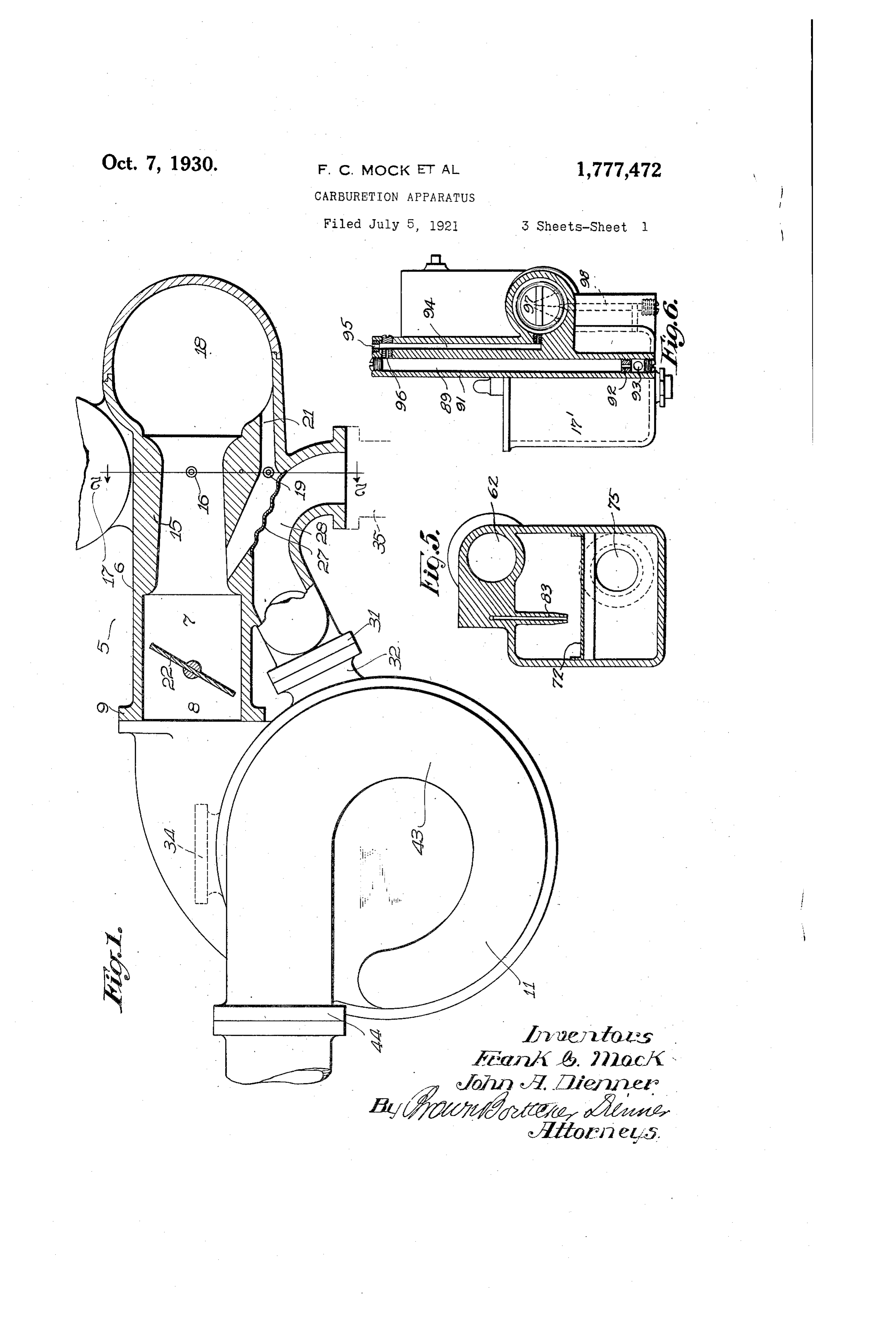
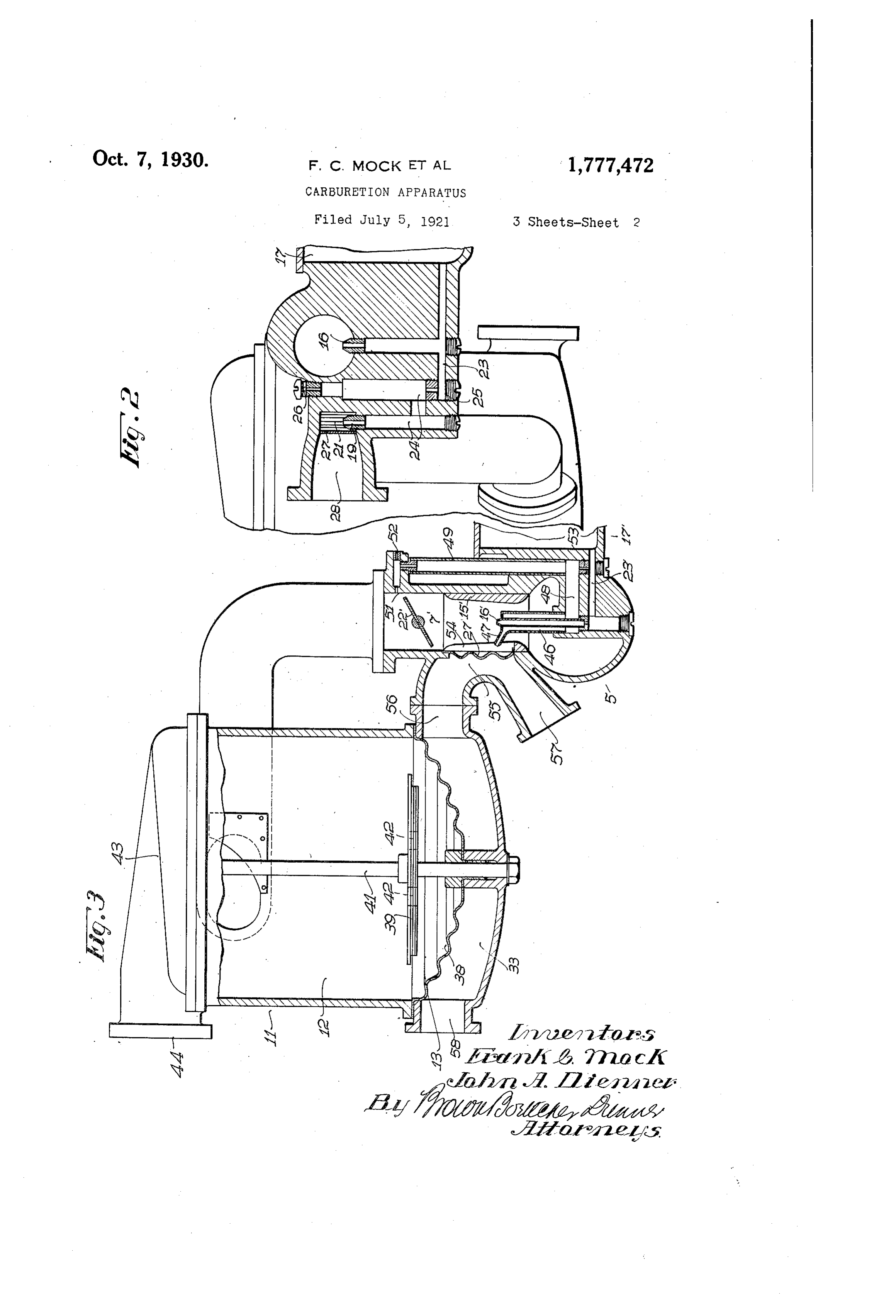
vaporizing area, while the exhaust tempera Figure 1 is a plan view of our improved 35 tures which may be employed to heat this va carburetion apparatus, showing the main 85 porizing area are limited. Moreover, the fuel separating chamber in elevation and the time interval of one cycle of the mixture is carbureter in horizontal section; very short, the average interval embracing Figure2is a transverse sectional view taken the vaporization, compression and expansion approximately on the line 2-2 of Figure 1; 4. of one charge at intermediate engine speeds Figure 3 is a vertical sectional view of an 90 being approximately 1/25th second. In view other form of our invention;
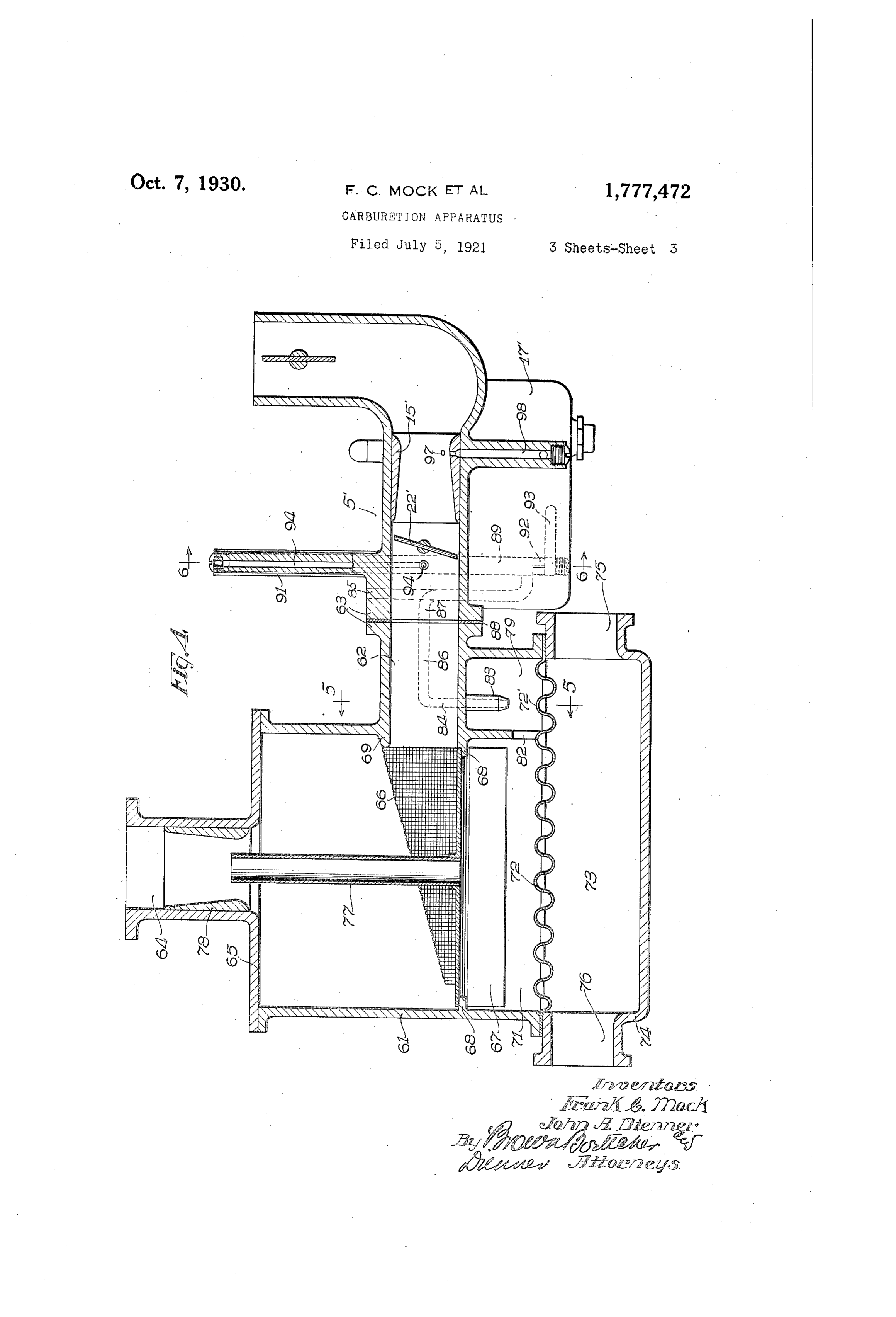
of these conditions it has been found to be de Figure 4 is a complete sectional view of an sirable, if not necessary, to delay the passage other form of our invention; of these unvaporized particles of fuel by sep Figure 5 is a detail section taken on the 45 arating them out of the mixture stream and line 5-5 of Figure 4; and 95 retaining them in subjection to the vaporizing Figure 6 is a similar view taken on the means until completely vaporized. line 6-6 of Figure 4.
But, as before stated, during acceleration The carbureter, which is designated 5 in this method of vaporizing the fuel particlesis its entirety, comprises a casing 6 forming a 50 not adequate for the vaporization of the fuel carbureting chamber 7 and a mixture outlet 8. 00
Page 5
The mixture outlet 8 connects through the nozzle 19 impinges directly against a heated usual flange 9 with the intake passageway of surface 27, which is so positioned in the bend a centrifugal fuel separating and vaporizing of the passageway 21 as to be in the line of device of any preferred construction. As ill travel of the fuel particles discharging from 5 lustrative of an efficient form of device of the accelerating nozzle. This heated surface this character, we have shown a centrifugal is preferably heated by the exhaust gases fuel separating and vaporizing chamber sim from the engine by forming an exhaust pas ilar to that disclosed in the co-pending ap sageway 28 immediately in back of the heat plication of Frank C. Mock, Serial No. ing surface 27. The heating surface 27 may O 478,929, filed June 20, 1921 now Patent No. consist of a thin wall interposed between the 1,567,806, of Dec. 29, 1925. This separating passageways 21 and 28, or a corrugated sheet device is designated 11 and comprises a cen metal membrane for obtaining a rapid trans trifugal chamber 12 in which the heavy, un mission of heat to the fuel particles imping vaporized particles of fuel are separated out ing thereon. One end of the exhaust passage 5 of the mixture stream and are precipitated Way 28 has a suitable connection 31 with an 80 into a vaporizing chamber 13 in the lower exhaust port 32 opening into the exhaust part of the device where they are retained in chamber 33 (Figure 3) of the fuel separator continued subjection to heat until vaporized. and vaporizer 11. A port 34 communicating We shall hereinafter describe this action in With the chamber 33 is adapted for connec detail in referring to the vaporization of the tion with the exhaust manifold of the engine, unvaporized fuel particles in the main body and the discharge end of the exhaust passage of mixture. Way 28 is adapted for connection with an ex Carbureter 5 is preferably provided with haust pipe 35 leading back to the muffler. the usual Venturi tube 15 into which opens This arrangement produces a circulation of 25 a main fuel nozzle 16 which is supplied in the exhaust gases into the exhaust chamber 90 the usual manner from a constant level cham 88 and thence up through the exhaust pas ber 17. The air supply enters through an up Sageway 28, but this may obviously be re turned air intake 18 which may be provided versed if desired by connecting the engine with any suitable choke valve if desired. For manifold to discharge first into the exhaust 30 producing the desired enrichment of the mix passageway 28 for concentrating the highest ture for acceleration, there is provided an temperature upon the vaporizing surface 27. accelerating nozzle 19 which discharges into It is desirable that the vaporizing surface 27 a restricted air passageway 21. The air in be maintained at an intense heat, higher than take to this restricted passageway 21 is at that of the vaporizing surface in the unit 11. any suitable location, preferably opening It will be noted that this will naturally fol into the air intake horn 18, and the outlet of low from the action of concentrating the en 00 this passageway discharges into the carbu tire volume of exhaust gases upon the rela reting chamber 7 through the wall of the Wen tively Small area of the vaporizing surface turi tube 15 or at any point in back of the 27, the constriction and bend in the exhaust 40 throttle 22. The passageway 21 is proper Passageway 28 at this point also assisting in ly proportioned relative to the Wenturi tube this function by producing a high velocity 15 to insure that the greater portion of the impingement of the exhaust gases upon the air will flow through the Venturi tube with rear of the vaporizing wall. The location of Only sufficient quantity flowing through the this vaporizing surface in the shunt passage 45 passageway 21 to insure effective atomization Way 21 minimizes the heating effect by con of the fuel discharged from the accelerating duction or radiation upon the main supply of 10 nozzle 19. air. Owing to the relatively small volume of As shown in Figure 2, the main fuel jet air flowing through the passageway 21 this 16 and the accelerating nozzle 19 are both air, even though highly heated, does not ob fed from the float chamber 17 through a fuel Jectionably heat the main body of air flowing 115 passageway 23. It will be obvious that any through the Venturi tube 15. desired arrangement of accelerating appa Only a brief description of the fuel sepa ratus may be employed for discharging the rating and vaporizing device 11 is necessary added increment of fuel from the accelerat as the present form of this device is merely 5 5 ing nozzle. 19 during accelerations in suction. illustrative and is fully disclosed in the above As illustrative of a simple embodiment of mentioned co-pending application of Frank 20 accelerating mechanism, I have shown the ac C. Mock. The devices shown in Figures 1 gelerating nozzle 19 communicating with one and 8 are substantially the same, and it will leg of a U-tube or passageway 24 which is be noted from Figure 3 that the mixture from 60 supplied with fuel at its lower end through a restricted port 25 from the fuel passageway the and carbureter vaporizing5 unit entersthrough the fuela separating tangential 2 23. The upper end of the other leg of the U inlet passageway 37 which opens into a cen tube hasa port through communication 26. with atmosphere trifugal fuel separating chamber 12. The 65 The fuel discharged from the accelerating heavier unvaporized fuel particles which are Separated out of the mixture on the walls of
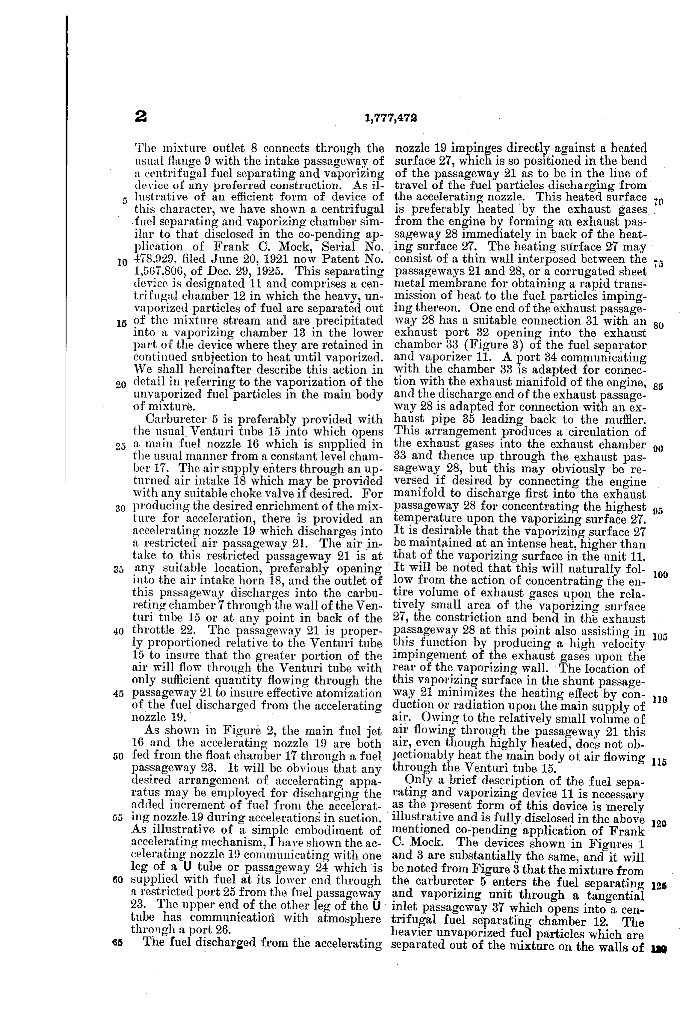
Page 6
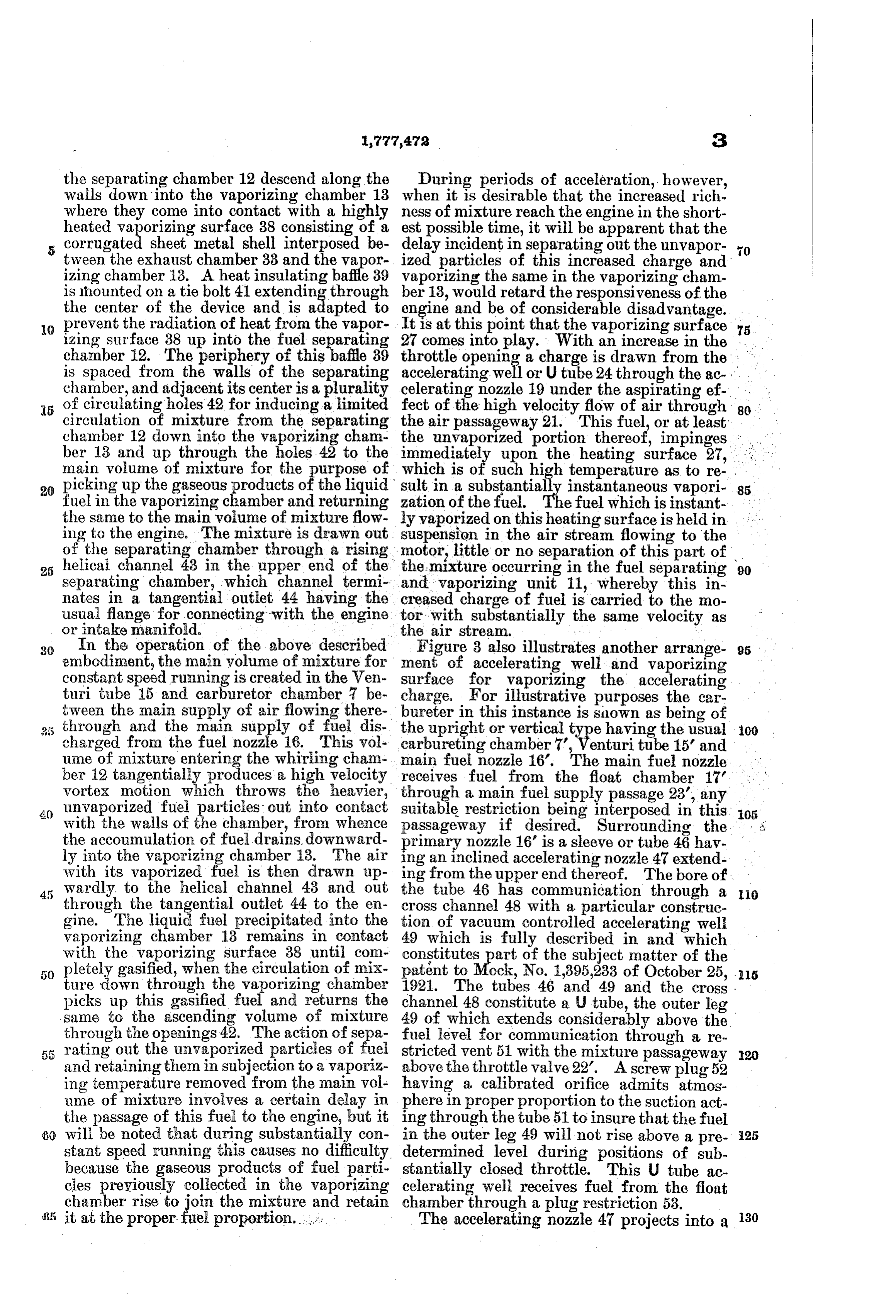
the separating chamber 12 descend along the During periods of acceleration, however, walls down into the vaporizing chamber 13 when it is desirable that the increased rich where they come into contact with a highly ness of mixture reach the engine in the short heated vaporizing surface 38 consisting of a est possible time, it will be apparent that the corrugated sheet metal shell interposed be delay incident in separating out the unvapor 70 tween the exhaust chamber 33 and the vapor ized particles of this increased charge and izing chamber 13. A heat insulating baffle 39 vaporizing the same in the vaporizing cham is hounted on a tie bolt 41 extending through ber 13, would retard the responsiveness of the the center of the device and is adapted to engine and be of considerable disadvantage. prevent the radiation of heat from the vapor It is at this point that the vaporizing surface
izing surface 38 up into the fuel separating 27 comes into play. With an increase in the 75 chamber 12. The periphery of E. 39 throttle opening a charge is drawn from the ... is spaced from the walls of the separating accelerating well or Utube 24through the ac chamber, and adjacent its center is a plurality celerating nozzle 19 under the aspirating ef 5 of circulating holes 42 for inducing a limited fect of the high velocity flow of air through 8 circulation of mixture from the separating the air passageway 21. This fuel, or at least chamber 12 down into the vaporizing cham the unvaporized portion thereof, impinges ber 13 and up through the holes 42 to the immediatel upon the heating surface 27, , main volume of mixture for the purpose of which is of such high temperature as to re. 20 picking up the gaseous products of the liquid sult in a substantially instantaneous vapori 85 fuel in the vaporizing chamber and returning zation of the fuel. efuel which is instant the same to the main volume of mixture flow ly vaporized on this heating surface is held in ing to the engine. The mixture is drawn out suspension in the air stream flowing to the of the separating chamber through a rising motor, little or no separation of this part of 25 helical channel 43 in the upper end of the the mixture occurring in the fuel separating 90 separating chamber, which channel termi and vaporizing unit 11, whereby this in nates in a tangential outlet 44 having the usual flange for connecting with the engine creased charge of fuel is carried to the mo tor with substantially the same velocity as or intake manifold. the air stream.
30 In the operation of the above described Figure 3 also illustrates another arrange embodiment, the main volume of mixture for ment of accelerating well and vaporizing constant speed running is created in the Ven surface for vaporizing the accelerating turi tube 15 and carburetor chamber be charge. For illustrative purposes the car tween the main supply of airflowing there bureter in this instance is sinown as being of 35 through and the main supply of fuel dis the upright or vertical type having the usual 100 charged from the fuel nozzle 16. This vol carbureting chamber 7, Venturi tube 15 and ume of mixture entering the whiring cham main fuel nozzle 16. The main fuel nozzle ber 12 tangentially produces a high velocity receives fuel from the float chamber 17' vortex motion which throws the heavier, through a main fuel supply passage 23, any 40 unvaporized fuel particles out into contact suitable restriction being interposed in this 105. with the walls of the chamber, from whence passageway if desired. Surrounding the the accounulation of fuel drains, downward primary nozzle 16' is a sleeve or tube 46 hav ly into the vaporizing chamber 13. The air ing an inclined accelerating nozzle 47 extend with its vaporized fuel is then drawn up ing from the upper end thereof. The bore of wardly to the helical channel 43 and out the tube 46 has communication through a 0 through the tangential outlet 44 to the en cross channel 48 with a particular construc gine. The liquid fuel precipitated into the tion of vacuum controlled accelerating well vaporizing chamber 13 remains in contact 49 which is fully described in and which with the vaporizing surface 38 until con constitutes part of the subject matter of the 50 pletely gasified, when the circulation of mix paint to Mock, No. 1,395,233 of October 25, .5 ture down through the vaporizing chamber The tubes 46 and 49 and the cross. picks up this gasified fuel and returns the channel 48 constitute a Utube, the outer leg same to the ascending volume of mixture 49 of which extends considerably above the through the openings 42. The action of sepal. fuel level for communication through a re rating out the unvaporized particles of fuel stricted vent 51 with the mixture passageway and retaining them in subjection to a vaporiz above the throttle valve 22. A screw plug 52 ing temperature removed from the main vol having a calibrated orifice admits atmos ume of mixture involves a certain delay in phere in proper proportion to the suction act the passage of this fuel to the engine, but it ing through the tube 51 to insure that the fuel 60 will be noted that during substantially con in the outer leg 49 will not rise above a pre 25 stant speed running this causes no difficulty. determined level during positions of sub because the gaseous products of fuel parti stantially closed throttle. This U tube ac cles preyiously collected in the vaporizing celerating well receives fuel from the float chamber rise to ioin the mixture and retain chamber through a plug restriction 53. it at the proper fuel proportion.... The accelerating nozzle 47 projects into a 30
Page 7
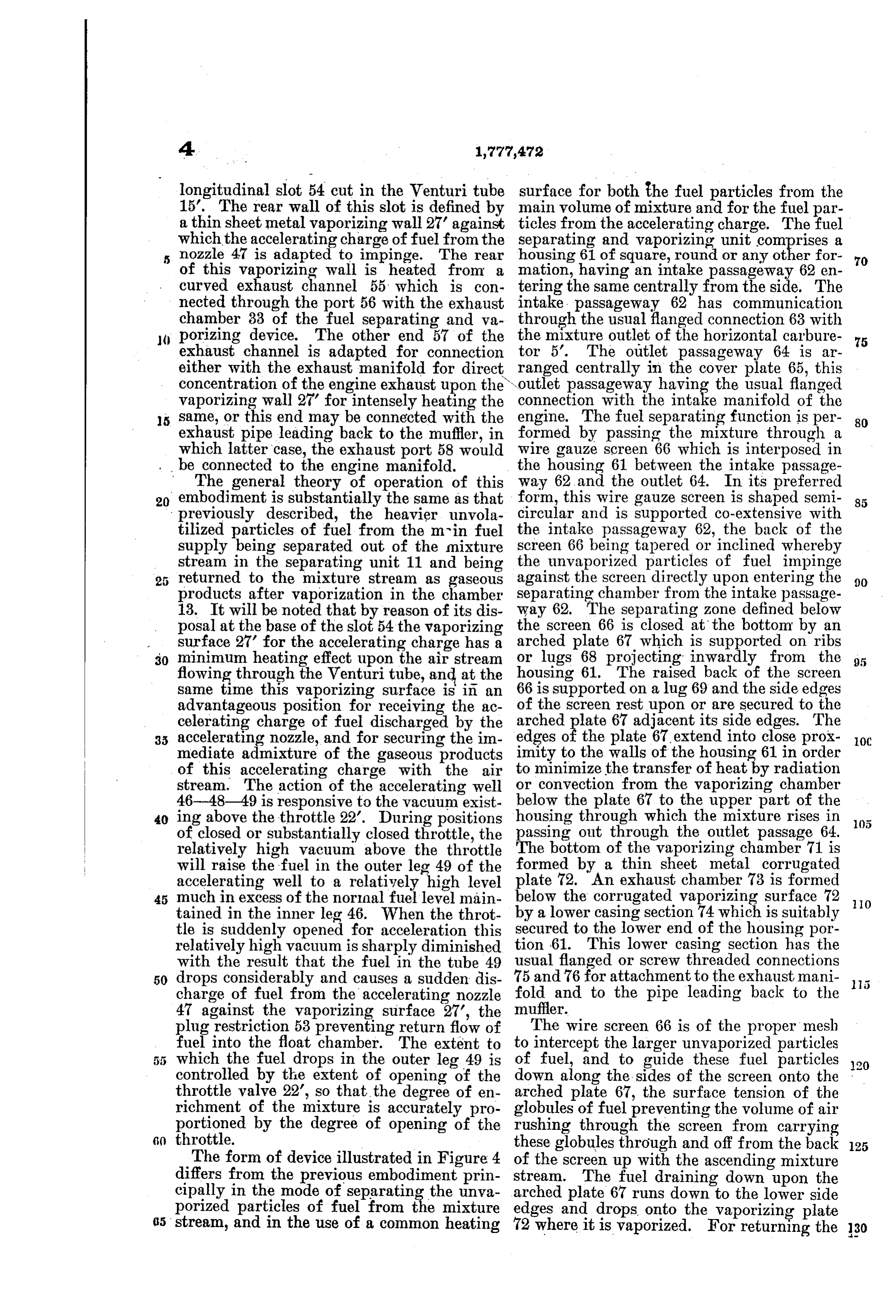
longitudinal slot 54 cut in the Wenturi tube surface for both the fuel particles from the 15. The rear wall of this slot is defined by main volume of mixture and for the fuel par a thin sheet metal vaporizing wall 27' against ticles from the accelerating charge. The fuel which the accelerating charge of fuel from the separating and vaporizing unit comprises a 5 nozzle 47 is adapted to impinge. The rear housing 61 of square, round or any other for of this vaporizing wall is heated from a mation, having an intake passageway 62 en 70 curved exhaust channel 55 which is con tering the same centrally from the side. The nected through the port 56 with the exhaust intake passageway 62 has communication chamber 33 of the fuel separating and va the through the usual flanged connection 63 with () porizing device. The other end 57 of the mixture outlet of the horizontal carbure 5 exhaust channel is adapted for connection tor 5. The outlet passageway 64 is ar either with the exhaust manifold for direct ranged centrally in the cover plate 65, this outlet passageway having the usual flanged concentration of the engine exhaust upon the connection vaporizing wall 27' for intensely heating the with the intake manifold of the 15 Same, or this end may be connected with the engine. The fuel separating function is per 80 exhaust pipe leading back to the muffler, in formed by passing the mixture through a which latter case, the exhaust port 58 would wire gauze screen 66 which is interposed in beThe connected generaltotheory the engine manifold.of this the of operation housing 61 between the intake passage way 62 and the outlet 64. In its preferred 20 embodiment is substantially the same as that form, this wire gauze screen is shaped semi 85 previously described, the heavier unvola circular and is supported co-extensive with tilized particles of fuel from the mrin fuel the intake passageway 62, the back of the supply being separated out of the mixture screen 66 being tapered or inclined whereby the unvaporized particles of fuel impinge stream in the separating unit 11 and being against returned to the mixture stream as gaseous the screen directly upon entering the 90 products after vaporization in the chamber separating chamber from the intake passage 13. It will be noted that by reason of its dis way 62. The separating zone defined below posal at the base of the slot 54 the vaporizing the screen 66 is closed at the bottom by an Surface 27 for the accelerating charge has a arched plate 67 which is supported on ribs 30 minimum heating effect upon the air stream or lugs 68 projecting inwardly from the flowing through the Venturi tube, and at the housing 61. The raised back of the screen same time this vaporizing surface is in an 66 is supported on a lug 69 and the side edges advantageous position for receiving the ac of the screen rest upon or are secured to the celerating charge of fuel discharged by the arched plate 67 adjacent its side edges. The 35 accelerating nozzle, and for securing the im edges of the plate 67 extend into close prox OC mediate admixture of the gaseous products imity to the walls of the housing 61 in order of this accelerating charge with the air to minimize the transfer of heat by radiation stream. The action of the accelerating well or convection from the vaporizing chamber 46-48-49 is responsive to the vacuum exist below the plate 67 to the upper part of the 40 ing above the throttle 22. During positions housing through which the mixture rises in of closed or substantially closed throttle, the passing out through the outlet passage 64. relatively high vacuum above the throttle The bottom of the vaporizing chamber 71 is will raise the fuel in the outer leg 49 of the formed by a thin sheet metal corrugated accelerating well to a relatively high level plate 72. An exhaust chamber 73 is formed 45 much in excess of the normal fuel level main below the corrugated vaporizing surface 72 IO tained in the inner leg 46. When the throt by a lower casing section 74 which is suitably tle is suddenly opened for acceleration this secured to the lower end of the housing por relatively high vacuum is sharply diminished tion 61. This lower casing section has the with the result that the fuel in the tube 49 usual flanged or screw threaded connections 50 drops considerably and causes a sudden dis 75 and 76 for attachment to the exhaust mani fold and to the pipe leading back to the charge of fuel from the accelerating nozzle muffler.
4 against the vaporizing surface 27, the plug restriction 53 preventing return flow of The wire screen 66 is of the proper mesh fuel into the float chamber. The extent to to intercept the larger unvaporized particles which the fuel drops in the outer leg 49 is of fuel, and to guide these fuel particles
controlled by the extent of opening of the down along the sides of the screen onto the 120 throttle valve 22, so that the degree of en arched plate 67, the surface tension of the richment of the mixture is accurately pro globules of fuel preventing the volume of air portioned by the degree of opening of the Tushing through the screen from carrying 6) throttle. these globules through and off from the back 25 The form of device illustrated in Figure 4 of the screen up with the ascending mixture differs from the previous embodiment prin stream. The fuel draining down upon the cipally in the mode of separating the unva arched plate 67 runs down to the lower side porized particles of fuel from the mixture edges and drops onto the yaporizing plate 35 stream, and in the use of a common heating 72 where it is vaporized. For returning the
Page 8
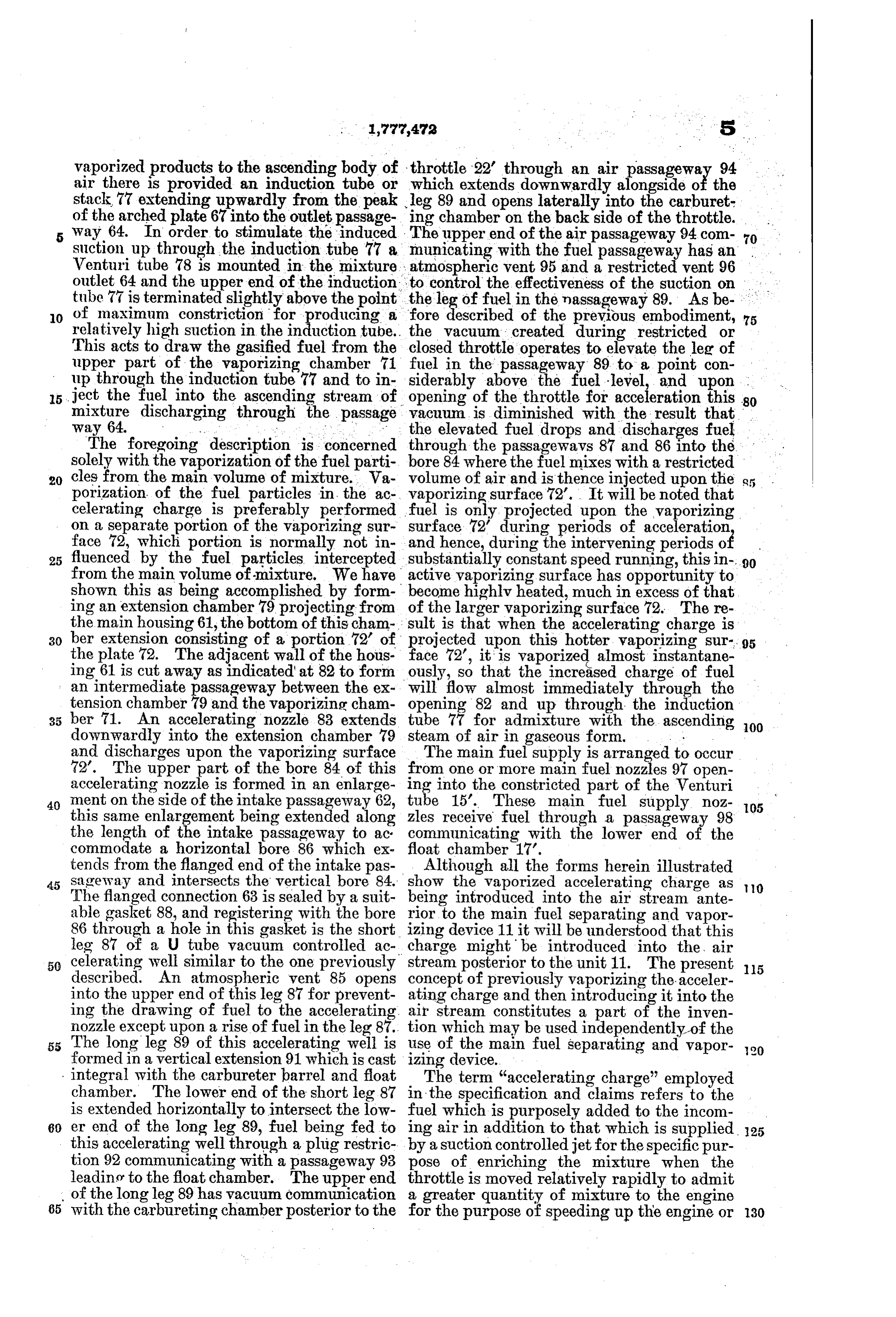
vaporized products to the ascending body of throttle 22' through an air passageway 94 air there is provided an induction tube or which extends downwardly alongside of the stack 77 extending upwardly from the peak leg 89 and opens laterally into the carburet of the arched plate 67 into the outlet passage ing chamber on the back side of the throttle. way 64. In order to stimulate the induced The upper end of the air passageway 94 com 70 suction up through the induction tube 77 a municating with the fuel passageway has an Wenturi tube 78 is mounted in the mixture atmospheric vent 95 and a restricted vent 96 . outlet. 64 and the upper end of the induction. to control the effectiveness of the suction on . . . . tube 77 is terminated slightly above the point the leg of fuel in the nassageway 89. As be 0 of maximum constriction for producing a fore described of the previous embodiment, 75 relatively high suction in the induction tube. the vacuum created during restricted or This acts to draw the gasified fuel from the closed throttle operates to elevate the leg of upper part of the vaporizing chamber 71 fuel in the passageway 89 to a point con up through the induction tube 77 and to in siderably above the fuel level, and upon . 5 ject the fuel into the ascending stream of opening of the throttle for acceleration this 80 mixture discharging through the passage vacuum is diminished with the result that way 64. .. . ... . . . the elevated fuel drops and discharges fuel The foregoing description is concerned through the passagewavs 87 and 86 into the solely with the vaporization of the fuel parti bore 84 where the fuel mixes with a restricted 20 cles from the main volume of mixture. Wa volume of air and is thence injected upon the porization of the fuel particles in the ac vaporizing surface 72’. It will be noted that celerating charge is preferably performed fuel is only projected upon the vaporizing on a separate portion of the vaporizing sur surface 72 during periods of acceleration face 72, which portion is normally not in and hence, during the intervening periodso fluenced by the fuel particles intercepted substantially constant speed running, this in .90 from the main volume of mixture. We have active vaporizing surface has opportunity to shown this as being accomplished by form become highlv heated, much in excess of that ing an extension chamber 79 projecting from of the larger vaporizing surface 72. The re the main housing 61, the bottom of this cham sult, is that when the accelerating charge is 30 ber extension consisting of a portion 72 of projected upon this hotter vaporizing sur 95 the plate 72. The adjacent wall of the hous face 72, it is vaporized almost instantane ing 61 is cut away as indicated at 82 to form ously, so that the increased charge of fuel an intermediate passageway between the ex will flow almost immediately through the tension chamber 79 and the vaporizing cham opening 82 and up through the induction 35 ber 71. An accelerating nozzle 83 extends tube 77 for admixture with the ascending 00 downwardly into the extension chamber 79 steam of air in gaseous form. . . and discharges upon the vaporizing surface The main fuel supply is arranged to occur 72’. The upper part of the bore 84 of this from one or more main fuel nozzles 97 open accelerating nozzle is formed in an enlarge ing into the constricted part of the Venturi 40 ment on the side of the intake passageway 62, tube 15'. These main fuel supply noz 105 this same enlargement being extended along zles receive fuel through a passageway 98 the length of the intake passageway to ac: communicating with the lower end of the commodate a horizontal bore 86 which ex float chamber 17.
tends from the flanged end of the intake pas Although all the forms herein illustrated 45 sageway and intersects the vertical bore 84. show the vaporized accelerating charge as The flanged connection 63 is sealed by a suit being introduced into the air stream ante O able gasket 88, and registering with the bore rior to the main fuel separating and vapor 86 through a hole in this gasket is the short izing device 11 it will be understood that this leg 87 of a U tube vacuum controlled ac charge might be introduced into the air 50 celerating well similar to the one previously stream posterior to the unit 11. The present described. An atmospheric vent 85 opens concept of previously vaporizing the acceler 5 into the upper end of this leg 87 for prevent ating charge and then introducing it into the ing the drawing of fuel to the accelerating. air stream constitutes a part of the inven nozzle except upon a rise of fuel in the leg 87. tion which may be used independently of the 55 The long leg 89 of this accelerating well is use of the main fuel separating and vapor 20 formed in a vertical extension 91 which is cast izing device.
integral with the carbureter barrel and float The term “accelerating charge' employed chamber. The lower end of the short leg 87 in the specification and claims refers to the is extended horizontally to intersect the low fuel which is purposely added to the incom 60 er end of the long leg 89, fuel being fed to ing air in addition to that which is supplied 25 this accelerating well through a plug restric by a suction controlled jet for the specific pur tion 92 communicating with a passageway 93 pose of enriching the mixture when the leadino to the float chamber. The upper end throttle is moved relatively rapidly to admit of the long leg 89 has vacuum communication a greater quantity of mixture to the engine 65 with the carbureting chamber posterior to the for the purpose of speeding up the engine or 30
Page 9
for causing it to exert a greater effort. It is raw liquid fuel in the accelerating charge of well known to those skilled in the art that fuel.
when the throttle is opened quickly there is 3. The method of delivering fuel to an in a tendency for the mixture to grow lean, ternal combustion engine which comprises that is the ratio of gasoline to air often forming a main unheated mixture of fuel and termed the “gas ratio’ decreases. This is air, during acceleration delivering additional due to the fact that air flows more readily fuel to said mixture in a strongly heated con than does the liquid fuel, and the sudden in dition, and at all times subjecting the mixture rush of air does not aspirate a proportion at a point beyond the point of addition of the O ate amount of fuel resulting in a disturbance accelerating charge to centrifugal stratifica 3 of the gas ratio of the normal running mix tion and selective heating of the denser por ture. tions separated.
To counteract this difficulty the art has pro 4. The method of delivering fuel to an in vided means for releasing and discharging ternal combustion engine which comprises 5 into the mixture an additional “accelerating forming a main charge, adding an enriching 80 charge’ over and above what the mere aspi and accelerating charge of fuel upon sudden ration of the additional air will draw from the suction jet and which accelerating charge increase in load, and invariably heating the accelerating charge to greater degree than the has the function of first counteracting the main charge.
20 tendency to grow leaner and second to cause the mixture to become for a short period of ful5.supply
In a carbureter, the combination of a tume abnormally rich. The abnormally rich therewith, achamber, a fuel nozzle connected mixture is desired temporarily for suddenly throttle controlling the same,passageway, mixture discharge air supply
speeding up the automobile, as it is well means for conducting a stream of air past the 25 known that a mixture to give maximum main fuel nozzle and into the mixture pas power should have a higher gas ratio than sageway, accelerating fuel supply means the mixture which is normally employed for leading running. The mixture which is normally mixturefrom the supply chamber to enrich the employed for running should be of a gas for acceleratingmixture in the the discharge passageway engine, said latter means 30 ratio which will give high economy. The being controlled by the rate of opening of the reference in the specification and in the fol throttle, and a heating surface for contacting lowing claims to the accelerating charge or the means for supplying the same or broadly with the fuel supplied to the mixture by the to the function of supplying the additional the main fuelsupply accelerating supply means independently of to the mixture.
35 fuel for accelerating purposes is intended to 6. In a carburetor, exclude mere secondary fuel inlets such as ture passage, a supplemental a main air and fuel mix O are common in the art for increasing the ing in the direction of the main passage extend range of a relatively small primary jet and opening at its ends into said main passage and passage, its air inlet and to include only such devices means for ejecting fuel into the supplemental 40 as introduce accelerating fuel in addition to passage upon acceleration, and means in the 105 that which is supplied solely by aspiration supplemental from a suction controlled nozzle. passage for vaporizing the fuel ejected thereinto.
As above intimated, it will be obvious that 7. In a carburetion apparatus, the combi various changes may be made in the general nation of a normal charge forming device 45 embodiment hereinbefore described without comprising departing from the essence of the invention. a mixture outlet, a passageway, one end of which is We claim: the other end of which is an air inlet, and a suction 1. In carburetion apparatus, the combina for discharging liquid fuel responsive fuel nozzle tion of a mixture passageway, means for pro into the passage 50 ducing a main body of mixture therein, means way, with means for enriching the mixture including an accelerating well for injecting supplied by said charge forming device com 5 prising a separate supplemental passageway an accelerating charge of fuel into said main extending in the direction of the main pas body of mixture, and means for contacting sageway and opening at its ends into said
with and heating said accelerating charge in first passageway and having fuel supply dependently of the main body of mixture. means responsive upon opening of the throt 2. In carburetion apparatus, means for tle to enrich the mixture for accelerating the producing a combustible mixture for normal engine, and having heating means in said sep running, a vaporizing surface removed from arate passageway and substantially out of 80 the path of the main volume of mixture for thermal contact with the normal mixture for 2: vaporizing the raw liquid fuel in said mix heating the liquid fuel supplied by said sepa ture, means for increasing the charge of fuel rate fuel supply means for accelerating the in said mixture upon acceleration, and addi engine.
tional means removed from the path of the 8. In a carburetion device for an internal 65 main volume of mixture for vaporizing the combustion engine, the combination of charge
Page 10
forming means for producing under the suc tion of the engine a mixture stream of air and entrained liquid fuel of a quality suitable for operating the engine continuously at a given speed, said mixture when produced, re quiring vaporization of the entrained liquid, a separator for separating out the entrained unvaporized liquid fuel, said separator hav ing heating means for vaporizing said sepa 0 rated liquid and throwing it back into the charge in the form of vapor, means for intro ducing additional fuel into the stream of mix ture for enriching the mixture for accelerat ing purposes, and heating means for vaporiz 5 ing the unvaporized portion of the additional fuel prior to passage of said additional fuel into the main stream of mixture to permit. said enrichment to pass through said separa tor without delay to secure prompt response 20 of the engine.
9. In carburetion apparatus for an internal combustion engine, the combination of means for forming a running mixture for the engine, a throttle controlling the rate of mixture de livery to the engine, means for adding an en riching and accelerating charge of fuel upon sudden increase in the rate of mixture deliv ery to the engine, and means for invariably heating the accelerating charge to greater de 30 gree than the main charge. .
10. In carburetion apparatus, the combina tion of a mixture passageway, a throttle valve therefor, a main fuel supply chamber, a main fuel inlet from the chamber to said mixture 35 passageway, an accelerating fuel supply chamber fed from the main fuel supply cham ber, a supplementary fuel inlet from said aux iliary fuel supply chamber to said passage way operable upon further opening of the 40 throttle to supply fuel from said accelerating fuel supply chamber, and heating means for contacting with and heating the fuel dis charged from said supplementary fuel inlet independently of the main fuel supply from 45 said main fuel inlet.
11. The combination of a carburetor hav ing a fuel supply chamber, a suction con trolled fuel supply orifice, an accelerating fuel supply chamber having an orifice, and a 50 throttle controlling the rate of delivery from said orifices, of a separate hot spot disposed in position to receive the discharge of accelerat ing fuel from said second orifice only upon sudden opening movement of said throttle 55 for accelerating the engine.
In witness whereof, we hereunto subscribe our names this 30th day of June, 1921.
FRANK C. MOCK.
JOHN A. DIENNER.
Provenance
- Collection
- Cited prior art
- Original PDF
- patentimages.storage.googleapis.com →
- Filed
- 1921-07-05
- Pages
- 10
- Method
- pdftotext (the PDF's own text layer) + pdftoppm 300dpi page scans
- Source
- Google Patents bibliographic record
- Granted
- 1930-10-07
- Inventors
- Frank C Mock; John A Dienner; BENDIX STROMBERG CARBURETOR CO
- Transcribed from
- patentimages.storage.googleapis.com →