patent · US4324289
Environmental heating and cooling apparatus
13 April 1982
Page 1 — bibliographic record
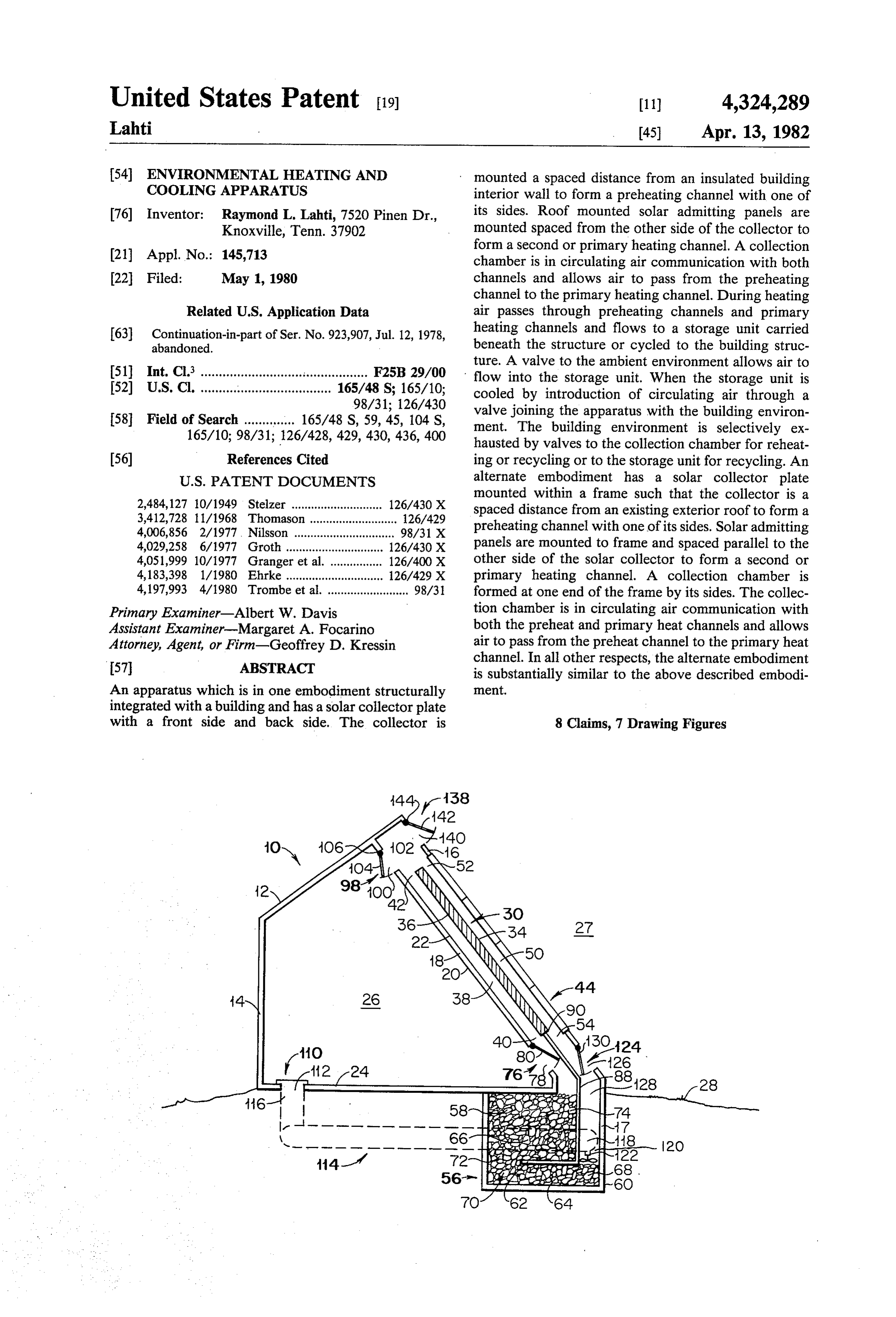
United States Patent (19) 11) 4,324,289 Lahti 45) Apr. 13, 1982 (54) ENVIRONMENTAL HEATING AND mounted a spaced distance from an insulated building COOLINGAPPARATUS interior wall to form a preheating channel with one of 76) Inventor: Raymond L. Lahti, 7520 Pinen Dr., its sides. Roof mounted solar admitting panels are Knoxville, Tenn. 37902 mounted spaced from the other side of the collector to 21 Appl. No.: 145,713 form a second or primary heating channel. A collection chamber is in circulating air communication with both 22 Filed: May 1, 1980 channels and allows air to pass from the preheating channel to the primary heating channel. During heating
Related U.S. Application Data air passes through preheating channels and primary 63 Continuation-in-part of Ser. No. 923,907, Jul. 12, 1978, heating channels and flows to a storage unit carried abandoned. beneath the structure or cycled to the building struc ture. A valve to the ambient environment allows air to 51) Int. Cl. .............................................. F25B 29/00 flow into the storage unit. When the storage unit is 52 U.S. Cl. .......... . . . . . . . . . . . . . . . . . . . . . . . . . . 165/48 S; 165/10; cooled by introduction of circulating air through a 98/31; 126/430 valve joining the apparatus with the building environ 58 Field of Search ........ 165/48 S, 59, 45, 104 S, ment. The building environment is selectively ex 165/10; 98/31; 126/428,429, 430, 436, 400 hausted by valves to the collection chamber for reheat (56) References Cited ing or recycling or to the storage unit for recycling. An
mounted within a frame such that the collector is a 2,484,127 0/1949 Stelzer ............................ 126/430 X spaced distance from an existing exterior roof to form a 3,412,728 11/1968 Thomason ... ... 126/429 preheating channel with one of its sides. Solar admitting 4,006,856 2/1977. Nilsson ........ ... 98/31 X 4,029,258 6/1977 Groth.............. ... 126/430 X panels are mounted to frame and spaced parallel to the 4,051,999 10/1977 Granger et al. . ... 126/400X other side of the solar collector to form a second or 4,183,398 1/1980 Ehrke.............. ... 126/429 X primary heating channel. A collection chamber is 4.197993 4/1986 Trombe at . 98/31 formed at one end of the frame by its sides. The collec Primary Examiner-Albert W. Davis tion chamber is in circulating air communication with Assistant Examiner-Margaret A. Focarino both the preheat and primary heat channels and allows Attorney, Agent, or Firm-Geoffrey D. Kressin air to pass from the preheat channel to the primary heat 57 ABSTRACT channel. In all other respects, the alternate embodiment is substantially similar to the above described embodi
An apparatus which is in one embodiment structurally ment.
integrated with a building and has a solar collector plate with a front side and back side. The collector is 8 Claims, 7 Drawing Figures
Page 2
Drawing sheet — no readable text.
Page 3
Drawing sheet — no readable text.
Page 4
Drawing sheet — no readable text.
Page 5
Drawing sheet — no readable text.
Page 6
duct work and other components which are used in
ENVIRONMENTAL, HEATING AND COOLING addition to those which might commonly go into a APPARATUS building using present construction techniques. A still further object is to provide a system which is relatively
This application is a continuation-in-part of applica inexpensive and maybe installed on existing structures tion Ser. No. 923,907 filed July 12, 1978, and now aban without any need to completely renovate the existing doned. building. With the ever present rising cost of construc This invention relates generally to the use of the tion and all sources of energy, it is another object of this ambient environmental conditions to heat and cool invention to provide an inexpensive system and an en buildings and more particularly to the use of common 10 ergy efficient system which utilizes readily available building elements such as walls, ceilings, floors and solar energy and other ambient environmental condi other structural parts in either existing buildings or tions.
newly constructed buildings to form necessary struc These and other objects and advantages will become tures to control air temperatures and other environmen apparent upon the reading of the following specification tal factors within the building. 15 and drawings wherein:
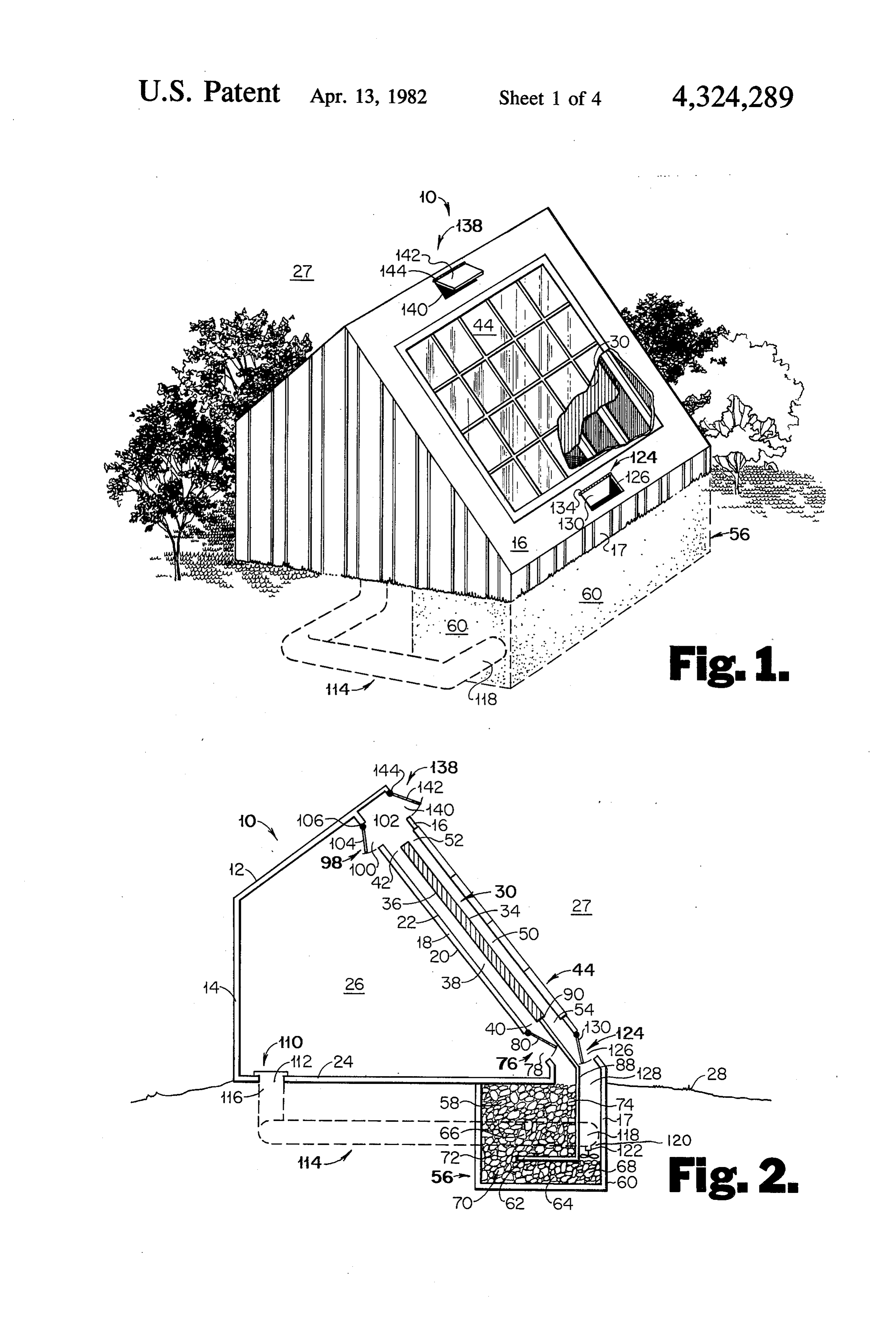
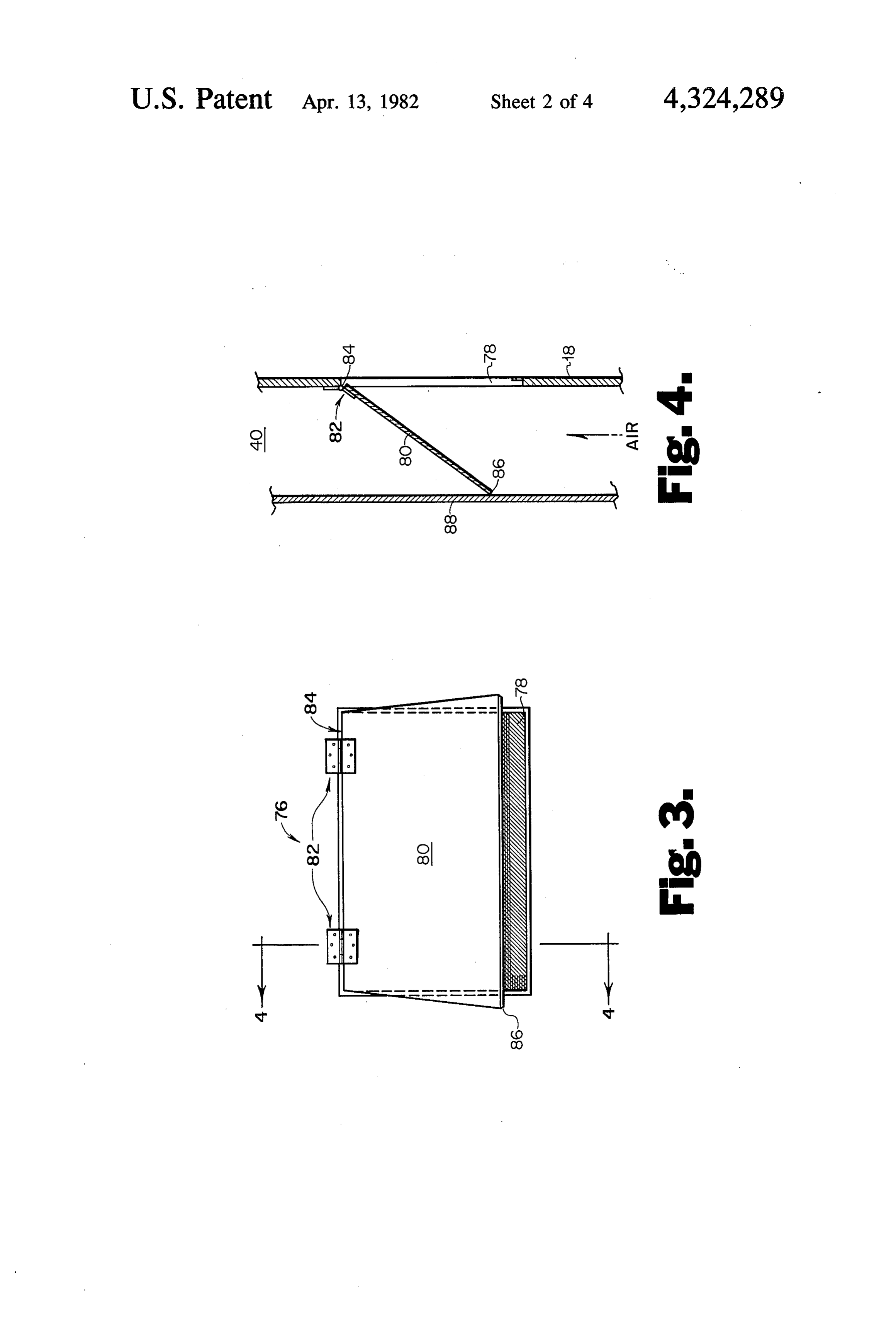
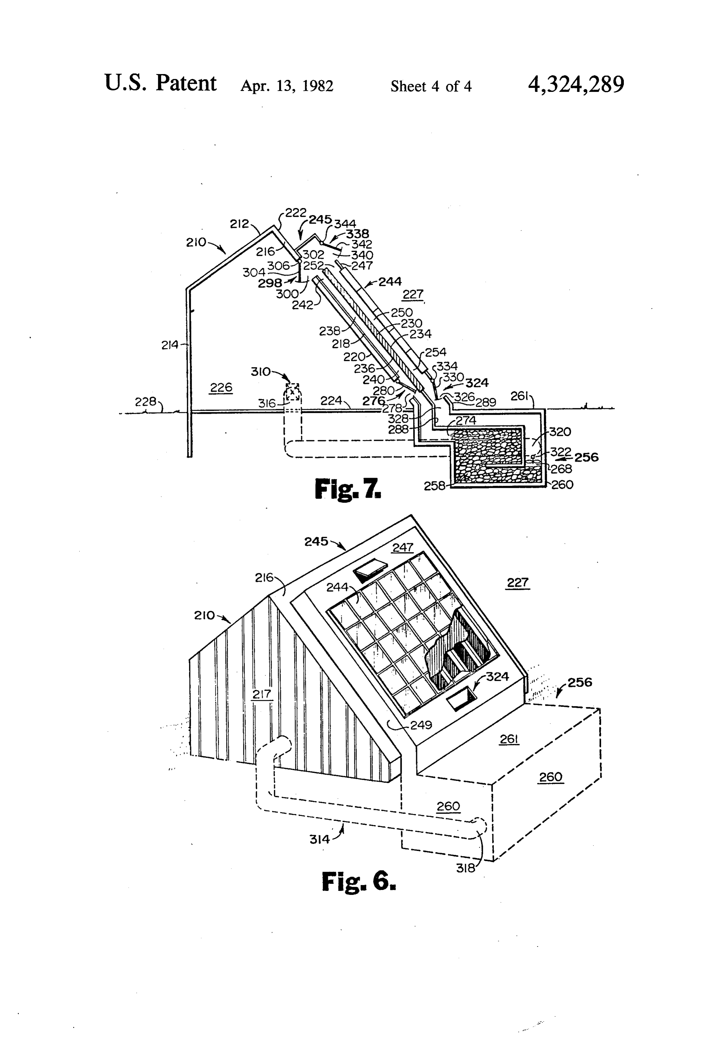
The use of solar energy to heat various building struc FIG. 1 is a prospective view of a structure utilizing tures is well known. Various methods of utilizing solar the features of the present invention with parts broken energy for such purpose have been used. For example, away for purposes of clarity, illustrating a position of one system such as described in U.S. Pat. No. 405,999 the heating system and air handling system. issued to Floyd Randolph Granger on Oct. 4, 1977 20 FIG. 2 is a vertical section through a structure as discloses the use of the attic of a house structure to shown in FIG. 1 utilizing the present invention. collect heated air which is connected to a storage unit FIG. 3 is a view of a typical valve as utilized at vari carried beneath the house structure. When the air in the ous points in the invention shown in FIG. 2 and FIG. 7. attic heated, it is drawn through the ducts by a blower FIG. 4 is a vertical section of FIG. 3 showing a typi and passed through the storage unit. Heat may, at some 25 cal valve.
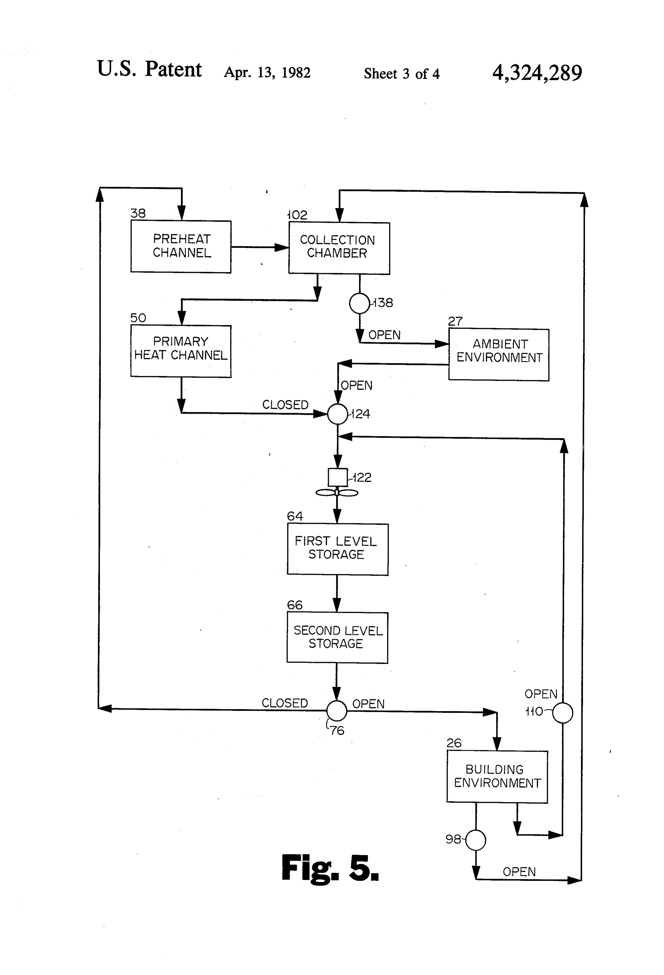
later time, be passed into the house when warming is FIG. 5 is a flow diagram illustrating how the system desired. functions when in operation. Another solar heating apparatus such as described in FIG. 6 is a prospective view of an existing structure U.S. Pat. No. 4,029,258 issued to F. Groth on June 14, utilizing the features of the present invention which is 1977 discloses the use of solar energy to transfer heat 30 added to such structure with parts broken away for from both sides of a collector to circulating air which purposes of clarity, illustrating a position of the heating air is subsequently passed through a storage unit consist and cooling system and air handling system. ing of rocks, which rocks are thereby heated. Again FIG. 7 is a vertical section through existing structure when the ambient conditions are such that the environ as shown in FIG. 6 utilizing the present invention. ment within the structure requires heat, heat is drawn in 35 In accordance with the various features of the inven by use of air from the storage area to the building envi tion, an apparatus for controlling building environment Onnent. by use of circulating air and the ambient environment is Still other art discloses the use of various building provided. The apparatus includes a solar collector hav structures to form channels in which air could be circu ing a frontside and a backside. The collector is oriented lated to carry it from a solar collecting point to a stor 40 with the sun so as to be irradiated when the sun is shin age area for use later. ing. The collector which is heated from the sun irradia However, these various inventions suffered certain tion only on one side, uses both sides as a heating ele disadvantages. Among the various disadvantages was ment. During heating operation, circulating air is passed the fact that some of these systems using air as the trans into a channel and over one side of the collector which fer medium could only absorb a limited amount of heat 45 serves as a preheating means to evaluate or raise the from the collector and transfer it to the storage area. temperature of said air. The preheated circulating air is One of the primary reasons for limited efficiency was then passed through a collection chamber to a primary the fact that the air itself was in contact with the collec heating means or channel which is in heating contact tor for a short period of time. with the other side of the collector and serves to elevate A second similar problem occurred in the storage 50 the temperature over and above the temperature at area in that the air passing through the storage medium tained during preheating. The apparatus is intended to does not come in contact with the air long enough to provide cooling as well as heating and is therefore effect an efficient transfer. equippment with a system for "storing' heat or cold. During the cooling cycle, the storage medium must The heat or cold is transmitted to the storage unit by be cooled by ambient air. However, the drawing of the 55 means of circulating air which may be drawn from the air over the storage medium causes a less than efficient primary heating means in the case of heating or alterna transfer which in turn decreases the efficiency of the tively from the ambient environment in the case of cooling within this so called storage area. cooling. Means is also provided for introducing the It is therefore one object of this invention to provide circulating air from the storage area to either the build a system which increases the efficiency of tranferring 60 ing environment or returning the air to the preheating the heat from the collector. A second object is to pro means for heating. Directing the air to the building vide a more efficient unit for collecting the heat or cold environment or to the preheating means is determined as it is carried in by the air. Another object of this inven by the conditions desired within the building environ tion is to provide a more efficient cooling system. A still ment. In order that the circulating air may move further object is to provide a system which is inexpen 65 through the building environment, means for exhaust sive to manufacture and is subject to be installed in ing are also provided. Said exhausting means directs the structures using conventional construction techniques flow of air from the building environment to the collec without the necessity of large amounts of specialized tion chamber. A second exhausting means directs air
Page 7
flow to the storage means. During the various phases of FIG. 2, is comprised of a medium 58 which is porous operation, a means for circulating the air is provided. and allows air to circulate therethrough. The medium Referring now to the drawings, a structure 10 is 58 may be any suitable material such as by example shown in FIG. 1 and FIG. 2. The structure is equipped stones or rock. The storage unit may be made by exca with a roof 12 and wall 14 which are of conventional vating the ground to form containing walls 60 and plac design. A second roof 16, oriented toward the sun, and ing of the medium 58 in the excavation and covering it second wall 18 within an inner surface 20 and an outer with floor 24. Additional construction above ground on surface 22 is shown and again is constructed in accor said containing walls may be by conventional methods. dance with conventional methods. A floor 24 completes A baffle 62 is placed within the unit 56 so as to divide the essential conveniental elements of the structure. 10 the unit into a lower level 64 and an upper level 66. Roof 12, walls 14 and 18 and floor 24 may be insulated Lower level 64 has an admitting end 68 and an exhaust in accordance with standard building practices of the ing end 74. Circulating air may then be admitted locale in which the structure 10 is located. Additionally, through end 68, passed through lower level 64, and roof 12, walls 14 and 18, and floor 24 define the building exhausted through end 70. End 70 is in circulating air environment 26 of the structure 10. The entire structure 15 communication with end 72. Air, therefore, passes from is situated within an ambient environment 27 which is end 70 into admitting end 72, passes through upper level herein defined to be the weather conditions on any 66, and is exhausted through end 74. As heated or given day. The structure rests on ground 28. cooled air passes through the storage unit 56, the heat or Means for collecting the solar heat is provided. A cold is transferred to the medium 58 and stored for later solar collector 30 is shown in FIG. 1 as a flat plate 20 use. One level storage acts as a primary thermal sink and having a front surface 34 and a back surface 36. The the other level storage acts as a secondary thermal sink. solar collector may be manufactured from a suitable Means is provided for directing the circulating air material such as anodized aluminum and the like which from the storage unit 56 to either the building environ is capable of absorbing solar radiation and becoming hot ment 26 or to the preheating channel 38. As is shown in as the result thereof. The solar collector 30 is disposed 25 FIGS. 5 and 6 as well as FIG. 2, valve 76 may be used in a position parallel to wall 18 but spaced away from for directing the circulating air. An opening 78 through outer surface 22 so as to form a channel 38. The collec wall 18 is provided in order to allow circulating air to tor 30 is additionally oriented so as to receive an opti pass from storage unit 56 from end 74 of said storage mum amount of sun radiation. Channel 38 allow circu unit into said building environment. As a means to re lating air to pass through it from its admitting end 40 to 30 tard or restrict flow through opening 78, cover 80 is its exhausting end 42. As a means of preheating, the shown. Cover 80 as shown in FIGS. 3 and 4 is a substan circulating air passes into channel 38, through admitting tially flat plate and is integrally attached by hinges at 82 end 40 and comes into contact with the back surface 36 along one of its edges to one of the edges 84 of opening of the collector 30 which is heated by the sun. The heat 78. When the cover 80 is in its closed mode, its edges from surface 36 is then transmitted to the circulating air 35 come in air tight contact with edges of opening 78 and which in turn passes through exhausting end 42. Ex restrict air from circulating from end 74 of the storage hausting end 42 is in circulating air communication with unit through opening 78 into building environment 26. a collection chamber 102. Air may therefore be depos Circulating air is then passed from end 74 of the storage ited within said collection chamber. unit to admitting end 40 of the preheating channel 38. To protect the collector from the ambient environ 40 When valve 76 is in its open mode, cover 80 is pivoted ment, solar admitting panels 44 are provided. These about hinges 82 until the edge opposite 84, 86 come into panels are flat with two surfaces. The admitting panels contact with a dividing wall 88 as shown in FIG.3 and 44 are manufactured from a material such as glass, plas FIG. 4. Dividing wall 88 separates channels 38 and 50. tic or the like which will allow the radiation from the One edge of dividing wall 88 is attached to the lower sun to pass through them and strike the collector 30. 45 edge of collector 30 and 90. The other edge of said The panels 44 are disposed with one surface parallel to dividing wall 88 is attached to baffle 62 at 96. Circulat the front surface 34 of collector 30 and attached to roof ing air from end 74 of the storage unit is then directed 16 in such a manner as to form channel 50 between front by cover 80 through opening 78 into the building envi surface 34 of the collector and one surface of panels 44. ronment 26. Additionally, the circulating air is re The other surface of the admitting panels 44 are faced to 50 stricted from flowing into admitting end 40 of the pre the ambient environment 27 and serves as an exterior heating chamber 38. The valve cover 80 is operated cover for structure 10. Channel 50 has an admitting end either manually or by means of a conventional motor, 52 in circulating air communication with collection solonoid or the like which may be controlled for exam chamber 102 and an exhausting end 54. This allows air ple by thermostat or conventional switch. Typically the to be admitted through end 52 of channel 50 from the 55 valve cover 80 could be manufactured from any sub collection chamber, pass through channel 50, and be stantially rigid material such as wood or metal. Hinge exhausted through end 54. As a means of primary heat 82 is any typical conventional hinge.
ing, circulating air is drawn in through end 52 into Means for exhausting the building environment 26 is channel 50. Surface 34 of the collector 30, which has provided. A valve 98 similar to that shown in FIG. 3 been heated by solar radiation, then comes into contact 60 and 4 is shown near the apex of structure 10 in FIG. 2 with the circulating air and thereby transmits heat to it similar to valve 76. The valve 98 is comprised of a open which raises the temperature again. In turn the heated ing 100 through wall 18 similar to opening 78 of valve air is exhausted through end 54. 76. Opening 100 allows circulating air to flow from Conditions in the ambient environment 27 are not building environment 26 through it to collecting cham always the same as those desired within the building 65 ber 102. Valve 98 additionally has a flat cover 104 simi environment 26. Therefore, means for storing heat or lar to cover 80 of valve 76. Cover 104 is pivotally con cold for later use is provided. Such means, designated nected at one of its edges by a hinge at 106 to one side generally as a thermal storage unit 56 in FIG. 1 and of opening 100. When valve 98 is in the open mode,
Page 8
cover 104 is pivoted about the hinge at 106 inwardly of an opening 140 through roof 16 above the solar ad toward environment 26 and away from collecting mitting panels 44. Opening 140 opens into chamber 102. chamber 102. This then allows circulating air to pass This allows circulating air to flow from collecting through opening 100 into chamber 102. When valve 98 chamber 102 through opening 140 into environment 27. is in the closed mode, cover 104 is pivoted such that it The opening 140 is similar to opening 78 of valve 76. A covers opening 100 and restricts circulating air from cover 142 is provided to fit over opening 140. Cover flowing from environment 26 to chamber 102. The 142 is attached by one edge to the edge of opening 140 valve cover 104 may be manufactured from any sub by a hinge at 144 located furthest distance from solar stantially rigid material such as wood or metal. The admitting panels 44. Additionally, cover 142 is attached hinge is a conventional hinge readily available commer 10 in such fashion as to allow said cover 142 to pivot out cially. The valve 98 is operated either manually or by wardly away from collecting chamber 102 about the means of a conventional motor which in turn may be hinge. When valve 138 is in the closed mode, cover 142 controlled by thermostat or other conventional switch. fits over opening 140 and restricts circulating air flow Additional exhausting of building environment may from chamber 102 through said opening to ambient be desired. Therefore another means for exhausting is 15 environment 27. When valve 138 is in the open mode, provided. In this regard, a valve 110 is provided which cover 140 is pivotally rotated about the hinge toward is shown as a conventional register in FIG. 2. An open the ambient environment 27 and away from chamber ing 112 through floor 25 is provided. A duct 114 having 102. Circulating air may flow from chamber 102 a first end 116 is attached to valve 110 through opening through opening 140 into ambient environment 27. The 112 in circulating air communication with environment 20 valve 138 may typically be operated manually or by a 26 of the building. The other end 118 of duct 114 opens motor. Said motor could be activated thermostatically into circulating air communication with admitting end or manually operated switch. The cover 140 itself could 120 by blower 122. Valve 110 covers opening 112 and be manufactured from a rigid material as by example may be selectively opened or closed. When valve 110 is Wood or metal. Again the hinge may by any suitable in the open mode, circulating air may flow from envi 25 commercially available hinge.
ronment 26 thrugh opening 112 into end 116 of duct Air must be circulated through the system. Means for 114, through duct 114 to the admitting end of 120 of circulating the air, therefore, is provided. Such means is blower 122. When valve 110, is selectively closed, cir a conventional blower 122 or the like. Blower 122 is culating air is restricted and prevented from flowing disposed within a space defined by one wall of storage through opening 112. 30 unit 56 and wall 88 and below duct end 118. Air is Air from the ambient environment 27 is sometimes drawn from channel 128 and end 118 of duct 114. Circu desired. Therefore, means for receiving air from the lating air passes through blower 122 and is blown into ambient environment 27 into the circulating air system the admitting end 68 of storage unit 56. Blower 122 is provided by way of valve 124 shown in FIG. 1 and 2 provides means for circulating air throughout the entire and is similar to valve 76. An opening 126 through roof 35 system, Blower 122 is of any conventional design capa 16 is provided near and above ground level 28. To ble of circulating air. Blower 122 may be controlled maximize the efficiency of the system, such opening 126 manually or thermostatically.
is near ground level but need not be. Additionally, the An alternative embodiment of this invention shows opening 126 is oriented to enter below the exhausting an apparatus for controlling building environment by end 54 of primary heating channel 50. The opening 126 40 use of circulating air and the ambient environment is similar to opening 78 of valve 76. Air enters through which apparatus is attached to and used in connection opening 126 into a channel 128 which is defined by wall with existing structures. Referring now to the drawings, 88 and roof 16 and outside wall 17. A cover 130 is pro an existing structure 210 is shown in FIG. 6 and FIG. 7. vided and is attached by means of a hinge at 134 to the As with any conventional house or building, the exist roof 16 at the edge of opening 126 nearest the solar 45 ing structure shows a roof 212 and wall 214. Generally, admitting panels 44. Additionally, the cover 130 is at an existing structure has one portion of its roof which is tached to allow it to pivot about the hinge inwardly into oriented more towards the sun than other portions of channel 128. When valve 124 is in the closed mode, the roof. Therefore, a second roof 216 as part of the cover 130 is shut and restricts flow from the ambient air existing structure is the portion of the existing roof through opening 124 by covering said opening. Circu 50 which is more oriented towards the sun. Roof 216 has lating air is free to move from exhausting end 54 of an inner surface 220 and outer surface 222. A floor 224 primary heating channel 50 into channel 128. When completes the elements that are found in an existing valve 124 is in the open mode, cover 130 is rotated structure. Roof 212 and 216, wall 214 and floor 224 as about the hinge until the edge opposite the hinged edge before stated may be insulated in accordance with vari contacts wall 88 in such fashion as to prevent air from 55 ous standard building practices within a locale to in flowing from exhausting end 54 of primary heating prove the efficiency of this apparatus. Roof 212, walls channel 50. Air is free to flow from environment 27, 214, roof 216, and floor 224 generally define the build through opening 126 into channel 128. Again as before ing or house environment 226 of the existing structure such cover 130 may be manufactured from a rigid mate 210. The existing structure is situated within an ambient rial such as wood or metal. Typically valve 126 may be 60 environment 227 which is the weather conditions on operated manually or by motor as other valves previ any given day. The structure rests on ground 228. ously described. Said motor may be activated by As before, means for collecting the solar heat is pro theremostatic switch or manually operated switch. The vided. A solar collector 230 is shown in FIG. 7 as a flat hinge may be any commercially available hinge. plate having a front surface 234 and back surface 236. Means for exhausting circulating air to the ambient 65 This solar collector as in the first embodiment may be environment 27 is provided. A valve 138 is shown in made from a suitable material which is capable of ab FIG. 1 and FIG. 2 at the apex of the structure 10 and is sorbing solar radiation and becoming hot from such again similar to valve 76. Said valve 138 consists of part radiation. The solar collector 230 is disposed in a posi
Page 9
tion generally parallel to roof 216 within a frame box 280 is substantially similar to cover 80 as shown in 245 to form channel 238 with a bottom 218 of said frame FIGS. 3 and 4 responds and is controlled in a substan box. Frame box. 245 is then mounted to surface 222 of tially similar fashion.
roof 216. The collector 230 is oriented so as to obtain Means for exhausting the building environment 226 is optimum radiation. Channel 238 allows circulating air also provided. A valve 298, similar to that shown valve to pass through it from its admitting end 240 through its 76 in FIGS. 1 and 2 is shown near the apex of structure exhausting end 242. As a means of preheating, as in the 210 in FIG. 7 and is also similar to valve 276. Valve 298 first embodiment, the circulating air is passed into chan is comprised of an opening 300 through roof 216 similar nel 238 through admitting end 240 and while therein to opening 278 at valve 276. Opening 300 allows circu comes in contact with the back surface 236 of collector O lating air to flow from the building environment 226 230 which has been heated by the sun. The heat from through to collecting chamber 302. Valve 298 addition surface 236 is then transmitted to the circulating air ally has a flat cover 304 similar to cover 280 of valve which then in turn passes through exhausting end 242. 276. Cover 304 is pivotally connected at one of its edges Exhausting end 242 is in circulating air communication by a hinge 306 to one side of opening 300. The operation with a collection chamber 302. 15 of valve 298 and the determination of its being open or In order to provide protection and separation of the closed is substantially similar to the control and action solar collector 230 from the environment, solar admit of valve 98 in FIGS. 1 and 2. ting panels 244 are provided. As in the first embodiment Additional exhausting of the building environment these panels are generally flat surfaces and may be man 226 may be desired. Therefore, additional means of ufactured from glass, plastic or the like which material 20 exhausting is provided as before. In this regard a valve will allow radiation from the sun to pass through them 310 is provided in the form of a conventional register in and strike collector 230. Panels 244 are disposed with FIG. 7. An opening through wall 217 is provided. A one surface parallel to the front surface 234 of collector duct 314 having a first end 316 is attached to a valve 310 230 and are held in position by frame box 245. Frame through wall 217 in circulating air communication with box. 245 is constructed in such fashion as to form chan 25 environment 226 of the building. The other end 318 of nel 250 between front surface 234 of the collector and duct 314 opens into circulating air communication with one surface of panels 244. The other surface of panels admitting end 320 by blower 322. Valve 310 covers and 244 are faced to and in contact with ambient environ 316 of duct 314 and may be selectively opened or ment 227 and serve as an exterior cover for frame box closed. When valve 310 is in the open mode, circulating 245. Channel 250 has an admitting end 252 in circulating air may flow from environment 226 into end 316 of duct air communication with Chamber 302 and an exhaust 314, through duct 314 to the admitting end 320 of ing end 254. Chamber 302 is defined by bottom 218, top blower 322. When valve 310 is selectively closed, circu 247 and sides 249 of frame box 245 as shown in FIGS. 6 lating air is restricted and prevented from flowing and 7. This allows air to be admitted through end 252 of through duct 314.
channel 250 from the collection chamber 302, passed 35 As previously shown in the first embodiment it is through channel 250, and be exhausted through end sometimes desirable to draw air from the ambient envi 254. While the circulating air is passing through channel ronment 227. Therefore, means for receiving air from 250, such air comes in contact with surface 234 of col environment 227 into the circulating air system is pro lector 230, which collector has been heated by solar vided by way of valve 324 shown in FIGS. 6 and 7. radiation, and raises the temperature of such circulating 40 Again valve 324 is similar to valve 276. An opening 326 air as the result thereof. The heated air is then exhausted through top 247 of framing box. 245 is provided near and through end 254. above ground level 228. Opening 326 is oriented to As with the apparatus as illustrated in FIG. 1 and enter below the exhausting end 254 of primary heating FIG. 2, the alternate embodiment illustrated in FIG. 6 channel 250. The opening 326 is similar to opening 278 and FIG. 7 uses a thermal storage unit 256 which in all 45 of valve 276. Air from the ambient enters through open respects is constructed in substantially the same fashion ing 326 into channel 328 which is defined by wall 288 as thermal storage unit 56 except that with an existing and side 289 of framing box 245. A cover 330 is pro structure the thermal storage unit 256 is constructed vided and attached by means of a hinge at 334 to fram next to the existing structure rather than under it. Stor ing box 245 at the edge of opening 326 nearest solar age unit 256 is comprised of a storage medium 258 admitting panels 244. This valve 324 functions in a sub which is porous and allows air to circulate there stantially similar fashion to valve 124 in FIG. 2. through. The storage unit may be made by excavating To exhaust circulating air into the ambient environ the ground to form walls 260 and placing medium 258 in ment 227, a means is provided by way of valve 338 the excavation and covering it with top 261. Circulating shown in FIGS. 6 and 7 at the apex of structure 210 and air may then pass through end 268 of the storage unit, 55 is again similar to valve 276. Said valve 338 consists in circulate through the storage unit and exhaust through part of an opening 340 through top 247 of framing box end 274. As heated or cooled air circulates through the 245 above the solar admitting panels 244. Opening 340 storage unit, the heat or cold is transferred to medium opens into and is in air contact with chamber 302. This 258 and stored for later use. allow circulating air to flow from collecting chamber As before, a means is provided for directing the circu 60 302 through 340 into environment 327. The opening 340 lating air from the storage unit 256 to either the building is similar to opening 278 of valve 276. A cover 342 is environment 226 or to the preheating channel 238. As provided to fit over opening 340. Cover 342 is attached shown in FIG. 7, a valve 276 may be used for directing by one edge to the edge of opening 340 by hinge 344 the circulating air. An opening 278 through roof 216 is located furthest distance from solar admitting panels provided in order to allow the air to pass from storage 65 244. Additionally, cover 342 is attached in such fashion 256 from exhaust end 274 of said storage unit into build as to allow said cover 324 to pivot outwardly away ing environment 226. To retard or restrict the flow from the collecting chamber 302 and about the hinge at through opening 278, a cover 280 is provided. Cover 344. Valve 338 operates in substantially similar fashion
Page 10
and is operated in conjunction with the other valves as allows air to flow from the building environment 26 into valve 138 as shown in FIGS. 1 and 2. collection chamber 102. All other valves are in the Air must be circulated through the apparatus as closed mode. Air is drawn through preheat channel 38 shown in FIGS. 6 and 7. Means for circulating the air is where it is heated. The air is then drawn into the collec therefore provided in the form of a conventional blower tion chamber 102. At the same time, air from the build 322 as shown in FIG. 7. The blower shown in FIG. 2 is ing environment 26 is drawn into collection chamber substantially similar to the one shown in FIG. 7 and in 102 through valve 98 and mixes with air from the pre all respects is placed and operated in similar fashion. heat channel 38. The mixed air is then drawn into and To illustrate how the system functions, a flow dia through primary heat channel 50 where it is heated gram is shown in FIG. 5. Therein valves are shown 10 further. Thence, the air is drawn into and through schematically as they are within the actual apparatus. blower 122 and forced into the lower level storage unit As previously discussed, at various times valves are 64. There heat is transferred to the medium 58 and either in the open or closed mode. It will be appreciated forced on into upper level storage 66 where additional by those skilled in the art that the structurally integrated heat from the air is transferred to medium 58. The system shown in FIG. 1 and FIG. 2 functions in the 5 heated air is then carried to valve 76 at which point part same fashion as the add-on unit shown in FIG. 6 and of the air is diverted to the building environment 26 and FIG. 7. Therefore the following cycles are equally the rest to the preheat channel 38 to begin the cycle applicable to both systems even though only one is again. The air diverted to the building environment 26 discussed for purposes of explaining the various cycles in turn heats the surroundings.
of the apparatus during heating or cooling. A first cycle 20 Several different cooling cycles are presented within is to heat the storage medium 58 for use in heating the the system. The first cycles presented is used to store building environment 26 at a later time. All valves are in "cold' for use in cooling the building environment 26 the closed mode which causes a closed loop of circulat when desired. This cycle is commenced when the ambi ing air. Circulating air is preheated in pre-heat channel ent environment 27 is cool which is usually in the eve 38 and then drawn by blower 122 into collection cham 25 ning or early morning hours. Valve 124 is opened which ber 102. From collection chamber 102, air circulates to allows the ambient air to flow into the system. Air is not primary heat channel 50 for its final heating. The heated permitted to flow from the primary heat channel 50. air is drawn by blower 122 from primary heat channel Valve 138 is also opened to allow air to flow from the 50 through blower 122 and forced into the lower level system to the environment 27. All other valves are storage 64. The heat is then transferred to medium 58 30 closed. The blower 122 is activated and draws air in within said lower level 64. The air then circulated to the through valve 124 and pulls it through via blower 122. upper level storage 66 where the heated air deposits The air is then circulated to the lower level storage 64 more heat to medium 58. Thereafter, the air is circu and medium 58 is cooled by the cool air. This air is next lated back to the preheat channel 38 to begin the cycle forced into upper level storage 66 by the blower and the again. To make the heater function, radiation of solar 35 medium 58 there is also cooled. From the upper level collector 30 must occur. As the air continues to cycle storage 66, air is passed through the preheat channel 38 through the system, the medium 58 in storage unit 56 into collection chamber 102. Air is then passed from the continues to heat until the system stabilizes. Thermo collection chamber 102 to the ambient environment 27. static detection of this stabilization might by way of The next cooling cycle is used to cool building envi example be used to control the blower 122. 40 ronment 26 when the ambient environment 27 is hot. During the evening or darkness, for example, or at The medium 58 in the storage unit 56 is already cooled other times, it may be desired to heat building environ as above. Valve 76 is opened to the building environ ment 26. To facilitate this, valve 76 is opened to buildment 26 and circulation to preheat channel 38 is pre ing environment 26 and valve 110 is opened to allow air vented. Valve 110 is opened to allow air to flow from to exhaust from environment 26. All other valves are 45 building environment 26 into the return duct 114 which closed. Thus, the cycle includes drawing air from the in turn deposits the air just above the blower 122 input. building environment 26 by blower 122, through Blower 122 is actuated and air is drawn from the build blower 122 into lower level storage 64. The air is forced ing environment 26 through duct 114 to blower 122. through the lower level 64 and is heated by the medium The air is passed through the blower 122 and forced 58, which medium has been previously heated as in the 50 into lower level storage 64. The air then cooled by the first cycle. The air is then passed through upper level cooled medium 58 and passed into an upper level stor storage 66 and is additionally heated by medium 58. The age 66. The air is cooled further in the upper level 66 heated air is then drawn into the building environment and is then passed into the building environment 26 26 which environment is heated thereby. As the air through valve 76. The cooled air which is circulated cools, it gravitates toward the floor 24 and is drawn out 55 into environment 25 lowers the temperature. As the air of environment 26 through valve 110 to begin the cycle warms, it is exhausted through valve 110 to begin the again. This heating cycle may continue until the me cooling process over again.
dium 58 is storage until 56 becomes too cool to raise the A third cooling cycle is also provided. This cycle is building environment 26. employed when the ambient environment 27 is cool and A third heating cycle for the system is also demon 60 it is desired to cool building environment 26. Valve 124 strated. Heating of the building environment 26 may be is opened to allow cool ambient air to flow into the desired during a time when ambient conditions are such system and restrict air flow from the primary heat chan that the preheat channel 38 and primary heat channel 32 nel 50. Valve 76 is opened to allow air to flow into the are heated by solar collector 30. In turn circulating air building environment 26 and restrict flow to the preheat is heated within said channels. Valve 76 is partially 65 channel 38. Valve 98 is opened to allow air from the closed and thus allows air to circulate from the upper building environment to flow into collection chamber level storage 66 to the building environment 26 and the 102. Valve 138 is opened to allow air from the collec preheat channel 38. Valve 98 is in the open mode and tion chamber 102 to flow to the ambient environment
Page 11
27. Valve 110 is closed. When the blower 122 is actu ing communication with each other whereby one ated, air is drawn through valve 124 into the system and level is a primary thermal sink and the other level forced through the blower 122 into lower storage level is a secondary thermal sink; 64. The cool air cools the medium 58 and then passed to a means for introducing circulating air from a selec upper level storage 66 where further cooling of medium 5 tion of one of the ambient environment and said 58 takes place. The air is then circulated through valve heating means into one of said storage levels; 76 into the building environment 26. As the building a means for introducing circulating air from the other environment cools the warmer air, tends to rise toward level of said storage means to one of a selection of valve 98. It is then drawn through valve 98 into collec the building environment and said heating means; tion chamber 102 from which it is then exhausted 10 a collection chamber for collecting the circulating air through valve 138 to the ambient environment 27. This from the heating means and selectively from the continues until the desired temperature is accomplished. building environment and introducing said air to The blower 122 may be actuated as needed to maintain said heating means and selectively to the ambient the building environment 26 at a desired level. environment;
It will be appreciated by those skilled in the art that 15 a means for selectively introducing circulating air even though one side of the solar collector 30 and solar from said collection chamber to the ambient envi collector 230 has been designated as the preheat channel ronment;
and the other side of each of said solar collectors has a means for selectively exhausting the building envi been designated as the primary heat channel the roles of ronment to said collection chamber; preheat channel and primary heat channel could be 20 a means for selectively exhausting the building envi interchanged by reversing the flow of the circulating air ronment to one level of said storage means; and through the apparatus. a means for circulating the air. While a preferred embodiment of the invention has 3. The apparatus of claim 2 wherein said solar heating been described using specific terms, such description is means includes a solar collector with a front side and a for illustrative purposes only, and it will be recognized 25 back side and further comprising a preheating channel by those skilled in the art that changes and variations for preheating the circulating air in heating contact may be made without departing from the spirit and with one of said sides of said solar collector and a pri scope of the following claims. mary heating chamber for heating the circulating air in What is claimed is: heating contact with the other side of said solar collec 1. An apparatus for controlling building environment 30 tor.
by use of circulating air and the ambient environment 4. The apparatus of claim 1 wherein one side of said comprising: preheating channel is formed by said solar collector, a solar collector with a front side and back side; said preheating channel having an admitting and an a preheating channel for preheating the circulating exhausting end, whereby the circulating air enters said air which is in heating contact with one of said 35 preheating channel through said admitting end, the sides of said solar collector; circulating air is heated by said solar collector, and the a primary heating channel for heating circulating air heated circulating air is exhausted through said exhaust which is in heating contact with the other of said ing end.
sides of said collector; 5. The apparatus of claim 1 wherein one side of said a collection chamber for collecting circulating air 40 primary heating channel is formed by said solar collec from a selection of one of the building environment tor, said primary heating channel having an admitting and the preheating channel and distributing the air end and an exhausting end, whereby the circulating air to the primary heating channel and selectively to enters said channel through said admitting end, the the ambient environment; circulating air is heated by said solar collector, and the a means for selectively introducing air from said col 45 heated circulating air is exhausted through said exhaust lection chamber into the ambient environment; ing end.
a means for storing the heat or cold from the circulat 6. The apparatus of claim 1 wherein said storage ing air; means includes rocks for absorbing heat or cold. a means for introducing the circulating air to said 7. The apparatus of claim 2 wherein said storage storing means from one of a selection of ambient 50 means includes rocks for absorbing heat or cold. environment air and air from the primary heating 8. The apparatus claimed in claim 1 wherein said solar channel; collector, said preheating channel, said primary heating a means for introducing the circulating air from the channel, said collection chamber, said means for selec storage means to one of a selection of the building tively introducing air from said collection chamber into environment and said preheating channel; 55 the ambient environment, said means for introducing a means for selectively exhausting the circulating air the circulating air to said storage means from one of a from the building environment to said collection selection of ambient environment air and air from the chamber; primary heating channel, said means for introducing the a means for selectively exhausting the circulating air circulating air from the storage means to one of a selec from the building environment to said storage 60 tion of the building environment and said preheating means; and channel, said means for selectively exhausting the circu a means for circulating the air. lating air from the building environment and said col 2. An apparatus for controlling building environment lection chamber and said means for selectively exhaust by use of circulating air and the ambient environment ing the circulating air from the building environment to comprising: 65 said storage means are contained within a framing a means for solar heating the circulating air; means whereby said framing means is mounted to a a means for storing heat and cold having a lower building structure.
storage level and upper storage level in air circulat sk : :k sk sk
Provenance
- Collection
- Cited prior art
- Original PDF
- patentimages.storage.googleapis.com →
- Filed
- 1980-05-01
- Pages
- 11
- Method
- pdftotext (the PDF's own text layer) + pdftoppm 300dpi page scans
- Source
- Google Patents bibliographic record
- Granted
- 1982-04-13
- Inventors
- Raymond L. Lahti
- Transcribed from
- patentimages.storage.googleapis.com →