patent · US6095121
Evaporated fuel treatment device of an engine
1 August 2000
Page 1 — bibliographic record
United States Patent (19) 11 Patent Number: 6,095,121 Osanai (45) Date of Patent: Aug. 1, 2000 54 EVAPORATED FUELTREATMENT DEVICE 5,735,255 4/1998 Farmer et al.. OF AN ENGINE 5,746,187 5/1998 Ninomiya................................ 123/520 5,884,609 3/1999 Kawamoto . ... 123/520 75 Inventor: Akinori Osanai, Susono, Japan 5,909,726 6/1999 Kobayashi .............................. 123/520 5,909,727 6/1999 Naragawa ............................... 123/520 73 Assignee: Toyota Jidosha Kabushiki Kaisha, 5,921,222 7/1999 Freenano ................................. 123/520 Aichi-ken, Japan FOREIGN PATENT DOCUMENTS
21 Appl. No.: 09/157,722 5223021 8/1993 Japan.
22 Filed: Sep. 21, 1998 7269419 10/1995 Japan. 30 Foreign Application Priority Data OTHER PUBLICATIONS Sep. 22, 1997 JP Japan .................................... 9-256792 U.S. Ser. No. 403,097, Akinori Osanai, filed Mar. 13, 1995. Jan. 30, 1998 JP Japan .................................. 1O-O19567 U.S. Ser. No. 548,887, Akinori Osanai, filed Oct. 26, 1995. (51) Int. Cl. ............................................... F02M 33/02 U.S. Ser. No. 910,245, Akinori Osanai, filed Aug. 13, 1997. 52 U.S. Cl. ............................................. 123/520; 123/357 U.S. Ser. No. 984,326, Akinori Osanai, filed Dec. 3, 1997. 58 Field of Search ..................................... 123/518, 519, Primary Examiner-Carl S. Miller 123/520,521, 516, 357 Attorney, Agent, or Firm-Kenyon & Kenyon 56) References Cited 57 ABSTRACT
5,251,592 10/1993 Seki ........................................ 123/520 control valve for controlling an amount of fuel vapor fed into 5,611,320 3/1997 Hara et al.. the intake passage from a charcoal canister, wherein the 5,634,454 6/1997 Fujita. preSSure in the fuel vapor chamber of the canister is detected 5,655,507 8/1997 Kawasaki. and wherein the vapor concentration, which is one of the 5,676,118 10/1997 Saito ....................................... 123/520 values for correction of the amount of fuel injection, is 5,680,849 10/1997 Morikawa ............................... 123/520 increased when the preSSure in the fuel vapor chamber 5,685.285 11/1997 Ohtani, et al.. increases while the purge operation is stopped.
5,727,537 3/1998 Nakagawa et al.. 27 Claims, 48 Drawing Sheets
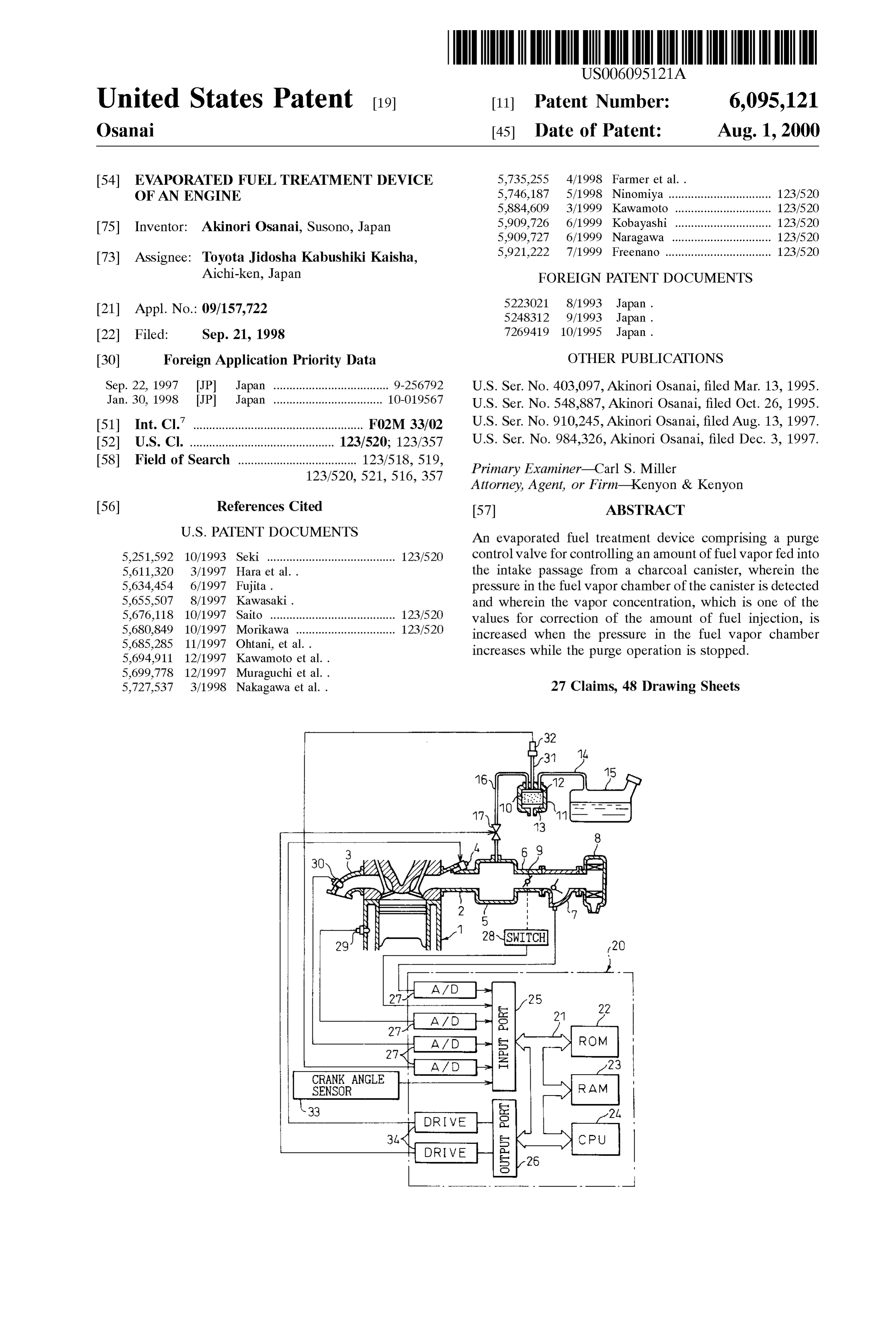
CRANK ANGLE.
SENSOR RAM 33 2L,
DRIVE
Page 2
Drawing sheet — no readable text.
Page 3
Drawing sheet — no readable text.
Page 4
Drawing sheet — no readable text.
Page 5
CALCULATION TIME
OF DUTY RATIO
IS PURGE
CONDITION 1
SATISFIED
INITIALIZING
IS PURGE
CONDITION 2
SATISFIED
53 CALCULATION OF FULL
OPEN PURGE RATE
DK FAF 85
DETERMINE RESTART PURGE RATE
CALCULATION OF CALCULATION OF
57 TARGET PURGE RATE TARGET PURGE RATE
Page 6
Drawing sheet — no readable text.
Page 7
Fig. 7
PURGE CONTROL WALWE
DRIVING PROCESSING
OUTPUT PERIOD
OF DUTY RATIO
TDP G =T IMER
Y EVP of f
TDP G = DPG +TIMER
TO END
Page 8
Fig. 8
FEEDBACK
PROCESSING PROCESSING
YES
Fafav- FAFLFAFR
SKIP FLAG IS SET
FAF -e- FAF + K
FAF IS GUARDED BY 1.2,0.8
TO LEARNING ROUTINE OF AIR-FUEL RATIO
Page 9
LEARNING OF
AIR-FUEL RATIO
NO LEARNING
CONDITION
YES
SKIP FLAG IS RESET 122
YES TO LEARNING ROUTINE OF
WAPOR CONCENTRATION
FAFA Vs O.98
DURING START YES
PROCESSING
CALCULATION ROUTINE OF
FUEL INJECTION TIME
Page 10
Drawing sheet — no readable text.
Page 11
Drawing sheet — no readable text.

Page 12
Drawing sheet — no readable text.
Page 13
Drawing sheet — no readable text.
Page 14
Drawing sheet — no readable text.
Page 15
Drawing sheet — no readable text.
Page 16
Drawing sheet — no readable text.
Page 17
Drawing sheet — no readable text.
Page 18
Drawing sheet — no readable text.
Page 19
Drawing sheet — no readable text.
Page 20
Drawing sheet — no readable text.
Page 21
Drawing sheet — no readable text.
Page 22
Drawing sheet — no readable text.
Page 23
Drawing sheet — no readable text.
Page 24
Drawing sheet — no readable text.
Page 25
Drawing sheet — no readable text.
Page 26
Drawing sheet — no readable text.
Page 27
Drawing sheet — no readable text.
Page 28
Drawing sheet — no readable text.
Page 29
Drawing sheet — no readable text.
Page 30
Drawing sheet — no readable text.
Page 31
Drawing sheet — no readable text.
Page 32
Drawing sheet — no readable text.
Page 33
Drawing sheet — no readable text.
Page 34
Drawing sheet — no readable text.
Page 35
Drawing sheet — no readable text.
Page 36
Drawing sheet — no readable text.
Page 37
Drawing sheet — no readable text.
Page 38
Drawing sheet — no readable text.
Page 39
Drawing sheet — no readable text.
Page 40
Drawing sheet — no readable text.
Page 41
Drawing sheet — no readable text.
Page 42
Drawing sheet — no readable text.
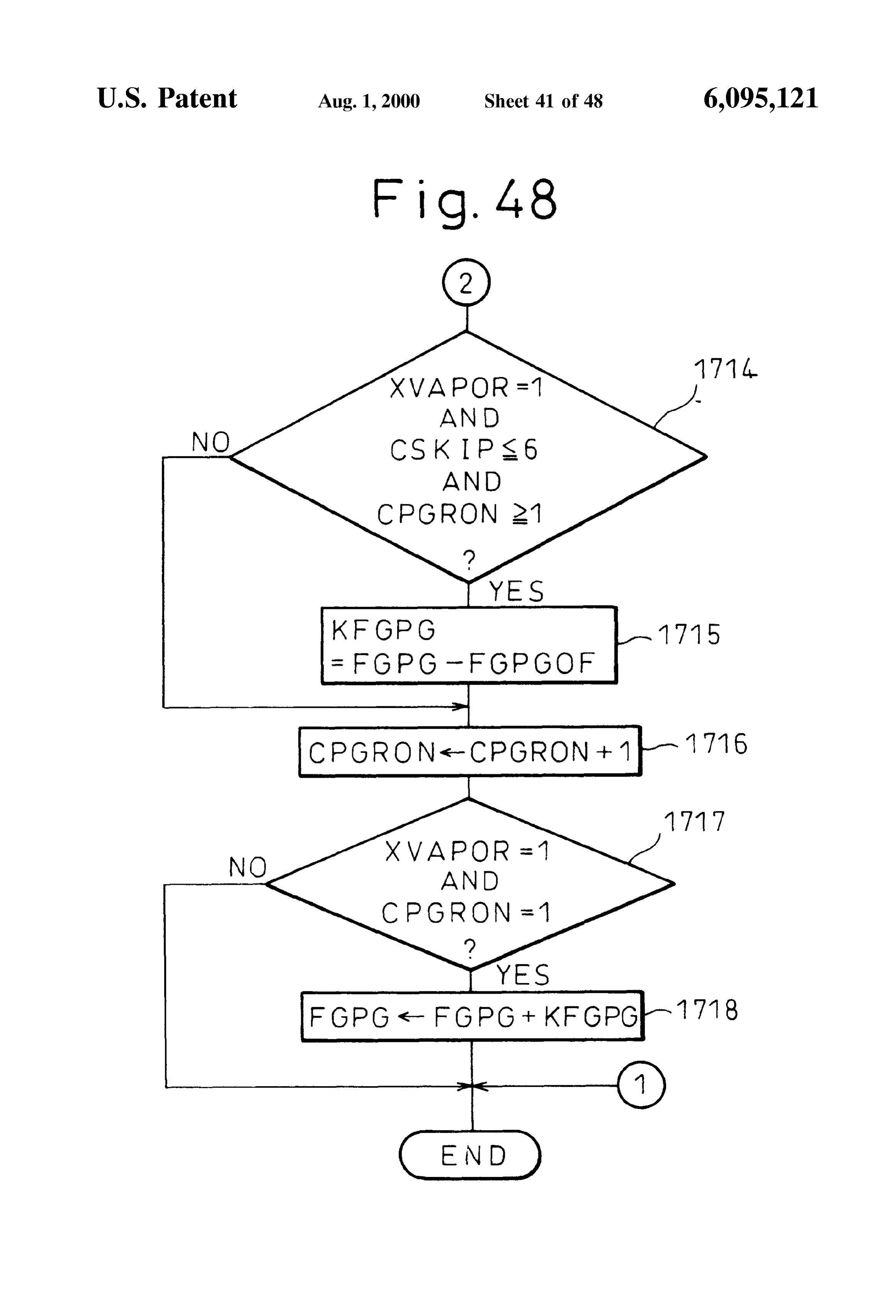
Page 43
Drawing sheet — no readable text.
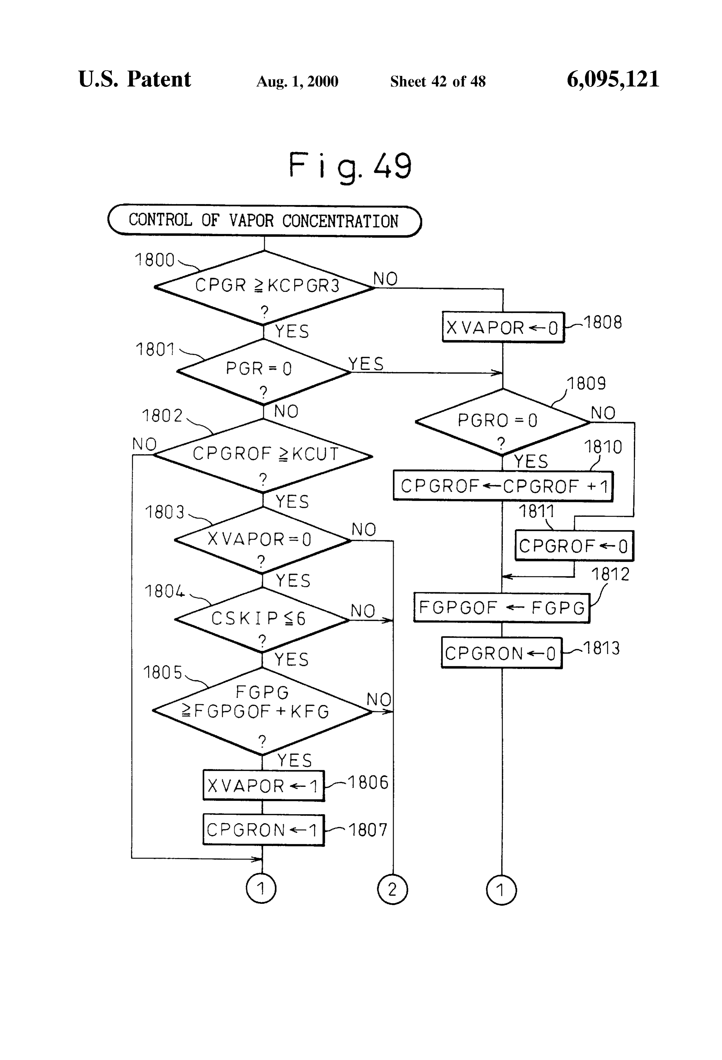
Page 44
Drawing sheet — no readable text.
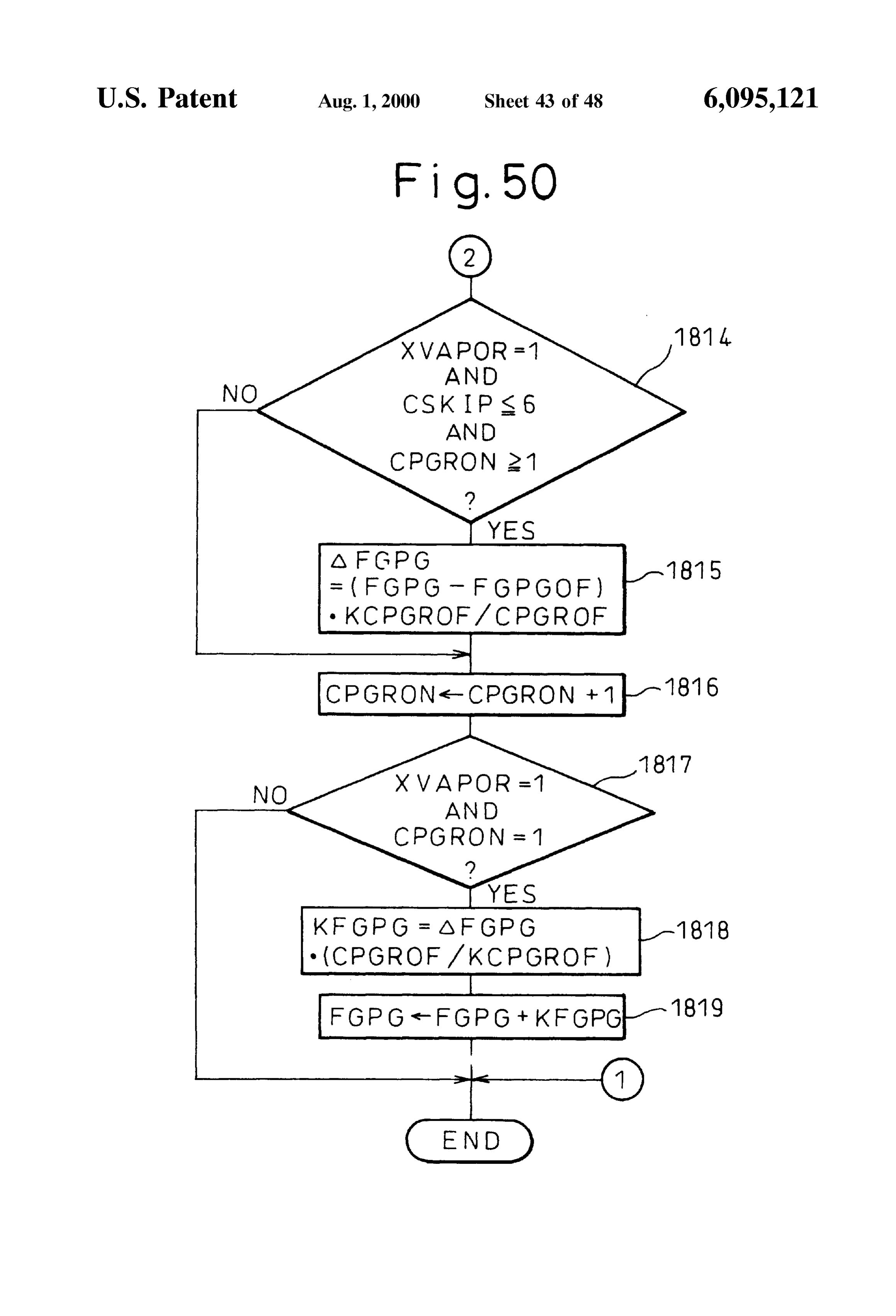
Page 45
Drawing sheet — no readable text.
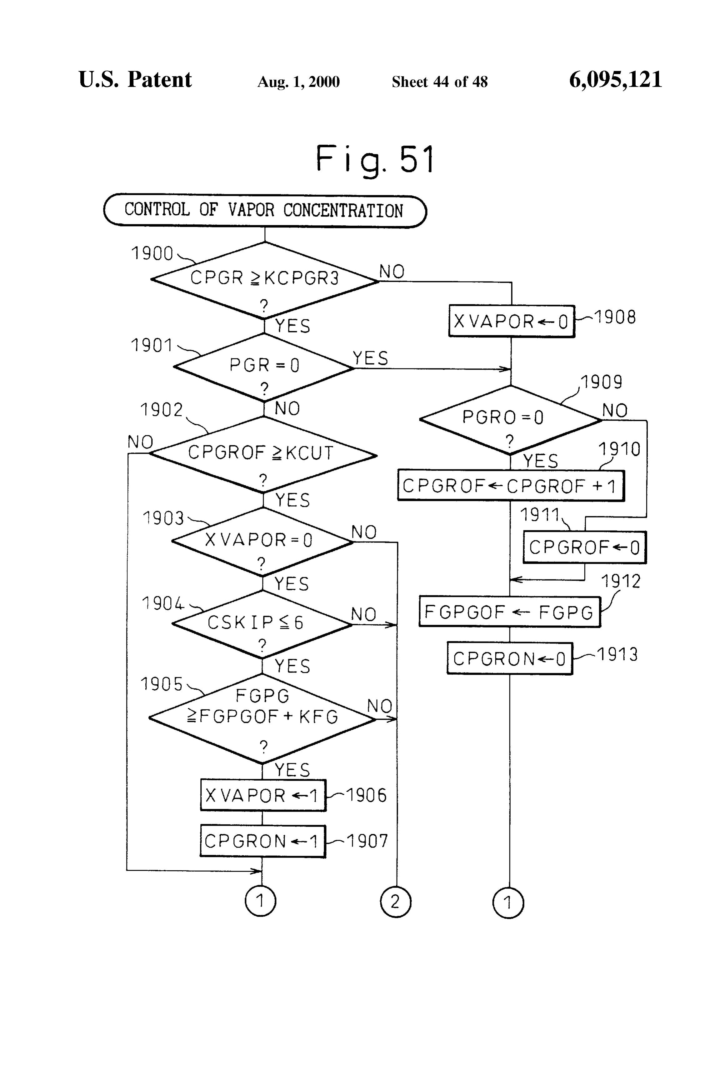
Page 46
Drawing sheet — no readable text.
Page 47
Drawing sheet — no readable text.
Page 48
Drawing sheet — no readable text.
Page 49
Drawing sheet — no readable text.
Page 50
EVAPORATED FUELTREATMENT DEVICE air-fuel ratio from fluctuating when the purge operation of OF AN ENGINE fuel vapor is started again after the purge operation of fuel BACKGROUND OF THE INVENTION Vapor is temporarily Stopped.
1. Field of the Invention According to the present invention, there is provided an evaporated
The present invention relates to an evaporated fuel treat With an intake fuel treatment device for an engine provided ment device of an engine. passage, comprising a purge passage of fuel 2. Description of the Related Art Vapor connecting an upper Space of a fuel tank and the intake Known in the art is an internal combustion engine pro Sage, air-fuel ratiocontrol passage, a purge Valve arranged in the purge pas detecting means for detecting an air-fuel
Vided with a canister for temporarily Storing evaporated fuel ratio; first fuel Supply correcting means for controlling an generated in a fuel tank and a purge control valve for controlling the amount of purge of the fuel vapor to be amount of fuel Supply based on an air-fuel ratio detected by purged from the canister to the inside of an intake passage, the air-fuel ratio detecting means So that an air-fuel ratio which Stores in advance the relationship between the amount becomes a target air-fuel ratio, vapor concentration calcu of evaporated fuel absorbed in the canister and the concen 15 lating means for calculating a vapor concentration of fuel tration of the vapor in the intake passage when the purge Vapor Supplied to the intake passage from an amount of action is being performed, finds the initial concentration of deviation of the air-fuel ratio from the target air-fuel ratio; Vapor immediately after the Start of the purge from the Second fuel Supply correcting means for correcting the amount of deviation of the air-fuel ratio, uses the above amount of fuel Supply based on the vapor concentration So relationship Stored in advance to find the initial amount of that the air-fuel ratio becomes the target air-fuel ratio; and absorbed evaporated fuel of the canister from the initial concentration change detecting means for detecting a change concentration of vapor, then finds the amount of reduction of of vapor concentration of fuel vapor occurring at one of a the amount of absorbed evaporated fuel of the canister per purge passage from the upper Space of the fuel tank to the unit time from the initial concentration of vapor, then uses purge control valve and the upper space of the fuel tank the relationship Stored in advance to predict the concentra while a purge operation is Stopped; one of the first fuel tion of vapor from the reduced amount of absorbed evapo 25 Supply correcting means and the Second fuel Supply correct rated fuel of the canister, finds the amount of reduction of the ing means correcting the amount of fuel Supply in accor amount of absorbed evaporated fuel of the canister per unit dance with a change in the vapor concentration So that the time once again from the predicted concentration of vapor, air-fuel ratio immediately after the purge is restarted then uses the relationship Stored in advance to predict the becomes the target air-fuel ratio.
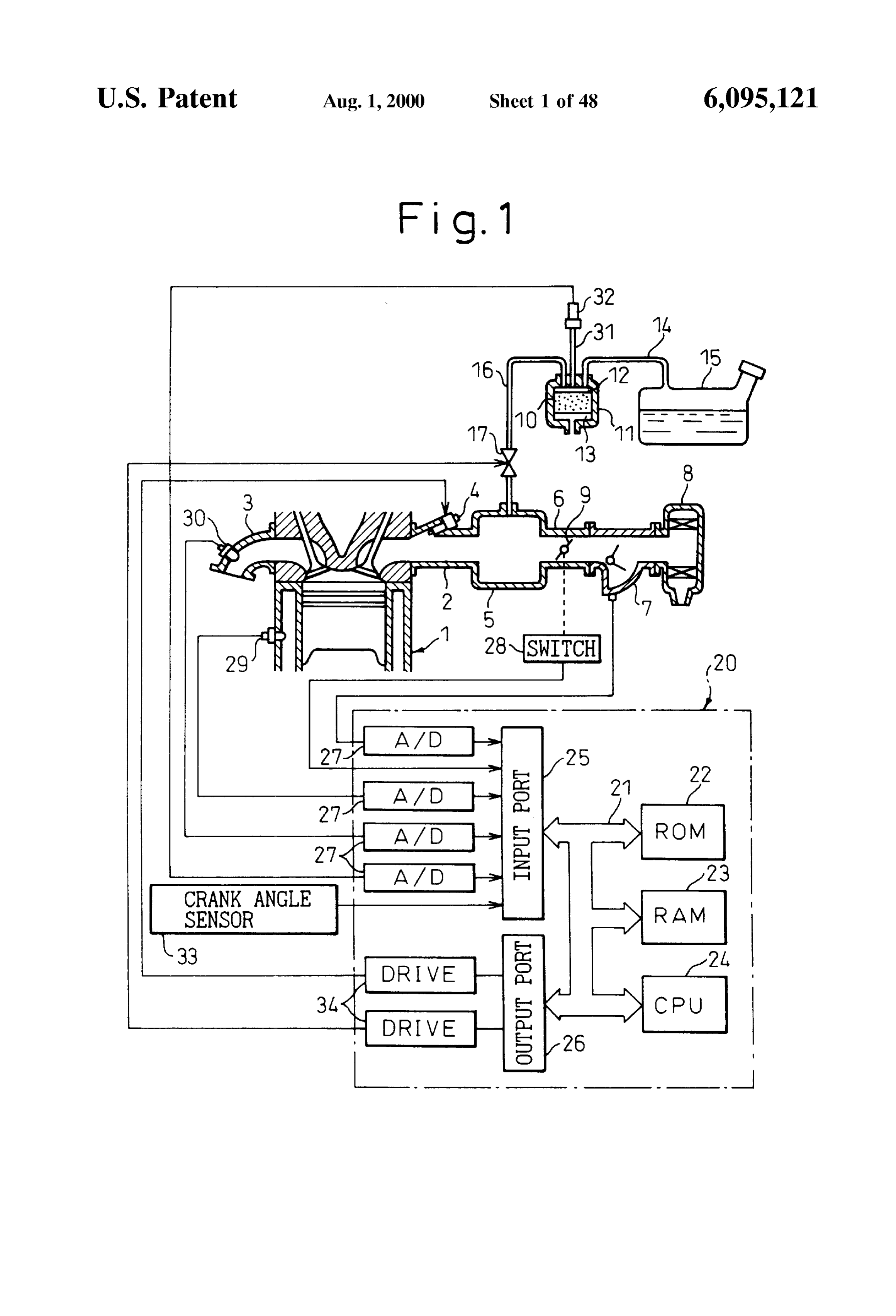
concentration of vapor once again from the reduced amount of absorbed evaporated fuel of the canister, and corrects the BRIEF DESCRIPTION OF THE DRAWINGS amount of fuel Supplied based on the predicted concentra tion of vapor So that the air-fuel ratio becomes a target theThe present invention may be more fully understood from description of preferred embodiments of the invention air-fuel ratio (see Japanese Unexamined Patent Publication Set forth below together with the accompanying drawings, in (Kokai) No. 5-248312). 35 which:
That is, in transitional operation, Sometimes the air-fuel FIG. 1 is an overall view of an internal combustion ratio fluctuates despite the concentration of vapor not chang engine;
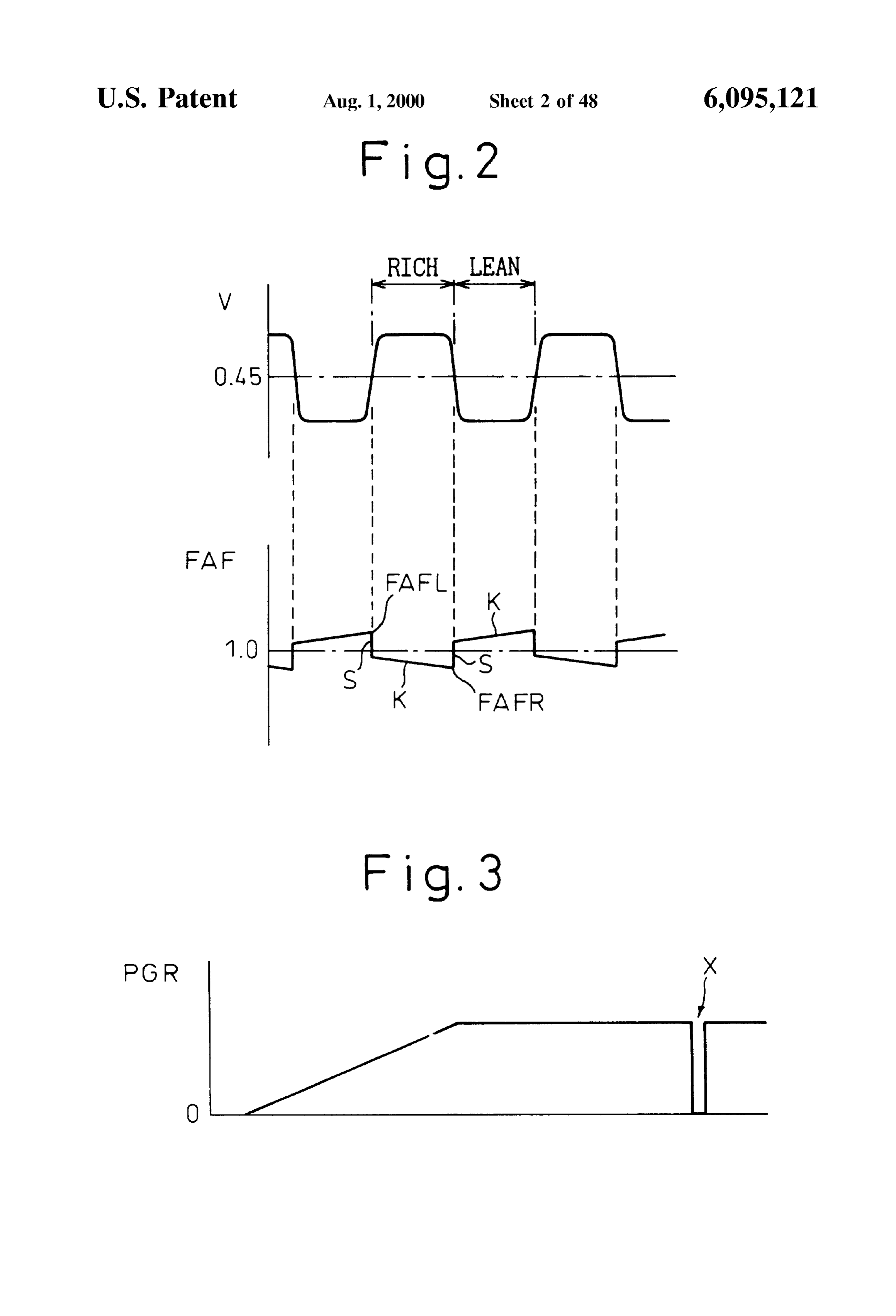
ing. If however the concentration of vapor is calculated based on the amount of deviation of the air-fuel ratio, it is FIG. 2 is a view of the changes in a feedback correction judged that the concentration of vapor has changed even in 40 coefficient FAF:
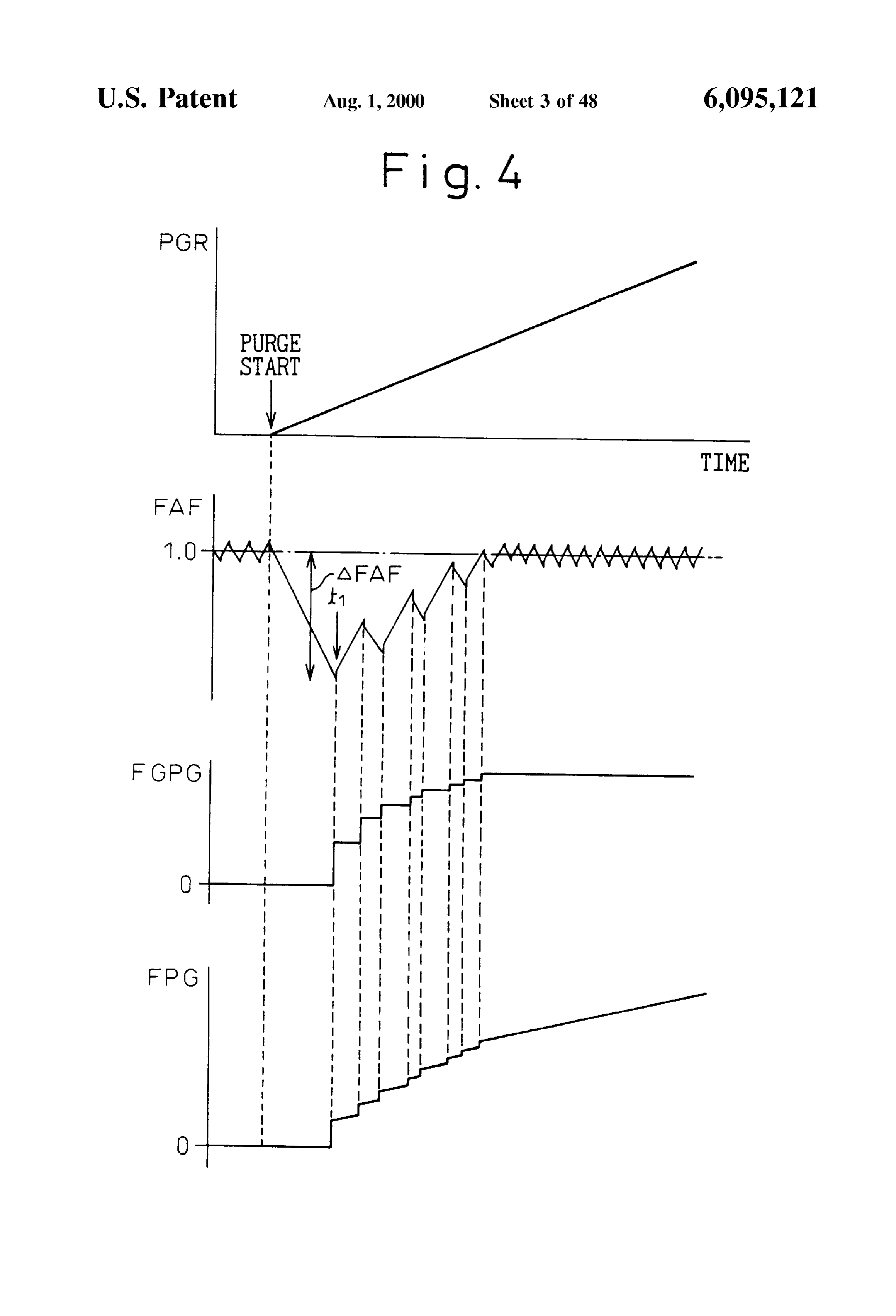
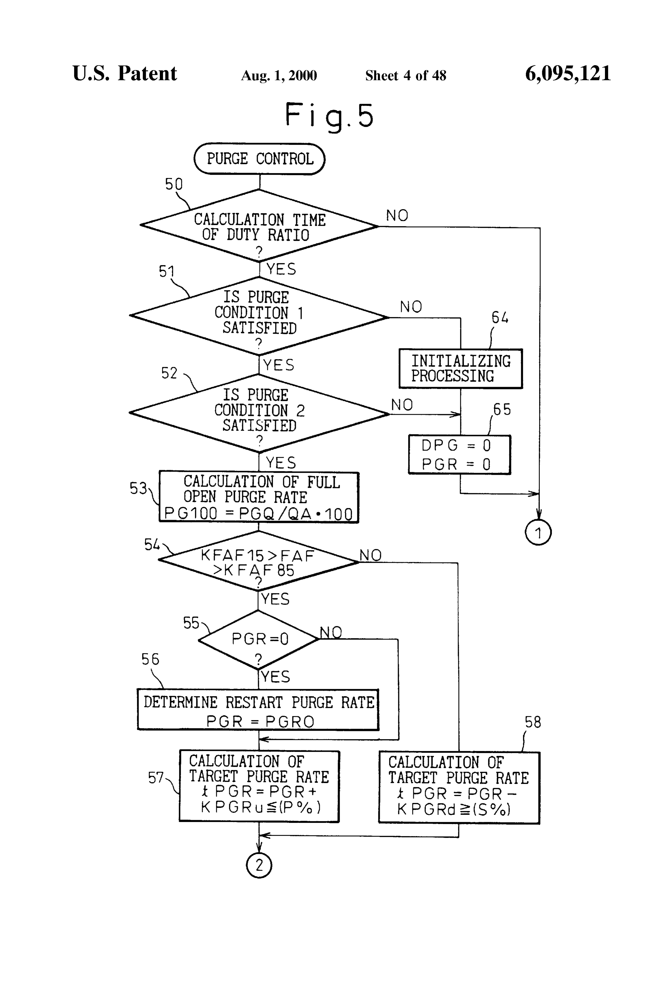
Such a case. If the concentration of vapor is updated at this FIG. 3 is a view of changes in a purge rate PGR: time, the air-fuel ratio will conversely fluctuate. Therefore, FIG. 4 is a view of changes in the feedback correction in the above internal combustion engine, it is assumed that coefficient FAF etc. at the time of Start of a purge action; the amount of absorbed evaporated fuel of the canister FIGS. 5 and 6 are flow charts of purge control; gradually falls after the purge action has started and, based 45 FIG. 7 is a flow chart of processing for driving a purge on this assumption, it is predicted that the concentration of
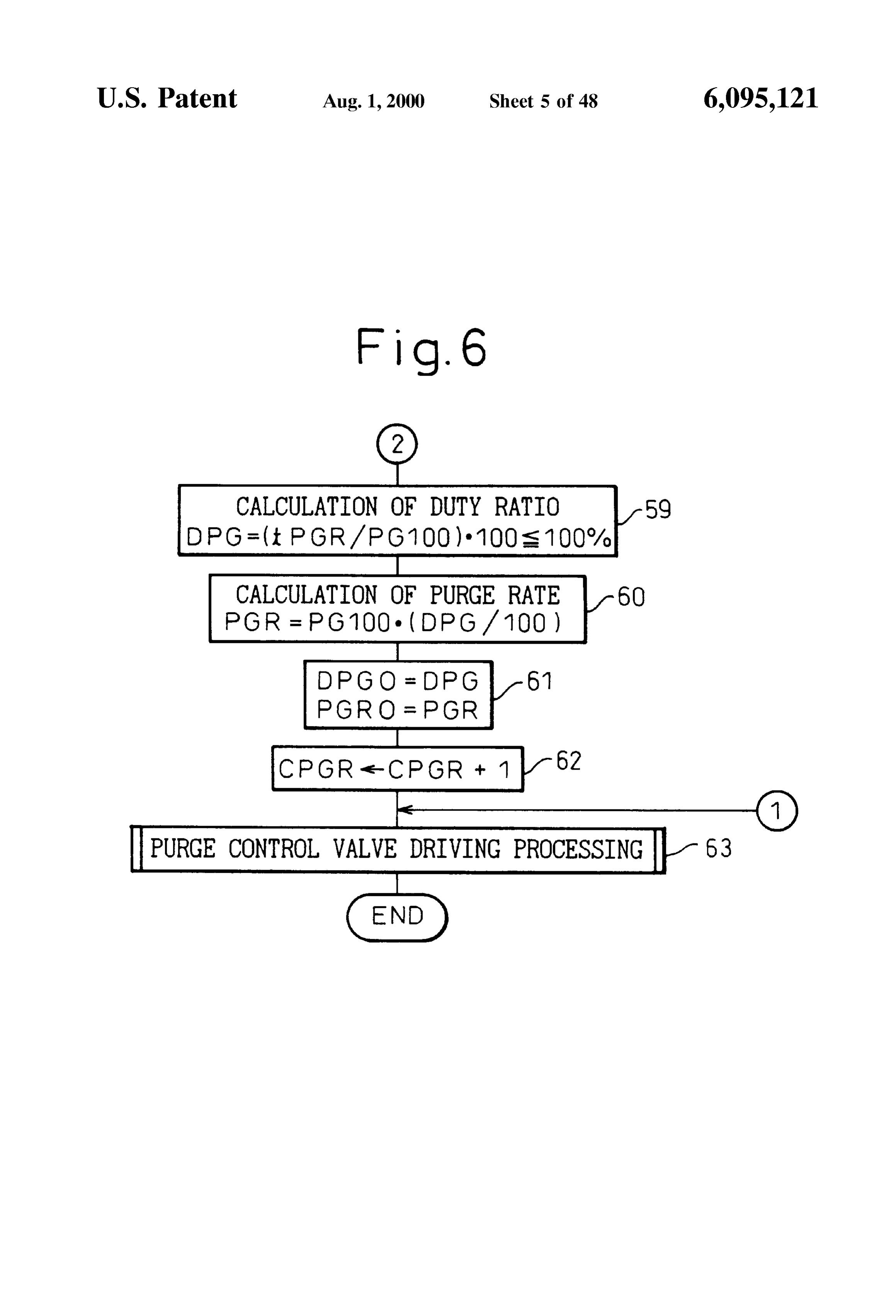
Vapor gradually falls along with the elapse of time and the control valve;
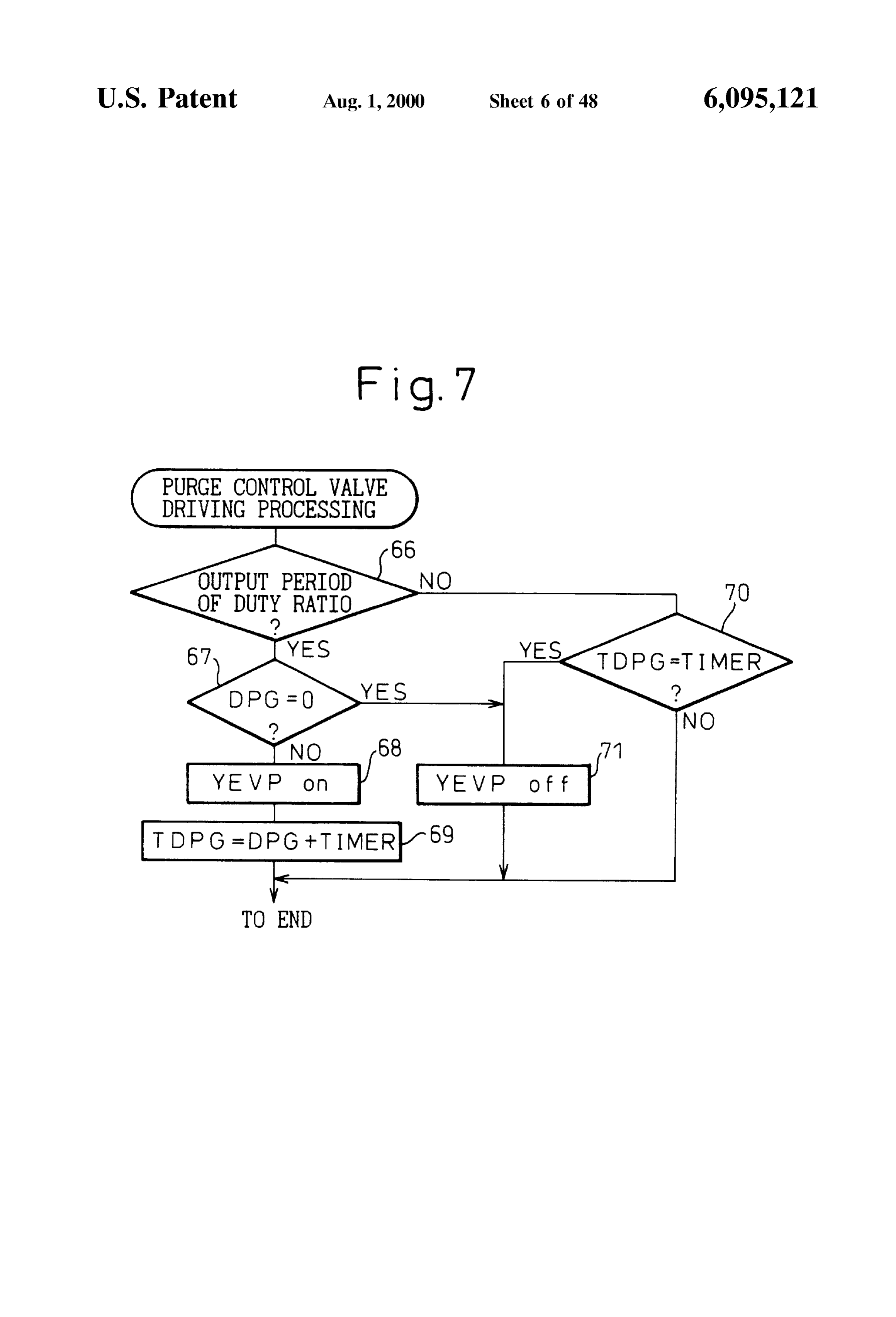
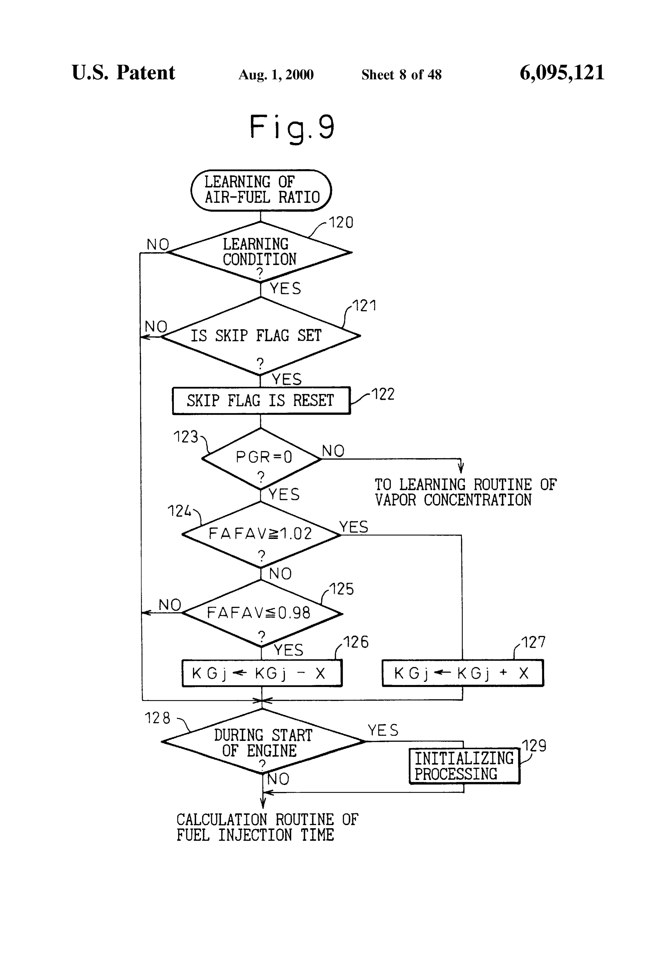
FIG. 8 is a flow chart of calculation of the feedback amount of evaporated fuel is corrected based on this pre dicted concentration of vapor So that fluctuation of the correction coefficient FAF:
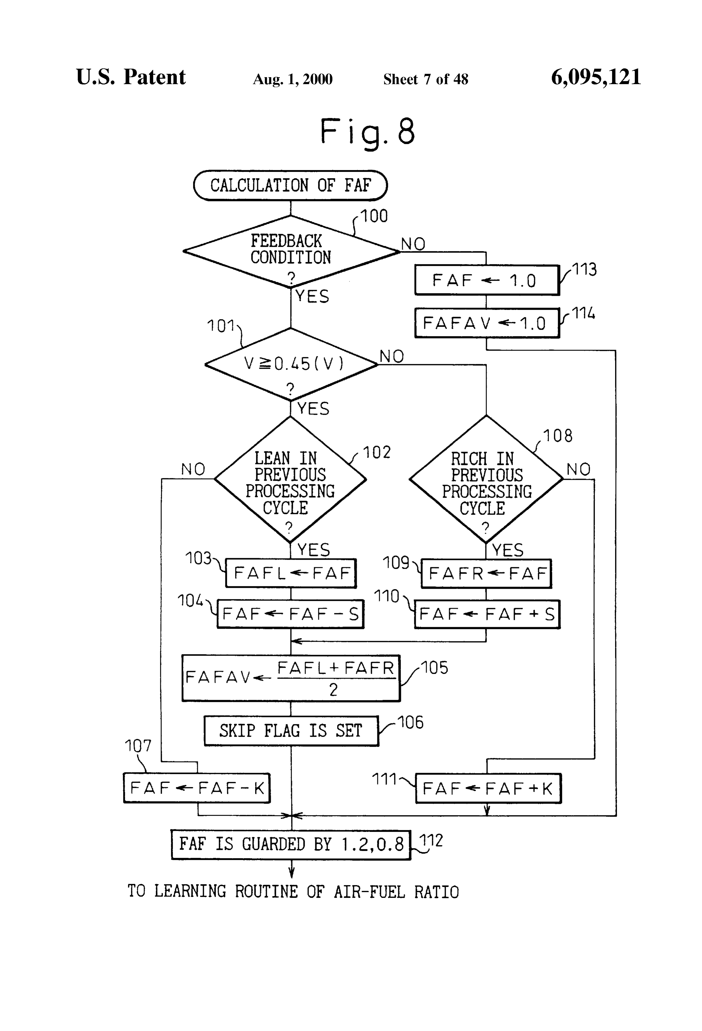
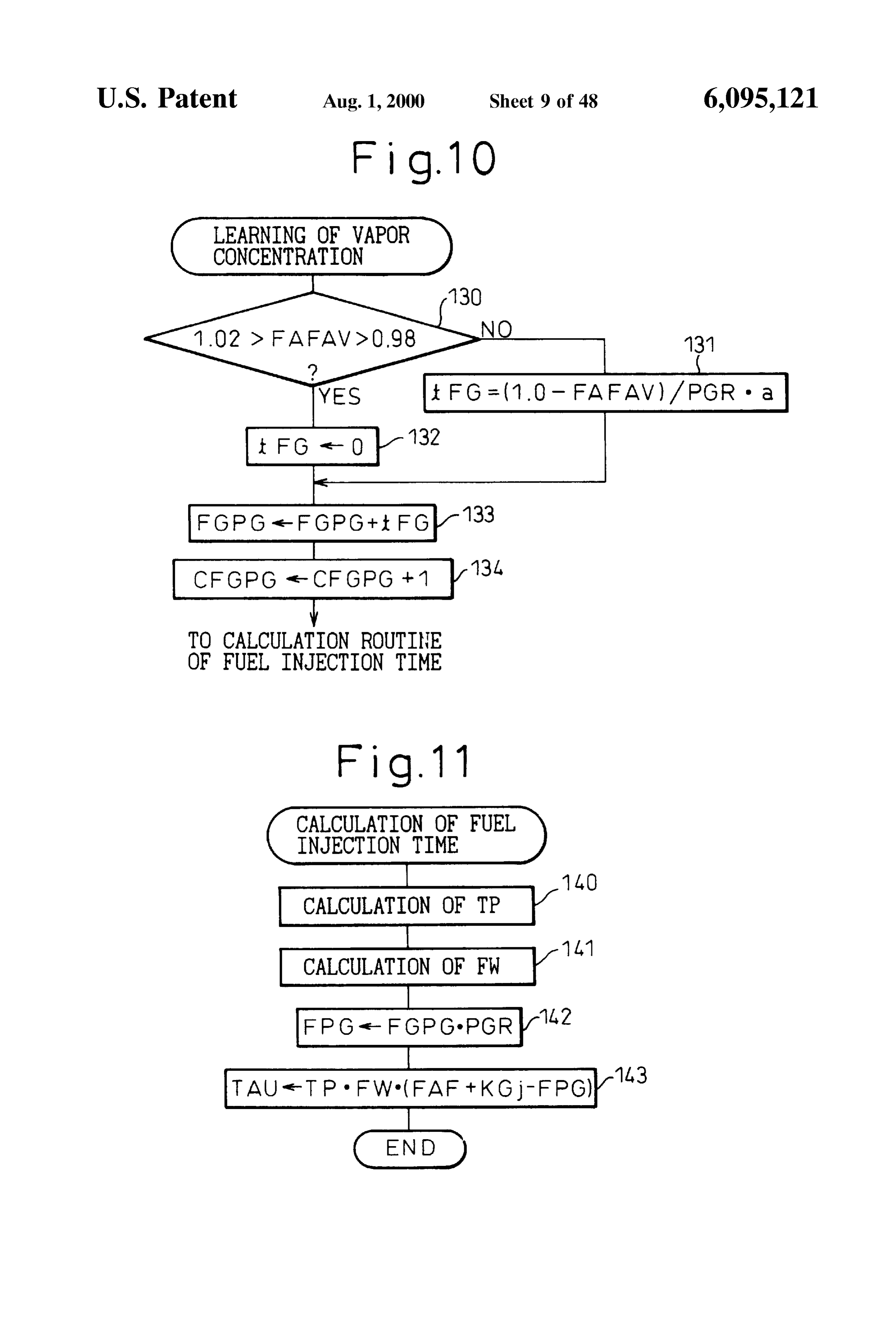
air-fuel ratio is Suppressed. 50 FIG. 9 is a flow chart of learning of the air-fuel ratio; When for example the temperature of the fuel is high, FIG. 10 is a flow chart of learning of the concentration of however, a large amount of evaporated fuel is absorbed in Vapor, the canister when the purge is temporarily Stopped and FIG. 11 is a flow chart of calculation of a fuel injection therefore the amount of absorbed evaporated fuel of the 55 time;
canister increases. In the above internal combustion engine, FIG. 12 is a view of changes in the concentration of vapor however, even in this case, the amount of absorbed evapo FGPG;
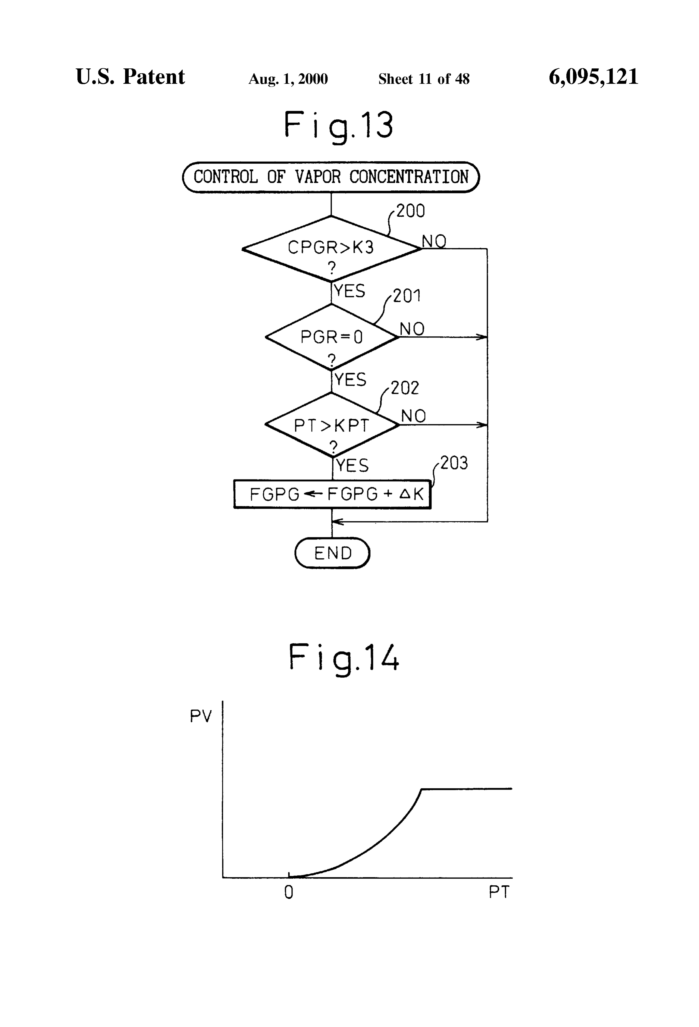
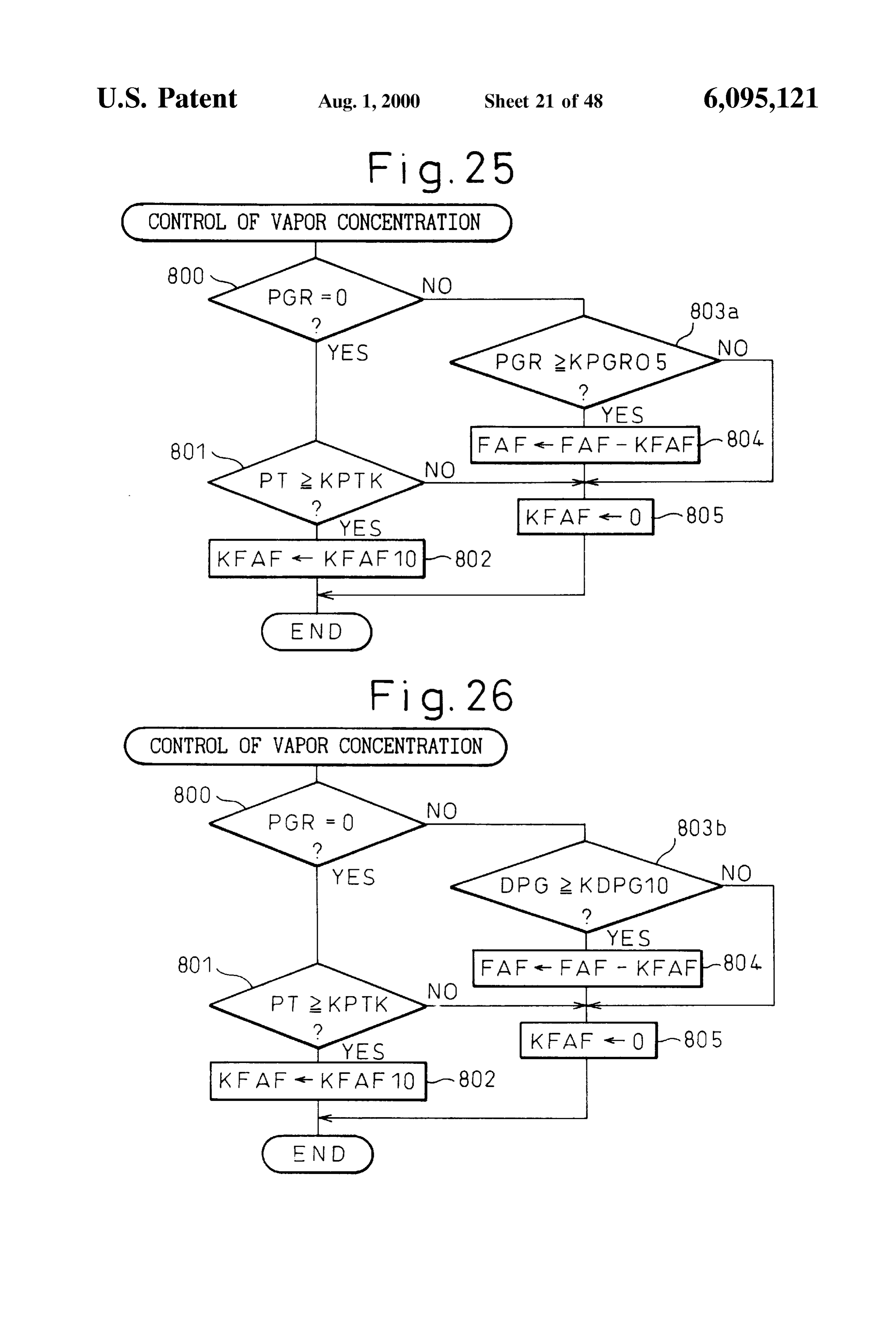
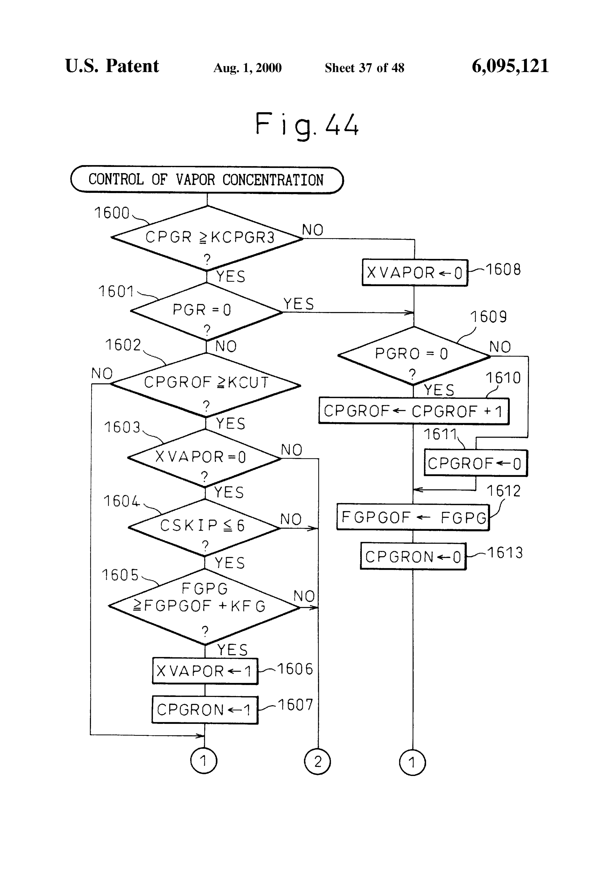
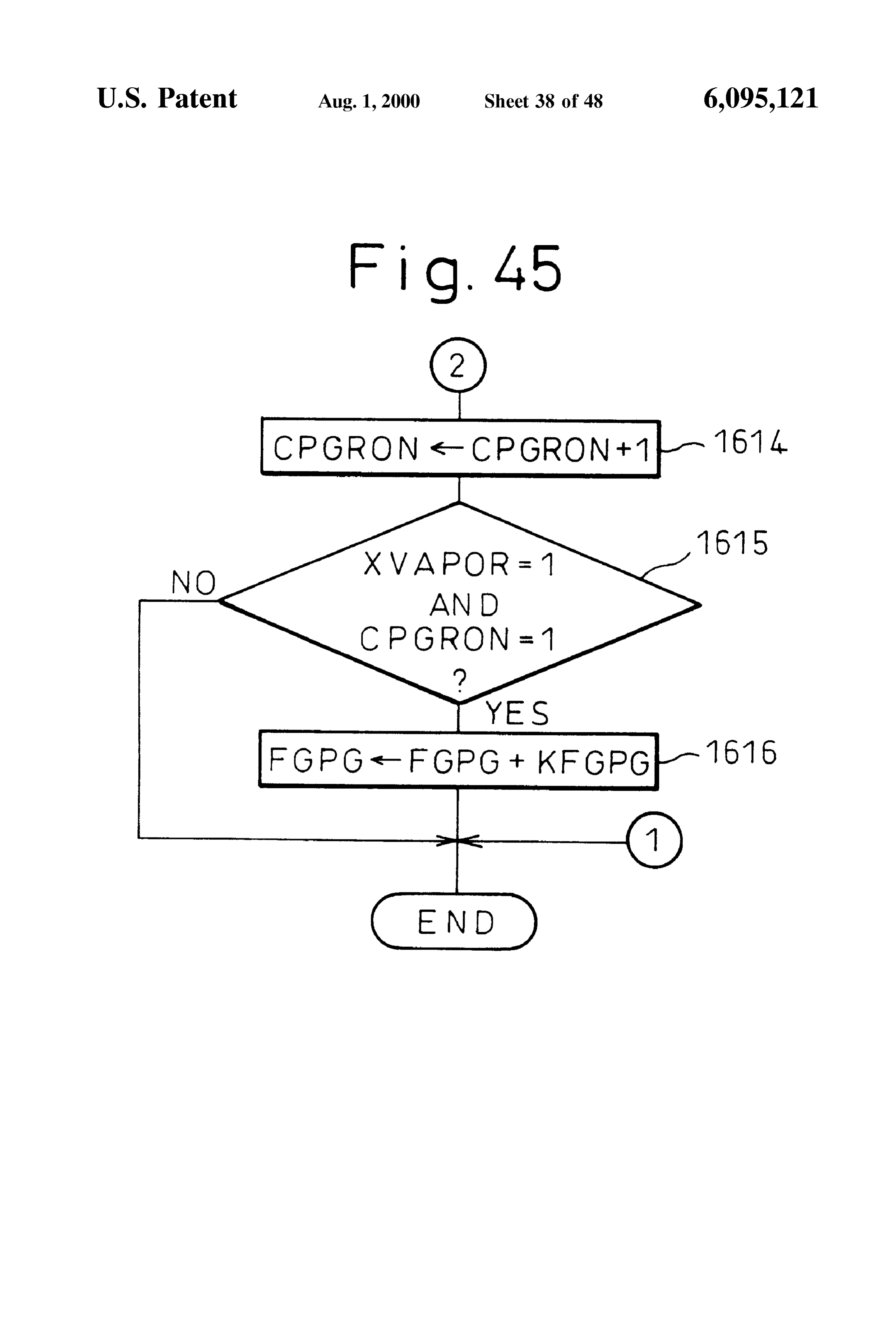
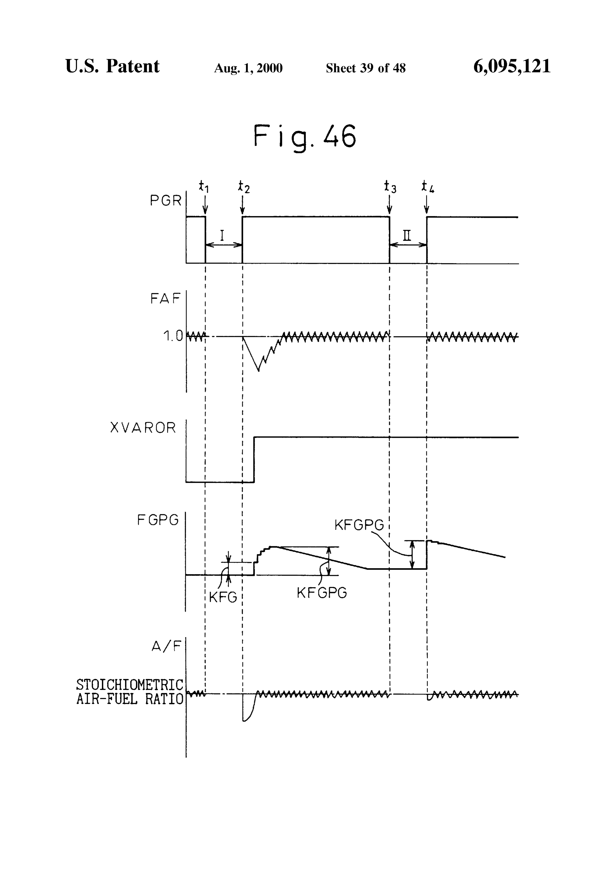
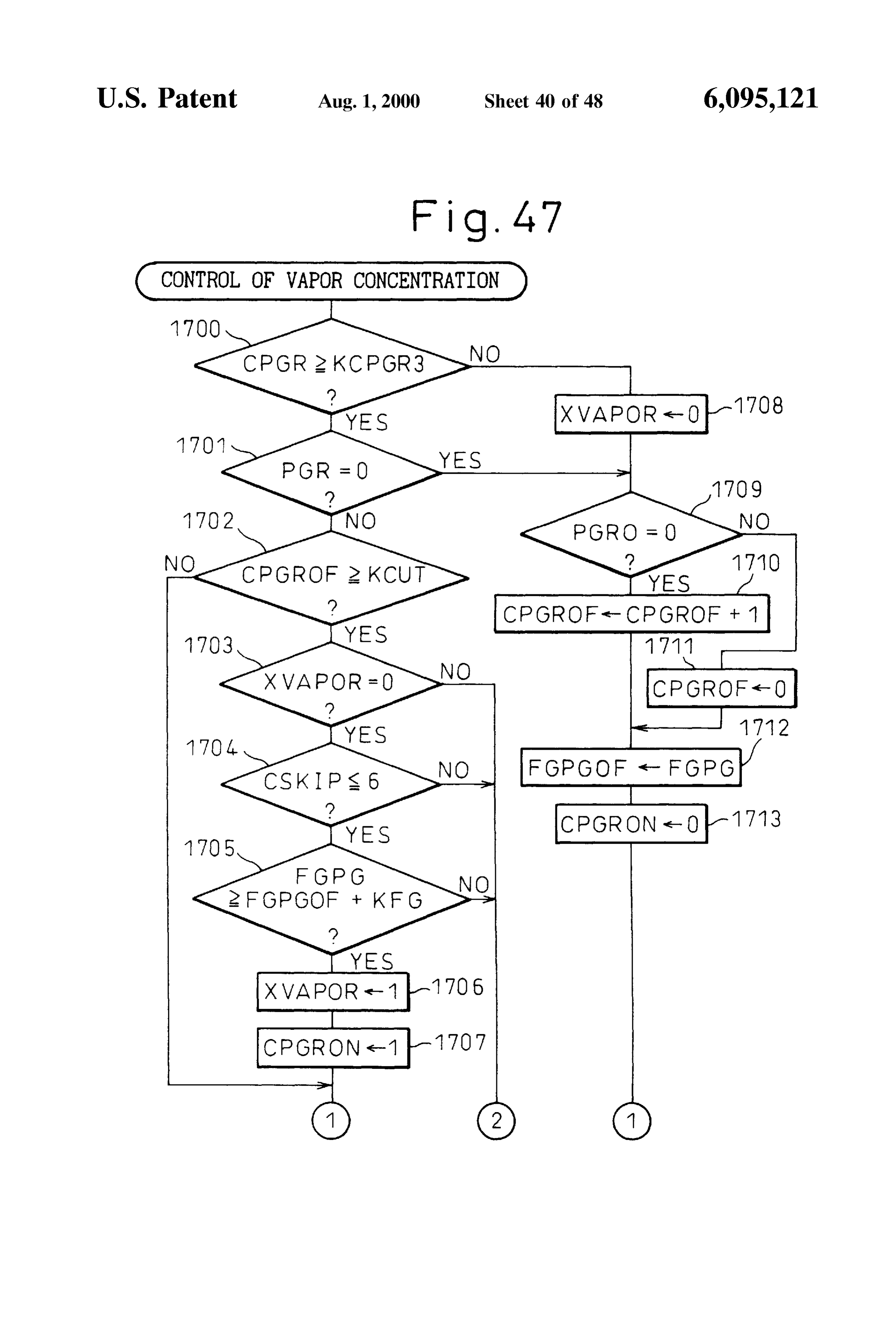
rated fuel of the canister is considered to gradually fall. FIG. 13 is a flow chart of the control of the concentration Since the predicted value of the concentration of vapor also of vapor in a first embodiment;
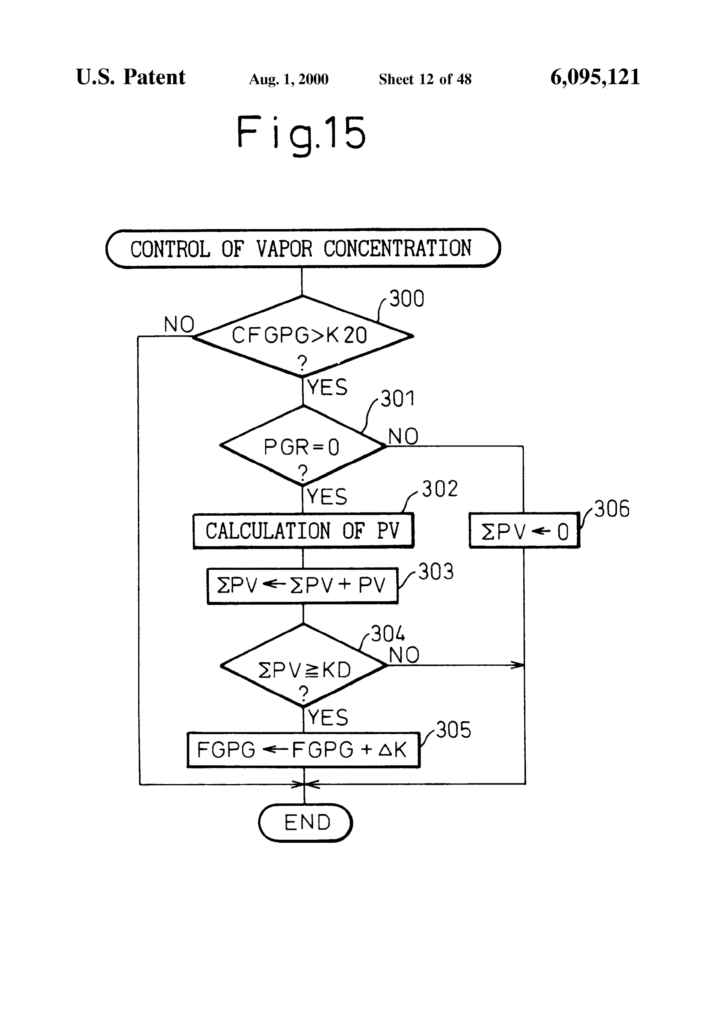
is made to gradually fall, when the purge is restarted, the 60 FIG. 14 is a view of the relationship between the pressure predicted value of the concentration of vapor deviates con PT in a fuel vapor chamber and an amount of evaporated fuel siderably from the actual concentration of vapor and there PV;
fore the problem arises of a considerable fluctuation in the FIG. 15 is a flow chart of the control of the concentration air-fuel ratio.
of vapor in a Second embodiment;
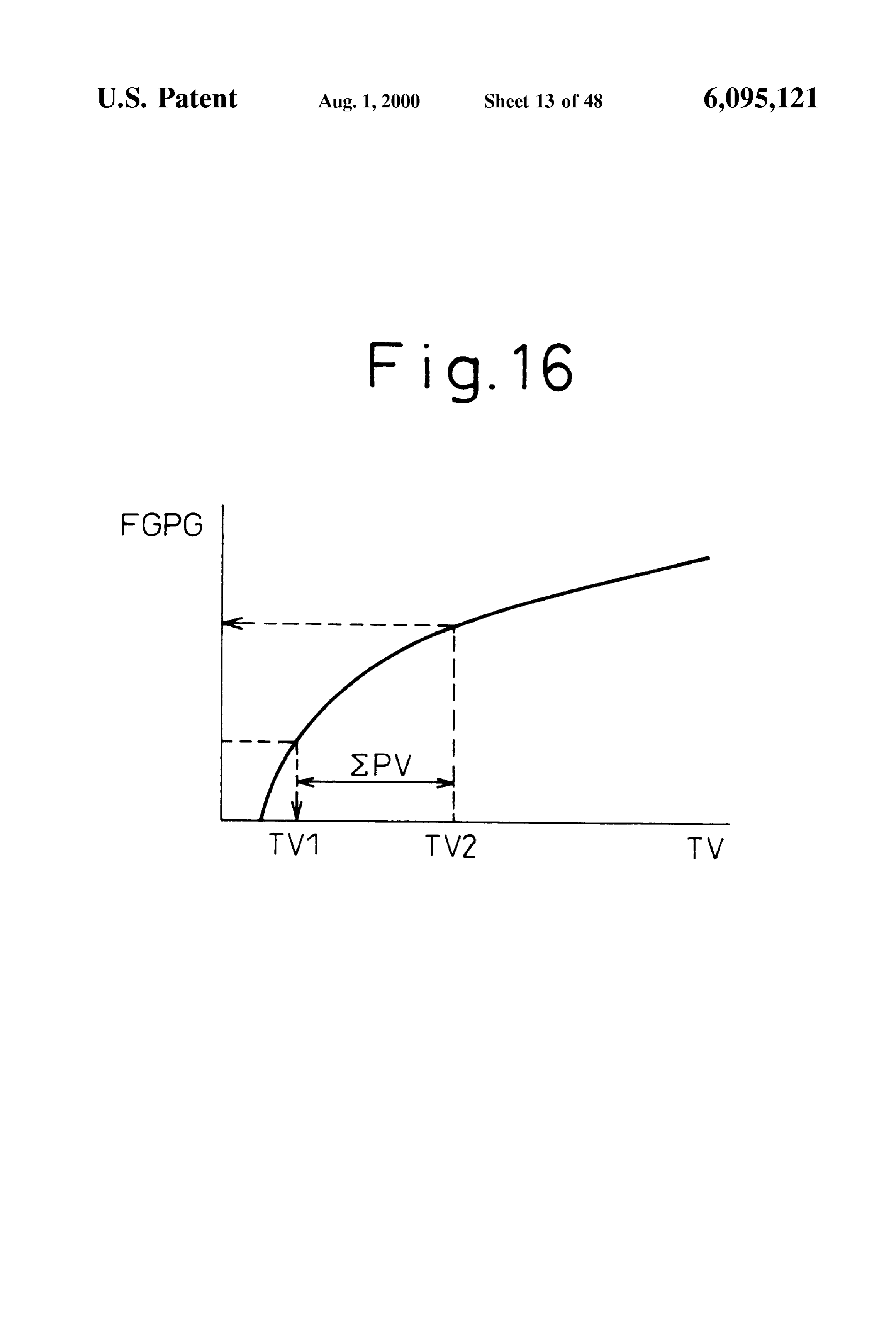
SUMMARY OF THE INVENTION 65 FIG. 16 is a view of the relationship between the con An object of the present invention is to provide an centration of vapor FGPG and the amount of evaporated fuel evaporated fuel treatment device capable of preventing an TV;
Page 51
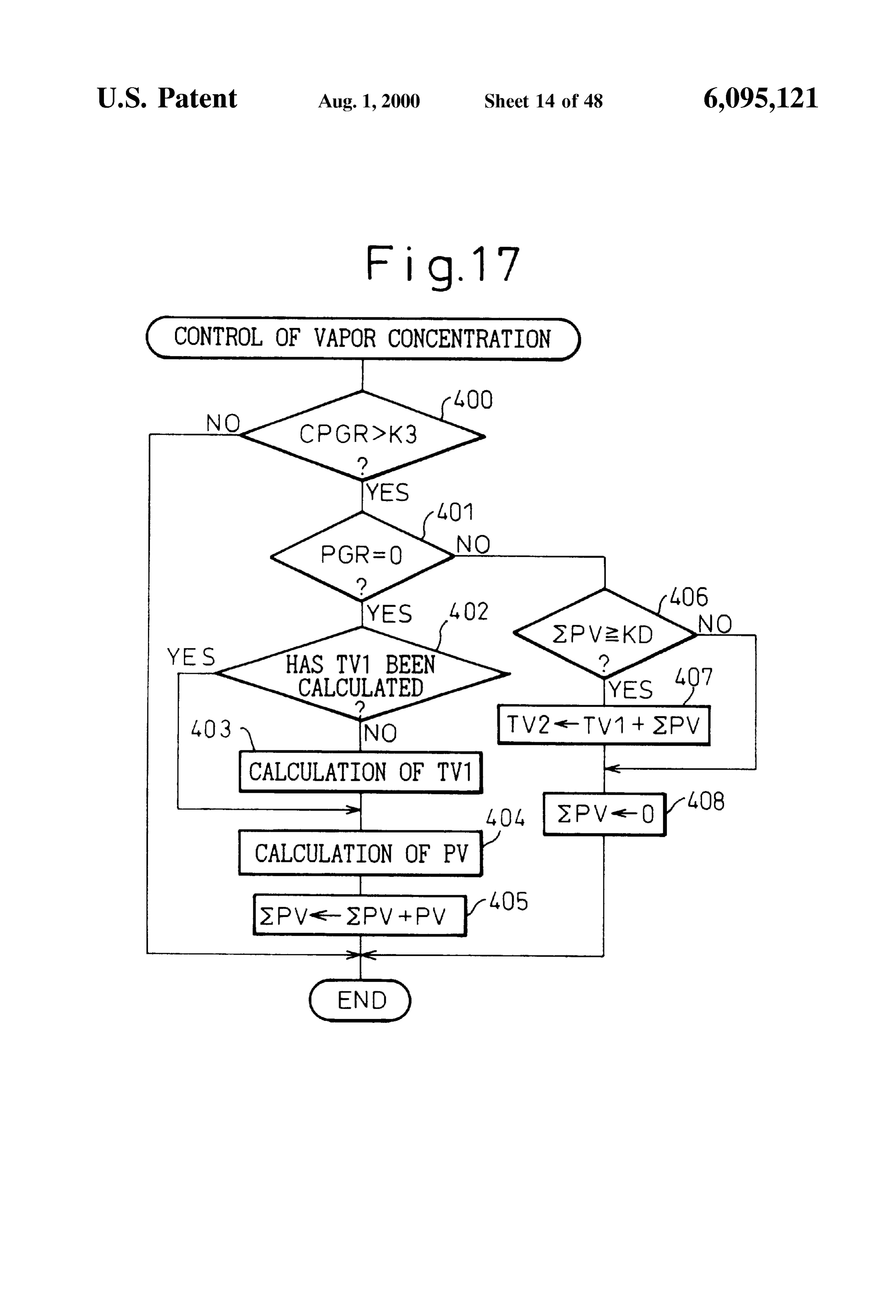
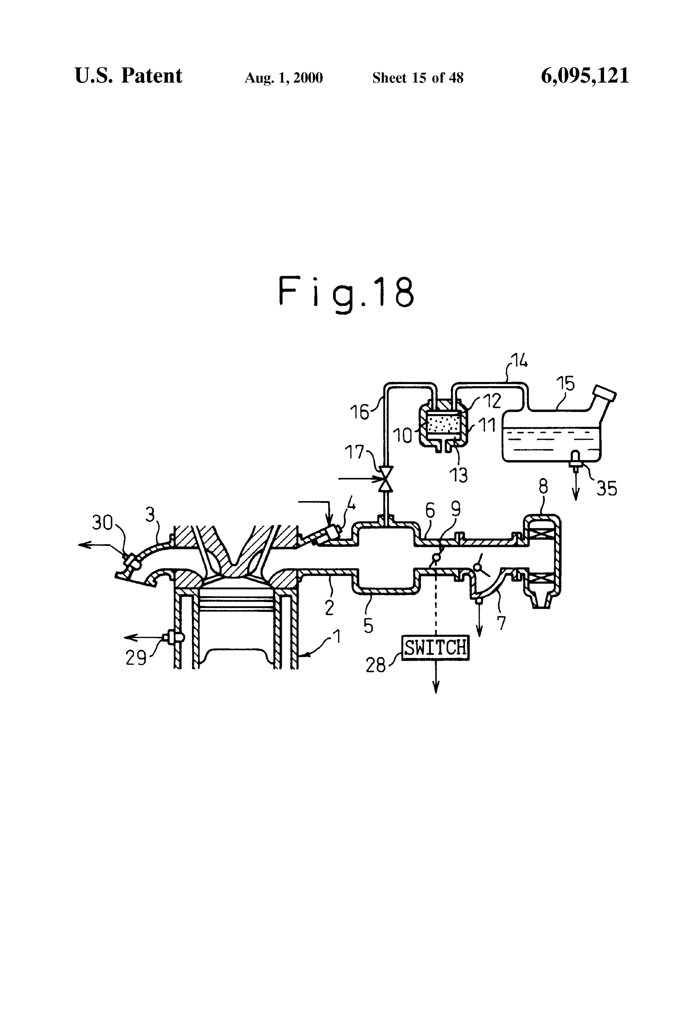
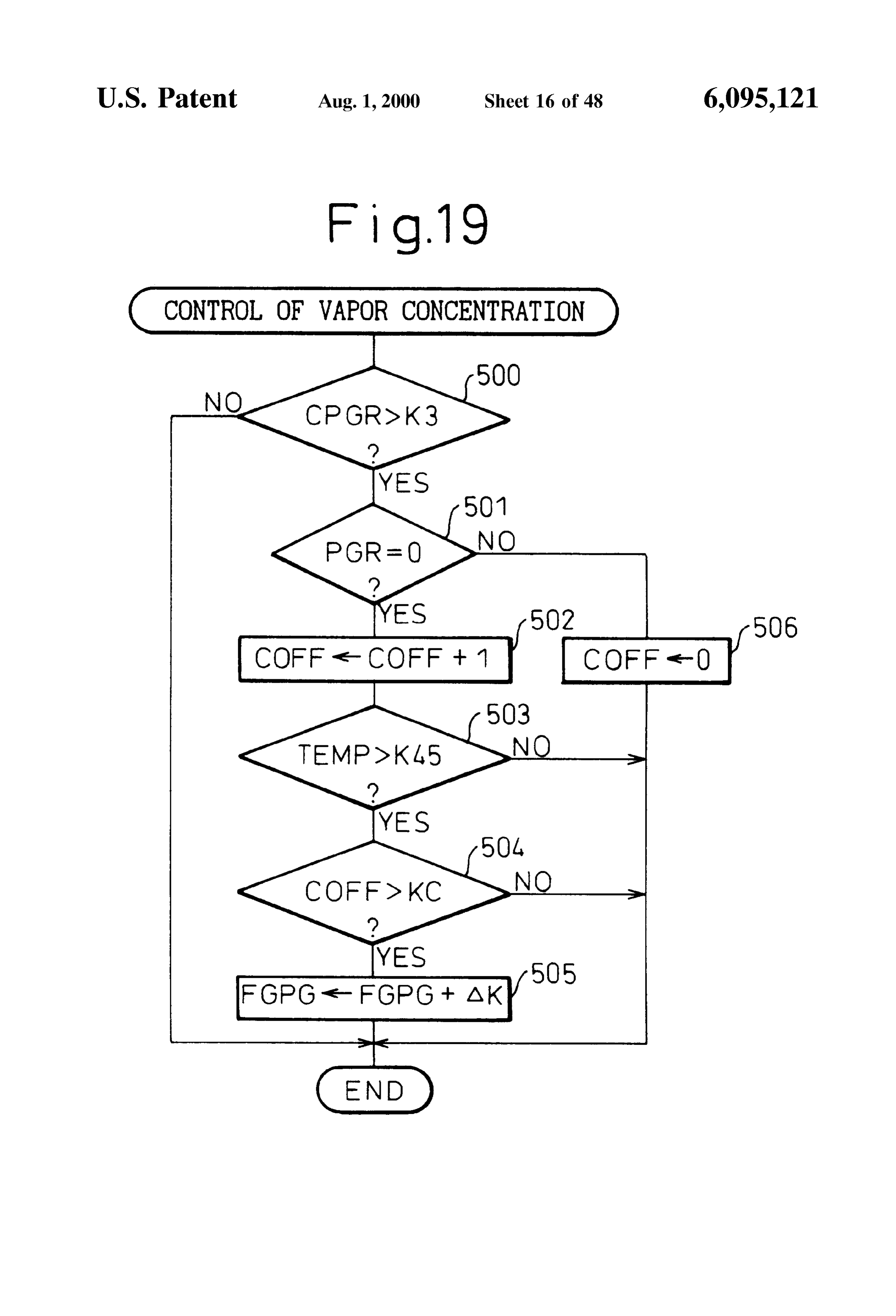
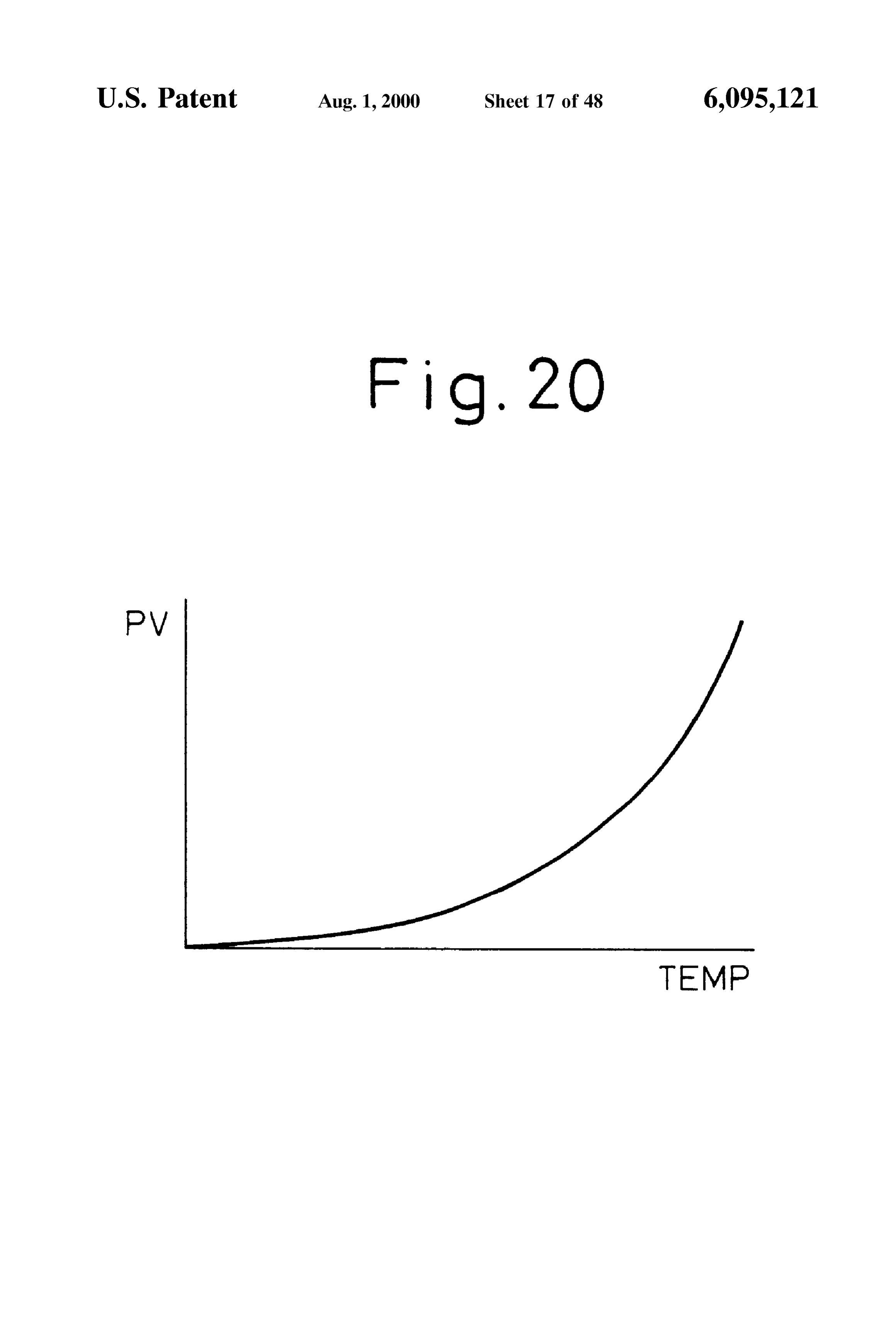
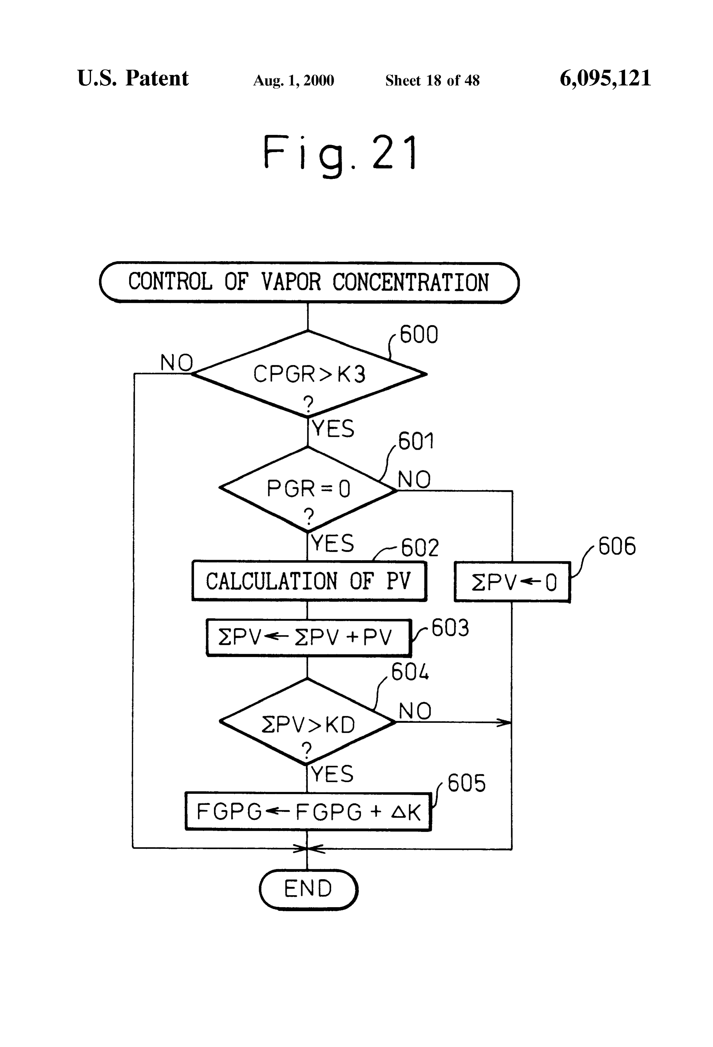
FIG. 17 is a flow chart of the control of the concentration FIGS. 51 and 52 are flow charts of the control of the of vapor in a third embodiment; concentration of vapor in a 18th embodiment; FIG. 18 is an overview of an internal combustion engine; FIG. 53 is a view of the feedback correction coefficient FIG. 19 is a flow chart of control of the concentration of FAF, concentration of vapor FGPG, air-fuel ratio A/F, etc.; Vapor in a fourth embodiment; FIG. 54 is a flow chart of the control of a vapor concen FIG. 20 is a view of the relationship between a fuel tration increase flag XVAPOR; and temperature TEMP in a fuel tank and an amount of evapo FIG. 55 is a flow chart of another embodiment of the rated fuel PV; control of a vapor concentration increase flag XVAPOR. FIG. 21 is a flow chart of the control of the concentration 1O DESCRIPTION OF THE PREFERRED of vapor in a fifth embodiment; EMBODIMENTS
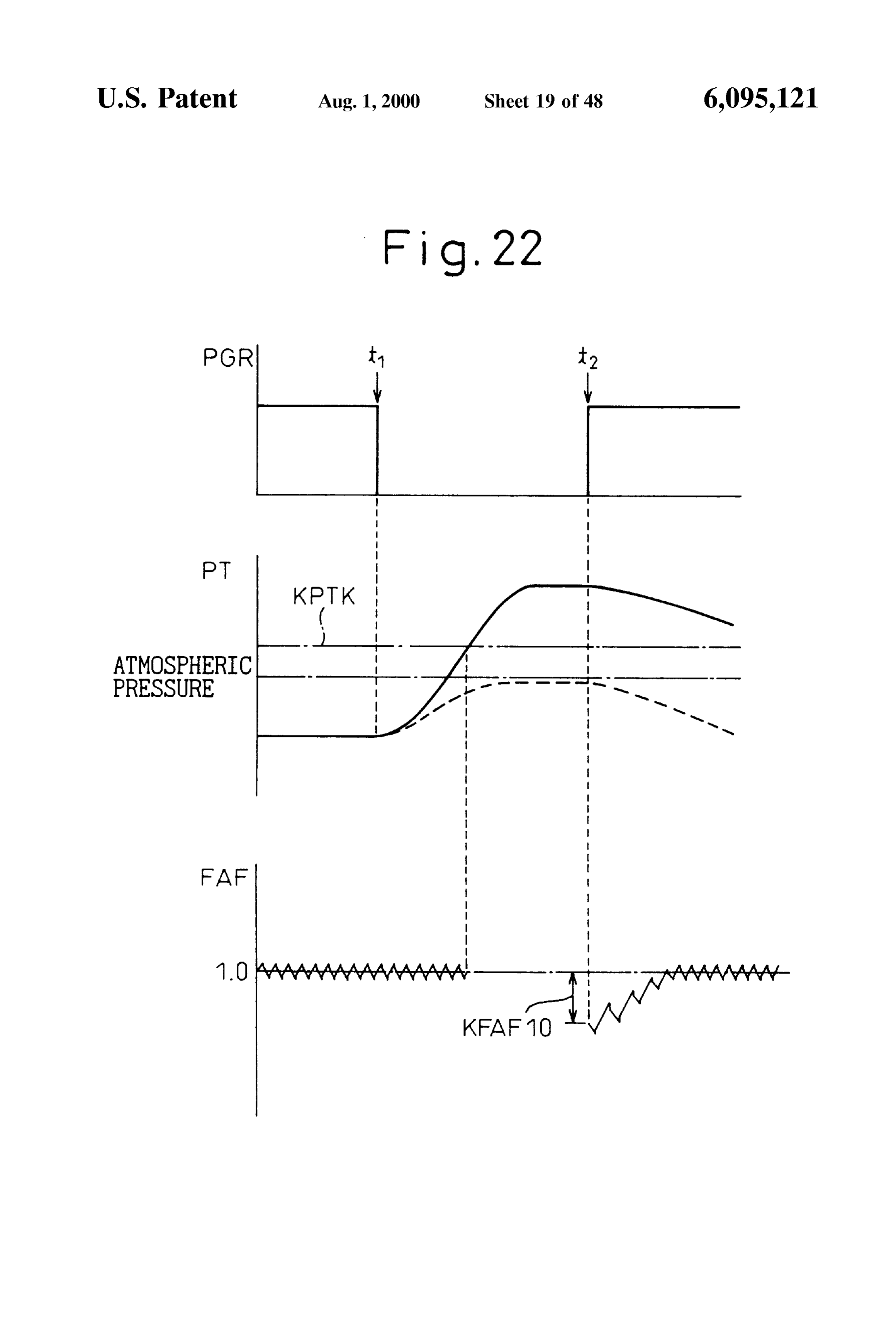
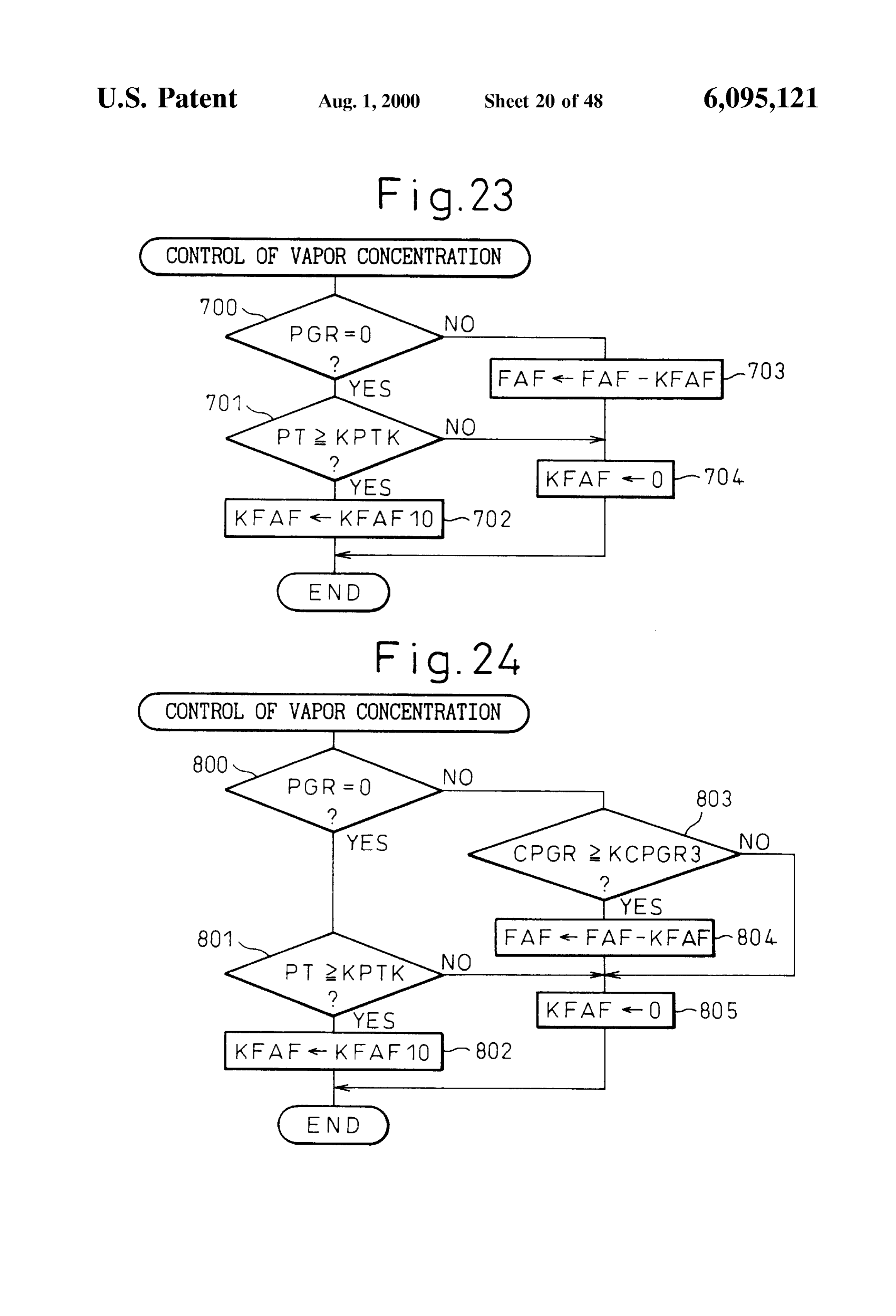
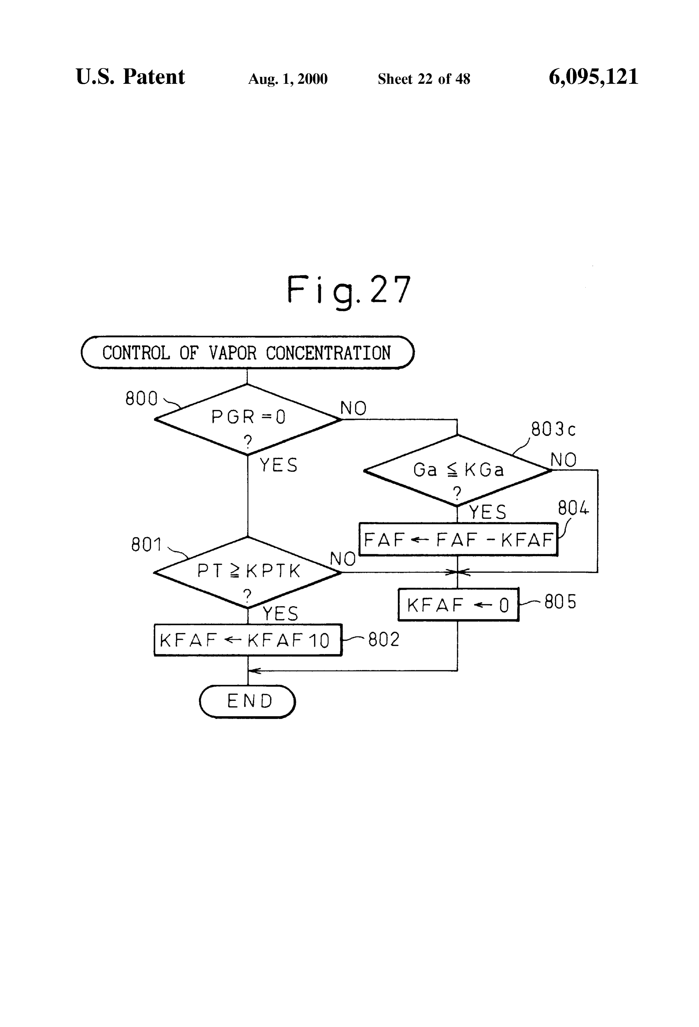
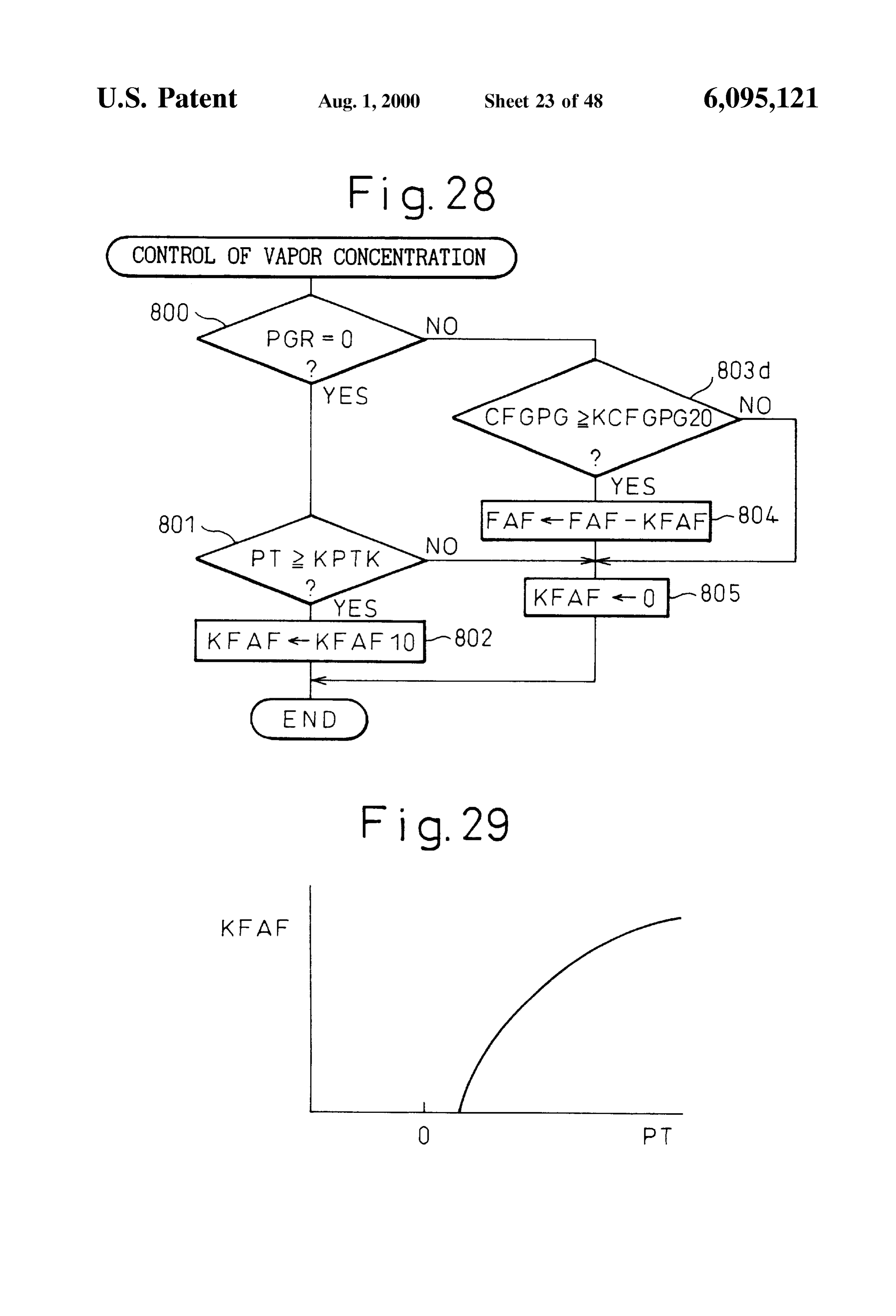
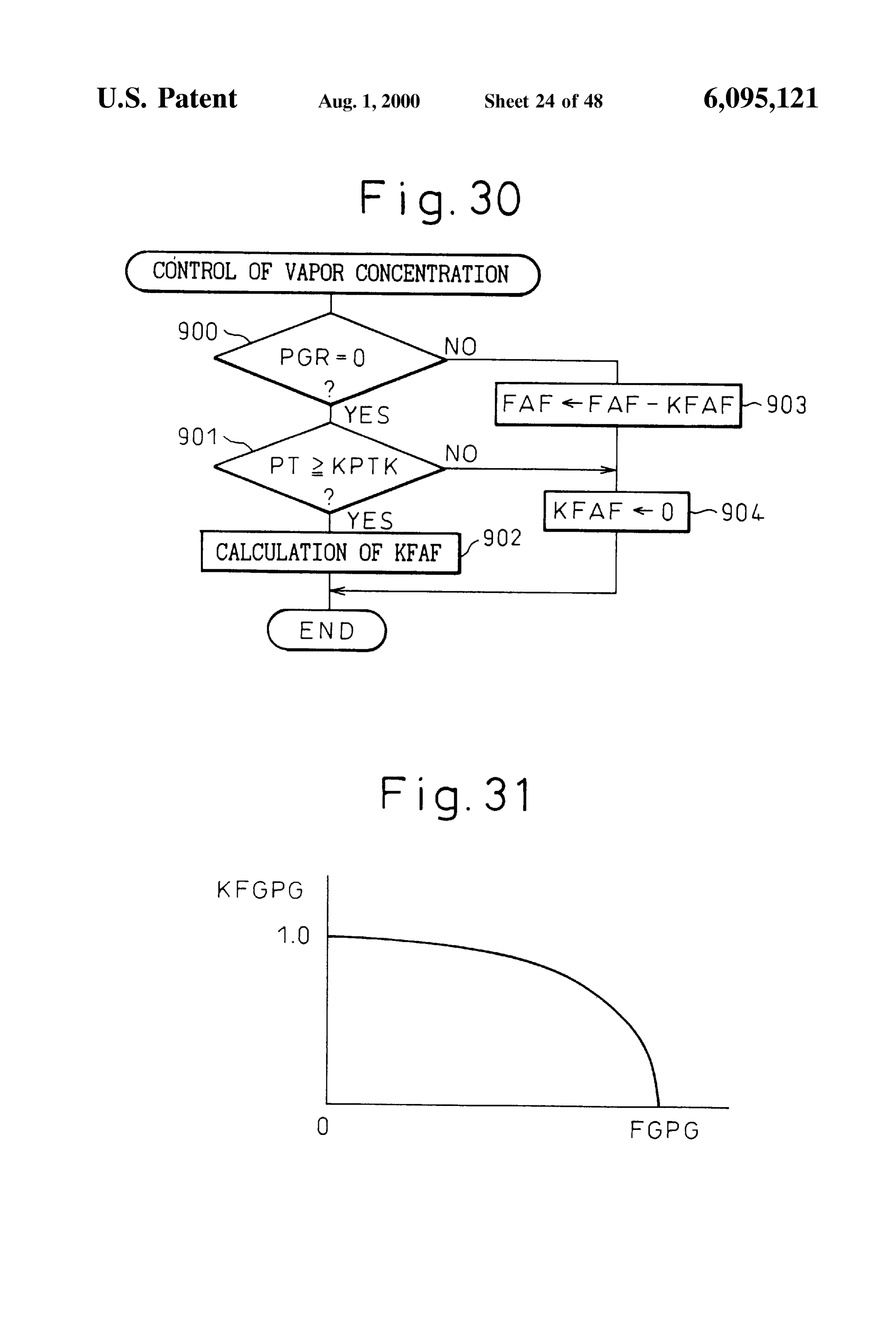
FIG. 22 is a view of changes in the feedback correction coefficient FAF etc.; Referring to FIG. 1, 1 is an engine body, 2 an intake tube, FIG. 23 is a flow chart of the control of the concentration 3 an exhaust manifold, and 4 a fuel injector attached to each 15 of the intake tubes 2. Each intake tube 2 is connected to a of vapor in a sixth embodiment; common Surge tank 5. The Surge tank 5 is connected through FIG. 24 is a flow chart of a seventh embodiment of the an intake duct 6 and an air flow meter 7 to an air cleaner 8. control of the concentration of vapor; In the intake duct 6 is arranged a throttle valve 9. Further, as FIG. 25 is a flow chart of the control of the concentration shown in FIG. 1, the internal combustion engine has dis of vapor showing a modification of a Seventh embodiment; posed in it a canister 11 containing activated carbon 10. The FIG. 26 is a flow chart of the control of the concentration canister 11 has a fuel vapor chamber 12 and an atmospheric of vapor showing a modification of the Seventh embodiment; chamber 13 on the two sides of the activated carbon 10. The FIG. 27 is a flow chart of the control of the concentration fuel vapor chamber 12 on the one hand is connected through of vapor showing a modification of the Seventh embodiment; a conduit 14 to the upper Space of a fuel tank 15 and on the FIG. 28 is a flow chart of the control of the concentration 25 other hand through a conduit 16 to the inside of the Surge of vapor showing a modification of the Seventh embodiment; tank 5. In the conduit 16 is disposed a purge control valve 17 which is controlled by output signals from an electronic
FIG. 29 is a view of the relationship of the pressure PT control unit 20. The fuel vapor which is generated in the fuel inside the fuel vapor chamber and the correction amount tank 15 is sent through the conduit 14 into the canister 11 KFAF: where it is absorbed by the activated carbon 10. When the FIG. 30 is a flow chart of the control of the concentration purge control valve 17 opens, the air is Sent from the of vapor in an eighth embodiment; atmospheric chamber 13 through the activated carbon 10 FIG. 31 is a view of the relationship between the con into the conduit 16. When the air passes through the acti centration of vapor FGPG and the correction coefficient vated carbon 10, the fuel vapor which is absorbed in the KFGPG; 35 activated carbon 10 is released from the activated carbon 10 FIG. 32 is a flow chart of the control of the concentration therefore air containing the evaporated fuel, that is, the fuel of vapor in a ninth embodiment; Vapor, is purged through the conduit 16 to the inside of the FIG. 33 is a flow chart of a 10th embodiment of the Surge tank 5.
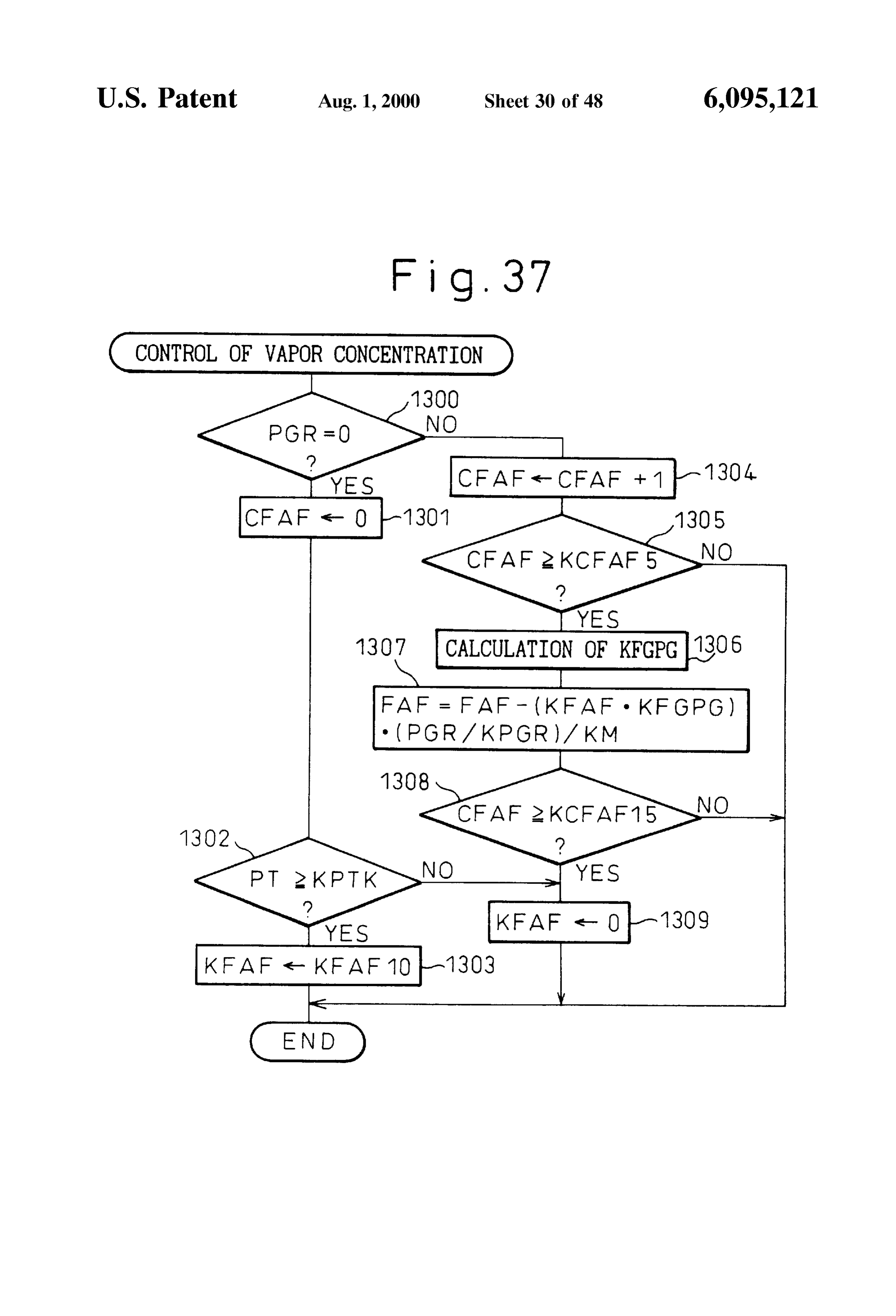
control of the concentration of vapor; The electronic control unit 20 is comprised of a digital FIG. 34 is a view of the changes in the feedback correc 40 computer and is provided with a read only memory (ROM) tion coefficient FAF etc.; 22, a random access memory (RAM) 23, a microprocessor FIG. 35 is a flow chart of the control of the concentration (CPU) 24, an input port 25, and an output port 26 connected of vapor in an 11th embodiment; to each other through a bidirectional bus 21. The air flow meter 7 generates an output voltage proportional to the
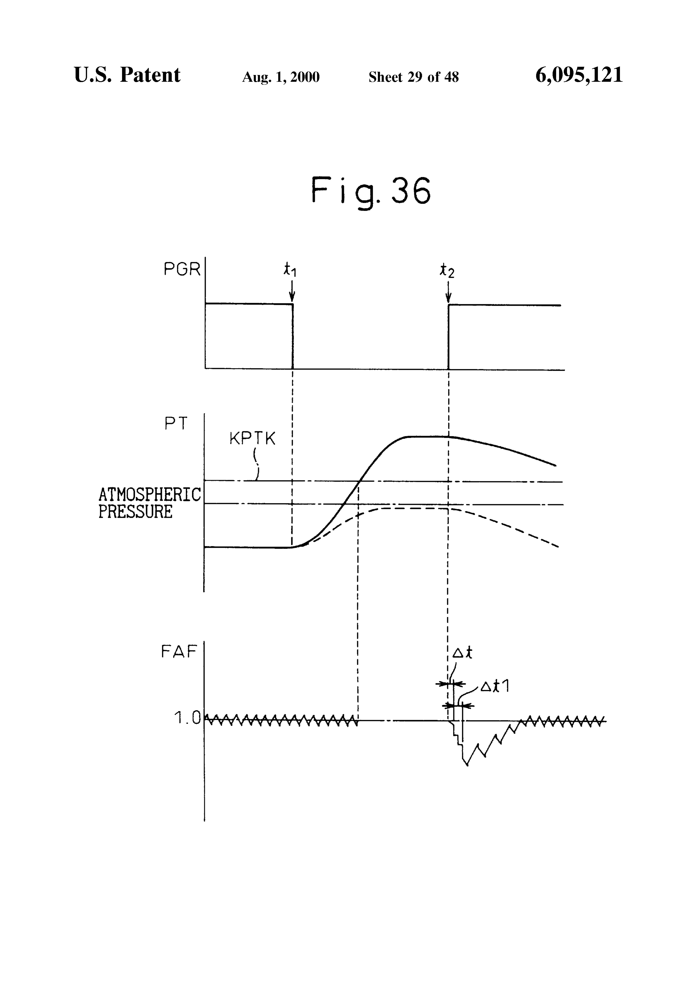
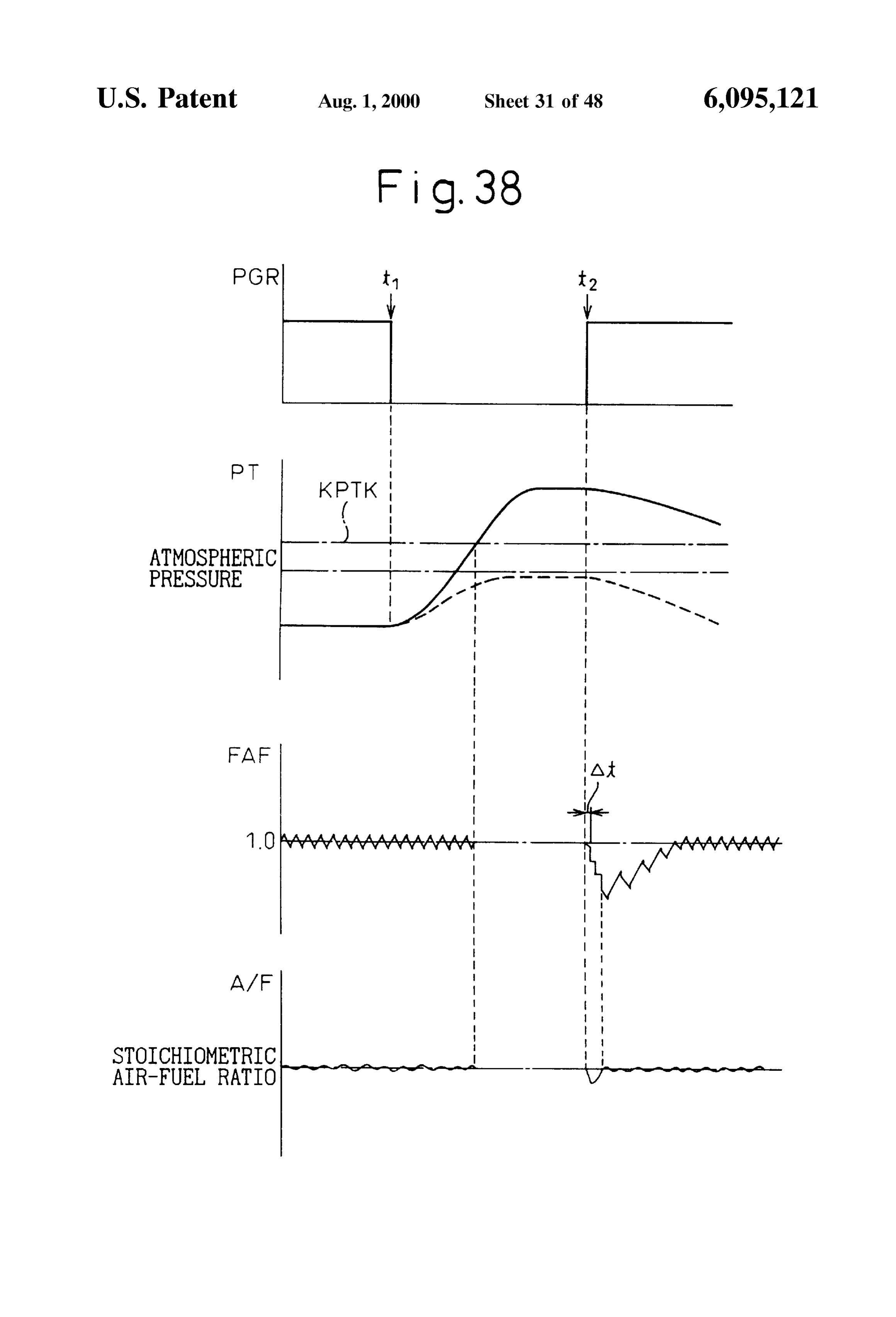
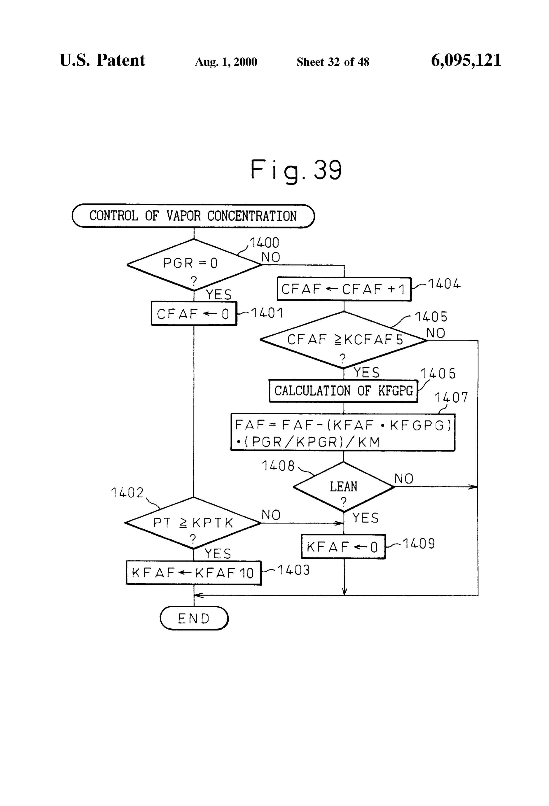
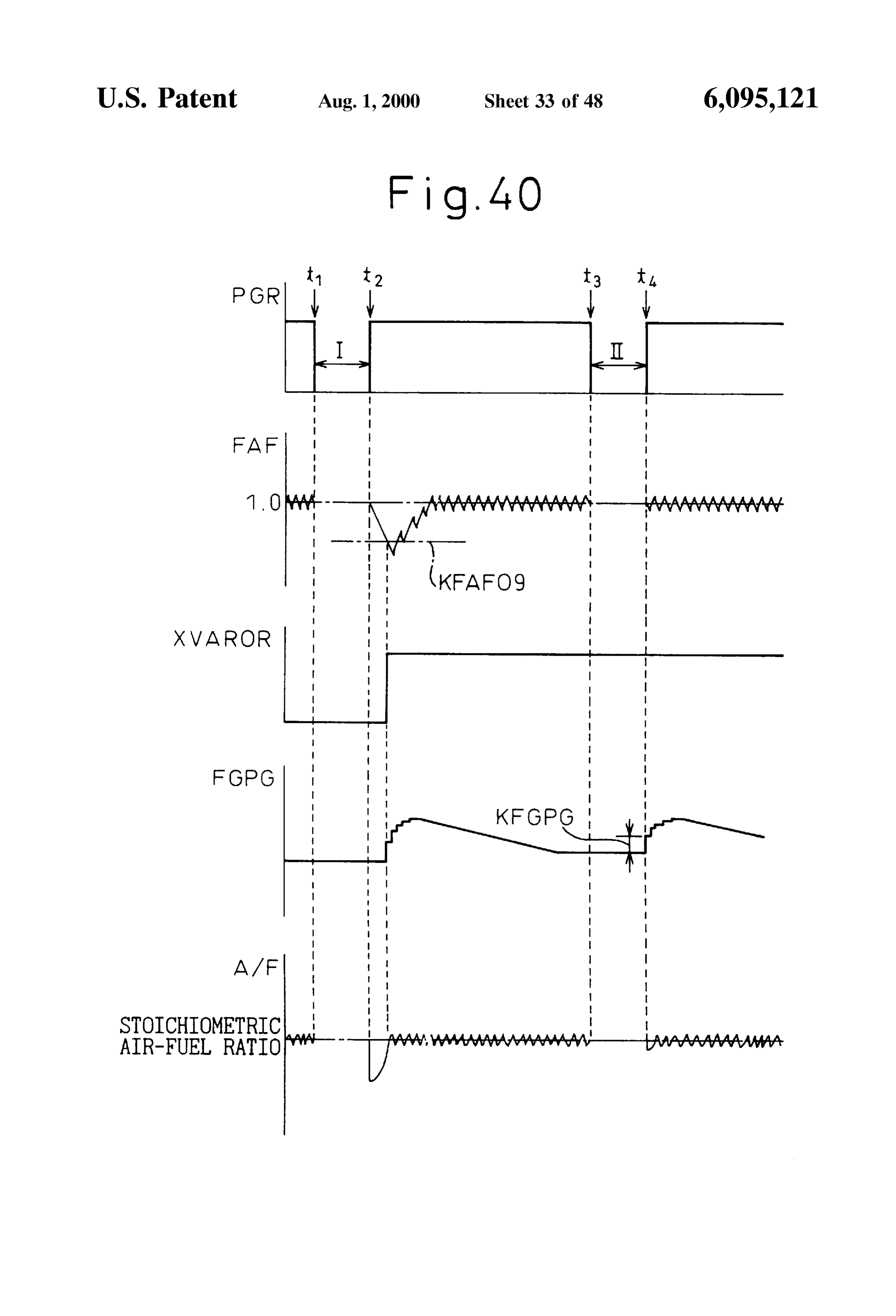
FIG. 36 is a view of the changes in the feedback correc 45 amount of intake air. This output voltage is input through a tion coefficient FAF etc.; corresponding AD converter 27 to the input port 35. The FIG. 37 is a flow chart of the control of the concentration throttle valve 9 has attached to it a throttle Switch 28 which of vapor in a 12th embodiment; is turned on when the throttle valve 9 is at the idling opening. FIG. 38 is a view of the changes in the feedback correc The output signal of the throttle Switch 28 is input to the tion coefficient FAF etc.; 50 input port 25. The engine body 1 has attached to it a water FIG. 39 is a flow chart of the control of the concentration temperature Sensor 29 for generating an output voltage of vapor in a 13th embodiment; proportional to the coolant water temperature of the engine. FIG. 40 is a view of the feedback correction coefficient The output voltage of the water temperature sensor 29 is FAF, concentration of vapor FGPG, air-fuel ratio A/F, etc.; input through the corresponding AD converter 27 to the FIGS. 41 and 42 are flow charts of the control of the 55 input port 25. The exhaust manifold 3 has an air-fuel ratio concentration of vapor in a 14th embodiment; sensor 30 attached to it. The output signal of the air-fuel ratio FIG. 43 is a view of the feedback correction coefficient Sensor 30 is input through the corresponding AD converter FAF, concentration of vapor FGPG, air-fuel ratio A/F, etc.; 27 to the input port 25.
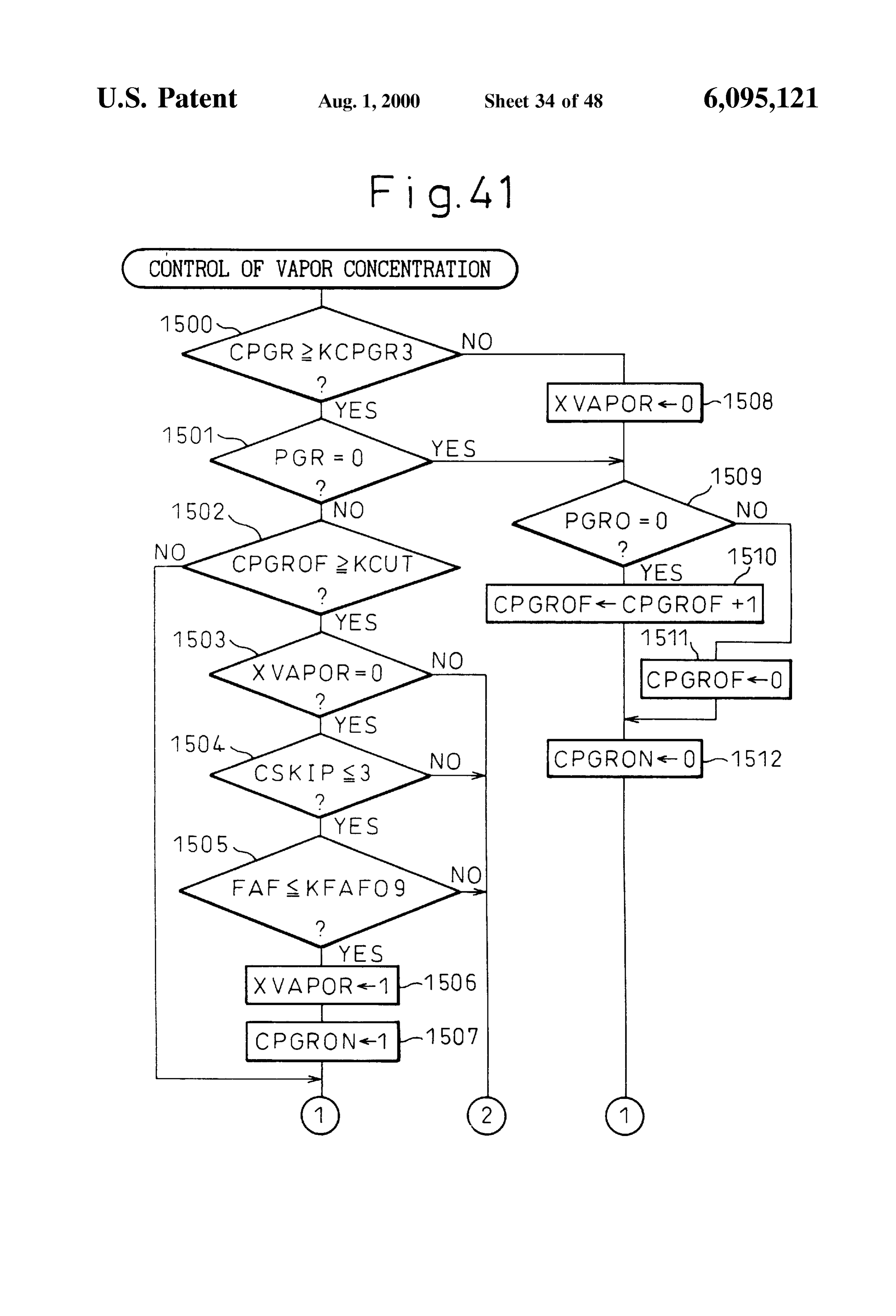
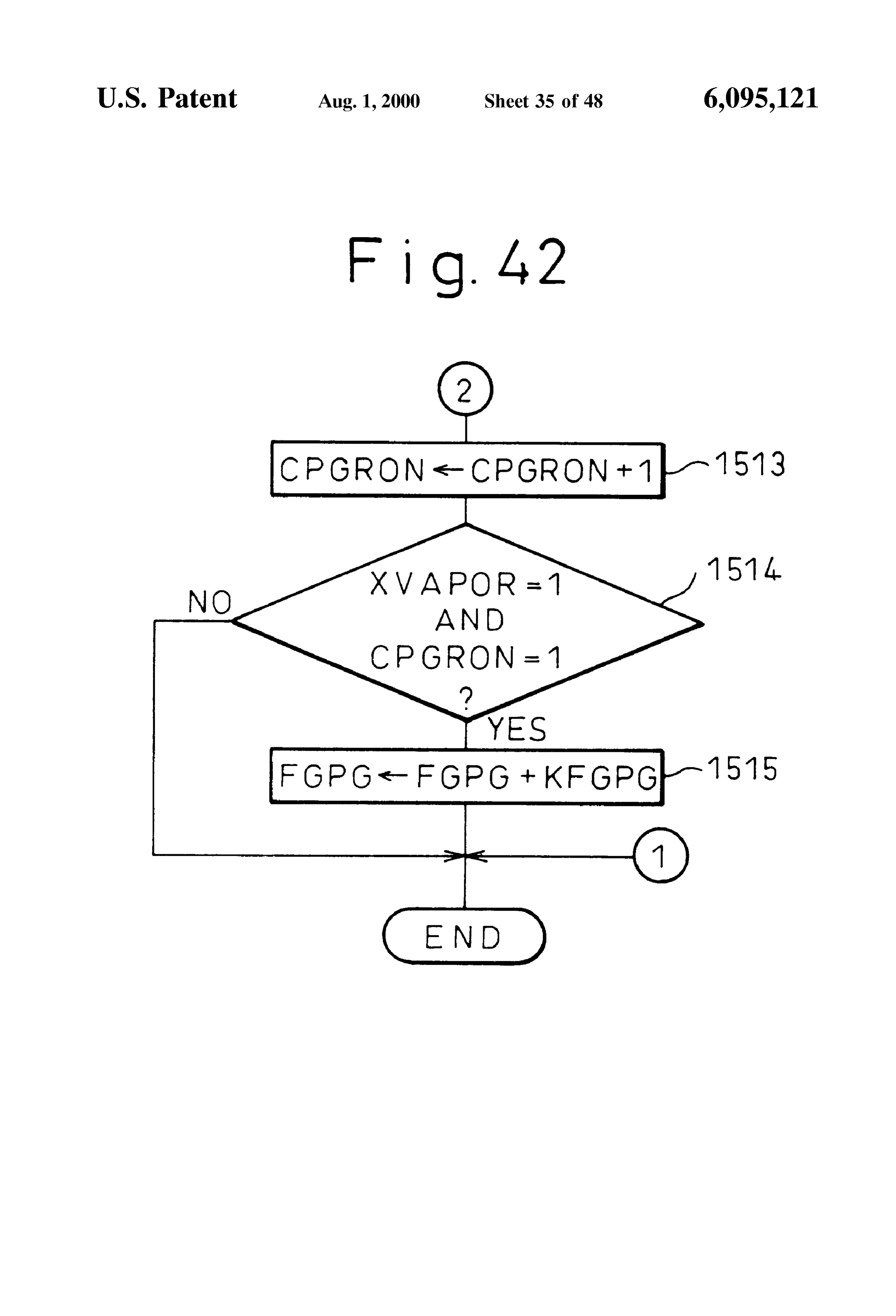
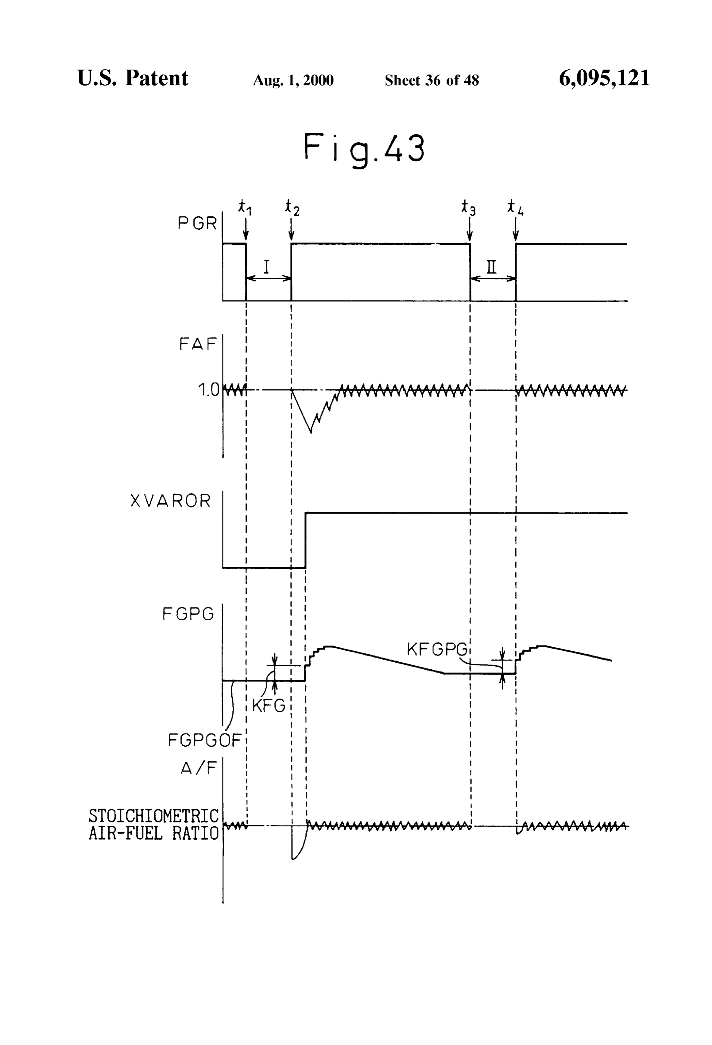
FIGS. 44 and 45 are flow charts of the control of the 60 Further, the fuel vapor chamber 12 is connected through concentration of vapor in a 15th embodiment; a conduit 31 to a pressure Sensor 32. The preSSure Sensor 32 FIG. 46 is a view of the feedback correction coefficient detects the pressure inside the fuel vapor chamber 12. The preSSure Sensor 32 generates an output Voltage proportional
FAF, concentration of vapor FGPG, air-fuel ratio A/F, etc.; to the preSSure in the fuel vapor chamber 12, that is, the FIGS. 47 and 48 are flow charts of the control of the preSSure of the upper space of the fuel tank 15 or the conduit concentration of vapor in a 16th embodiment; 65 16 from the upper space of the fuel tank 15 to the purge FIGS. 49 and 50 are flow charts of the control of the control valve 17. This output voltage is input through an AD concentration of vapor in a 17th embodiment; converter 27 to the input port 25. Further, the input port 25
Page 52
S 6 has connected to it a crank angle Sensor 33 generating an output voltage V of the O sensor 30 becomes lower than the output pulse every time the crankshaft rotates by for reference Voltage, that is, when the air-fuel ratio becomes example 30 degrees. In the CPU 24, the engine speed is lean, the feedback control coefficient FAF is rapidly calculated based on this output pulse. On the other hand, the increased by the Skip amount S and then gradually increased output port 26 is connected through the corresponding drive by the integration constant K. circuit 34 to the fuel injectors 4 and the purge control valve That is, when the air-fuel ratio becomes rich, the feedback 17. control coefficient FAF is reduced, so the amount of fuel In the internal combustion engine shown in FIG. 1, the injection is reduced, while when the air-fuel ratio becomes lean, the feedback control coefficient FAF is increased and fuel injection time TAU is basically calculated based on the the amount of fuel injection is increased. Therefore, the following equation: air-fuel ratio is maintained at the Stoichiometric air-fuel ratio. As shown in FIG. 2, at this time, the feedback control coefficient FAF fluctuates about a reference value, that is,
where, the coefficients show the following: Further, in FIG. 2, FAFL shows the value of the feedback TP: basic fuel injection time 15
FW: correction coefficient control coefficient FAF when the air-fuel ratio changes from FAF: feedback correction coefficient lean to rich, while FAFR shows the value of the feedback KG: learning coefficient of air-fuel ratio control coefficient FAF when the air-fuel ratio changes from FPG: purge air-fuel ratio correction coefficient rich to lean. In the embodiment of the present invention, as (hereinafter referred to as the purge A/F correction the average of the fluctuation of the feedback control coef coefficient) ficient FAF (hereinafter referred to simply as the average The basic fuel injection time TP is the experimentally value), the average value between FAFL and FAFR is used. found injection time required for making the air-fuel ratio FIG. 3 Summarizes the purge operation. Note that in FIG. the target air-fuel ratio. The basic fuel injection time TP is 3, PGR shows the purge rate of the fuel vapor. As shown in stored in advance in the ROM 22 as a function of the engine 25 FIG.3, in the embodiment of the present invention, when the load QIN (intake air amount Q/engine speed N) and the purge action is Started for the first time after the Start of engine operation, the purge rate PGR is gradually increased engine Speed N.
The correction coefficient FW expresses the engine war from for zero. When the purge rate PGR reaches a certain value, example, 6 percent, the purge rate PGR is maintained at mup increase coefficient and the acceleration increase coef the target purge rate.
ficient all together. When no upward correction is needed, Next, for example, in the case where the Supply of fuel is FW is made 1.0.
The feedback correction coefficient FAF is set to control Stopped at the time of a deceleration operation, the purge rate the air-fuel ratio to the target air-fuel ratio based on the restarted PGR is temporarily made Zero. Next, the purge operation is output signal of the air-fuel ratio sensor 30. by the purge rate PGR immediately before the The purge A/F correction coefficient FPG is made 0 in the 35 purge operation was stopped.
interval from when the engine Started operating to when the learning the concentrationwill
Next, an explanation be made of the method of of the fuel Vapor referring to FIG.
purge is started. When the purge operation is Started, it 4.
becomes larger the higher the concentration of the fuel The learning of the concentration of the fuel vapor starts Vapor. Note that when the purge operation is temporarily
Stopped during the engine operation, FPG is made 0 while 40 with the accurate determination of the vapor concentration the purge operation is Stopped. per unit purge rate. The vapor concentration per unit purge AS explained above, however, the feedback control coef rate is shownFPG by FGPG in FIG. 4. The purge A/F correction ficient FAF is for controlling the air-fuel ratio to the target coefficient
PGR with FGPG.
is obtained by multiplying the purge rate air-fuel ratio based on the output Signal of the air-fuel ratio The vapor concentration per unit purge rate FGPG is Sensor 30. In this case, as the target air-fuel ratio, any air-fuel 45 calculated based on the following formula every time the ratio may be used, but in the embodiment shown in FIG. 1, the target air-fuel ratio is made the Stoichiometric air-fuel feedback correction coefficient FAF skips (S in FIG. 2): ratio, therefore the explanation will be made of the case of making the target air-fuel ratio the Stoichiometric air-fuel ratio hereinafter. Note that when the target air-fuel ratio is 50 the Stoichiometric air-fuel ratio, as the air-fuel ratio Sensor Here, tRG shows the amount of update of FGPG per 30, a Sensor whose output Voltage changes in accordance formed with every skip of FAF, while FAFAV shows the with the concentration of oxygen in the exhaust gas is used, average value of the feedback correction coefficient therefore hereinafter the air-fuel ratio sensor 30 will be (=(FAFL+FAFR)/2). In this embodiment of the present referred to as an O. Sensor. This O. Sensor 30 generates an 55 invention, a is Set to 2.
output voltage of about 0.9V when the air-fuel ratio is rich That is, when the purge is started, since the air-fuel ratio and generates an output voltage of about 0.1V when the becomes rich, the feedback correction coefficient FAF for air-fuel ratio is lean. making the air-fuel ratio the Stoichiometric air-fuel ratio FIG. 2 shows the relationship between the output voltage becomes Smaller. Next, at the time t, when it is judged from V of the O sensor 30 and the feedback control coefficient 60 the O sensor 31 that the air-fuel ratio has changed from rich FAF when the air-fuel ratio is maintained at the target to lean, the feedback correction coefficient FAF is increased. air-fuel ratio. As shown in FIG. 2, when the output voltage In this case, the amount of change AFAF (AFAF=(1.0-FAF)) V of the O sensor 30 becomes higher than a reference of the feedback correction coefficient FAF from when the Voltage, for example, 0.45V, that is, when the air-fuel ratio purge is started to the time t shows the amount of change becomes rich, the feedback control coefficient FAF is rapidly 65 of the air-fuel ratio due to the purge operation. This amount reduced by the Skip amount S, then is gradually reduced by of change AFAF shows the concentration of fuel vapor at the the integration constant K. AS opposed to this, when the time t.
Page 53
When the time t is reached, the air-fuel ratio is main for example, whether feedback control of the air-fuel ratio is tained at the Stoichiometric air-fuel ratio, then the vapor being performed or not. When the purge condition 2 is not concentration per unit purge rate FGPG is gradually updated satisfied, the routine proceeds to step 65, while when the every skip of the feedback correction coefficient FAF to purge condition 2 is Satisfied, the routine proceeds to Step 53. restore the average value FAFAV of the feedback correction At Step 53, the ratio between the full open purge amount coefficient to 1.0 so that the air-fuel ratio does not deviate from the Stoichiometric air-fuel ratio. The amount of update PGQ and the amount of intake air QA, that is, the full open per time tRG of the FGPG at this time is made half of the purge rate PG100 (=(PGQ/QA): 100), is calculated. Here, the amount of deviation of the average value FAFAV of the full open purge amount PGO shows the amount of purge feedback correction coefficient with respect to 1.0, therefore when the purge control valve 17 is fully open. The full open the amount of update tFG becomes trG (1-FAFAV)/ purge rate PG100 is a function of for example the engine (PGR2) as explained above. load Q/N (amount of intake air QA/engine speed N) and the As shown in FIG. 4, when the update operation of the engine Speed N and is found in advance by experiments. It FGPG is repeated several times, the average value of the is stored in advance in the ROM 22 in the form of a map as feedback correction coefficient FAFAV returns to 1.0, then shown in the following table.
TABLE 1.
OfN
N 0.15 O.30 O45 0.6O O.75 O.90 1.OS 1.2O 1.35 1.5O 1.65 4OO 25.6 25.6 21.6 15.O. 11.4 8.6 6.3 4.3 2.8 0.8 O 8OO 25.6 16.3 10.8 7.5 5.7 4.3 3.1 2.1 1.4 0.4 O 16OO 16.6 8.3 5.5 3.7 2.8 2.1 1.5 12 O.9 O.3 O 24OO 10.6 5.3 3.5 2.4 1.8 1.4 1.1 0.8 0.6 0.3 0.1 32OO 7.8 3.9 2.5 1.8 1.4 1.1 0.9 0.6 0.5 0.4 0.2 4OOO 6.4 3.2 2.1 1.5 1.2 0.9 0.7 0.6 0.4 0.4 0.3
the vapor concentration per unit purge rate FGPG becomes The lower the engine load Q/N becomes, the larger the constant. The FGPG becoming constant in this way means full open purge amount PGO with respect to the amount of that the FGPG at this time accurately shows the vapor intake air QA becomes, So as shown in Table 1, the full open concentration per unit purge rate and therefore means that purge rate PG100 becomes larger the lower the engine load the learning of the vapor concentration has ended. On the Q/N becomes and the full open purge amount PGO with other hand, the actual concentration of the fuel vapor respect to the amount of intake air QA becomes larger the becomes the vapor concentration per unit purge rate FGPG 35 lower the engine Speed N becomes, So as shown in Table 1, multiplied by the purge rate PGR. Therefore, the purge A/F the full open purge rate PG100 becomes larger the lower the correction coefficient FPG (=FGPGPGR) showing the engine Speed N.
actual concentration of fuel Vapor is updated every time Next, at step 54, it is judged if the feedback control FGPG is updated and increases along with an increase of the coefficient FAF is between the upper limit KFAF15 (=1.15) purge rate PGR as shown in FIG. 4. 40 and the lower limit KFAF85 (=0.85) or not. When Even after the learning of the vapor concentration after KFAF15>FAF>KFAF85, that is, when the air-fuel ratio is the Start of the purge once ends, if the vapor concentration being controlled by feedback to the stoichiometric air-fuel changes, the feedback correction coefficient FAF deviates ratio, the routine proceeds to Step 55, where it is judged if the from 1.0. Even at this time, the above tRG (=(1-FAFAV)/ purge rate PGR is Zero or not. When the purge action is (PGR'a)) is used to calculate the amount of update of the 45 already being performed, PGR20, so at this time the routine FGPG. jumps to Step 57. AS opposed to this, further, when the purge Next, an explanation will be made of the routine for the action has not yet been Started, the routine proceeds to Step control of the purge referring to FIG. 5 and FIG. 6. Note that 56, where the purge rate GRP0 is made the restart purge rate this routine is executed by interruption every predetermined PGR. When the purge condition 1 and the purge condition time interval. 50 2 are Satisfied for the first time after the engine has started Referring to FIG. 5 and FIG. 6, first, at step 50, it is judged operating, the purge rate PGRO is made Zero by the initial whether the time is the time of calculation of the duty ratio ization processing (step 64), so at this time PGR becomes 0. of the drive pulse of the purge control valve 17 or not. In the AS opposed to this, when the purge action is stopped once embodiment according to the present invention, the duty and then the purge control is resumed, the purge rate PGRO ratio is calculated every 100 msec. When not the time for 55 just before the purge control was stopped is made the restart calculation of the duty ratio, the routine jumps to Step 63, purge rate PGR.
where the processing for driving the purge control valve 17 Next, at step 57, the target purge rate tFGR (=PGR-- is executed. AS opposed to this, when it is the time for KPRGu) is calculated by adding a predetermined value calculation of the duty ratio, the routine proceeds to Step 51, KPGRu to the purge rate PGR. That is, when where it is judged if the purge condition 1 is Satisfied or not, 60 KFAF15>FAF>KFAF85, it is understood, the target purge for example, if the engine warmup has been completed or rate tRGR is gradually increased every 100 m.sec. Note that not. When the purge condition 1 is not satisfied, the routine an upper limit value P (P is for example 6%) is set for this proceeds to Step 64, where the initialization processing is target purge rate t?GR, therefore the target purge rate t?GR performed, then at step 65, the duty ratio DPG and the purge can only rise up to this upper limit value P. Next, the routine rate PGR are made Zero. AS opposed to this, when the purge 65 proceeds to step 59.
condition 1 is Satisfied, the routine proceeds to Step 52, On the other hand, when it is judged at step 54 that where it is judged if the purge condition 2 is Satisfied or not, FAFeKFAF15 or FAFs KFAF85, the routine proceeds to
Page 54
step 58, where the predetermined value KPGRd is sub On the other hand, when it is judged at step 66 that the tracted from the purge rate PGR to calculate the target purge output period of the duty ratio has not arrived, the routine rate tRGR (=PGR-KPGRd). That is, when the air-fuel ratio proceeds to step 70, where it is judged if the current time cannot be maintained at the Stoichiometric air-fuel ratio due TIMER is the off time TDPG of the drive pulse. When to the purge action of the fuel vapor, the target purge rate TDPG=TIMER, the routine proceeds to step 71, where the tPGR is reduced. Note that a lower limit value S (S=0%) is drive pulse YEVP is turned off. Set for the target purge rate t?GR. Next, the routine proceeds Next, the routine for calculation of the feedback control to step 59. coefficient FAF shown in FIG. 8 will be explained. This At step 59, the target purge rate tpGR is divided by the full routine is executed by interruption every predetermined open purge rate PG100 to calculate the duty ratio DPG interval for example.
(=(tPGR/PG100): 100) of the drive pulse of the purge control Referring to FIG. 8, first, at step 100, it is judged if the valve 17. Therefore, the duty ratio DPG of the drive pulse of feedback control conditions of the air-fuel ratio are Satisfied the purge control valve 17, that is, the amount of opening of or not. When the feedback control conditions are not the purge control valve 17, is controlled in accordance with the ratio of the target purge rate tTPG to the full open purge 15 Satisfied, the routine proceeds to Step 113, where the feed rate PG100. If the amount of opening of the purge control back control coefficient FAF is fixed to 1.0, then at step 114, valve 17 is controlled in accordance with the ratio of the the average value FAFAV of the feedback control coefficient target purge rate tTPG to the full open purge rate PG100 in is fixed to 1.0. Next, the routine proceeds to step 112. As this way, no matter what purge rate the target purge rate opposed to this, when the feedback control conditions are tTPG is, regardless of the engine operating State, the actual satisfied, the routine proceeds to step 101. purge rate will be maintained at the target purge rate. At step 101, it is judged whether the output voltage of the Suppose for example that the target purge rate tTPG is 2 O sensor 30 is higher than 0.45V or not, that is, whether the percent and the full open purge rate PG100 at the current air-fuel ratio is rich or not. When V20.45V, that is, when the operating state is 10 percent. The duty ratio DPG of the drive air-fuel ratio is rich, the routine proceeds to Step 102, where pulse will become 20 percent and the actual purge rate at this it is judged if the air-fuel ratio was lean at the time of the time will become 2 percent. Next, Supposing that the oper 25 previous processing cycle or not. When it was lean at the ating State changes and the full open purge rate PG100 at the time of the previous processing cycle, that is, when it has changed operating State becomes 5 percent, the duty ratio changed from lean to rich, the routine proceeds to Step 103, DPG of the duty ratio will become 40 percent and the actual where the feedback control coefficient FAF is made FAFL purge ratio at this time will become 2 percent. That is, if the and the routine proceeds to step 104. At step 104, a skip target purge rate tTPG is 2 percent, the actual purge rate will value S is subtracted from the feedback control coefficient become 2 percent regardless of the engine operating State. If FAF, therefore, as shown in FIG. 2, the feedback control the target purge rate tTPG changes and becomes 4 percent, coefficient FAF is rapidly reduced by the skip value S. Next, the actual purge rate Will be maintained at 4 percent regard at step 105, the average value FAFAV of the FAFL and less of the engine operating State. FAFR is calculated. Next, at step 106, the skip flag is set. Next, at step 60, the full open rate PG100 is multiplied by 35 Next, the routine proceeds to step 112. On the other hand, the duty ratio DPG to calculate the actual purge rate PGR when it is judged at step 102 that the air-fuel ratio was rich (=PG100-(DPG/100)). That is, as explained above, the duty at the time of the previous processing cycle, the routine ratio DPG is expressed by (tPGR/PG100): 100. In this case, proceeds to step 107, where the integral value K(K-S) is when the target purge rate tpGR becomes larger than the full Subtracted from the feedback control coefficient FAF, then open purge rate PG100, the duty ratio DPG would become 40 the routine proceeds to step 112. Therefore, as shown in FIG. more than 100 percent. The duty ratio DPG, however, cannot 2, the feedback control coefficient FAF is gradually reduced. become more than 100 percent. At this time, the duty ratio On the other hand, when it is judged at step 101 that DPG is made 100 percent, therefore the actual purge rate V<0.45V, that is, when the air-fuel ratio is lean, the routine PGR becomes Smaller than the target purge rate tRGR. proceeds to step 108, where it is judged if the air-fuel ratio Accordingly, the actual purge rate PGR is expressed by 45 was rich at the time of the previous processing cycle. When PG100-(DPG/100) as explained above. it was rich at the time of the previous processing cycle, that Next, at step 61, the duty ratio DPG is made DPG0 and is, when it changed from rich to lean, the routine proceeds the purge rate PGR is made PGRO. Next, at step 62, the to step 109, where the feedback control coefficient FAF is purge execution time counter CPGR showing the time from made FAFR and the routine proceeds to step 110. At step when the purge was started is incremented by exactly 1. 50 110, the skip value S is added to the feedback control Next, at Step 63, processing is performed to drive the purge coefficient FAF, therefore, as shown in FIG. 2, the feedback control valve 17. This drive processing is shown in FIG. 7, control coefficient FAF is rapidly increased by exactly the therefore, an explanation will next be made of the drive skip value S. Next, at step 105, the average value FAFAV of processing of FIG. 7. the FAFL and FAFR is calculated. On the other hand, when Referring to FIG. 7, first, at step 66, it is judged if the 55 it was judged at step 108 that the air-fuel ratio was lean at output period of the duty ratio, that is, the rising period of the the time of the previous processing cycle, the routine pro drive pulse of the purge control valve 17, has arrived or not. ceeds to Step 111, where the integral value K is added to the The output period of the duty ratio is 100 msec. If the output feedback control coefficient FAF. Therefore, as shown in period of the duty ratio has arrived, the routine proceeds to FIG. 2, the feedback control coefficient FAF is gradually step 67, where it is judged if the duty ratio DPG is zero or 60 increased.
not. When DPG is 0, the routine proceeds to step 71, where At step 112, the feedback control coefficient FAF is the drive pulse YEVP of the purge control valve 17 is turned guarded by the upper limit 1.2 and the lower limit 0.8 of the off. As opposed to this, when DPG is not 0, the routine allowable range of fluctuation. That is, the value of FAF is proceeds to step 68, where the drive pulse YEVP of the guarded So that FAF does not become larger than 1.2 and purge control valve 17 is turned on. Next, at step 69, the duty 65 does not become Smaller than 0.8. AS explained above, when ratio DPG is added to the current time TIMER to calculate the air-fuel ratio becomes rich and FAF becomes Smaller, the the off time TDPG of the drive pulse (=DPG+TIMER). fuel injection time TAU becomes shorter, while when the
Page 55
air-fuel ratio becomes lean and the FAF increases, the fuel in a set range or not, that is, if 1.02>FAFAV>0.98 or not. injection time TAU becomes longer, So the air-fuel ratio is When the average value FAFAV of the feedback control maintained at the Stoichiometric air-fuel ratio. coefficient is in the Set range, that is, when When the routine for calculation of the feedback control 1.02>FAFAV>0.98, the routine proceeds to step 132, where coefficient FAF shown in FIG. 8 is completed, the routine for the update value tFG of the vapor concentration FGPG per learning the air-fuel ratio shown in FIG. 9 is started. unit purge rate is made Zero, then the routine proceeds to Referring to FIG. 9, first, at step 120, it is judged if the step 133. Therefore, at this time, the vapor concentration learning conditions of the air-fuel ratio are Satisfied or not. FGPG is not updated.
When the learning conditions of the air-fuel ratio are not On the other hand, when it is judged at step 130 that the satisfied, the routine jumps to step 128, while when the average value FAFAV of the feedback control coefficient is learning conditions of the air-fuel ratio are Satisfied, it outside of the set range, that is, when FAFAV21.02 or proceeds to Step 121. At Step 121, it is judged if the Skip flag FAFAVs 0.98, the routine proceeds to step 131, where the has been set or not. When the skip flag has not been set, the update value tRG of the vapor concentration FGPG is routine jumps to Step 128. AS opposed to this, when the skip calculated based on the following equation: flag has been Set, the routine proceeds to Step 122, where the 15
Skip flag is reset, then the routine proceeds to Step 123. That is, the routine proceeds to Step 123 every time the feedback Here, a is 2. That is, when the average value FAFAV of the control coefficient FAF is made to skip. feedback control coefficient is outside of the Set range At step 123, it is judged if the purge rate PGR is zero or (between 0.98 and 1.02), half of the deviation of the FAFAV not, that is, if the purge action is being performed. When the with respect to 1.0 is made the update value tFG. Next, the purge rate PGR is not Zero, that is, when the purge action is routine proceeds being performed, the routine proceeds to the learning routine fFG is added to thetovapor step 133. At step 133, the update value concentration FGPG. Next, at step of the vapor concentration shown in FIG. 10. As opposed to 134, the update counter CFGPG showing the number of this, when the purge rate PGR is Zero, that is, when the purge updates of the vapor concentration action is not being performed, the routine proceeds to Step 25 exactly 1. Next, the routine for FGPG is incremented by calculation of the fuel 124, where the learning of the air-fuel ratio is performed.
That is, first, at Step 124, it is judged if the average value injection time shown in FIG. 11 is proceeded to. Next, an explanation will be made of the routine for
FAFAV of the feedback control coefficient is larger than 1.02 or not. When FAFAV21.02, the routine proceeds to step calculation Referring of the fuel injection time shown in FIG. 11.
to FIG. 11, first, at step 140, the basic fuel 127, where the predetermined value X is added to the learning value KG of the air-fuel ratio for the learning injection time TP is calculated based on the engine load Q/N and the engine Speed N. Next, at Step 141, the correction region j. That is, in the embodiment of the present invention, coefficient a plurality of learning regions j are Set in advance in calculated. FW Next, for the increase at engine warmup etc. is at step 142, the purge rate PGR is multi accordance with the engine load. A learning value KG of the plied with the vapor concentration FGPG per unit purge rate air-fuel ratio is Set for each learning region j. Therefore, at 35 to calculate the purge step 127, the learning value KG of the air-fuel ratio of the (=FGPGPGR). Next, at A/F correction coefficient FPG step 143, the fuel injection time learning region j in accordance with the engine load is TAU is calculated based on the following equation: updated. Next, the routine proceeds to step 128.
On the other hand, when it is judged at step 124 that
FAFAV-1.02, the routine proceeds to step 125, where it is 40 judged if the average value FAFAV of the feedback control AS explained above, however, in the embodiment accord coefficient is smaller than 0.98. When FAFAVs 0.98, the ing to the present invention, when the purge operation is routine proceeds to Step 126, where a predetermined value temporarily Stopped during the purge operation and then the X is subtracted from the learning value KG of the air-fuel purge operation is restarted, the purge operation is restarted ratio of the learning region j in accordance with the engine 45 with the purge rate immediately before the purge operation load. On the other hand, when it is judged at step 125 that had been Stopped. In this case, if the vapor concentration in FAFAV>0.98, that is, when FAFAV is between 0.98 and the intake passage immediately before the purge operation 1.02, the routine jumps to step 128 without updating the was stopped and the vapor concentration in the intake learning value KG of the air-fuel ratio. passage when the purge operation is restarted are Substan At step 128 and step 129, the initialization processing for 50 tially the same, the air-fuel ratio will not fluctuate when the learning the vapor concentration is performed. That is, at purge is restarted and the air-fuel ratio will be immediately Step 128, it is judged if the engine is in the middle of Start-up. maintained at the target air-fuel ratio. When the engine is Starting up, the routine proceeds to Step If, however, the purge operation is made to Stop when the 129, where the vapor concentration FGPG per unit purge fuel temperature in the fuel tank 15 is high, a large amount rate is made Zero and the count CPGR of purge execution 55 of evaporated fuel will be generated in the fuel tank and time is cleared. Next, the routine proceeds to the routine for therefore during this time a large amount of evaporated fuel calculation of the fuel injection time shown in FIG. 11. On will be absorbed in the activated carbon 10 of the canister 11. the other hand, when the engine is not starting up, the routine If the purge operation is restarted when a large amount of proceeds directly to the routine for calculation of the fuel evaporated fuel is generated in the fuel tank 15 in this way injection time shown in FIG. 11. 60 or a large amount of evaporated fuel is absorbed in the AS explained above, when it is judged at Step 123 that the activated carbon 10 of the canister 11, the vapor concentra purge action is being performed, the routine proceeds to the tion inside the intake passage at the time of restarting the routine for learning the vapor concentration shown in FIG. purge becomes considerably high compared with the vapor 10. Next, the routine for learning the vapor concentration concentration in the intake passage immediately before the will be explained. 65 purge had been Stopped. In this case, if the amount of Supply Referring to FIG. 10, first, at step 130, it is judged if the of the fuel is corrected considering the vapor concentration average value FAFAV of the feedback control coefficient is at the time of restart of the purge the same as the vapor
Page 56
concentration immediately before the Stopping of the purge, where it is judged if the pressure PT in the fuel vapor the problem arises that the air-fuel ratio ends up becoming chamber 12 detected by the pressure sensor 32 is higher than very rich. the setting KPT (FIG. 12) or not. When PT-KPT, the routine Therefore, in the present invention, when the purge opera proceeds to step 203, where the predetermined value AK is tion is Stopped, the vapor concentration of the fuel vapor in added to the vapor concentration FGPG. Therefore, at this the upper Space of the fuel tank 15 or the purge passage from time, the vapor concentration FGPG is made to gradually the upper space of the fuel tank 15 to the purge control valve increase as shown by FIG. 12.
17 is detected. When the vapor concentration increases FIG. 14 and FIG. 15 shows a second embodiment. In this while the purge operation is Stopped, the correction value embodiment, the amount of evaporated fuel PV per unit time based on the vapor concentration used when calculating the in the fuel tank 15 is found from the pressure PT in the fuel fuel injection time TAU, Specifically the vapor concentration vapor chamber 12. When the cumulative value of the FGPG per unit purge rate, is made to increase. amount of evaporated fuel PV is found and the cumulative Next, this will be explained in more detail with reference value exceeds the predetermined Setting KD, the vapor to FIG. 12 and FIG. 13. In the embodiment shown in FIG. concentration FGPG is made to gradually increase. Note that 12 and FIG. 13, the vapor concentration FGPG is controlled 15 in this case, the relationship between the pressure PV in the based on the pressure PT in the fuel vapor chamber 12 fuel vapor chamber 12 and the amount of evaporated fuel PV detected by the pressure Sensor 32. per unit time is found in advance by experiments. This In FIG. 12, it is assumed that the purge operation is relationship is shown in FIG. 14.
Stopped at t and the purge operation is restarted at ta. Before FIG. 15 shows the routine for control of the vapor the purge operation is Stopped, as shown in FIG. 12, the concentration in the Second embodiment. This routine is pressure PT in the fuel vapor chamber 12 is a negative executed by interruption every predetermined period, for pressure. When the fuel temperature in the fuel tank 15 is example, 100 mSec.
low, the amount of the evaporated fuel generated is Small. At Referring to FIG. 15, first, at step 300, it is judged if the this time, if the vapor operation is stopped, the pressure PT update count CFGPG is larger than a predetermined Setting in the fuel vapor chamber 12 rises to substantially atmo 25 K20, for example, 20. When CFGPGs K20, the processing spheric pressure as shown by the broken line in FIG. 12. In cycle is ended. On the other hand, when CFGPGDK20, that this case, as shown by the broken line in FIG. 12, the value is, when the number of updates of the vapor concentration of the vapor concentration FGPG is maintained as it is FGPG has become at least about 20, it is judged that the without being updated. learning of the vapor concentration FGPG is ending. At this AS opposed to this, if the purge operation is made to Stop time, the routine proceeds to step 301.
when the fuel temperature in the fuel tank 15 is high, a large At step 301, it is judged if the purge rate PGR is zero or amount of evaporated fuel continues to be generated in the not. When PGR=0, that is, when the purge operation is made fuel tank 15 during the purge operation, So the pressure PT to Stop, the routine proceeds to Step 302, where the amount in the fuel vapor chamber 12 increases considerably over of evaporated fuel PV per unit time is calculated based on atmospheric pressure as shown by the solid line in FIG. 12. 35 the pressure PT in the fuel vapor chamber 12 from the Therefore, in the first embodiment shown in FIG. 12, when relationship shown in FIG. 14. Next, at step 303, the the pressure PT in the fuel vapor chamber 12 exceeds the cumulative value XPV (=XPV+PV) of the amount of evapo predetermined setting KPT, the vapor concentration FGPG rated fuel PV is calculated. Next, at step 304, it is judged if is made to gradually increase as shown by the Solid line. the cumulative value XPV has become larger than the When the purge operation is started, the increased vapor 40 predetermined setting KD or not. When XPVeKD, the concentration FGPG is used to correct the fuel injection time routine proceeds to step 305, where a predetermined value TAU. By doing this, it is possible to inhibit the fluctuation AK is added to the vapor concentration FGPG. Therefore, of the air-fuel ratio at the time of restart of the purge. while XPVeKD, the vapor concentration FGPG is made to FIG. 13 shows the routine for control of the vapor gradually increase. On the other hand, when it is judged at concentration. This routine is executed by interruption every 45 step 301 that the purge rate PGR20, the routine proceeds to certain period, for example, 100 mSec. step 306, where the cumulative value XPV is made Zero. Referring to FIG. 13, first, at step 200, it is judged if the FIG. 16 and FIG. 17 show a third embodiment. In this purge execution time count CPGR has exceeded a predeter embodiment, the relationship between the amount of evapo mined value K3 or not, for example, if 3 minutes have rated fuel TV in the fuel tank 15 and the vapor concentration elapsed from when the purge first started after the Start of the 50 FGPG is found in advance by experiments and the vapor engine operation. When CPGRs K3, the processing routine concentration FGPG is found based on this relationship. is ended, therefore at this time the vapor concentration FIG. 16 shows the relationship between the amount of FGPG is not updated based on the pressure PT. That is, when evaporated fuel TV in the fuel tank 15 and the vapor the purge is first Started, the learning of the vapor concen concentration FGPG.
tration FGPG is not yet performed. At this time, there is no 55 FIG. 17 shows the routine for control of the vapor meaning even if the vapor concentration FGPG is updated concentration for execution of the third embodiment. This based on the pressure PT in the fuel vapor chamber 12, so routine is executed by interruption every predetermined at this time updating of the vapor concentration FGPG based period, for example, 100 mSec.
on the pressure PT is prohibited. On the other hand, if 3 Referring to FIG. 17, first, at step 400, it is judged if the minutes have elapsed from when the purge was first Started, 60 purge time execution count CPGR is larger than the Setting it is considered that the learning of the vapor concentration K3 or not, that is, if 3 minutes have elapsed from the start FGPG is ending, therefore the vapor concentration FGPG is of the purge operation after the Start of the engine operation. not updated based on the pressure PT. When CPGRs K3, the processing cycle ends. As opposed to That is, when it is judged at step 200 that CPGR>K3, the this, when CPGR2K3, the routine proceeds to step 401, it is routine proceeds to Step 201, where it is judged if the purge 65 judged if the purge rate PGR is zero or not. When PGR=0, rate PGR is Zero or not. When PGR=0, that is, when the that is, when the purge operation is stopping, the routine purge operation is stopping, the routine proceeds to Step 202, proceeds to Step 402, where it is judged if the amount of
Page 57
evaporated fuel TV1 in the fuel tank 15 immediately after FIG. 20 and FIG. 21 show a fifth embodiment. In this the purge operation has stopped has been calculated or not. embodiment, the relationship between the fuel temperature Since the amount of evaporated fuel TV1 has not been TEMP in the fuel tank 15 and the amount of evaporated fuel calculated immediately after the purge operation is stopped, PV in the fuel tank 15 per unit time is found in advance by the routine proceeds to step 403 at this time. The amount of 5 experiments and the vapor concentration FGPG is updated at evaporated fuel TV1 is calculated from the vapor concen the time of a purge based on this relationship. FIG. 20 shows tration FGPG at this time using the relationship shown in the relationship between the fuel temperature TEMP in the FIG. 16. fuel tank 15 and the amount of evaporated fuel PV in the fuel Next, at step 404, the amount of evaporated fuel PV per tank 15 per unit time.
Referring to FIG. 21, first, at step 600, it is judged if the unit time is calculated from the pressure PT in the fuel vapor purge time execution count CPGR is larger than the Setting chamber 12 using the relationship shown in FIG. 14, then at K3 or not, that is, if 3 minutes have elapsed from the start step 405 the cumulative value XPV (=XPV+PV) of the of the purge operation after the Start of the engine operation. amount of evaporated fuel is calculated. At the next pro When CPGRs K3, the processing cycle ends. As opposed to cessing cycle, the routine jumps from Step 402 to Step 404. this, when CPGR2K3, the routine proceeds to step 601, On the other hand, when it is judged at step 401 that 15 where it is judged if the purge rate PGR is zero or not. When PGR>0, that is, when the purge operation has started, the PGR=0, that is, when the purge operation has been Stopped, routine proceeds to step 406, where it is judged if the the routine proceeds to step 602, where the amount of cumulative value XPV of the amount of evaporated fuel is evaporated fuel PV per unit time is calculated based on the larger than the setting KD or not. Note that the XPV at this fuel temperature TEMP in the fuel tank 15 from the rela time expresses the amount of fuel evaporated while the tionship shown in FIG. 20. Next, at step 603, the cumulative purge operation is stopped. When XPV-KD, the routine value XPV (=XPV+PV) of the amount of evaporated fuel PV jumps to step 408, where XPV is made Zero. As opposed to is calculated. Next, at step 604, it is judged if the cumulative this, when XPVeKD, the routine proceeds to step 407, value XPV has become larger than the predetermined Setting where XPV is added to the amount of evaporated fuel TV1 KD or not. When XPVeKD, the routine proceeds to step immediately after the purge is stopped So as to calculate the 25 605, where a predetermined value AK is added to the vapor amount of evaporated fuel PV2 in the fuel tank 15 at the time concentration FGPG. Therefore, while XPVeKD, the vapor of restart of the purge (FIG. 16). The vapor concentration concentration FGPG is made to gradually increase. On the FGPG at the time of restart of the purge is calculated from other hand, when it is judged at Step 601 that the purge rate this PV2 using the relationship shown in FIG. 16. PGR20, the routine proceeds to step 606, where the cumu FIG. 18 to FIG. 19 show a fourth embodiment. In this lative value XPV is made Zero.
embodiment, the vapor concentration FGPG at the time of Next, a sixth embodiment will be explained. In this restart of the purge is calculated based on the fuel tempera embodiment, when the purge operation is stopped, the vapor ture in the fuel tank 15. In this embodiment, as shown in concentration of the fuel vapor in the upper space of the fuel FIG. 18, a temperature sensor 35 for detecting the fuel tank 15 and in the purge passage from the upper Space of the temperature is attached to the fuel tank 15. 35 fuel tank 15 to the purge control valve 17 is detected. When FIG. 19 shows the routine for control of the vapor the vapor concentration increases when the purge operation concentration for execution of the fourth embodiment. This is stopped, the value of the feedback correction coefficient routine is executed by interruption every predetermined FAF at the time of restarting the purge is reduced. FIG. 22 period, for example, 100 mSec. and FIG. 23 show the sixth embodiment in more detail. Referring to FIG. 19, first, at step 500, it is judged if the 40 FIG. 22, like FIG. 12, shows the case where the purge purge time execution count CPGR is larger than the Setting operation is Stopped at t1 and the purge operation is restarted K3 or not, that is, if 3 minutes have elapsed from the start at t2. Further, the solid line shows when the fuel temperature of the purge operation after the Start of engine operation. in the fuel tank 15 is high, while the broken line shows when When CPGRs K3, the processing cycle ends. As opposed to the fuel temperature in the fuel tank 15 is low. In the sixth this, when CPGRK3, the routine proceeds to step 501, 45 embodiment, as shown in FIG. 22, when the pressure PT in where it is judged that the purge rate PGR is Zero or not. the fuel vapor chamber 12 exceeds the predetermined Setting When PGR=0, that is, when the purge operation has been KPTK during the purge operation such as shown in FIG. 22, Stopped, the routine proceeds to Step 502, where the purge the value of the feedback correction coefficient FAF at the Stop period count COFF showing the purge Stop period is time t2 of the restart of the purge is reduced by exactly the incremented by exactly 1. 50 predetermined correction value KFAF10 from the value oft Next, at step 503, it is judged if the fuel temperature immediately before the purge was stopped. In the example TEMP in the fuel tank 15 detected by the temperature sensor shown in FIG. 22, the correction value KFAF10 is made 0.1. 35 is higher than the temperature K45 which causes the In this way, when the pressure PT in the fuel vapor generation of a large amount of evaporated fuel, for chamber 12 exceeds the setting KPTK, that is, when the example, 45° C. When TEMP>K45, the routine proceeds to 55 Vapor concentration of the purge gas at the time t of the Step 504, where it is judged if the purge Stop time count restart of the purge becomes higher than the vapor concen COFF is larger than a predetermined value KC or not. When tration of the purge gas at the time t immediately before the COFF>KC, the routine proceeds to step 505, where a purge was Stopped, if the value of the feedback correction predetermined value AK is added to the vapor concentration coefficient FAF at the time t when the purge is restarted is FGPG. That is, in this embodiment, when the purge stop 60 reduced by exactly the correction value KFAF10, the air-fuel time is short (COFFs KC), the updating of the vapor con ratio will not become rich at the time t when the purge is centration FGPG is prohibited. As opposed to this, when the restarted and therefore it is possible to inhibit the fluctuation fuel temperature inside the fuel tank 15 is for example at of the air-fuel ratio at the time of restart of the purge. least 45 C. and the purge stop time is relatively long, the FIG. 23 shows the routine for control of the vapor Vapor concentration FGPG is made to gradually increase. 65 concentration for execution of the sixth embodiment. This On the other hand, when it is judged at step 501 that PGRZ-0, routine is executed by interruption every predetermined the routine proceeds to step 506, where COFF is made Zero. period, for example, 100 mSec.
Page 58
Referring to FIG. 23, first, at step 700, it is judged if the difference in the routine for control of the vapor concentra purge rate PGR is zero or not. When PGR=0, that is, when tion shown from FIG. 25 to FIG. 28 from the routine shown the purge operation is stopped, the routine proceeds to Step in FIG. 24 lies only in step 803 of FIG. 24. The other steps 701, where it is judged if the pressure PT in the fuel vapor 800, 801, 802, 804, and 805 are the same as the routine of chamber 12 detected by the pressure sensor 32 is higher than FIG. 24, so only the steps corresponding to step 803 of FIG. the setting KPTK (FIG.22) or not. When PT2KPTK, the 24 will be explained.
routine proceeds to step 702, where the correction value In the routine shown in FIG. 25, it is judged at step 803a KFAF of the feedback correction coefficient FAF is made if the purge rate PGR is larger than the predetermined purge KFAF10 (FIG.22). As opposed to this, when PT-KPTK, the rate KPGR05, for example, 0.5 percent. Only when routine proceeds to step 704, where KFAF is made Zero. PGR2KPGR05, the routine proceeds to step 804. That is, On the other hand, when it is judged at step 700 that when the purge rate PGR is Small, the purge is restarted. At PGR20, that is, when the purge operation is started, the this time, if the value of the feedback correction coefficient FAF is reduced, the result is over correction and there is the routine proceeds to step 703, where the correction value danger of the air-fuel ratio becoming overly lean. To prevent KFAF is Subtracted from the feedback correction coefficient this, only when the purge rate PGR exceeds the predeter FAF. Next, the routine proceeds to step 704. That is, when 15 mined purge rate KPG05, the feedback correction coefficient PTeKPTK while the purge is stopped, the FAF at the time FAF is reduced at the time of restart of the purge. of restart of the purge is reduced by exactly the correction In the routine shown in FIG. 26, it is judged at step 803b value KFAF. if the duty ratio DPG of the purge control valve 17 is larger FIG. 24 shows a seventh embodiment of the routine for than the predetermined duty ratio KDPG10, for example, 10 control of the vapor concentration. This routine is executed percent, or not. Only when DPGe KDPG10, the routine by interruption every predetermined period, for example, proceeds to step 804. That is, when the duty ratio DPG is 100 mSec. Small, the purge is restarted. At this time, if the value of the This embodiment shows the case where the value of the feedback correction coefficient FAF is reduced, the result is feedback correction coefficient FAF is reduced when the over correction and there is the danger that the air-fuel ratio purge is restarted only when the purge operation will have 25 will become overly lean. To prevent this, only when the duty a major effect on the air-fuel ratio at the time of restart of the ratio DPG is larger than the predetermined duty ratio purge. For example, when the purge is started for the first KDPG10 is the feedback correction coefficient FAF when time after the engine Start, the purge rate PGR is made the purge is restarted.
gradually larger than the Small purge rate PGR. In this case, In the routine shown in FIG. 27, it is judged at step 803c when the purge rate PGR is Small, the purge is stopped. if the amount of intake air Ga is Smaller than the predeter When the purge is restarted, if the value of the feedback mined amount of intake air KGa. Only when Gas KGa does correction coefficient FAF is reduced, the result is over the routine proceed to step 804. That is, when the amount of correction and there is the danger that the air-fuel ratio will intake air is large and the amount of fuel injection is large, become overly lean. To prevent this, in the seventh the purge is restarted. At this time, if the value of the embodiment, only when the purge execution time count 35 feedback correction coefficient FAF is reduced, the result is CPGR exceeds a predetermined time KCPGR3, for over correction and there is danger of the air-fuel ratio example, 3 minutes, the feedback correction coefficient FAF becoming overly lean. To prevent this, only when the is reduced when the purge is restarted. amount of intake air Ga is Smaller than the predetermined That is, referring to FIG. 24, first, at step 800, it is judged amount of intake air KGa is the feedback correction coef if the purge rate PGR is zero or not. When PGR=0, that is, 40 ficient FAF reduced at the time of restart of the purge. when the purge operation is stopped, the routine proceeds to In the routine shown in FIG. 28, it is judged at step 803d step 801, where it is judged if the pressure PT in the fuel if the number of updates CFGPG of the vapor concentration vapor chamber 12 detected by the pressure sensor 32 is is larger than the predetermined number KCFGPG20, for higher than the setting KPTK (FIG. 22) or not. When example, 20 times. Only when CFGPG2KCFGPG20 does PT2KPTK, the routine proceeds to step 802, where the 45 the routine proceed to step 804. That is, when the number of correction value KFAF of the feedback correction coefficient updates of the vapor concentration is Small, the vapor FAF is made KFAF10 (FIG. 22). As opposed to this, when concentration often does not accurately express the actual PT-KPTK, the routine proceeds to step 805, where KFAF is Vapor concentration. If the value of the feedback correction made Zero. coefficient FAF is reduced when the purge is restarted in On the other hand, when it is judged at step 800 that 50 Such a case, the result is over correction and there is a danger PGR20, that is, when the purge operation is started, the of the air-fuel ratio overly fluctuating. To prevent this, only routine proceeds to Step 803, where it is judged if the purge when the number of updates CFGPG of the vapor concen execution time count CPGR has become larger than a tration is larger than the predetermined number KCFGPG20 predetermined time KCPGR3 or not. When CPGR-KCPG3, is the feedback correction coefficient FAF reduced at the the routine jumps to step 805. As opposed to this, when 55 time of restart of the purge.
CPGR2KCPGR3, the routine proceeds to step 804, where FIG. 29 and FIG. 30 show an eighth embodiment. The the correction value KFAF is Subtracted from the feedback higher the pressure PT of the fuel vapor chamber 12 while correction coefficient FAF. Next, the routine proceeds to step the purge is stopped, the higher the vapor concentration in 805. That is, when PT-KPTK while the purge is stopped, if the purge gas at the time of restart of the purge. Therefore, CPGR2KCPGR3 when the purge is restarted, the FAF at 60 in this embodiment, as shown in FIG. 29, the higher the the time of restart of the purge is reduced by exactly the pressure PT in the fuel vapor chamber 12 while the purge is correction value FAF. stopped, the larger the correction value KFAF of the feed FIG. 25 to FIG. 28 show a modification of the Seventh back correction coefficient FAF is made. embodiment wherein the value of the feedback correction FIG. 30 shows the routine for the control of the vapor coefficient FAF is reduced at the time of restart of the purge 65 concentration for execution of the eighth embodiment. This only when the purge operation would have a major effect on routine is executed by interruption every predetermined the air-fuel ratio at the time of restart of the purge. The period, for example, 100 mSec.
Page 59
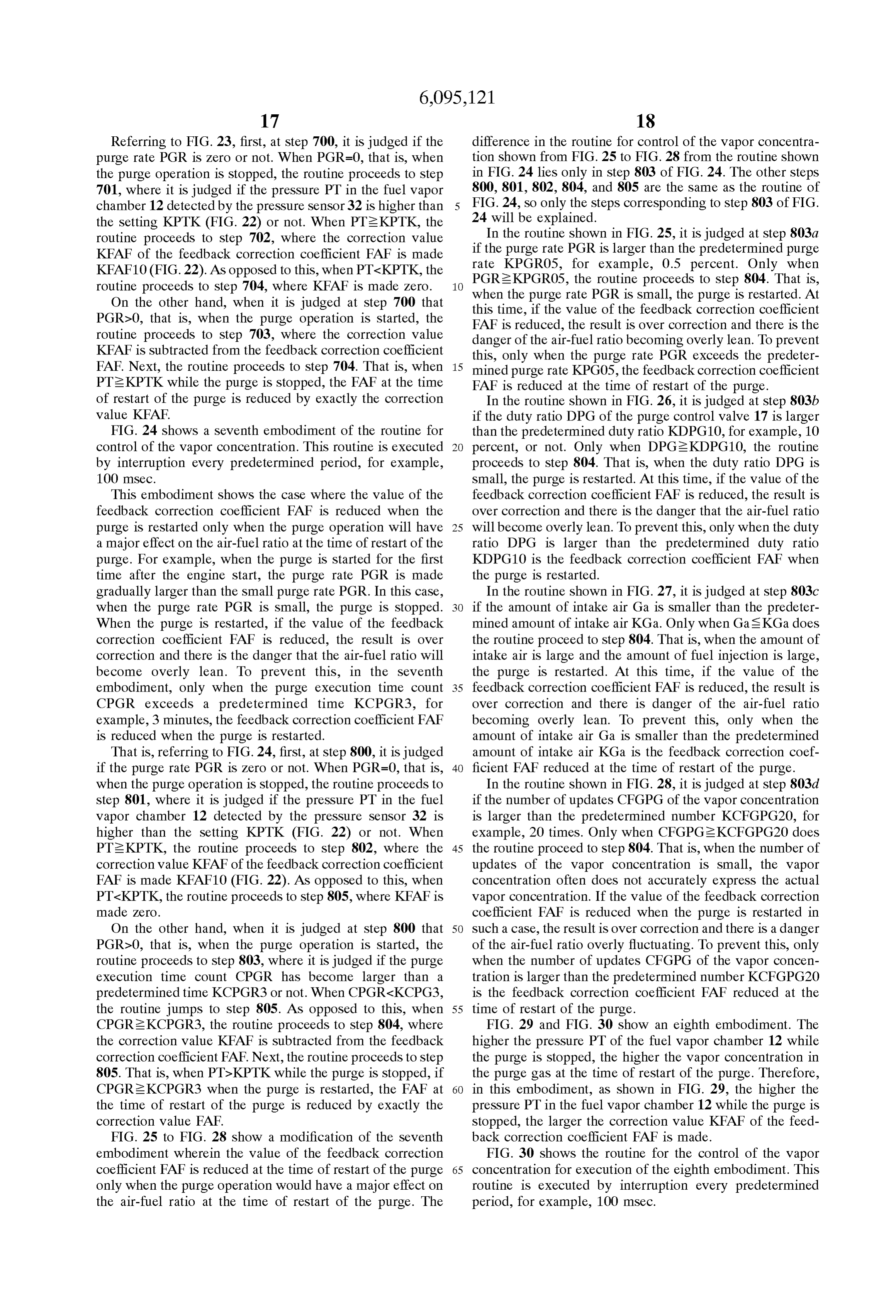
Referring to FIG. 30, first, at step 900, it is judged if the the upper space of the fuel tank 15 to the purge control valve purge rate PGR is zero or not. When PGR=0, that is, when 17 while the purge is stopped is the Same, the higher the the purge operation is stopped, the routine proceeds to Step purge rate PGR at the time of restart of the purge, the larger 901, where it is judged if the pressure PT in the fuel vapor the amount of deviation of the air-fuel ratio at the time of chamber 12 detected by the pressure sensor 32 is higher than restart of the purge. Therefore, in this embodiment, the the setting KPTK (FIG.22) or not. When PT2KPTK, the feedback correction coefficient FAF is found based on the routine proceeds to step 902, where the correction value following equation:
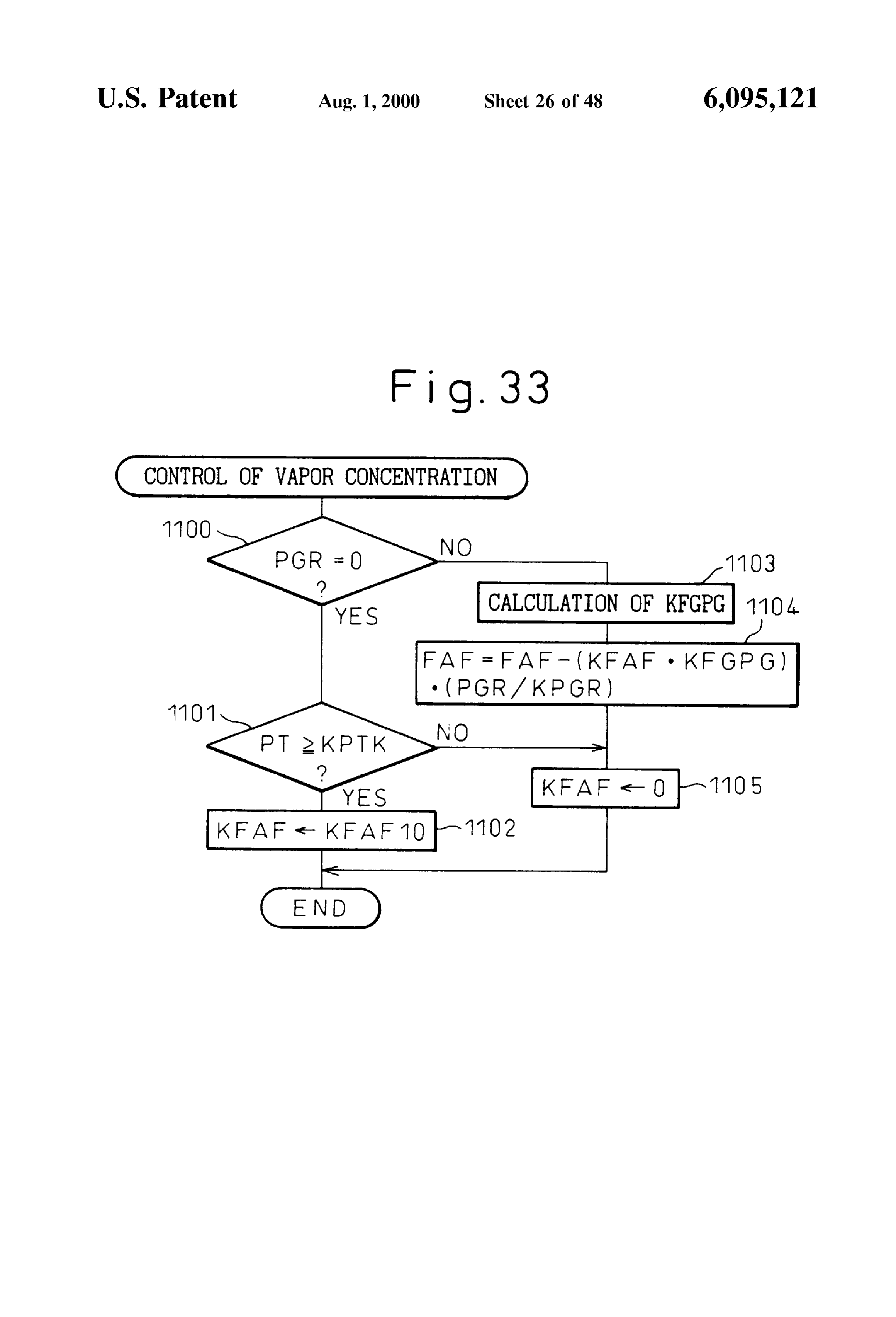
KFAF of the feedback correction coefficient FAF is calcu lated based on the pressure PT from the relationship shown in FIG. 29. As opposed to this, when PT-KPTK, the routine Here, KPGR is a predetermined reference purge rate. proceeds to step 904, where KFAF is made zero. Therefore, in this embodiment, the correction value KFAF is On the other hand, when it is judged at step 900 that multiplied with the above-mentioned correction coefficient PGR20, that is, when the purge operation is started, the KFGPG and further multiplied with ratio of the purge rate routine proceeds to step 903, where the correction value
KFAF is Subtracted from the feedback correction coefficient 15 PGR to the reference purge rate KPGR (PGR/KPGR) to calculate the final correction value.
FAF. Next, the routine proceeds to step 904. That is, if FIG. 33 shows the routine for control of the vapor PTeKPTK while the purge is stopped, the FAF at the time concentration for execution of the 10th embodiment. This of restart of the purge is reduced by exactly the correction routine is executed by interruption every predetermined value KFAF.
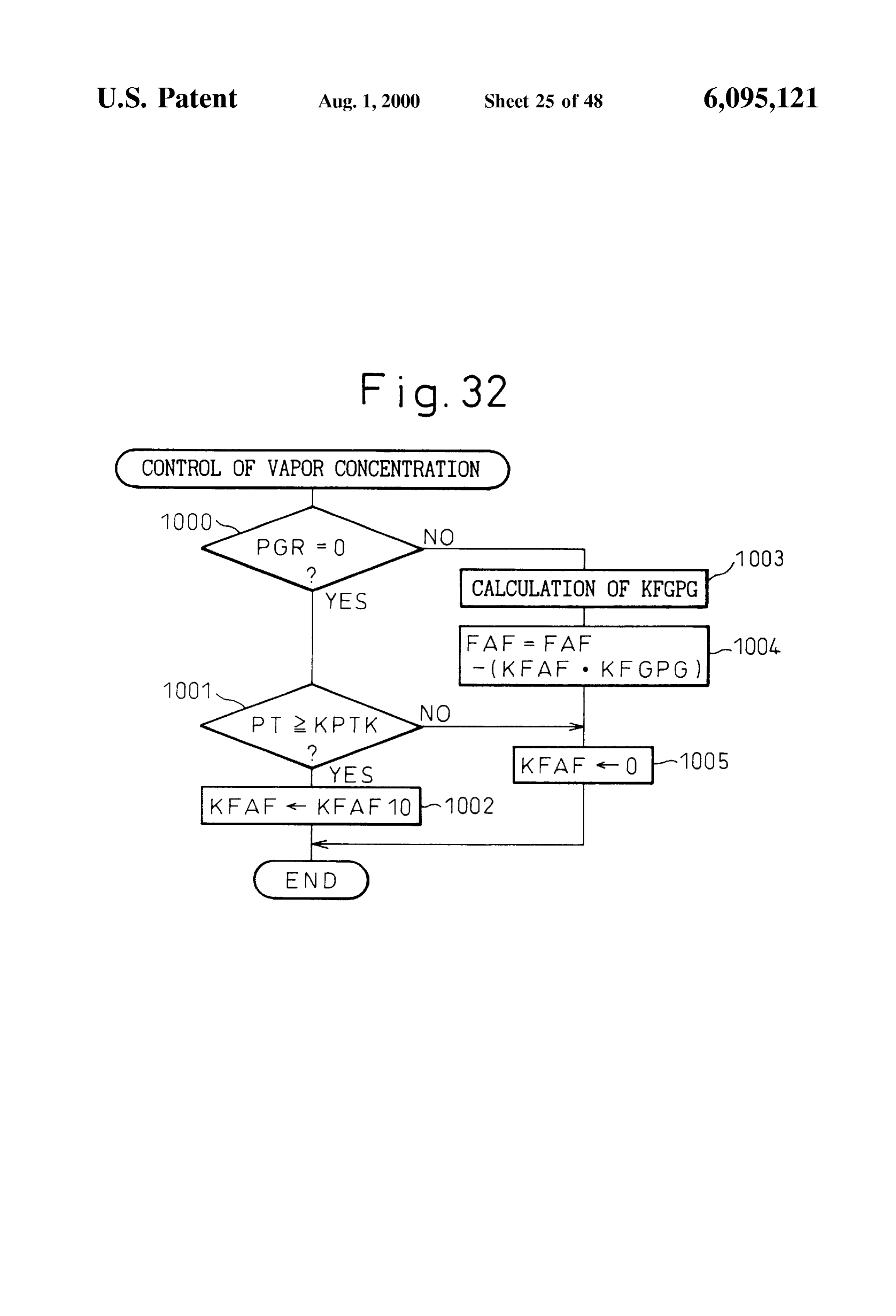
FIG. 31 and FIG. 32 shown a ninth embodiment. Even if period, for example, 100 mSec.
the amount of increase of the vapor concentration of the fuel purge Referring to FIG. 33, first, at step 1100, it is judged if the Vapor in the upper Space of the fuel tank 15 or the purge the purge rate PGR is zero or not. When PGR=0, that is, when passage from the upper space of the fuel tank 15 to the purge 1101, where operation is stopped, the routine proceeds to Step control valve 17 becomes large, the larger the vapor con chamber 12 detected it is judged if the pressure PT in the fuel vapor centration FGPG immediately before the purge is stopped, 25 the setting KPTK (FIG. by the pressure sensor 32 is higher than the Smaller the ratio of change of the vapor concentration routine proceeds to step 22) or not. When PT2KPTK, the 1102, where the correction value
FGPG at the time of restart of the purge to the vapor KFAF of the feedback correction coefficient FAF is made concentration FGPG immediately before the stopping of the KFAF10 (FIG.22). As opposed to this, when PT-KPTK, the purge. Therefore, in this embodiment, the correction coef routine proceeds to step 1105, where KFAF is made Zero. ficient KFGPG is multiplied with the correction value KFAF to find the final correction value (KFAF. KFGPG). This PGR20, that is, when when
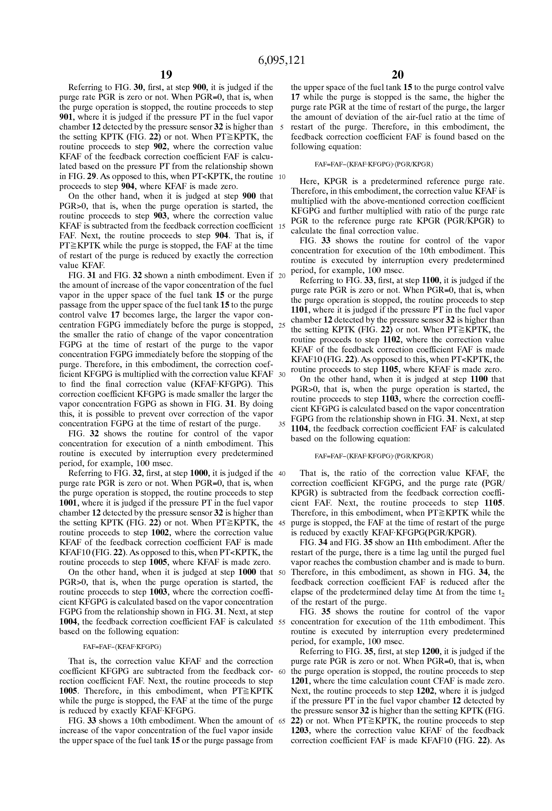
On the other hand, the it is judged at step 1100 that purge operation is started, the correction coefficient KFGPG is made smaller the larger the routine proceeds to step 1103, where the correction coeffi vapor concentration FGPG as shown in FIG. 31. By doing cient KFGPG is calculated based on the vapor concentration this, it is possible to prevent over correction of the vapor FGPG from the relationship shown in FIG. 31. Next, at step concentration FGPG at the time of restart of the purge. 35 1104, the feedback correction coefficient FAF is calculated FIG. 32 shows the routine for control of the vapor based on the following equation:
concentration for execution of a ninth embodiment. This routine is executed by interruption every predetermined period, for example, 100 mSec.
Referring to FIG. 32, first, at step 1000, it is judged if the 40 That is, the ratio of the correction value KFAF, the purge rate PGR is zero or not. When PGR=0, that is, when correction coefficient KFGPG, and the purge rate (PGR/ the purge operation is stopped, the routine proceeds to Step KPGR) is subtracted from the feedback correction coeffi 1001, where it is judged if the pressure PT in the fuel vapor cient FAF. Next, the routine proceeds to step 1105. chamber 12 detected by the pressure sensor 32 is higher than Therefore, in this embodiment, when PT2KPTK while the the setting KPTK (FIG.22) or not. When PT2KPTK, the 45 purge is Stopped, the FAF at the time of restart of the purge routine proceeds to step 1002, where the correction value is reduced by exactly KFAF. KFGPG(PGR/KPGR). KFAF of the feedback correction coefficient FAF is made FIG. 34 and FIG. 35 show an 11th embodiment. After the KFAF10 (FIG.22). As opposed to this, when PT-KPTK, the restart of the purge, there is a time lag until the purged fuel routine proceeds to step 1005, where KFAF is made zero. Vapor reaches the combustion chamber and is made to burn. On the other hand, when it is judged at step 1000 that 50 Therefore, in this embodiment, as shown in FIG. 34, the PGR20, that is, when the purge operation is started, the feedback correction coefficient FAF is reduced after the routine proceeds to step 1003, where the correction coeffi elapse of the predetermined delay time At from the time t cient KFGPG is calculated based on the vapor concentration of the restart of the purge.
FGPG from the relationship shown in FIG. 31. Next, at step FIG. 35 shows the routine for control of the vapor 1004, the feedback correction coefficient FAF is calculated 55 concentration for execution of the 11th embodiment. This based on the following equation: routine is executed by interruption every predetermined period, for example, 100 mSec.
Referring to FIG. 35, first, at step 1200, it is judged if the
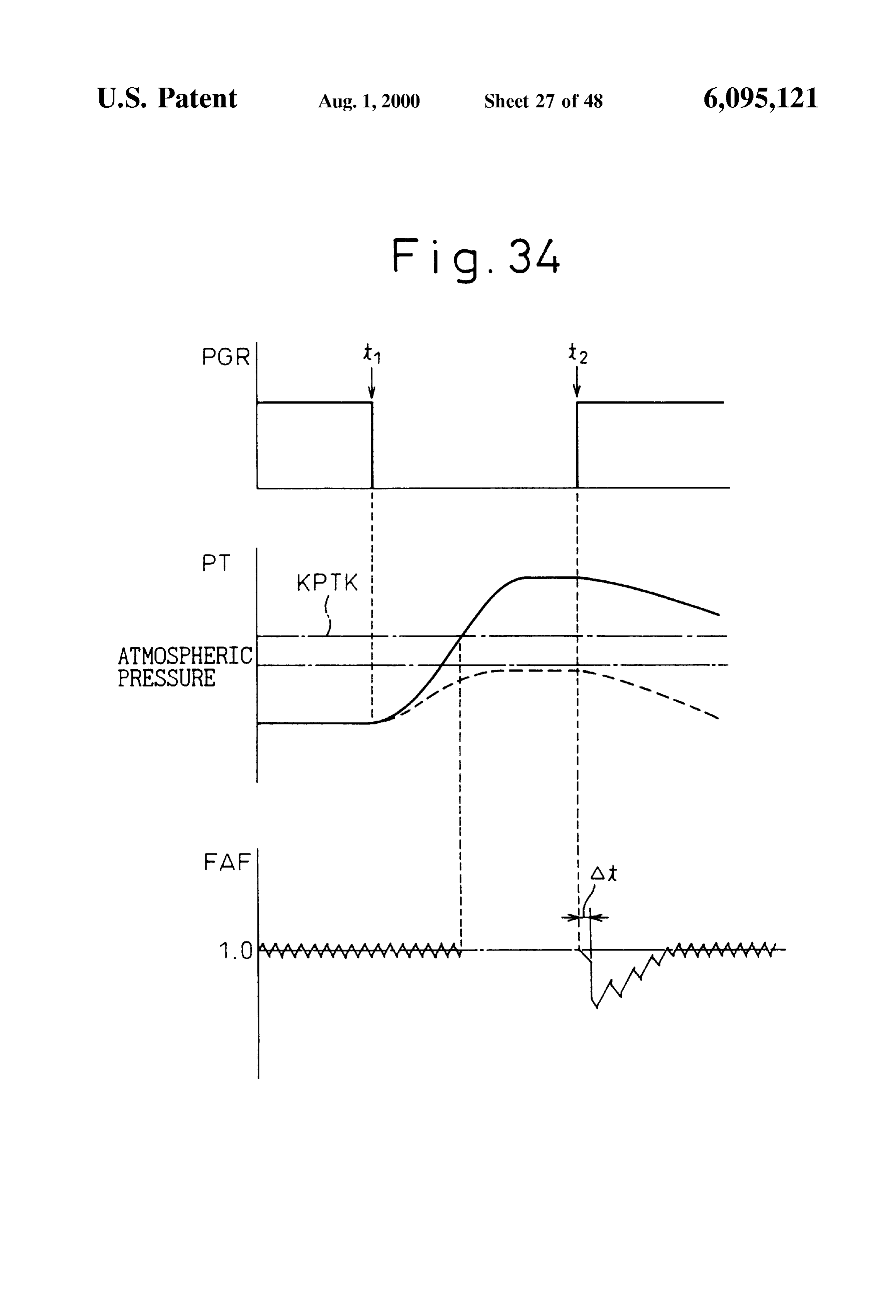
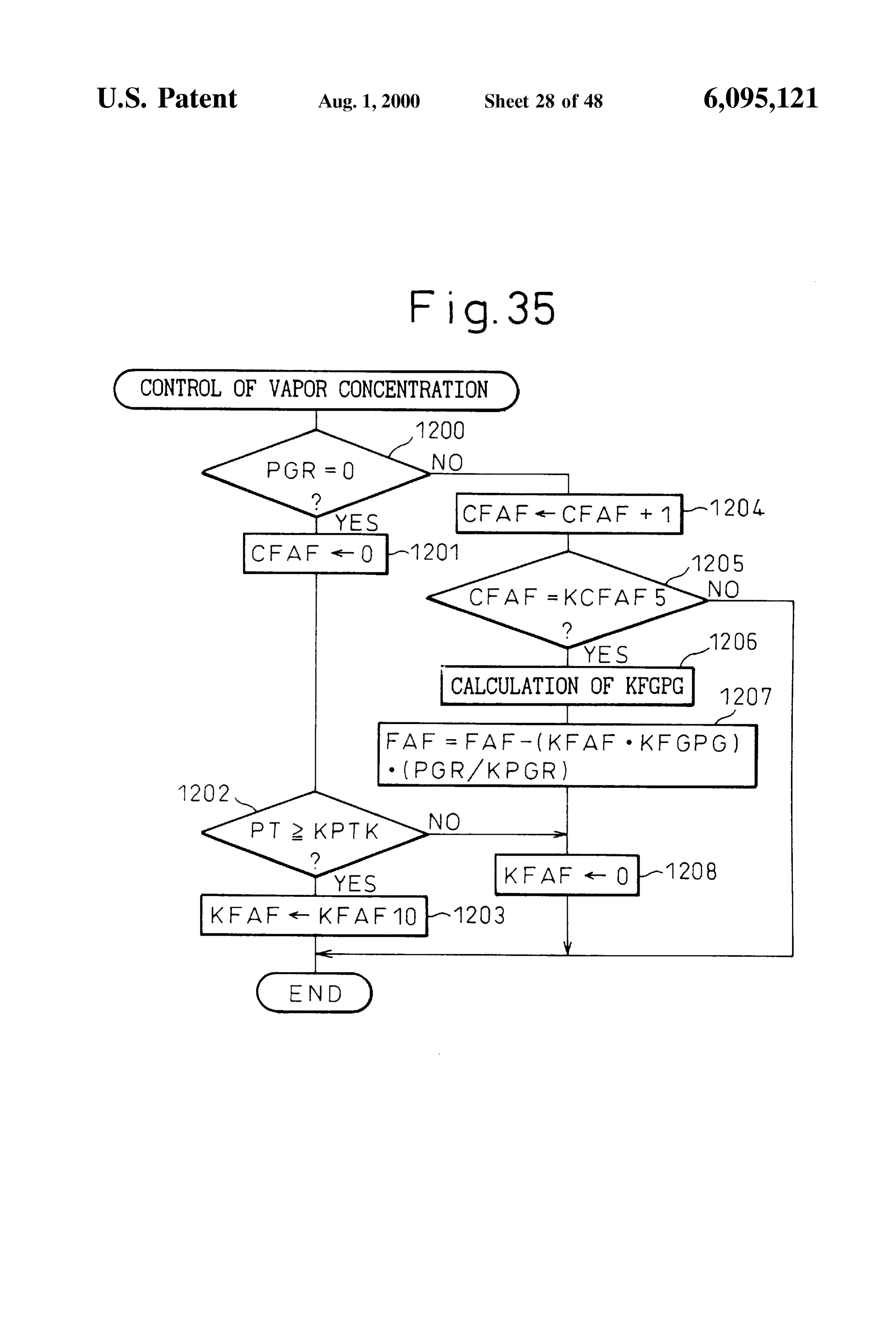
That is, the correction value KFAF and the correction purge rate PGR is zero or not. When PGR=0, that is, when coefficient KFGPG are subtracted from the feedback cor 60 the purge operation is stopped, the routine proceeds to Step rection coefficient FAF. Next, the routine proceeds to step 1201, where the time calculation count CFAF is made Zero. 1005. Therefore, in this embodiment, when PT2KPTK Next, the routine proceeds to step 1202, where it is judged while the purge is stopped, the FAF at the time of the purge if the pressure PT in the fuel vapor chamber 12 detected by is reduced by exactly KFAF. KFGPG. the pressure sensor 32 is higher than the setting KPTK(FIG. FIG. 33 shows a 10th embodiment. When the amount of 65 22) or not. When PT2KPTK, the routine proceeds to step increase of the vapor concentration of the fuel vapor inside 1203, where the correction value KFAF of the feedback the upper Space of the fuel tank 15 or the purge passage from correction coefficient FAF is made KFAF10 (FIG. 22). As
Page 60
opposed to this, when PT-KPTK, the routine proceeds to time. At shown in FIG. 36 has been reached from when the step 1208, where KFAF is made Zero. purge is restarted or not. When CFAF-KCFAF5, the pro On the other hand, when it is judged at step 1200 that cessing cycle ends. AS opposed to this, when PGR20, that is, when the purge operation is started, the CFAFeKCFAF5, the routine proceeds to step 1306, where routine proceeds to Step 1204, where the time calculation the correction coefficient KFGPG is calculated from the count CFAF is incremented by exactly 1. Next, at step 1205, relationship shown in FIG. 31 based on the vapor concen it is judged if the time calculation count CFAF has reached tration FGPG. Next, at step 1307, the feedback correction the predetermined count KCFAF5 or not, that is, if the delay coefficient FAF is calculated based on the following equa time. At shown in FIG. 34 has been reached from the restart tion:
of the purge. When CFAF is not KCFAF5, the processing cycle is ended. As opposed to this, when CFAF=KCFAF5, the routine proceeds to step 1206, where the correction Next, at step 1308, it is judged if the time calculation coefficient KFGPG is calculated based on the vapor con count CFAF has exceeded the predetermined count centration FGPG from the relationship shown in FIG. 31. KCFAF15 or not, that is, if the time range At 1 of FIG. 36 has Next, at step 1207, the feedback correction coefficient FAF been exceeded
or not. When CFAF-KCFAF15, the process is calculated based on the following equation: ing cycle ends. As opposed to this, when CFAFeKCFAF15, the routine proceeds to step 1309. That is, when PT2KPTK while the purge is stopped, when a predetermined delay time
Next, the routine proceeds to step 1208. That is, if At has elapsed after the restart of the purge, FAF is reduced PTeKPTK while the purge is stopped, when the predeter in stages by KFAF. KFGPG (PGR/KPGR)/KM at a time for mined delay time At elapses after the restart of the purge, the predetermined time At1.
FAF is reduced by exactly KFAF. KFGPG (PGR/KPGR). FIG. 38 and FIG. 39 show a 13th embodiment. In this FIG. 36 and FIG. 37 show a 12th embodiment. As embodiment, as shown in FIG. 38, the feedback correction explained above, as mentioned above, not only is there a 25 coefficient FAF is reduced in stages until the air-fuel ratio time delay after the restart of the purge until the purged fuel becomes lean after the purge is restarted. By doing this, it is Vapor has reached the combustion chamber and is burned, possible to inhibit over correction of FAF. but also the purged fuel vapor mixes with the intake air in FIG. 39 shows the routine for control of the vapor the Surge tank 5 and then is Successively Supplied to the concentration for execution of the 13th embodiment. This cylinders, So the vapor concentration in the intake air routine is executed by interruption every predetermined Supplied to the cylinderS Successively increases in Stages. period, for example, 100 mSec.
Therefore, in this embodiment, as shown in FIG. 36, after Referring to FIG. 39, first, at step 1400, it is judged if the the predetermined delay time At elapses from the time t of purge rate PGR is zero or not. When PGR=0, that is, when the restart of the purge, the feedback correction coefficient the purge operation is stopped, the routine proceeds to Step FAF is reduced little by little in stages across the predeter 35 1401, where the time calculation count CFAF is made Zero. mined time At1. Next, the routine proceeds to step 1402, where it is judged To reduce the feedback correction coefficient FAF in if the pressure PT in the fuel vapor chamber 12 detected by Stages in this way, in this embodiment, the feedback cor the pressure sensor 32 is higher than the setting KPTK(FIG. rection coefficient FAF is calculated based on the following 22) or not. When PT2KPTK, the routine proceeds to step equation: 40 1403, where the correction value KFAF of the feedback correction coefficient FAF is made KFAF10 (FIG. 22). As opposed to this, when PT-KPTK, the routine proceeds to
Here, KM is a value from 4 to about 8. That is, in this step 1409, where KFAF is made Zero. embodiment, FAF is reduced in stages by fractions of PGR20, On the other hand, when it is judged at step 1400 that KFAF. KFGPG (PGR/KPGR). 45 that is, when the purge operation is started, the routine proceeds
FIG. 37 shows the routine for the control of the vapor count CFAF is incremented to step 1404, where the time calculation concentration for execution of the 12th embodiment. This by exactly 1. Next, at step 1405, routine is executed by interruption every predetermined a predetermined count KCFAF5 count it is judged if the time calculation CFAF has exceeded or not, that is, if a delay period, for example, 100 mSec.
Referring to FIG. 37, first, at step 1300, it is judged if the 50 time.
purge
At shown in FIG. 38 has been reached from when the is restarted or not. When CFAF-KCFAF5, the pro purge rate PGR is zero or not. When PGR=0, that is, when cessing cycle ends. AS opposed to this, when the purge operation is stopped, the routine proceeds to Step CFAF-KCFAF5, the routine proceeds to step 1406, where 1301, where the time calculation count CFAF is made Zero. the correction coefficient KFGPG is calculated from the Next, the routine proceeds to step 1302, where it is judged relationship shown in FIG. 31 based on the vapor concen if the pressure PT in the fuel vapor chamber 12 detected by 55 the pressure sensor 32 is higher than the setting KPTK(FIG. tration FGPG. Next, at step 1407, the feedback correction 22) or not. When PT2KPTK, the routine proceeds to step coefficient FAF is calculated based on the following equa tion:
1303, where the correction value KFAF of the feedback correction coefficient FAF is made KFAF10 (FIG. 22). As opposed to this, when PT-KPTK, the routine proceeds to 60 step 1309, where KFAF is made Zero. Next, at step 1408, it is judged if the air-fuel ratio has On the other hand, when it is judged at step 1300 that become lean from the output signal of the O sensor. When PGR20, that is, when the purge operation is started, the the air-fuel ratio is not lean, the processing cycle ends. AS routine proceeds to step 1304, where the time calculation opposed to this, when the air-fuel ratio has become lean, the count CFAF is incremented by exactly 1. Next, at step 1305, 65 routine proceeds to step 1409. That is, when PT2KPTK it is judged if the time calculation count CFAF has exceeded while the purge has stopped, FAF is reduced in Stages by a predetermined count KCFAF5 or not, that is, if a delay KFAF-KFGPG (PGR/KPGR)/KM at a time until the air-fuel
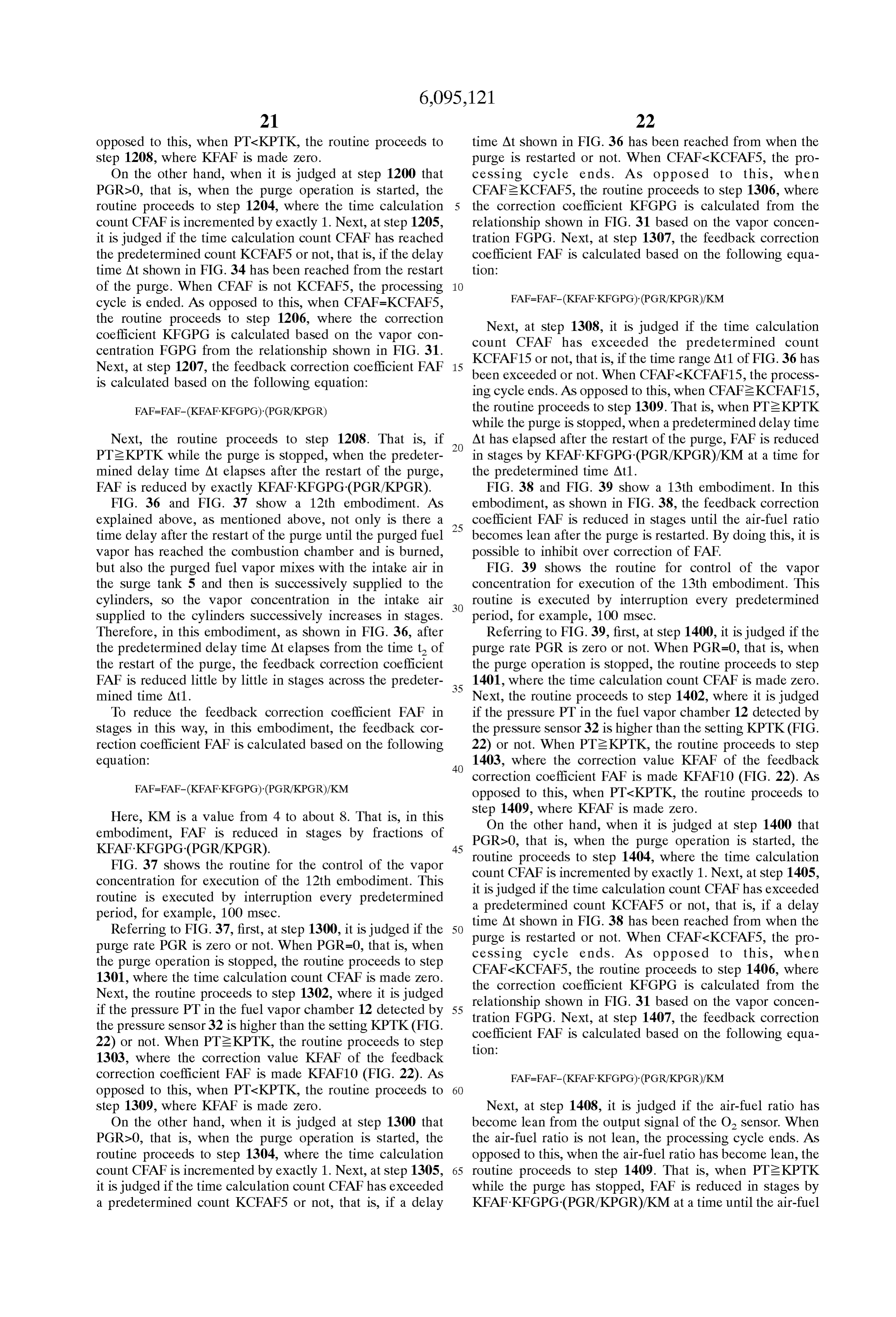
Page 61
ratio becomes lean after the elapse of the predetermined proceeds to Step 1502, where it is judged if the purge delay time At after the restart of the purge. stopping time count CPGROF is larger than the setting FIG. 40 to FIG. 42 show a 14th embodiment. First, KCUT. When CPGROFeKCUT, the routine proceeds to explaining FIG. 40, FIG. 40 shows the first purge stopping step 1503.
action I and the Second purge Stopping action II. t and t At step 1503, it is judged if the vapor concentration show the purge Stopping timing and the purge restarting increase flag XVAPOR has been set or not. When timing in the first purge stopping action I. t3 and t show the XVAPOR=0, that is, when the vapor concentration increase purge Stopping timing and the purge restarting timing in the flag XVAPOR has been reset, the routine proceeds to step Second purge action II. 1504, where it is judged if the number CSKIP of skips S of In this embodiment, it is judged if vapor concentration of the feedback correction coefficient FAF after the start of the the fuel vapor in the upper Space in the fuel tank 15 and in purge is smaller than 3 or not. When CSKIPs3, the routine the purge passage from the upper Space in the fuel tank 15 proceeds to step 1505, where it is judged if the feedback to the purge control valve 17 has increased while the purge correction coefficient FAF has become Smaller than the is stopped from the change in the feedback correction setting KFAFO9 (FIG. 40) or not. When FAFs KFAF09, the coefficient FAF after the start of the purge. For example, in 15 routine proceeds to step 1506, where the vapor concentra FIG. 40, if vapor concentration of the fuel vapor in the upper tion increase flag XVAPOR is set. That is, when CSKIPs3, Space in the fuel tank 15 and in the purge passage from the if FAFs KFAFO9, the vapor concentration increase flag upper space in the fuel tank 15 to the purge control valve 17 XVAPOR is set. Next, at step 1507, the purge time count has increased in the first purge Stopping period I, the CPGRON is made 1.
feedback correction coefficient FAF becomes Smaller imme If the vapor concentration increase flag XVAPOR is set, diately after the restart of the purge (t of FIG. 40). In the at the next processing cycle, the routine proceeds from Step example shown in FIG. 40, it is judged that the vapor 1503 to step 1513, where the purge time count CPGRON is concentration of the fuel vapor in the upper Space in the fuel incremented by exactly 1. Next, at step 1514, it is judged if tank 15 and in the purge passage from the upper Space in the the vapor concentration increase flag XVAPOR is set and if fuel tank 15 to the purge control valve 17 has increased 25 the purge time count CPGRON is 1 or not. At this time, while the purge is Stopped when the feedback correction XVAPOR=1, but CPGRON=2, so the processing cycle ends. coefficient FAF has become smaller than the predetermined At this time, the vapor concentration FGPG is not corrected. setting KFAFO9, for example, 0.9. At this time, the vapor Next, assuming that the purge is once again Stopped and concentration increase flag XVAPOR showing that the vapor that then the purge is restarted, at this time the vapor concentration has increased is Set. concentration increase flag XVAPOR is already set, so the Once the vapor concentration increase flag XVAPOR is routine proceeds from step 1503 to 1513. At this time, the Set, the purge is Stopped, then the vapor concentration FGPG purge time count CPGRON becomes 1. Therefore, at step is made to increase by exactly the predetermined correction 1514, it is judged that XVAPOR=1 and CPGRON=1, so the value KFGPG each time the purge is restarted, in the routine proceeds to step 1515 where the predetermined example shown in FIG. 40, at the purge restart time t after 35 correction value KFGPG is added to the vapor concentration the Second purge Stopping period II. If the vapor concen FGPG. Therefore, as explained above referring to FIG. 40, tration FGPG is made to increase when the purge is restarted it is possible to inhibit fluctuation of the air-fuel ratio A/F at in this way, the feedback correction coefficient FAF is the time of restart of the purge.
maintained at the reference value (= 1.0) and the air-fuel ratio FIG. 43 to FIG. 45 shows a 15th embodiment. In this A/F is maintained at the Stoichiometric air-fuel ratio when 40 embodiment, when the vapor concentration at the time of the purge is restarted. restart of the purge increases more than a predetermined FIG. 41 and FIG. 42 show the routine for control of the value, it is judged that the vapor concentration of the fuel Vapor concentration for execution of a 14th embodiment. Vapor in the upper Space of the fuel tank 15 or the purge This routine is executed by interruption every predetermined passage from the upper space of the fuel tank 15 to the purge period, for example, 100 mSec. 45 control valve 17 has increased while the purge is stopped. Referring to FIG. 41 and FIG. 42, first, at step 1500, it is That is, in FIG. 43, at the restart of the purge after the first judged if the purge time execution count CPGR is larger purge Stopping period I, when the vapor concentration than the setting KCPGR3 or not, for example, if 3 minutes FGPG has become larger than the setting KFG compared have elapsed from when the purge operation is started after with the vapor concentration FGPGOF immediately before the engine operation has started. When CPGR2KCPGR3, 50 the purge has stopped, that is, when FGPGeFGPGOF+ the routine proceeds to step 1508, where the vapor concen KFG, the vapor concentration increase flag XVAPOR is set. tration increase flag XVAPOR is reset. Next, at step 1509, it Then, when the purge is stopped and then the purge is is judged if the purge rate PGRO at the previous processing restarted, the vapor concentration FGPG is made to increase cycle was Zero or not. When PGR=0, the routine proceeds to by exactly the predetermined correction value KFGPG. step 1510, where the purge stopping time count CPGROF 55 FIG. 44 and FIG. 45 show the routine for control of the showing the purge Stopping time is incremented by exactly Vapor concentration for execution of a 15th embodiment. 1, then the routine proceeds to Step 1512. AS opposed to this, This routine is executed by interruption every predetermined when PGRO is not zero, the routine proceeds to step 1511, period, for example, 100 mSec.
where the purge stopping time count CPGROF is made Zero, Referring to FIG. 44 and FIG. 45, first, at step 1600, it is then the routine proceeds to step 1512. At step 1512, the 60 judged if the purge time execution count CPGR is larger purge time count CPGRON showing the purge continuation than the setting KCPGR3 or not, for example, if 3 minutes time is made Zero, then the processing cycle ends. have elapsed from when the purge operation is started after On the other hand, when it is judged at step 1500 that the engine operation has started. When CPGR2KCPGR3, CPGR2KCPGR3, the routine proceeds to step 1501, it is the routine proceeds to step 1608, where the vapor concen judged if the purge rate PGR is zero or not. When PGR=0, 65 tration increase flag XVAPOR is reset. Next, at step 1609, it the routine proceeds to step 1509. As opposed to this, when is judged if the purge rate PGRO at the previous processing PGR20, that is, when the purge is started, the routine cycle was Zero or not. When PGR=0, the routine proceeds to
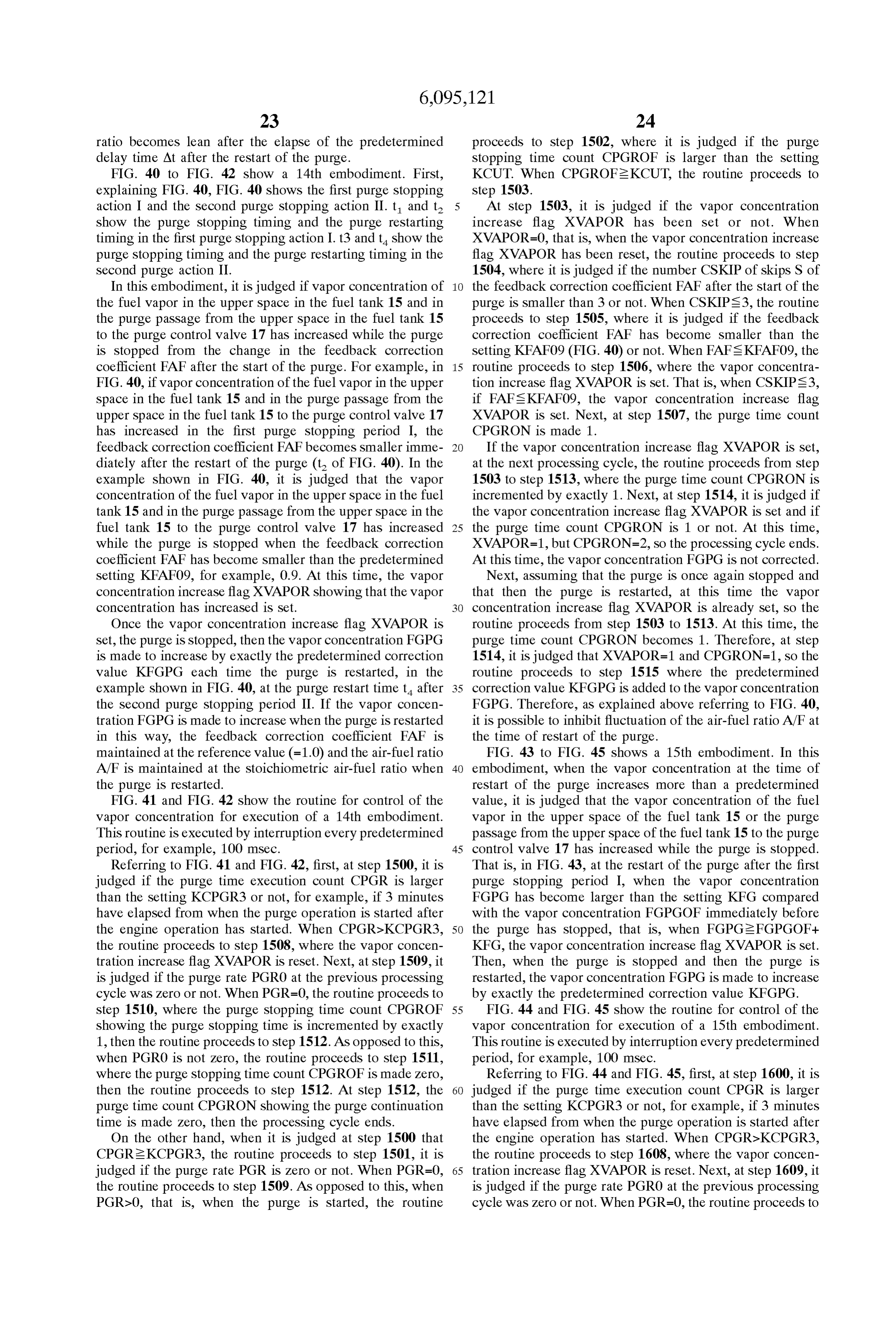
Page 62
step 1610, where the purge stopping time count CPGROF After the start of the purge, if FGPG2FGPGOF+KFG showing the purge Stopping time is incremented by exactly and the vapor concentration increase flag XVAPOR is set, at 1, then the routine proceeds to Step 1612. AS opposed to this, the next processing cycle, the routine proceeds from Step when PGRO is not zero, the routine proceeds to step 1611, 1703 to step 1714. At step 1714, it is judged if the vapor where the purge stopping time count CPGROF is made Zero, concentration increase flag XVAPOR is set, the skip number then the routine proceeds to step 1612. At step 1612, the CSKIP is not more than 6, and the purge time count vapor concentration FGPG is made FGPGOF. Next, at step CPGRON is at least 1. At this time, XVAPOR=1 and 1613, the purge time count CPGRON showing the purge CPGRON21, so if CSKIP<6, the routine proceeds to step continuation time is made Zero, then the processing cycle 1715, where the difference of the current vapor concentra ends.
On the other hand, when it is judged at step 1600 that tion FGPG minus the vapor concentration FGPGOF imme CPGR2KCPGR3, the routine proceeds to step 1601, it is diately before the purge has stopped (FGPG-FGPGOF) is made the correction value KFGPG.
judged if the purge rate PGR is zero or not. When PGR=0, Next, at step 1716, the purge time count CPGRON is the routine proceeds to step 1609. As opposed to this, when
PGR20, that is, when the purge is started, the routine 15 incremented by exactly 1. Next, at step 1717, it is judged if proceeds to Step 1602, where it is judged if the purge the vapor concentration increase flag XVAPOR is set and the stopping time count CPGROF is larger than the setting purge time count CPGRON is 1. At this time, XVAPOR=1, KCUT. When CPGROFeKCUT, the routine proceeds to but CPGRON=2, so the processing cycle ends. At this time, step 1603. the vapor concentration FGPG is not corrected. At step 1603, it is judged if the vapor concentration At the next processing cycle, So long as SKIPS6, the increase flag XVAPOR has been set or not. When routine proceeds from step 1714 to step 1715, where the XVAPOR=0, that is, when the vapor concentration increase correction value KFGPG is updated. When SKIP=6, the flag XVAPOR has been reset, the routine proceeds to step learning of the vapor concentration FGPG is substantially 1604, where it is judged if the number CSKIP of skips S of completed. Therefore, the correction value KFGPG substan the feedback correction coefficient FAF after the start of the tially matches the amount of increase of the vapor concen purge is smaller than 6 or not. When CSKIPs 6, the routine 25 tration FGPG.
proceeds to step 1605, where it is judged if the vapor Next, assuming that the purge is again Stopped and then concentration FGPG has become larger than the sum the purge is restarted, at this time, the vapor concentration (FGPGOF+KFG) of the vapor concentration FGPGOF increase flag XVAPOR is already set, so the routine pro immediately before the purge was stopped and the Setting ceeds from step 1703 to 1714. At this time, the purge time KFG. When FGPG2FGPGOF+KFG, the routine proceeds to step 1606, the vapor concentration increase flag XVAPOR count CPGRON is zero, so the routine jumps from step 1714 to step 1716. At step 1716, the purge time count CPGRON is set. That is, when CSKIPs 6, if FGPGs FGPOF+KFG, the vapor concentration increase flag XVAPOR is set. Next, becomes 1. Therefore, at the next step 1717, it is judged that at step 1607, the purge time count CPGRON is made 1. XVAPOR=1 and CPGRON=1, so the routine proceeds to If the purge concentration increase flag XVAPOR is set, step 1718, where the already calculated correction value at the next processing cycle, the routine proceeds from Step 35 KFGPG is added to the vapor concentration FGPG. 1603 to step 1614, where the purge time count CPGRON is Therefore, it is possible to inhibit fluctuation of the air-fuel incremented by exactly 1. Next, at step 1615, it is judged if ratio A/F at the time of restart of the purge. the vapor concentration increase flag XVAPOR is set and the At the next processing cycle, if CSKIPs 6, the routine purge time count CPGRON is 1 or not. At this time, proceeds to step 1715, where the correction value KFGPG XVAPOR=1, but CPGRON=2, so the processing cycle ends. 40 is again updated.
At this time, the vapor concentration FGPG is not corrected. FIG. 49 to FIG. 50 show a 17th embodiment. In this Next, assuming that the purge is again Stopped and then embodiment, the correction value AFGPG per unit purge the purge is restarted, at this time, the vapor concentration stopping time is found. The final correction value KFGPG, increase flag XVAPOR is already set, so the routine pro which is proportional to the purge Stopping time, is found ceeds to step 1603 to step 1614. At this time, the purge time 45 from this correction value AFGPG. Specifically, the final count CPGRON becomes 1. Therefore, at the next step correction value KFGPG is calculated based on the follow 1615, it is judged if XVAPOR=1 and CPGRON=1, so the ing equation:
routine proceeds to Step 1616, where the predetermined correction value KFGPG is added to the vapor concentration AFGPG=(FGPG-FGPGOF)-KCPGROF/CPGROF (1) FGPG. Therefore, it is possible to inhibit the fluctuation of 50 KFGPG=AFGPG (CPGROF/KCPGROF) (2) the air-fuel ratio A/F at the time of restart of the purge.
FIG. 46 to FIG. 48 shows a 16th embodiment. In this Here, KCPGROF is the reference purge stopping time, for embodiment, as shown in FIG. 46, Substantially the entire example, 10 Sec.
KFGPG of the amount of increase of the vapor concentra Explaining this using FIG. 46, CPGROF in equation (1) tion FGPG after the first purge stopping period I is made the 55 shows the first purge Stopping period I, therefore the cor correction value KFGPG of the vapor concentration at the rection value AFGPG per 10 Seconds of purge Stopping time time of restart of the purge after the Second purge Stopping is found from equation (1).
period II. As opposed to this, CPGROF in equation (2) shows the FIG. 47 and FIG. 48 show the routine for control of the Second purge Stopping period II. Therefore, the final cor Vapor concentration for execution of a 16th embodiment. 60 rection value KFGPG is increased the longer the purge This routine is executed by interruption every predetermined Stopping time.
period, for example, 100 msec. Note that the routine from FIG. 49 and FIG. 50 shows the routine for control of the step 1700 to step 1713 of FIG. 47 is the same as that of step Vapor concentration. This routine is executed by interruption 1600 to step 1613 of FIG. 44. The difference from the every predetermined period, for example, every 100 mSec. routine shown in FIG. 44 and FIG. 45 lies in the part after 65 Note that step 1800 to step 1813 of FIG. 49 are the same as step 1714 of FIG. 48. Below, step 1714 of FIG. 48 on will step 1600 to step 1613 of FIG. 44. The difference from the be explained. routine shown in FIG. 44 and FIG. 45 lies in the part after
Page 63
step 1814 of FIG. 50. The explanation will therefore be At step 1916, the purge time count CPGRON is incre made of step 1814 on in FIG. 50. mented by exactly 1. Next, at step 1917, it is judged if the If, after the start of the purge, FGPG2FGPGOF+KFG vapor concentration increase flag XVAPOR has been set and and the vapor concentration increase flag XVAPOR is set, at the purge time count CPGRON is KCPG. At this time, the next processing cycle, the routine proceeds from Step XVAPOR=1, but CPGRON=2 (<KCPG), so the processing 1803 to step 1814. At step 1814, it is judged if the vapor cycle ends. At this time, the vapor concentration FGPG is concentration increase flag XVAPOR has been set, the skip not corrected.
number CSKIP is not more than 6, and the purge time count Next, if CPGRON becomes KCPG at step 1916, the CPGRON is at least 1. At this time, XVAPOR=1 and routine proceeds to step 1918. When the routine proceeds to CPGRON21, so if CSKIPs 6, the routine proceeds to step step 1918 for the first time after the engine operation is 1815, where the correction value AFGPG per unit purge started, AFGPG is not yet calculated and AFGPG has Stopping time is calculated based on the following equation become Zero, so the correction value KFGPG becomes Zero. using the current vapor concentration FGPG, the vapor Therefore, even at this time, the vapor concentration FGPG concentration FGPGOF immediately before the purge was is not corrected.
Stopped, the reference purge Stopping time KCPGROF, and 15 On the other hand, if CPGRON becomes KCPG, at the the purge Stopping time count CPGROF showing the purge next processing cycle, if CSKIPS6, the routine proceeds Stopping time: from step 1914 to step 1915, where the correction value AFGPG=(FGPG-FGPGOF). KCPGROF/CPGROF AFGPG per unit purge Stopping time is calculated based on the following equation using the current vapor concentration
Next, at step 1816, the purge time count CPGRON is FGPG, the vapor concentration FGPGOF immediately incremented by exactly 1. Next, at step 1817, it is judged if before the purge was Stopped, the reference purge Stopping the vapor concentration increase flag XVAPOR has been set time KCPGROF, and the purge stopping time count and the purge time count CPGRON is 1. At this time, CPGROF showing the purge stopping time:
XVAPOR=1, but CPGRON=2, so the processing cycle ends.
At this time, the vapor concentration FGPG is not corrected. 25 AFGPG=(FGPG-FGPGOF)-KCPGROF/CPGROF At the next processing cycle, So long as SKIPS6, the Next, at step 1916, CPGRON becomes KCPG+1, so the routine proceeds from step 1814 to step 1815, where AFGPG routine proceeds to Step 1917 and the processing cycle ends. if updated. At the next processing cycle, So long as SKIPS6, the Next, assuming that the purge is stopped and then the routine purge is restarted, at this time, the vapor concentration AFGPG proceeds from step 1914 to step 1915, where the is updated.
increase flag XVAPOR is already set, so the routine pro ceeds from step 1803 to step 1814. At this time, the purge theNext, assuming that the purge has again stopped and then purge is restarted, the vapor concentration increase flag time count CPGRON is Zero, So the routine jumps from Step XVAPOR is already set, so the routine proceeds from step 1814 to step 1816. At step 1816, the purge time count 1903 to step 1914. At this time, the purge time count CPGRON becomes 1. Therefore, at the next step 1817, it is CPGRON is zero,
so the routine jumps from step 1914 to judged that XVAPOR=1 and CPGRON=1, so the routine step 1916.
proceeds to step 1818, where the final correction value Next, at step 1916, if CPGRON becomes KCPG, the KFGPG is calculated based on the following equation: routine proceeds from step 1917 to step 1918, where the KFGPG=AFGPG (CPGROF/KCPGROF) final correction value KFGPG is calculated based on the
following equation:
Next, at step 1819, the correction value KFGPG is added to the vapor concentration KFPG. At the next processing KFGPG=AFGPG (CPGROF/KCPGROF) cycle, if CSKIPs 6, the routine proceeds to step 1815, where
AFGPG is again updated. Next, at step 1919, the correction value KFGPG is added FIG. 51 and FIG. 52 shows an 18th embodiment. In this 45 to the vapor concentration FGPG. That is, when the purge is embodiment, the delay time from when the purge is restarted restarted, when CPGRON has become KCPG after the to when the purged fuel vapor reaches the combustion restart of the purge, that is, a predetermined time after the chamber, the corrective action of the vapor concentration restart of the purge, the vapor concentration FGPG is FGPG at the restart of the purge is delayed by exactly a corrected. At the next processing cycle, if CSKIPs 6, the predetermined time until the purge time count CPGRON 50 routine proceeds to step 1915, where AFGPG is again becomes the predetermined value KCPG. updated.
FIG. 51 and FIG. 52 shows the routine for control of the Next, an explanation will be given of the case where the Vapor concentration. This routine is executed every prede vapor concentration increase flag XVAPOR is reset if the termined period, for example, every 100 msec. Note that correction would become over correction when for example step 1900 to step 1913 of FIG. 51 is the same as step 1600 55 correcting the vapor concentration FGPG when the purge is to step 1613 of FIG. 44. The difference with the routine restarted. FIG. 53 shows the case where the correction shown in FIG. 44 and FIG. 45 lies in the part after step 1914 would become over correction when the vapor concentration of FIG. 52, so the explanation will be made below of step is corrected at the time t of the restart of purge. When the 1914 on of FIG 52. correction would become over correction in this way, as After the start of the purge, if FGPG2FGPGOF+KFG 60 shown in FIG. 53, the feedback correction coefficient FAF and the vapor concentration increase flag XVAPOR is set, at becomes larger and the vapor concentration FGPG rapidly the next processing cycle, the routine proceeds from Step falls.
1903 to step 1914. At step 1914, it is judged if the vapor Therefore, in the routine for control of the vapor concen concentration increase flag XVAPOR has been set, the skip tration increase flag XVAPOR shown in FIG. 54, when the number CSKIP is not more than 6, and the purge time count 65 feedback correction coefficient FAF exceeds the predeter CPGRON is at least KCPG. At this time, XVAPOR=1, but mined value KFAF11, for example, 1.1, within a certain CPGRON is 1, so the routine jumps to step 1916. period after the restart of the purge as shown in FIG. 53, it
Page 64
is judged if the vapor concentration increase flag XVAPOR first fuel Supply correcting means for controlling an is reset and the vapor concentration of the fuel vapor in the amount of fuel Supply based on an air-fuel ratio upper space of the fuel tank 15 or the purge passage from the detected by the air-fuel ratio detecting means So that an upper space of the fuel tank 15 to the purge control valve 17 air-fuel ratio approaches a target air-fuel ratio; while the purge is Stopped again has increased or not. In the Vapor concentration calculating means for calculating an routine for control of the vapor concentration increase flag
XVAPOR shown in FIG.55, as shown in FIG. 53, when the intake passage vapor concentration of fuel vapor Sup vapor concentration FGPG has fallen more than the prede plied to the intake passage based on an amount of termined value FGPGOF+C. (C.20) in a predetermined deviation of the air-fuel ratio from the target air-fuel period after the restart of the purge, it is judged of the vapor 1O ratio, concentration increase flag XVAPOR has been reset and the Second fuel Supply correcting means for further correcting Vapor concentration of the fuel vapor in the upper space of the amount of fuel Supply based on the intake passage the fuel tank 15 or the purge passage from the upper space Vapor concentration So that the air-fuel ratio approaches of the fuel tank 15 to the purge control valve 17 while the the target air-fuel ratio; and purge is stopped again has increased or not.
Referring to FIG. 54, first, at step 2000, it is judged if the 15 concentration change detecting means for detecting, while purge Stopping time count CPGROF has become larger than a purge operation is stopped, a change of a purge the predetermined time KCUT or not. When System vapor concentration of fuel vapor in one of the CPGROF2KCUT, the routine proceeds to step 2001, where upper Space of the fuel tank and a portion of the purge it is judged if the purge time count CPGRON is larger than passage extending between the upper Space of the fuel the predetermined time KCPG or not. When tank and the purge control valve, one of the first fuel CPGRON2KCPG, the routine proceeds to step 2002, where Supply correcting means and the Second fuel Supply it is judged if the vapor concentration increase flag correcting means correcting the amount of fuel Supply XVAPOR has been set or not. in accordance with the detected concentration change When the vapor concentration increase flag XVAPOR has So that the air-fuel ratio immediately after a restart of been set, the routine proceeds to step 2003, where it is 25 the purge operation becomes the target air-fuel ratio. judged if the skip number CSKIP of the feedback correction 2. An evaporated fuel treatment device as Set forth in coefficient FAF is not more than 3. When CSKIPs3, the claim 1, wherein the Second fuel Supply correcting means routine proceeds to step 2004, where it is judged if the corrects the intake passaae vapor concentration in accor feedback correction coefficient FAF has become larger than dance with the detected concentration change So that the the predetermined value KFAF11. When FAFeKFAF11, the air-fuel ratio immediately after the restart of the purge routine proceeds to step 2005, where the vapor concentra operation becomes the target air-fuel ratio. tion increase flag XVAPOR is reset. 3. An evaporated fuel treatment device as Set forth in Next, referring to FIG.55 showing another embodiment, claim 2, wherein when the purge System Vapor concentration first, at Step 2100, it is judged if the purge Stopping time increases, the calculated intake passage vapor concentration count CPGROF is larger than a predetermined time KCUT 35 is increased.
or not. When CPGROF2KCUT, the routine proceeds to step 4. An evaporated fuel treatment device as Set forth in 2101, where it is judged if the purge time count CPGRON claim 2, wherein the concentration change detecting means is larger than the predetermined time KCPG or not. When detects the concentration change based on a pressure in one CPGRON2KCPG, the routine proceeds to step 2102, where of the upper Space of the fuel tank and the portion of the it is judged if the vapor concentration increase flag 40 purge passage extending between the upper Space of the fuel XVAPOR is set or not. tank and the purge control valve. When the vapor concentration increase flag XVAPOR is 5. An evaporated fuel treatment device as set forth in Set, the routine proceeds to Step 2103, where it is judged if claim 2, wherein the concentration change detecting means the skip number CSKIP of the feedback correction coeffi detects the concentration change based on a temperature in cient FAF is not more than 6. When CSKIPs 6, the routine 45 the fuel tank.
proceeds to step 2104, where it is judged if the vapor 6. An evaporated fuel treatment device as Set forth in concentration FGPG has become smaller than the predeter claim 2, wherein, after a start of the engine, the purge mined value FGPGOF+C. When FGPGs FGPGOF+C, the operation is first Started and then Stopped, before the con routine proceeds to Step 2105, where the vapor concentra centration change is detected and the intake passage vapor tion increase flag XVAPOR is reset. 50 concentration is corrected in accordance with the concen According to the present invention, as mentioned above, tration change.
it is possible to inhibit fluctuation of the air-fuel ratio when 7. An evaporated fuel treatment device as set forth in the purge operation is temporarily Stopped and then the claim 2, wherein, when a stopping period during which the purge operation is restarted. purge operation is Stopped is shorter than a predetermined While the invention has been described by reference to 55 period, correction of the vapor concentration by the Second Specific embodiments chosen for purposes of illustration, it fuel Supply correcting means is prohibited. should be apparent that numerous modifications could be 8. An evaporated fuel treatment device as set forth in made thereto by those skilled in the art without departing claim 1, wherein the first fuel Supply correcting means from the basic concept and Scope of the invention. controls the amount of fuel Supply based on a feedback What is claimed is: 60 correction coefficient which changes in accordance with the 1. An evaporated fuel treatment device for an engine detected air-fuel ratio So that the air-fuel ratio becomes a provided with an intake passage, comprising: target air-fuel ratio and wherein the first fuel Supply cor a fuel Vapor purge passage connecting an upper Space of recting means controls the value of the feedback correction a fuel tank and the intake passage; coefficient at the time of the restart of the purge operation a purge control Valve arranged in the purge passage; 65 based on the concentration change So that the air-fuel ratio air-fuel ratio detecting means for detecting an air-fuel immediately after the restart of the purge operation becomes ratio; the target air-fuel ratio.
Page 65
9. An evaporated fuel treatment device as set forth in 19. An evaporated fuel treatment device as set forth in claim 8, wherein the concentration change detecting means claim 18, wherein, when the purge System vapor concentra detects the concentration change based on a pressure in one tion increases while the purge operation is Stopped, when the of the upper Space of the fuel tank and the portion of the purge operation is restarted after being Stopped once, the purge passage extending between the upper Space of the fuel intake passage vapor concentration is increased by exactly a tank to the purge control valve. predetermined correction value. 10. An evaporated fuel treatment device as set forth in 20. An evaporated fuel treatment device as set forth in claim 8, wherein, when the purge System vapor concentra claim 19, wherein, when the air-fuel ratio at the start of the tion increases while the purge operation is Stopped, the value purge operation is Smaller than a predetermined air-fuel of the feedback correction coefficient at the restart of the ratio, it is judged that the purge System vapor concentration purge operation is reduced by a predetermined correction has increased while the purge operation was stopped. value. 21. An evaporated fuel treatment device as Set forth in 11. An evaporated fuel treatment device as Set forth in claim 19, wherein, when it is judged that the intake passage claim 10, wherein, when the pressure in the one of the upper Vapor concentration has exceeded a predetermined concen Space of the fuel tank and the portion of the purge passage 15 tration in a predetermined period after the Start of the purge, extending between the upper space of the fuel tank and the it is judged that the purge System vapor concentration has purge control valve increases while the purge operation is increased while the purge operation was Stopped. Stopped, the correction value is made larger. 22. An evaporated fuel treatment device as Set forth in 12. An evaporated fuel treatment device as Set forth in claim 21, wherein, when it is judged that the purge System claim 10, wherein, when the vapor concentration calculated Vapor concentration has increased while the purge operation by the vapor concentration calculation means increases, the was Stopped, the correction value is calculated as a value correction value is made Smaller. proportional to a difference obtained by Subtracting a first 13. An evaporated fuel treatment device as set forth in value of the intake passage vapor concentration immediately claim 10, wherein, when a purge rate of the fuel vapor before the purge operation was stopped from a Second value decreases, the correction value is made Smaller. 25 of the intake passage vapor concentration during a prede 14. An evaporated fuel treatment device as Set forth in termined period after the Start of the purge operation. claim 8, wherein, when the purge System vapor concentra 23. An evaporated fuel treatment device as set forth in tion increases while the purge operation is Stopped, the value claim 21, wherein, when it is judged that the purge System of the feedback correction coefficient when the purge opera Vapor concentration has increased while the purge operation tion is restarted is reduced in a plurality of Stages by a was stopped, the correction value is calculated based on a predetermined correction value. difference obtained by subtracting a first value of the intake 15. An evaporated fuel treatment device as set forth in passage vapor concentration immediately before the purge claim 8, wherein when the purge System vapor concentration operation was stopped from a second value of the intake increases while the purge operation is stopped, the value of passage vapor concentration during a predetermined period the feedback correction coefficient when the purge operation 35 after the Start of the purge operation and a purge Stopping is restarted is reduced in a plurality of Stages by a prede period during which the purge operation is Subsequently termined correction value until the air-fuel ratio becomes Stopped again and wherein the correction value is propor lean. tional to the difference and proportional to the purge Stop 16. An evaporated fuel treatment device as set forth in ping period.
claim 8, wherein when the purge System vapor concentration 40 24. An evaporated fuel treatment device as Set forth in increases while the purge operation is stopped, the value of claim 19, wherein, when the air-fuel ratio is Smaller than a the feedback correction coefficient is reduced by a prede predetermined air-fuel ratio when the intake passage vapor termined correction value only when one of the following concentration has been increased by exactly the predeter conditions exists: a purge execution time after a Start of the mined correction value, the intake passage vapor concen engine is longer than a predetermined time, a purge rate of 45 tration is increased by exactly a predetermined amount each the fuel vapor is higher than a predetermined purge rate; an time the purge operation is restarted until the air-fuel ratio opening degree of the purge control valve is larger than a exceeds a predetermined air-fuel ratio after the intake pas predetermined opening degree; an amount of intake air is Sage vapor concentration has been increased by the correc Smaller than a predetermined amount; and a number of tion value, and wherein, when the air-fuel ratio exceeds the updates of the purge System vapor concentration is larger 50 predetermined air-fuel ratio after the intake passage Valpor than a predetermined number. concentration has been increased by the correction value, it 17. An evaporated fuel treatment device as set forth in is again judged whether the vapor concentration should be claim 8, wherein, when the purge System vapor concentra corrected when the purge operation is next stopped and then tion increaseS while the purge operation is Stopped, a pre restarted and, based on this judgement, the intake passage determined time after the restart of the purge operation the 55 Vapor concentration is corrected when the purge operation is value of the feedback correction coefficient is reduced by a next Stopped and then restarted.
predetermined correction value. 25. An evaporated fuel treatment device as set forth in 18. An evaporated fuel treatment device as set forth in claim 19, wherein, when the intake passage vapor concen claim 1, wherein the concentration change detecting means tration remains larger than a predetermined concentration detects the concentration change based on a in one of the 60 for a predetermined period after the intake passage vapor air-fuel ratio and the intake passage vapor concentration concentration has been increased by the correction value, the when the purge operation has been Started and wherein the intake passage vapor concentration is increased by exactly a Second fuel Supply correcting means corrects the intake predetermined amount every time the purge operation is passaae vapor concentration based on the concentration restarted and wherein when, during a predetermined period change So that the air-fuel ratio becomes the target air-fuel 65 after the intake passage vapor concentration has been ratio when the purge operation is Subsequently stopped once increased by the correction value, the intake passage vapor and the purge operation is restarted. concentration has become Smaller than a predetermined
Page 66
concentration, it is again judged whether the intake passage predetermined correction value a predetermined time after Vapor concentration should be corrected when the purge the purge operation is Subsequently stopped once and then restarted.
operation is next stopped and then restarted and, based on 27. An evaporated fuel treatment device as set forth in this judgement, the intake passage vapor concentration is claim 18, wherein the Second fuel Supply correcting means corrected when the purge operation is next Stopped and corrects the intake passage vapor concentration and wherein, restarted. when a stopping time during which the the purge operation 26. An evaporated fuel treatment device as Set forth in is Stopped is shorter than a predetermined period, correction claim 18, wherein, when the purge System vapor concentra of the intake passage vapor concentration by the Second fuel Supply correcting means is prohibited.
tion increases while the purge operation is Stopped, the intake passage vapor concentration is increased by exactly a k k k k k
Page 67
UNITED STATES PATENT AND TRADEMARK OFFICE
CERTIFICATE OF CORRECTION
PATENT NO. : 6,095,121 Page 1 of 1
INVENTOR(S) : Akinori Osanai
It is certified that error appears in the above-identified patent and that said Letters Patent is hereby corrected as shown below:
Column 7
Line 42, delete “once'.
Column 25
Line32, change “FGPG<FGPOF...” to -- FGPGFGPOF... --. Column 30
Line 28, change "passaae' to -- passage --. Column 31
Line 60, delete “a in'.
Signed and Sealed this
Twenty-ninth Day of April, 2003
JAMES E ROGAN
Director of the United States Patent and Trademark Office
Provenance
- Collection
- Cited prior art
- Original PDF
- patentimages.storage.googleapis.com →
- Filed
- 1998-09-21
- Pages
- 67
- Method
- pdftotext (the PDF's own text layer) + pdftoppm 300dpi page scans
- Source
- Google Patents bibliographic record
- Granted
- 2000-08-01
- Inventors
- Akinori Osanai; Toyota Motor Corp
- Transcribed from
- patentimages.storage.googleapis.com →