patent · US4312324
Wind loss prevention for open cavity solar receivers
26 January 1982
Page 1 — bibliographic record
United States Patent (19) 11 4,312,324 Ross et al. 45 Jan. 26, 1982
54 WIND LOSS PREVENTION FOR OPEN 56 References Cited CAVITY SOLAR RECEIVERS U.S. PATENT DOCUMENTS 897,290 9/1908 Jacobs ............................. 128/141 R 75 Inventors: Don H. Ross, Newton, Mass.; 2,182,222. 12/1939 Courtis ................................ 26/424 Theodore J. Nussdorfer, Nashua, 4,069,812 1/1978 O'Neill ................................ 126/439 N.H. Primary Examiner-Samuel Scott
Assistant Examiner-G. Anderson (73) Assignee: Sanders Associates, Inc., Nashua, Attorney, Agent, or Firm-Louis Etlinger; Ronald
21 Appi. No.: 160,036 Apparatus for minimizing thermal loss in a windowless, open cavity solar receiver due to airflow at the receiver 22 Filed: Jun. 6, 1980 aperture includes means for deflecting wind away from the cavity opening such that flow stream reattachment occurs away from the receiver aperture to provide a
Related U.S. Application Data dead air zone at the cavity opening. This prevents tur bulent-mixing airflow exchange between ambient air 63 Continuation of Ser. No. 932,170, Aug. 9, 1978, aban and heated air within the solar receiver. The wind de doned. flector apparatus includes either a passive annular de flection foil at the receiver aperture, or an active device
for producing an outwardly projected air jet at the 52 U.S. Cl. ................ ............................ 126/418 receiver aperture.
OPEN-CAVITY RECEIVER, to
\ BRAYTON st CYCLE
ENGINE
Page 2
Drawing sheet — no readable text.
Page 3
Drawing sheet — no readable text.
Page 4
Drawing sheet — no readable text.
Page 5
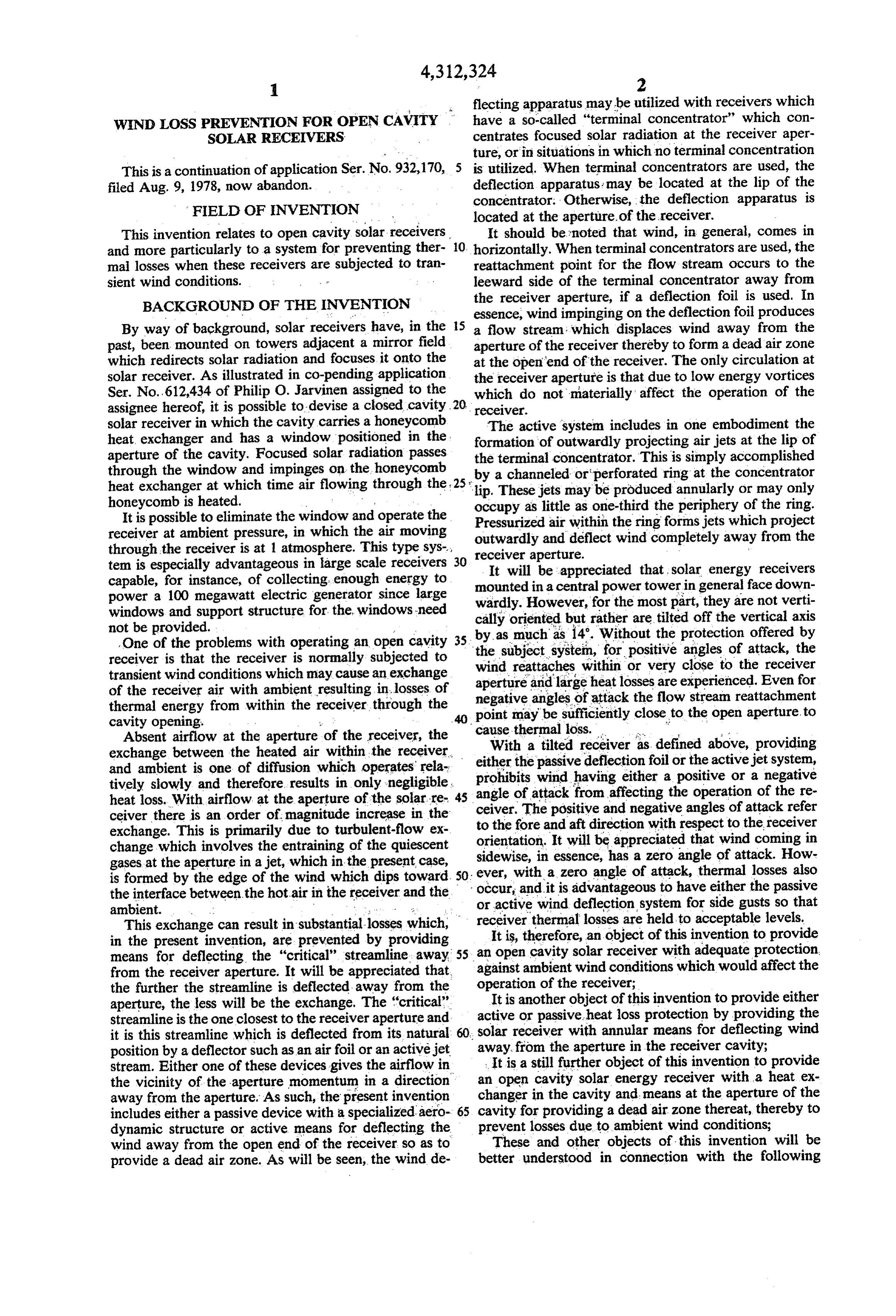
flecting apparatus may be utilized with receivers which wIND Loss PREVENTION FOR OPEN CAVITY have a so-called "terminal concentrator" which con SOLAR RECEIVERS centrates focused solar radiation at the receiver aper ture, or in situations in which no terminal concentration
This is a continuation of application Ser. No. 932,170, 5 is utilized. When terminal concentrators are used, the filed Aug. 9, 1978, now abandon. deflection apparatus may be located at the lip of the
FIELD OF NVENTION
concentrator. Otherwise, the deflection apparatus is located at the aperture of the receiver.
This invention relates to open cavity solar receivers O. It should be noted that wind, in general, comes in and more particularly to a system for preventing ther horizontally. When terminal concentrators are used, the mal losses when these receivers are subjected to tran reattachment point for the flow stream occurs to the sient wind conditions. leeward side of the terminal concentrator away from the receiver aperture, if a deflection foil is used. In
BACKGROUND OF THE INVENTION essence, wind impinging on the deflection foil produces By way of background, solar receivers have, in the 5 a flow stream, which displaces wind away from the past, been mounted on towers adjacent a mirror field aperture of the receiver thereby to form a dead air zone which redirects solar radiation and focuses, it onto the at the open end of the receiver. The only circulation at solar receiver. As illustrated in co-pending application the receiver aperture is that due to low energy vortices Ser. No. 612,434 of Philip O. Jarvinen assigned to the which do not materially affect the operation of the assignee hereof, it is possible to devise a closed cavity receiver.
solar receiver in which the cavity carries a honeycomb The active system includes in one embodiment the heat, exchanger and has a window positioned in the formation of outwardly projecting air jets at the lip of aperture of the cavity. Focused solar radiation passes the terminal concentrator. This is simply accomplished through the window and impinges on the honeycomb by a channeled or perforated ring at the concentrator heat exchanger at which time air flowing through the 25 s'lip. These jets may be produced annularly or may only honeycomb is heated. occupy as little as one-third the periphery of the ring. It is possible to eliminate the window and operate the Pressurized air within the ring forms jets which project receiver at ambient pressure, in which the air moving through the receiver is at 1 atmosphere. This type sys outwardly and deflect wind completely away from the tem is especially advantageous in large scale receivers 30 receiver aperture.
It will be appreciated that solar energy receivers capable, for instance, of collecting enough energy to mounted in a central power tower in general face down power a 100 megawatt electric generator since large wardly. However, for the most part, they are not verti windows and support structure for the windows need cally oriented but rather are tilted off the vertical axis not be provided. by as much as 14. Without the protection offered by One of the problems with operating an open cavity 35 receiver is that the receiver is normally subjected to the subject systein, for positive angles of attack, the transient wind conditions which may cause an exchange wind reattaches within or very close to the receiver of the receiver air with ambient resulting in...losses of negative and aperture large heat losses are experienced. Even for thermal energy from within the receiver, through the point mayangles of attack the flow stream reattachment be sufficiently close to the open aperture. to
Absent airflow at the aperture of the receiver, the cause thermal loss. a :' exchange between the heated air within the receiver. With a tilted receiver as defined above, providing and ambient is one of diffusion which operates' rela either the passive deflection foil or the active jet system, prohibits wind having either a positive or a negative tively slowly and therefore results in only negligible. angle of attack from affecting the operation of the re heat loss. With airflow at the aperture of the solar re 45 ceiver. The positive and negative angles of attack refer ceiver there is an order of magnitude increase in the exchange. This is primarily due to turbulent-flow ex to the fore and aft direction with respect to the receiver orientation. It will be appreciated that wind coming in change which involves the entraining of the quiescent sidewise, in essence, has a zero angle of attack. How gases at the aperture in a jet, which in the present case, is formed by the edge of the wind which dips toward. 50 ever, ev occur, with a zero angle of attack, thermal losses and it is advantageous to have either
the also passive the interface between the hot-air in the receiver and the ambient. or active wind deflection system for side gusts so that This exchange can result in substantial losses which, receiver thermal losses are held to acceptable levels. in the present invention, are prevented by providing anItopen is, therefore, an object of this invention to provide cavity solar receiver with adequate protection means for deflecting the "critical' streamline away 55 from the receiver aperture. It will be appreciated that, against ambient wind conditions which would affect the the further the streamline is deflected away from the operation of the receiver; It is another object of this invention to provide either aperture, the less will be the exchange. The "critical'.
streamline is the one closest to the receiver aperture and active or passive heat loss protection by providing the it is this streamline which is deflected from its natural 60. solar receiver with annular means for deflecting wind position by a deflector such as an airfoil or an active jet away from the aperture in the receiver cavity; stream. Either one of these devices gives the airflow in anItopen is a still further object of this invention to provide the vicinity of the aperture momentum in a direction changer incavity solar energy receiver with a heat ex the cavity and means at the aperture of the away from the aperture. As such, the present invention includes either a passive device with a specialized aero 65 cavity for providing a dead air zone thereat, thereby to dynamic structure or active means for deflecting the prevent losses due to ambient wind conditions; wind away from the open end of the receiver so as to These and other objects of this invention will be provide a dead air zone. As will be seen, the wind de better understood in connection with the following
Page 6
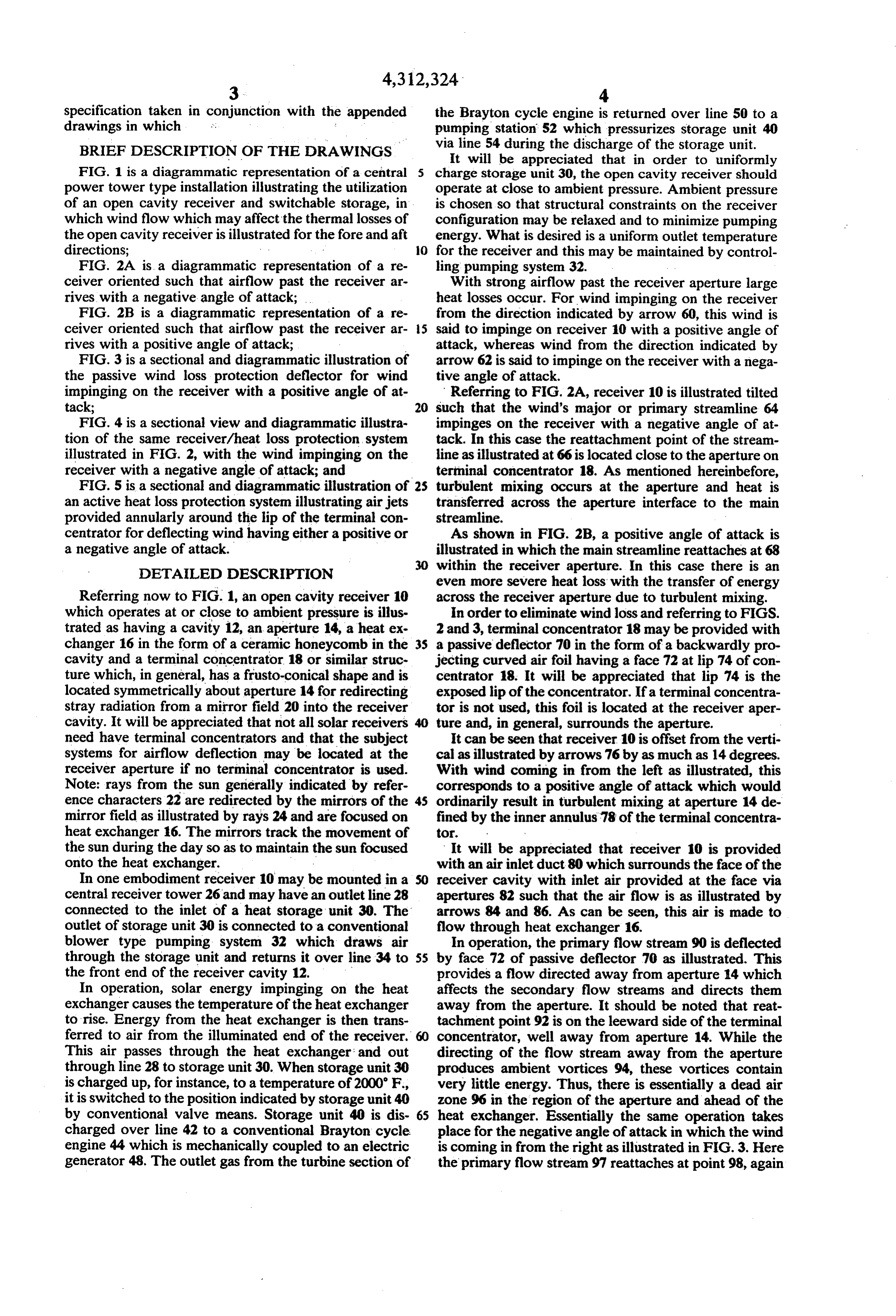
specification taken in conjunction with the appended the Brayton cycle engine is returned over line 50 to a drawings in which .. pumping station 52 which pressurizes storage unit 40 BRIEF DESCRIPTION OF THE DRAWINGs via line 54 during the discharge of the storage unit. It will be appreciated that in order to uniformly
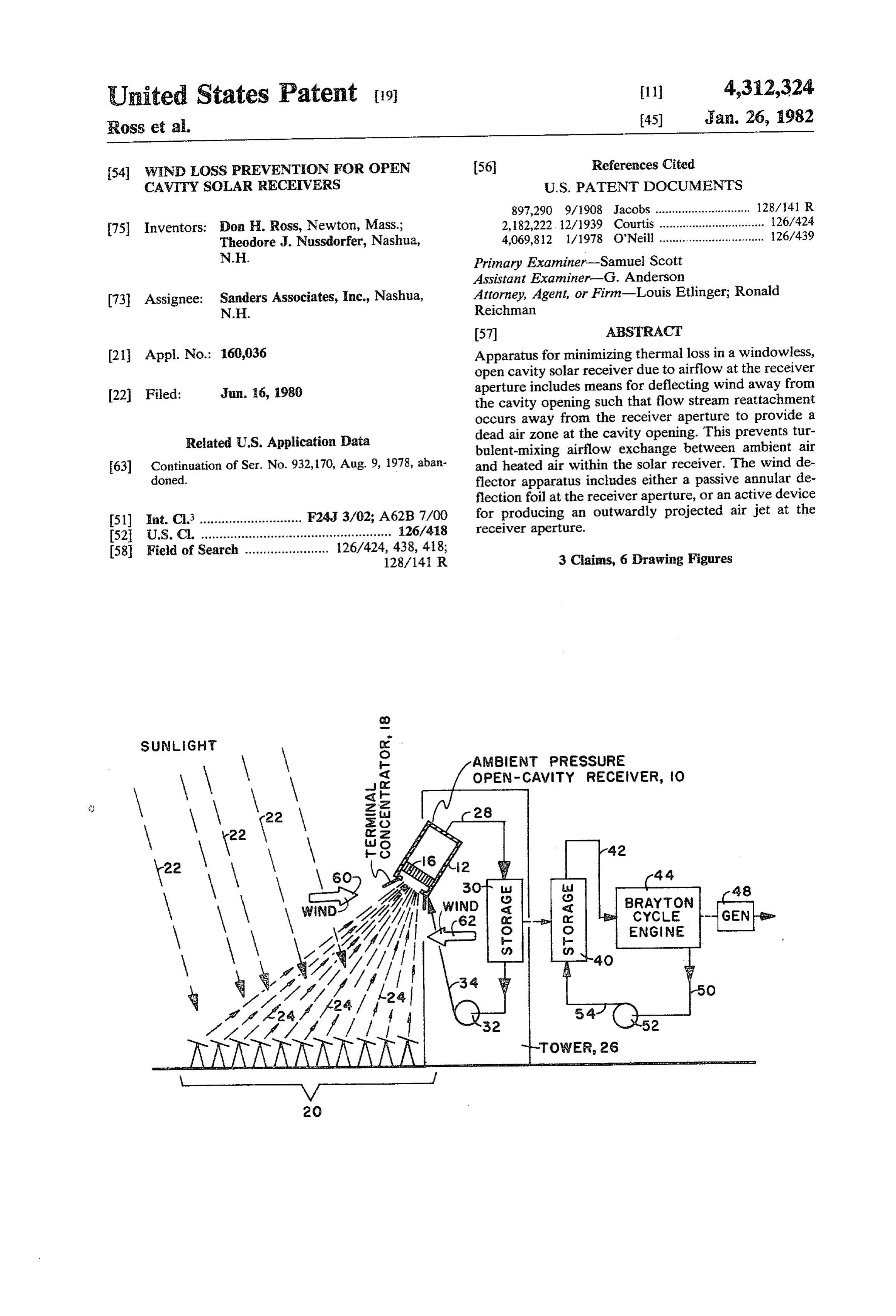
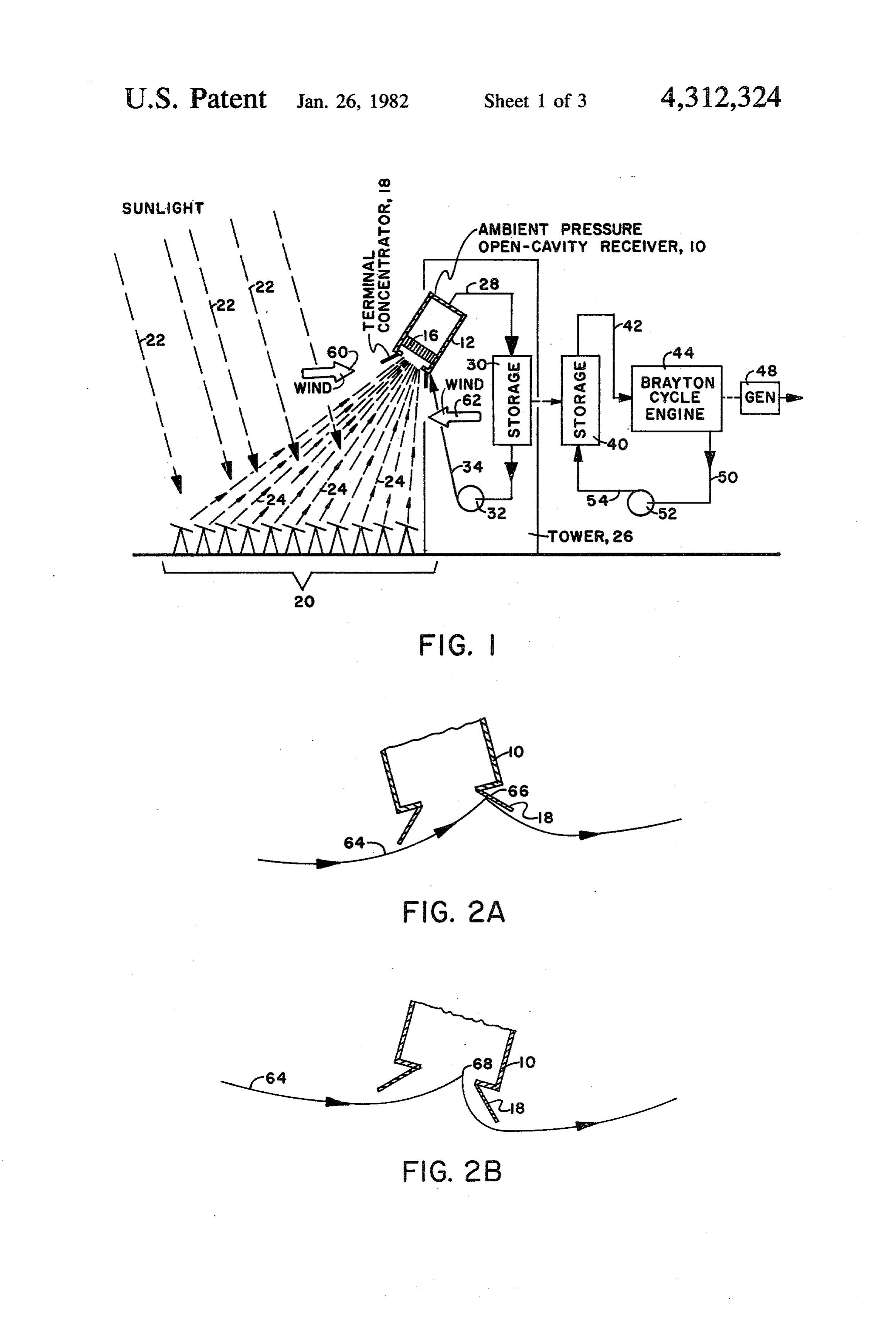
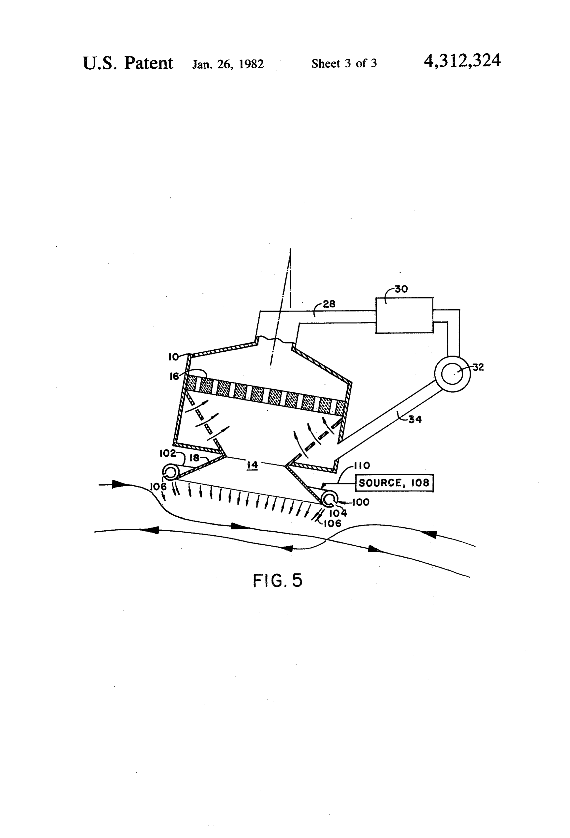
FIG. 1 is a diagrammatic representation of a central 5 charge storage unit 30, the open cavity receiver should power tower type installation illustrating the utilization operate at close to ambient pressure. Ambient pressure of an open cavity receiver and switchable storage, in is chosen so that structural constraints on the receiver which wind flow which may affect the thermal losses of configuration may be relaxed and to minimize pumping the open cavity receiver is illustrated for the fore and aft energy. What is desired is a uniform outlet temperature directions; - O for the receiver and this may be maintained by control FIG. 2A is a diagrammatic representation of a re ling pumping system 32.
ceiver oriented such that airflow past the receiver ar With strong airflow past the receiver aperture large rives with a negative angle of attack; heat losses occur. For wind impinging on the receiver FIG. 2B is a diagrammatic representation of a re from the direction indicated by arrow 60, this wind is ceiver oriented such that airflow past the receiver ar 5 said to impinge on receiver 10 with a positive angle of rives with a positive angle of attack; attack, whereas wind from the direction indicated by FIG. 3 is a sectional and diagrammatic illustration of arrow 62 is said to impinge on the receiver with a nega the passive wind loss protection deflector for wind tive angle of attack.
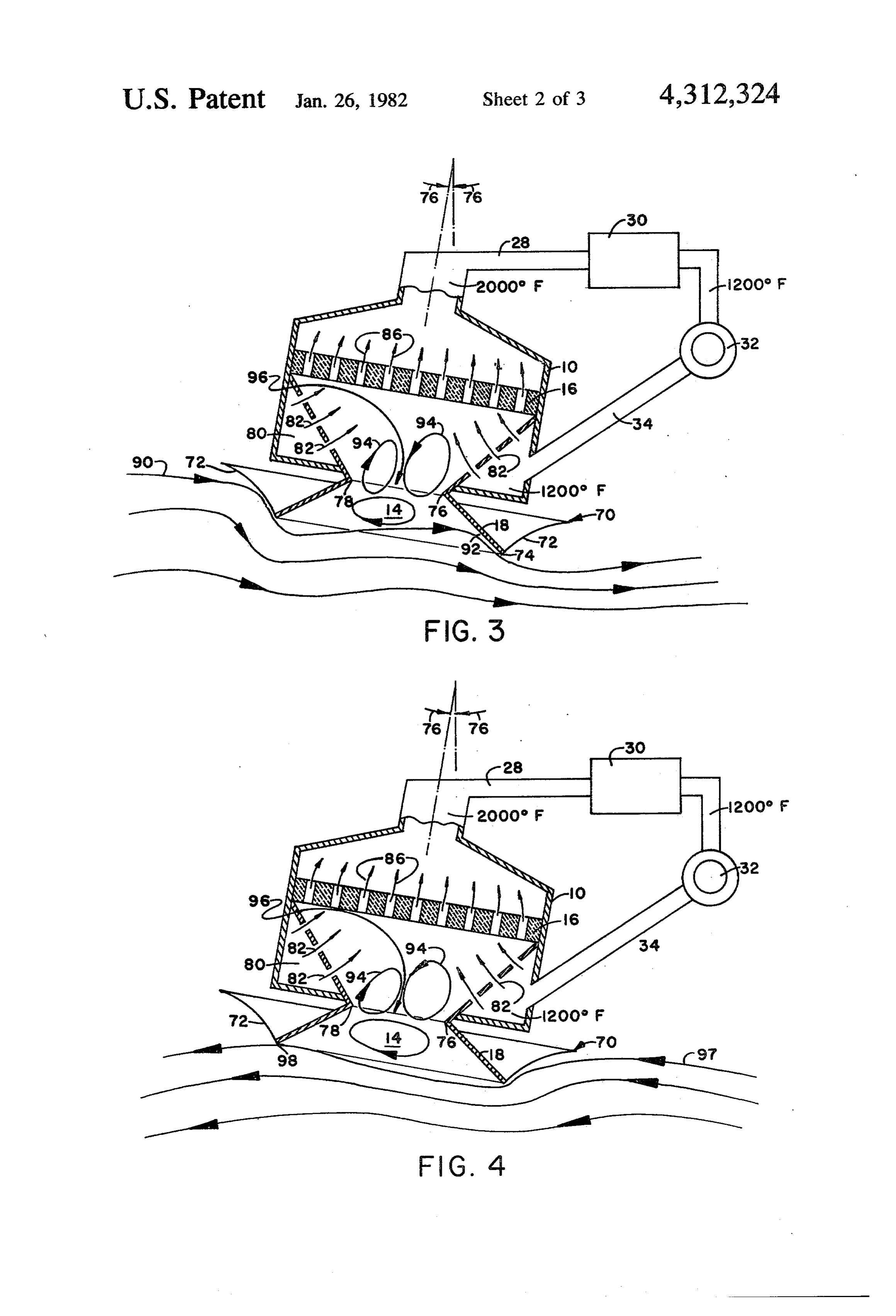
impinging on the receiver with a positive angle of at Referring to FIG. 2A, receiver 10 is illustrated tilted tack; 20 such that the wind's major or primary streamline 64 FIG. 4 is a sectional view and diagrammatic illustra impinges on the receiver with a negative angle of at tion of the same receiver/heat loss protection system tack. In this case the reattachment point of the stream illustrated in FIG. 2, with the wind impinging on the line as illustrated at 66 is located close to the aperture on receiver with a negative angle of attack; and terminal concentrator 18. As mentioned hereinbefore, FIG. 5 is a sectional and diagrammatic illustration of turbulent mixing occurs at the aperture and heat is an active heat loss protection system illustrating air jets transferred across the aperture interface to the main provided annularly around the lip of the terminal con streamline.
centrator for deflecting wind having either a positive or As shown in FIG. 2B, a positive angle of attack is a negative angle of attack. illustrated in which the main streamline reattaches at 68 DETALED DESCRIPTION within the receiver aperture. In this case there is an even more severe heat loss with the transfer of energy
Referring now to FIG. 1, an open cavity receiver 10 across the receiver aperture due to turbulent mixing. which operates at or close to ambient pressure is illus In order to eliminate wind loss and referring to FIGS. trated as having a cavity 12, an aperture 14, a heat ex 2 and 3, terminal concentrator 18 may be provided with changer 16 in the form of a ceramic honeycomb in the 35 a passive deflector 70 in the form of a backwardly pro cavity and a terminal concentrator 18 or similar struc jecting curved air foil having a face 72 at lip 74 of con ture which, in general, has a frusto-conical shape and is centrator 18. It will be appreciated that lip 74 is the located symmetrically about aperture 14 for redirecting exposed lip of the concentrator. If a terminal concentra stray radiation from a mirror field 20 into the receiver tor is not used, this foil is located at the receiver aper cavity. It will be appreciated that not all solar receivers ture and, in general, surrounds the aperture. need have terminal concentrators and that the subject It can be seen that receiver 10 is offset from the verti systems for airflow deflection may be located at the cal as illustrated by arrows 76 by as much as 14 degrees. receiver aperture if no terminal concentrator is used. With wind coming in from the left as illustrated, this Note: rays from the sun generally indicated by refer corresponds to a positive angle of attack which would ence characters 22 are redirected by the mirrors of the 45 ordinarily result in turbulent mixing at aperture 14 de mirror field as illustrated by rays 24 and are focused on fined by the inner annulus 78 of the terminal concentra heat exchanger 16. The mirrors track the movement of tor.
the sun during the day so as to maintain the sun focused It will be appreciated that receiver 10 is provided onto the heat exchanger. with an air inlet duct 80 which surrounds the face of the In one embodiment receiver 10 may be mounted in a receiver cavity with inlet air provided at the face via central receiver tower 26 and may have an outlet line 28 apertures 82 such that the air flow is as illustrated by connected to the inlet of a heat storage unit 30. The arrows 84 and 86. As can be seen, this air is made to outlet of storage unit 30 is connected to a conventional flow through heat exchanger 16.
blower type pumping system 32 which draws air In operation, the primary flow stream 90 is deflected through the storage unit and returns it over line 34 to SS by face 72 of passive deflector 70 as illustrated. This the front end of the receiver cavity 12. provides a flow directed away from aperture 14 which In operation, solar energy impinging on the heat affects the secondary flow streams and directs them exchanger causes the temperature of the heat exchanger away from the aperture. It should be noted that reat to rise. Energy from the heat exchanger is then trans tachment point 92 is on the leeward side of the terminal ferred to air from the illuminated end of the receiver. concentrator, well away from aperture 14. While the This air passes through the heat exchanger and out directing of the flow stream away from the aperture through line 28 to storage unit 30. When storage unit 30 produces ambient vortices 94, these vortices contain is charged up, for instance, to a temperature of 2000' F., very little energy. Thus, there is essentially a dead air it is switched to the position indicated by storage unit 40 zone 96 in the region of the aperture and ahead of the by conventional valve means. Storage unit 40 is dis 65 heat exchanger. Essentially the same operation takes charged over line 42 to a conventional Brayton cycle. place for the negative angle of attack in which the wind engine 44 which is mechanically coupled to an electric is coming in from the right as illustrated in FIG. 3. Here generator 48. The outlet gas from the turbine section of the primary flow stream 97 reattaches at point 98, again
Page 7
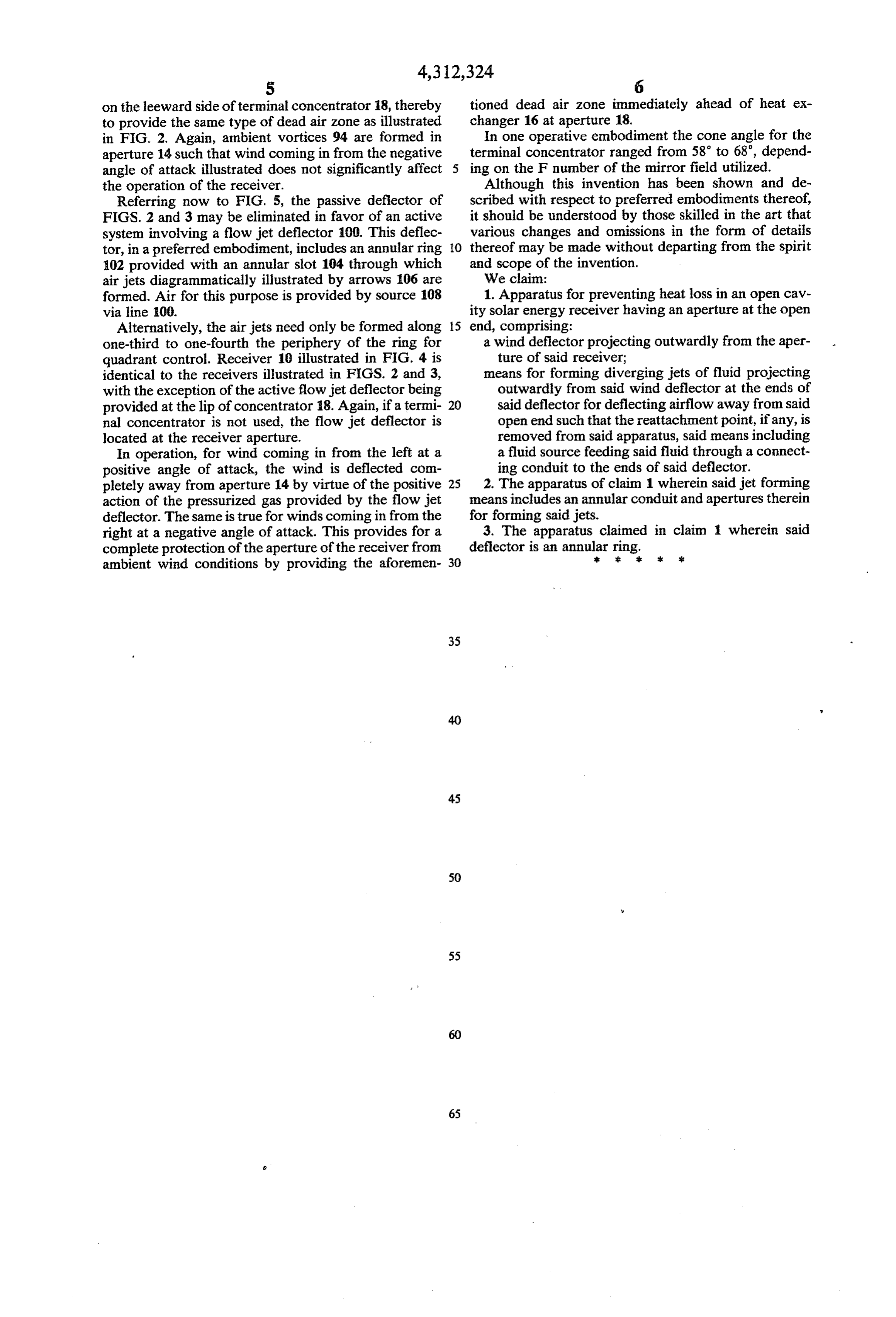
on the leeward side of terminal concentrator 18, thereby tioned dead air zone immediately ahead of heat ex to provide the same type of dead air zone as illustrated changer 16 at aperture 18.
in FIG. 2. Again, ambient vortices 94 are formed in In one operative embodiment the cone angle for the aperture 14 such that wind coming in from the negative terminal concentrator ranged from 58 to 68, depend angle of attack illustrated does not significantly affect ing on the F number of the mirror field utilized. the operation of the receiver. Although this invention has been shown and de Referring now to FIG. 5, the passive deflector of scribed with respect to preferred embodiments thereof, FIGS. 2 and 3 may be eliminated in favor of an active it should be understood by those skilled in the art that system involving a flow jet deflector 100. This deflec various changes and omissions in the form of details tor, in a preferred embodiment, includes an annular ring O thereof may be made without departing from the spirit 102 provided with an annular slot 104 through which and scope of the invention.
air jets diagrammatically illustrated by arrows 106 are We claim:
formed. Air for this purpose is provided by source 108 1. Apparatus for preventing heat loss in an open cav via line 100. ity solar energy receiver having an aperture at the open Alternatively, the air jets need only be formed along 15 end, comprising:
one-third to one-fourth the periphery of the ring for a wind deflector projecting outwardly from the aper quadrant control. Receiver 10 illustrated in FIG. 4 is ture of said receiver;
identical to the receivers illustrated in FIGS. 2 and 3, means for forming diverging jets of fluid projecting with the exception of the active flow jet deflector being outwardly from said wind deflector at the ends of provided at the lip of concentrator 18. Again, if a termi 20 said deflector for deflecting airflow away from said nal concentrator is not used, the flow jet deflector is open end such that the reattachment point, if any, is located at the receiver aperture. removed from said apparatus, said means including In operation, for wind coming in from the left at a a fluid source feeding said fluid through a connect positive angle of attack, the wind is deflected com ing conduit to the ends of said deflector. pletely away from aperture 14 by virtue of the positive 25 2. The apparatus of claim 1 wherein said jet forming action of the pressurized gas provided by the flow jet means includes an annular conduit and apertures therein deflector. The same is true for winds coming in from the for forming said jets.
right at a negative angle of attack. This provides for a 3. The apparatus claimed in claim 1 wherein said complete protection of the aperture of the receiver from deflector is an annular ring.& sk as ambient wind conditions by providing the aforemen 30
Provenance
- Collection
- Cited prior art
- Original PDF
- patentimages.storage.googleapis.com →
- Filed
- 1980-06-16
- Pages
- 7
- Method
- pdftotext (the PDF's own text layer) + pdftoppm 300dpi page scans
- Source
- Google Patents bibliographic record
- Granted
- 1982-01-26
- Inventors
- Don H. Ross; Theodore J. Nussdorfer; Sanders Associates Inc
- Transcribed from
- patentimages.storage.googleapis.com →