patent · US11336224B2
Solar receivers and methods for capturing solar energy
17 May 2022
Page 1 — bibliographic record
United States Patent ( 10) Patent No .: US 11,336,224 B2
( 54 ) SOLAR RECEIVERS AND METHODS FOR ( 56 ) References Cited
CAPTURING SOLAR ENERGY
( 71 ) Applicant: National Technology & Engineering
Solutions of Sandia, LLC , 4,095,997 A * 6/1978 Griffiths HOIL 31/042 Albuquerque, NM ( US ) 136/248
( 72 ) Inventor: Clifford K. Ho , Albuquerque, NM (US ) (Continued ) ( 73 ) Assignee : National Technology & Engineering
Solutions of Sandia, LLC , OTHER PUBLICATIONS
Albuquerque , NM (US )
Santosa et al., “ Investigations into air and refrigerant side heat ( * ) Notice : Subject to any disclaimer, the term of this transfer coefficients of finned - tube CO2 gas coolers,” International patent is extended or adjusted under 35 Journal of Heat and Mass Transfer vol . 107 , Apr. 2017 , pp . 168-180 U.S.C. 154 (b ) by 0 days. ( Year: 2017 ) . * ( 21 ) Appl. No .: 16 /438,604 Primary Examiner Angelo Trivisonno (74 ) Attorney, Agent, or Firm Daniel J. Jenkins
( 65 ) Prior Publication Data ( 57 ) ABSTRACT US 2019/0326852 A1 Oct. 24 , 2019 Thermal receivers, systems , and methods are disclosed that efficiently capture concentrated solar energy into a plurality
Related U.S. Application Data of heat absorption bodies for conversion into thermal energy. ( 62 ) Division of application No. 15 /071,781 , filed on Mar. In an embodiment, the thermal receivers, systems , and 16 , 2016 , now Pat . No. 10,348,241 . methods enable simultaneous electricity conversion and (Continued ) thermal energy capture . The receiver design enables a high penetration of concentrated sunlight deep into the thermal ( 51 ) Int . CI . receiver to increase light trapping and reduce thermal losses . HO2N 6/00 ( 2006.01 ) The thermal receiver is integrated with a photovoltaic (PV) HOIL 31/042 ( 2014.01 ) receiver platform that converts some of the incident light to ( Continued ) electricity while passing the remaining light to the thermal ( 52) U.S. CI. receiver. In another embodiment, other thermal receivers,
systems , and methods are disclosed that efficiently capture (2018.05 ) ; F24S 70/10 (2018.05 ) concentrated solar energy into a sheet of falling particles. In an embodiment, the thermal receivers, systems , and methods ( 58 ) Field of Classification Search enable simultaneous electricity conversion and thermal CPC HO2S 40/44 ; HO2S 40/22; F24S 20/20 ; energy capture.
(Continued ) 10 Claims , 5 Drawing Sheets
1135 D3
Page 2
Related U.S. Application Data ( 60 ) Provisional application No. 62 / 135,547 , filed on Mar.
( 58 ) Field of Classification Search
See application file for complete search history .
2010/0126554 A1 * 5/2010 Morgan HOIL 31/0547
2012/0097216 A1 * 4/2012 Lin F24S 23/00
2014/0366929 A1 * 12/2014 Blau F24S 23/82
2016/0122670 A1 * 5/2016 Klausner BO1J 8/0278
* cited by examiner
Page 3
Drawing sheet — no readable text.
Page 4
Drawing sheet — no readable text.
Page 5
Drawing sheet — no readable text.
Page 6
Drawing sheet — no readable text.
Page 7
Drawing sheet — no readable text.
Page 8
SOLAR RECEIVERS AND METHODS FOR transfer fluid is heated . The heat collected is typically CAPTURING SOLAR ENERGY transferred to rotating machinery , such as a steam turbine, that is used to drive an electric generator. These systems
CROSS - REFERENCE TO RELATED suffer from low efficiencies because of high optical losses , APPLICATIONS 5 such as cosine and other optical losses , solar - receiver losses , as well as temperature and power losses from long fluid - flow
This application is a divisional of U.S. Ser. No. 15/071 , loops to and from the tower . Cosine losses refer to the energy 781 , entitled “ SOLAR RECEIVERS AND METHODS FOR lost when light rays from the sun do not strike the mirror CAPTURING SOLAR ENERGY,” by Clifford K. Ho , filed perpendicular to its surface. To reflect rays of sunlight to the Mar. 16 , 2016 , which claims priority to provisional patent 10 central tower, individual mirrors form an acute angle to the applications U.S. Ser. No. 62/ 135,547 , entitled “ SOLAR sun , therefore requiring more mirror surface than when the RECEIVERS AND METHODS FOR CAPTURING mirror is perpendicular to the sun's rays. Collection effi
SOLAR ENERGY, ” by Clifford K. Ho , filed Mar. 19 , 2015 , ciency is increased and mirror cost is less when the mirror the disclosures of which are incorporated herein by refer- 15 is perpendicular to the sun .
ence in their entireties . Volumetric solar receivers have been developed and implemented in concentrating solar power towers. The
STATEMENT OF GOVERNMENT INTEREST objective is to irradiate a honeycomb or waffle pattern of channels while pulling air through the channels to heat the
The United States Government has rights in this invention air. The air is then used to heat a storage material or to pursuant to Contract No. DE -AC04-94AL85000 between 20 generate steam for electricity production. Current designs of the United States Department of Energy and Sandia Corpo- the channels do not allow for deep penetration of the ration , for the operation of the Sandia National Laboratories, irradiance, and the receiver surfaces get hot near the aper and to Contract No. DE -NA0003525 awarded by the United ture, maximizing radiative heat loss . None of the previous States Department of Energy /National Nuclear Security 25 volumetric receiver designs integrates PV . Administration . Solar receivers have also been used to heat particles, both inert and thermochemically reactive particles for additional
TECHNICAL FIELD energy storage . Although no commercial solid particle receivers exist , a significant amount of research has been
The present disclosure is generally directed to solar performed to develop efficient solid particle receivers for energy. The present disclosure is more particularly directed 30 energy storage and electricity production. None of these to solar thermal systems that integrate a photovoltaic system previous concepts has included the use of aa light-transmit with a thermal receiver. ting PV array at the aperture to generate electricity while mitigating convective and radiative heat losses .
BACKGROUND The need remains , therefore, for a solar thermal system 35 that efficiently converts sunlight into heat. The need also
Solar power systems offer much promise for clean energy , remains for solar power systems that combine the efficien with few , or zero , carbon emissions. These systems collect cies of solar thermal systems and PV systems . The need also incident sunlight and convert this sunlight into aa usable form remains for solar power systems that combine the efficien of power, such as heat or electricity. Solar energy offers a cies of thermochemical particle systems and PV systems. clean , inexhaustible, sustainable solution to energy demands 40 and has the potential to supply a very significant fraction of SUMMARY OF THE DISCLOSURE U.S. and global electricity consumption. While the U.S. and global solar power potential is known to be immense, solar In an embodiment of the disclosure, a solar receiver is power systems have not been economically competitive disclosed that includes a thermal receiver and a photovoltaic without government support, to date. Challenges remain to 45 receiver attached to the thermal receiver. The thermal devise solar technologies that can lower installation costs , receiver includes a housing having an opening for receiving increase power output, and lower the marginal cost per unit concentrated solar energy and a plurality of heat absorbing energy produced, for a lower levelized cost of energy. An bodies defining a passageway. The passageway includes an important metric is the overall system efficiency, that is , the opening and an exit opening. The photovoltaic receiver electric power output per incident solar power collected . 50 includes openings for allowing air to pass through the Solar power systems include photovoltaic (PV) systems, photovoltaic receiver to the opening of the passageway of solar thermal systems, and others . PV systems utilize pho- the thermal receiver. The photovoltaic receiver is configured tovoltaic solar cells that convert sunlight directly into elec- to allow concentrated solar light passing through the pho tricity by the photovoltaic effect. These solar cells are tovoltaic receiver to illuminate the plurality of heat absorb expensive, and their efficiencies are limited because they can 55 ing bodies exploit only a portion of the solar spectrum . These systems In another embodiment of the disclosure , a method of are also characterized by a large energy -payback period, i.e. , capturing concentrated solar energy is disclosed that the time they must be exposed to sunlight and produce includes illuminating a photovoltaic receiver with concen electricity, to return the energy required to produce and trated solar energy, capturing a portion of the concentrated install them . 60 solar energy with the photovoltaic receiver to generate Solar thermal systems convert sunlight into heat and electricity, absorbing a portion of the concentrated solar either use this heat directly or convert the heat to generate energy passing through the photovoltaic receiver into a electricity. Examples of solar thermal systems include solar plurality of heat absorbing bodies, and heating air passing power towers, parabolic trough systems, and dish -Stirling over the plurality of heat absorbing bodies . systems . Solar power towers utilize a large number of 65 In another embodiment of the disclosure, a thermal steerable , planar, or near-planar mirrors that reflect and receiver system is disclosed that includes a housing having direct rays of sunlight to a central tower where a heat- an opening for receiving concentrated solar energy, and a
Page 9
plurality of heat absorbing bodies defining a passageway Light passing through the PV receiver heats particles pass within the housing . The passageway comprising an opening ing through the falling particle receiver. for receiving air and an exit opening for discharging heated In an embodiment of the disclosure, a method for cap air. Concentrated solar energy received in the opening of the 5 turing solar energy is disclosed that includes capturing a housing is directed into the opening of the passageway . portion of the solar energy by a PV array, and allowing In another embodiment of the disclosure, a method of another portion of the solar energy to pass through the PV capturing solar energy is disclosed that includes passing array to be captured by a solar thermal receiver. concentrated solar energy through a window , absorbing a In an embodiment of the disclosure, a method for cap portion of the concentrated solar energy passing through the turing solar energy is disclosed that includes capturing a photovoltaic receiver into a plurality of heat absorbing 10 portion of the solar energy by a PV array, and allowing bodies, and heating air by contacting the air with the another portion of the solar energy to pass through the PV plurality of heat absorbing bodies. array to heat particles.
In another embodiment of the disclosure , a solar receiver An advantage of the present disclosure is to provide a is disclosed that includes a falling particle receiver and a solar power system that combines solar thermal and PV photovoltaic receiver attached to the falling particle receiver. 15 systems .
The photovoltaic receiver captures a portion of the solar Another advantage of the present disclosure is that the spectrum for conversion to electricity while being transmis- integration of a volumetric air receiver and a PV system sive to another portion of the solar spectrum that is absorbed enables cooling of the PV system for higher efficiency by particles falling through the falling particle receiver. operation and preheating of the air before it enters the In another embodiment of the disclosure, a method for 20 volumetric receiver. Another advantage of the present dis capturing solar energy is disclosed that includes illuminating closure is the radial design of the volumetric receiver a photovoltaic receiver with concentrated solar energy, cap- surfaces that allows a greater penetration of the solar irra turing a portion of the concentrated solar energy with the diance, reducing the radiative heat loss near the aperture . photovoltaic receiver to generate electricity, and absorbing a An advantage of integrating a PV array at the aperture portion of the concentrated solar energy passing through the 25 ( and along the spillage boards surrounding the aperture) of photovoltaic receiver into a plurality falling particles passing a falling particle receiver system is that electricity and through a thermal receiver. thermal energy can be simultaneously generated. The PV In another embodiment of the disclosure , a thermal array can have holes or slots to enable a small amount of receiver system is disclosed that includes a falling particle ambient air flow into and out of the receiver to keep the PV thermal receiver comprising an opening for receiving con- 30 array cooler for improved efficiency. The PV array will also centrated solar energy , and one or more heliostats for minimize convective and radiative heat losses from within directing concentrated solar energy into the opening. The the cavity receiver.
falling particle thermal receiver is configured flow par Other features and advantages of the present disclosure ticles in a sheet having a thickness of between having a will be apparent from the following more detailed descrip thickness between 0.5 cm and 5 cm . 35 tion of the preferred embodiment, taken in conjunction with In another embodiment of the disclosure, a method of the accompanying drawings which illustrate, by way of capturing solar energy is disclosed that includes directing example , the principles of the disclosure . concentrated solar energy into an opening of a falling particle solar receiver, and heating a falling sheet of particles BRIEF DESCRIPTION OF THE DRAWINGS with the concentrated solar energy passing though the open- 40 ing . FIG . 1 is an illustration of a cut away view of a thermal In another embodiment of the disclosure , a solar receiver receiver according to an embodiment of the disclosure . is disclosed that includes a thermal receiver and a PV FIG . 1A is an illustration of a fin according to an embodi receiver attached to the thermal receiver. The PV receiver ment of the disclosure .
includes openings for allowing light to pass through the PV 45 FIG . 1B is an illustration of a thermal receiver system receiver to the thermal receiver, and the PV receiver is according to an embodiment of the disclosure . cooled by air flowing to the thermal receiver. FIG . 2 is an illustration of a cut away view of another In an embodiment of the disclosure, a solar receiver is embodiment of a thermal receiver according to an embodi disclosed that includes a falling particle receiver and a PV ment of the disclosure .
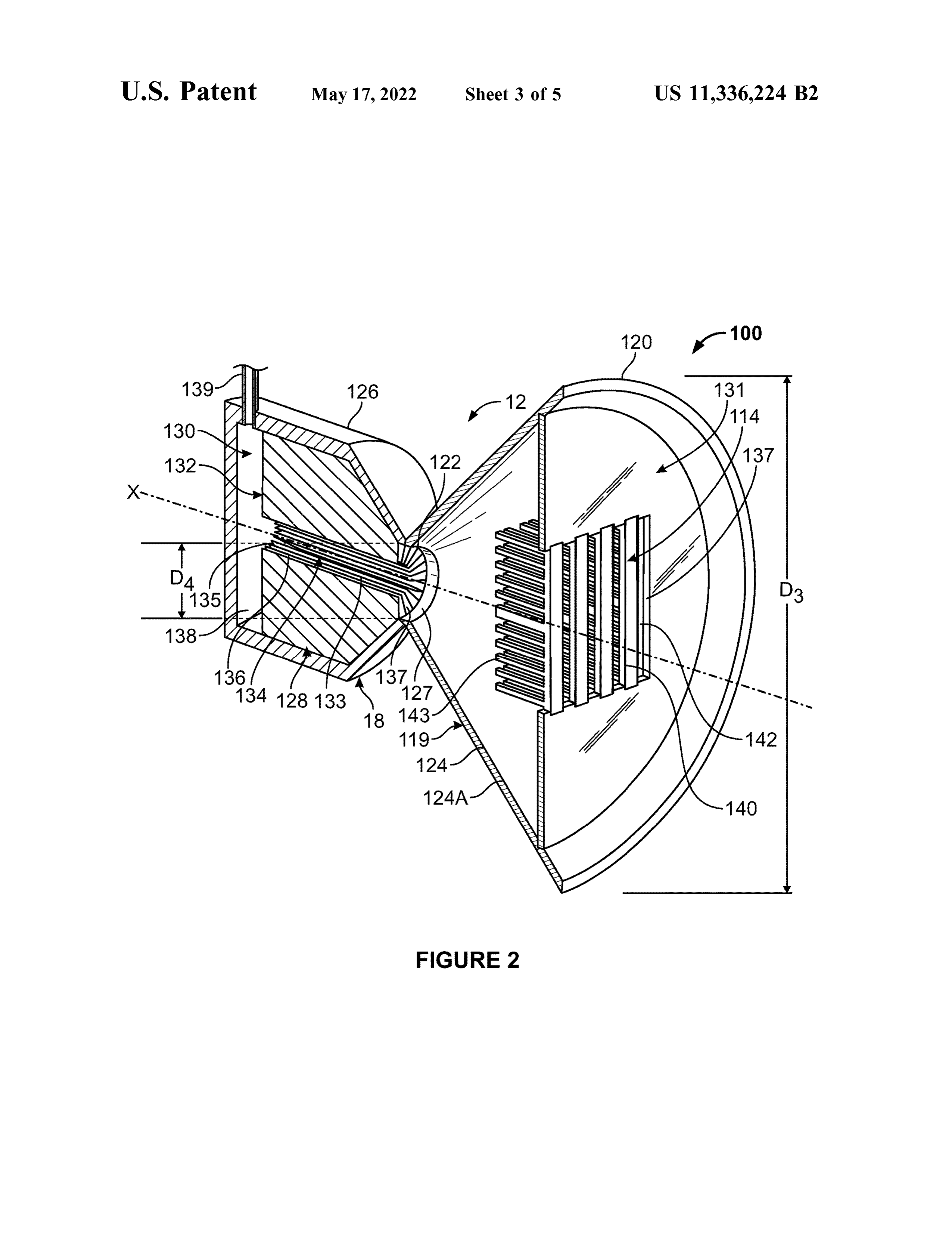
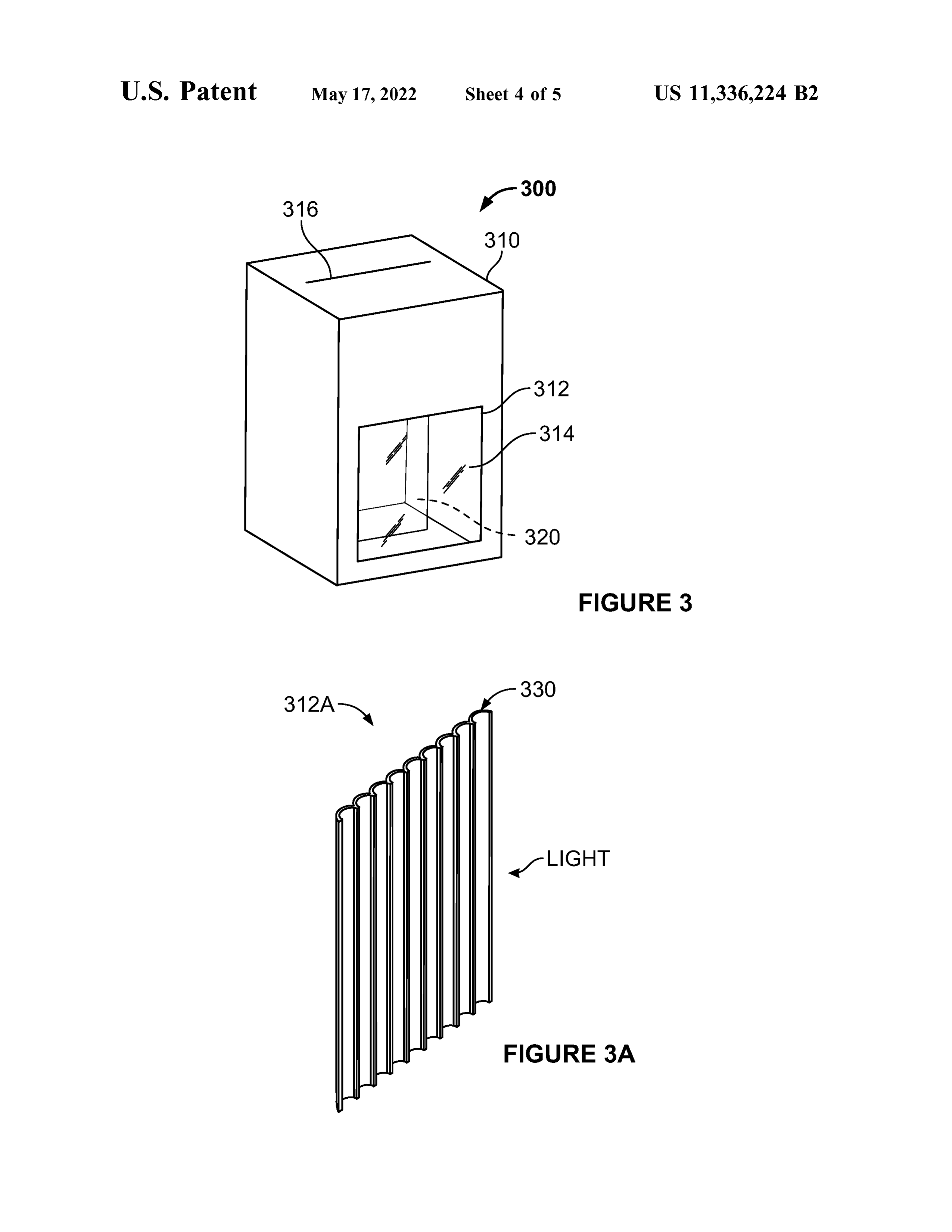
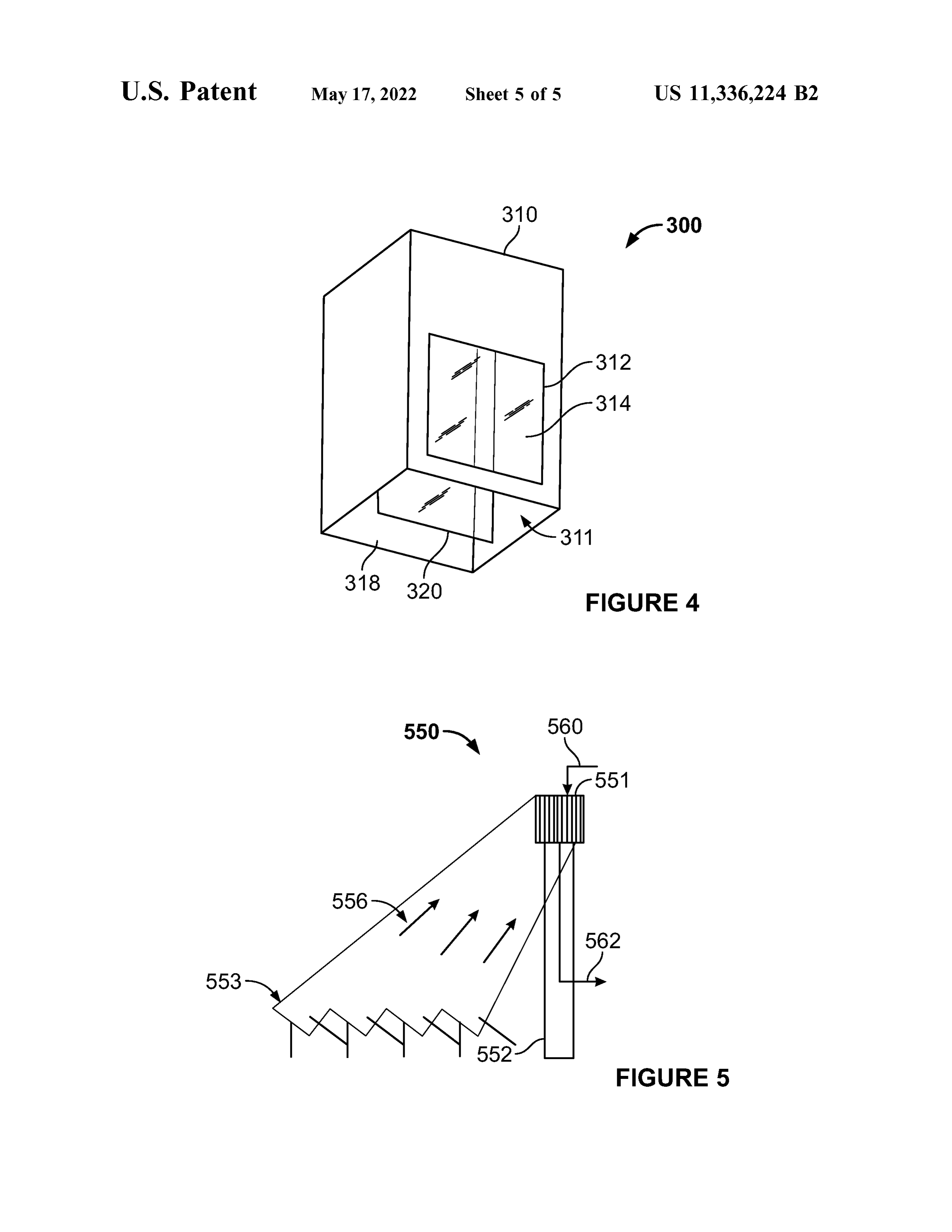
receiver attached to the falling particle receiver. Light pass- 50 FIG . 3 is an illustration of a falling particle receiver ing through the PV receiver heats particles passing through according to an embodiment of the disclosure . the falling particle receiver. FIG . 3A is an illustration of a high temperature window In an embodiment of the disclosure, a solar collection according to an embodiment of the disclosure . system is disclosed that includes a concentrating solar FIG . 4 is another view of the falling particle receiver of collection system and aa solar receiver for receiving concen- 55 FIG . 3 .
trated solar energy from the concentrating solar collection FIG . 5 is an illustration of another thermal receiver system system . The solar receiver includes aa thermal receiver and a according to another embodiment of the disclosure . PV receiver attached to the thermal receiver. The PV Wherever possible , the same reference numbers will be receiver includes openings for allowing light to pass through used throughout the drawings to represent the same parts . the PV receiver to the thermal receiver, and the PV receiver 60 is cooled by air flowing to the thermal receiver. DETAILED DESCRIPTION In an embodiment of the disclosure , a solar collection system is disclosed that includes a concentrating solar The present invention now will be described more fully collection system and aa solar receiver for receiving concen- hereinafter with reference to the accompanying drawings, in trated solar energy from the concentrating solar collection 65 which preferred embodiments of the invention are shown . system . The solar receiver includes a falling particle receiver This invention may, however, be embodied in many different and a PV receiver attached to the falling particle receiver. forms and should not be construed as limited to the embodi
Page 10
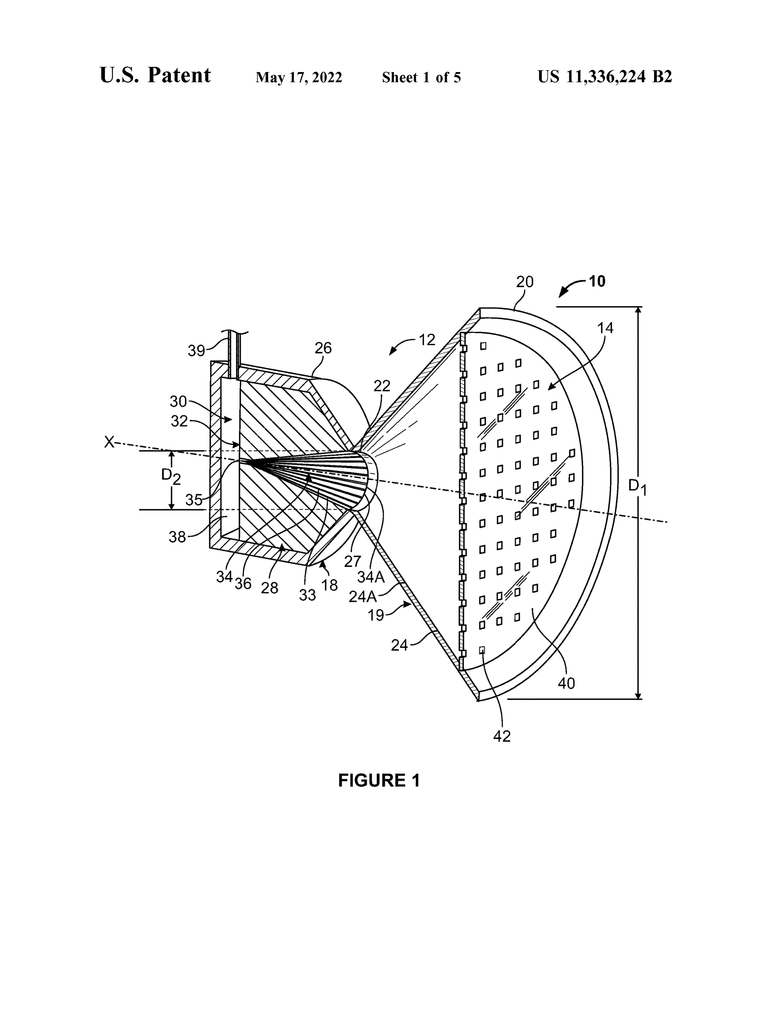
ments set forth herein ; rather, these embodiments are pro- In this exemplary embodiment, the solar collector unit 19 vided so that this disclosure will be thorough and complete includes an optional PV panel or receiver 14. The PV and will fully convey the scope of the invention to those receiver 14 includes aa PV cell or array 40 disposed upon the skilled in the art . PV receiver 14. In this exemplary embodiment, the PV array The present disclosure is directed to a thermal receiver 5 40 covers the surface of the PV receiver 14. In other embodiments, the PV receiver may include one or more PV that includes a plurality of thermal panels for capturing solar arrays energy from concentrated sunlight and transferring the cap 40 that may cover all or a portion of the surface of the tured energy to air. A light focusing device focusses and PV receiver or be otherwise integrated into the PV receiver concentrates light on the thermal receiver to capture heat. 14. In other embodiments , the PV receiver 14 may be Air is pulled through the thermal receiver and heat is 10 omitted . The PV receiver 14 is a transmissive, semiconduc transferred from the thermal receiver to the air to generate tor structure that allows thermal spectrum to pass through heated air . The heated air can be used for other applications, while capturing other portions of the solar spectrum for such as , but not limited to in a heat exchanger for thermal of light that topasses conversion electricity. In an embodiment, the percentage through the PV receiver 14 to the thermal storage ( e.g. , in solid media , particles, or molten salt ) or 15 receiver can vary between 10 % -90 % depending on the need electricity generation (e.g. , generate steam for Rankine and value for thermal storage . In this exemplary embodi power cycle ). ment, the PV receiver 14 is shown conforming to the In an embodiment, the light focusing device may be a housing 24. In other embodiments, the PV receiver 14 may mirror or array of mirrors. In an embodiment, the thermal or be separated from or partially separated the housing 24 to solar receiver is disposed on top of a tower surrounded by a 20 allow air to pass between the PV receiver 14 and the housing field of heliostats . In another embodiment, the light focusing 24 .
device may include a dish collector system , where the The PV receiver 14 includes a plurality of openings 42 thermal or solar receiver are attached to a truss and located that allow for concentrated light and pass through and be near the focal point of the dish . In an embodiment, the dish absorbed the heat exchange unit 18 thereby heating the collector tracks the sun during normal operation. 25 thermal receiver 12. Note that this light is in addition to the In an embodiment the thermal receiver may include aa PV light passing through the PV receiver 14. The openings 42 array to generate electricity. The PV array is disposed in the also allows for air to pass through and cool the PV receiver light focusing device. The PV array includes gaps or opening 14 , increasing the efficiency thereof. In this exemplary so that light can transmit through to the thermal receiver ( the embodiment, the openings are square, however, in other cells themselves can also be transmissive at particular wave- 30 embodiments, the openings 42 may be , but are not limited to lengths ) to generate heat . The air pulled through the thermal circular, oval , square, and rectangular shapes . receiver also serves to cool the PV array so that it can The PV receiver 14 includes electrical leads , conductors , operate more efficiently lower temperatures. connections and other elements (not shown) that collect The present disclosure is also directed to methods for electrical energy from the PV receiver 14. These compo capturing solar energy that includes capturing solar thermal 35 nents are not shown for simplicity however, the structure and energy and transferring that energy to air. In an embodiment, function thereof are well understood in the art . In another the method also includes the generation of electrical energy. embodiment, the PV receiver 14 may have fins or other heat The present disclosure is further directed to solar receiv- exchange members extending from the rear side of the PV ers and methods for capturing solar energy using a solar array 40 to improve cooling of the PV array . receiver having a veil , curtain or sheet of falling particles 40 In other embodiments , the solar collector unit 19 may that absorb the solar energy. include a high temperature window similar in shape and in FIG . 1 shows aa cross -section of an embodiment of thermal place of the PV receiver 14. The high temperature window receiver 10 according to an embodiment of the disclosure . may be made of a high temperature, solar transmissive The thermal receiver 10 includes a heat exchange unit 18 material, such as , but not limited to quartz . When the thermal and a solar collector unit 19. The solar collector unit 19 , 45 receiver 10 includes the PV receiver 14 , the thermal receiver which may be referred to as a secondary concentrator, 10 may be referred to as a solar receiver. The combination includes a housing 24 having a conical geometry having a of the thermal receiver 10 and PV receiver 14 allows the first end 20 having a first diameter D1 that tappers to a solar receiver to utilize the full spectrum of solar irradiance second end 22 having a second diameter D2 , where D1 >D2 . to generate electricity and heat .
The housing 24 includes an inner surface 24A that directs or 50 The heat exchange unit 18 includes a housing 26. The channels concentrated sunlight towards the second end 22 . housing 26 includes an opening 27 that corresponds to the The inner surface 24A that may be any reflective surface to second end 22 of the solar collector unit 19. The opening 27 direct the light toward the aperture of the thermal receiver. is positioned so as to also be or is proximate to the focal In such a manner, the shape of the solar receiver 10 exploits plane for concentrated sunlight that has been focused upon the converging/ diverging rays from aa dish collector or other 55 the thermal receiver 10 .
solar concentrator. The inner surface 24A is cooled by the The heat exchange unit 18 further includes aa heat absorb incoming air flow . In this exemplary embodiment, the solar ing unit 28 and heat transfer zone 30 disposed within the collector unit 19 has a conical geometry, however, in other housing 26. The heat absorbing unit 28 includes a plurality embodiments, the solar collector unit 19 may have aa conical , of radially extending heat absorbing bodies or fins 32 parabolic, or other geometry that focusses and / or concen- 60 disposed around passageway 34. The fins 32 have inner or trates solar energy into the opening 27 . passageway surfaces 33 that define passageway 34. The fins In another embodiment, the solar collector unit 19 may be 32 also define radial spaces 36 between adjacent fins 32. The omitted . In an embodiment where the solar collector unit 19 passageway 34 and the radial spaces 36 enable air to flow is omitted , a high temperature window (not shown) may be between the opening 27 and the collection space 38 while in placed over the opening 27. The high temperature window 65 contact with the fins 3 , enabling heat to be transferred to the
is formed of a high temperature, solar spectrum transmissive air from the fins. Heat is also transferred to the air from the material, such as , but not limited to quartz . fins 32 while the air is in the collection space 38 .
Page 11
The fins 32 are formed of a high temperature material system via the outlet 39 that utilizes the heated air for a such as metal , ceramic and cermet. In an embodiment, the secondary purpose. In another embodiment, a fan or other fins 32 may be formed of a metal, such as , but not limited air moving device or system may be connected to the outlet to stainless steel , Inconel 625 , or Haynes 230 The fins 32 39 to assist the flow of air through the thermal receiver 10 . may have surfaces or coatings on the fin surfaces 33 and / or 5 The heated air may be used in a secondary system , such as, surfaces facing adjoining fins that have features or perfora tion to enhance the penetration and / or trapping of light and but not limited to systems to heat thermochemically reactive particles, drive power generation equipment, heat secondary to enhance the heat transfer to the flow air. The fins 32 are fluids, heat particles from a falling particle receiver, or heat oriented to allow deep penetration of the light rays for any other working fluid for thermal or electrical power volumetric heat absorption while minimizing re -radiation 10 generation .
( thermal emittance ) out of opening 27 , and in particular back In an embodiment , the thermal receiver 10 can translate to the PV receiver 14 .
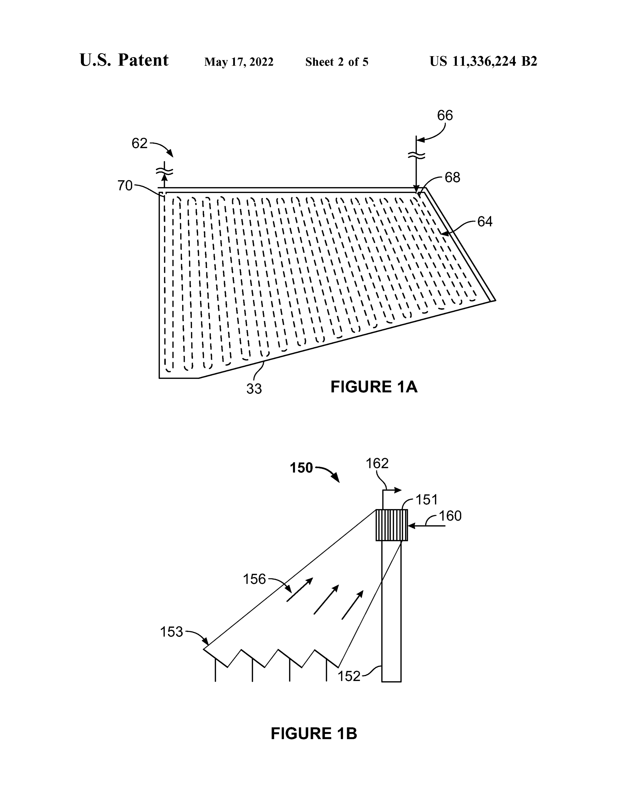
FIG . 1 A illustrates an embodiment of a fin 62 according a along the axis of the collector focal length X to allow to an embodiment of the disclosure . In this exemplary variable power to reach the thermal receiver 12 and PV embodiment, the fin 62 includes an internal channel or 15 receiver 14. This may be important when the direct normal micro -channel 64 in fluid connectivity with a secondary irradiance (DNI ) is changing and / or when more or less fluid system 66 for the heating of a secondary fluid, such as , thermal capture and / or storage is desired relative to PV but not limited to gases , liquids, and supercritical fluids . The power generation. For example, during off-peak, low - load micro -channel 64 has an input 68 and output 70 for receiving times , it may be more desirable to generate thermal energy and outputting a fluid from the micro - channel 64. In other 20 for storage rather than electricity. Then , the PV receiver 12 embodiments , the fin 62 may have one or more channels or would be moved further away from the thermal receiver 12 micro - channels. In this exemplary embodiment, the input 68 (and focal plane ) so that more of the concentrated solar flux is shown providing fluid to a portion of the fin 62 closest to can reach the thermal receiver 10. In an embodiment, the the opening 27. For example, the secondary fluid may be a thermal receiver 10 is a component of a solar collection gas such as , but not limited to helium ; a liquid such as , but 25 system that includes a mirror or array of mirrors to focus and not limited to water, liquid metals , molten salts , hydrocar concentrate sunlight onto the receiver. bons ; and supercritical fluids such as , but not limited to FIG . 1B illustrates aa thermal receiver system ( system) 150 supercritical CO2*. In another embodiment, the fin 62 may according to an embodiment of the disclosure . As can be include one or more cavities for containing a secondary seen in FIG . 1A , the system 150 includes aa thermal receiver fluid . 30
The heat transfer zone 30 includes open space or airways receives151 mounted atop a tower 152. The thermal receiver 151 in contact with the fins 32 and includes passageway 34 , system also ambient air 160 and produces heated air 162. The radial spaces 36 between the fins 32 , and a collection space solar light 156includes heliostats 153 that direct concentrated 38. In this exemplary embodiment, the passageway 34 has a embodiment, four heliostats receiver at the thermal are 151. In this exemplary shown , however , in other conical geometry. In another embodiment, the passageway 35 embodiments, the system 150 may include one or more 34 may have other geometries, such as , but not limited to heliostats . The
thermal receiver 151 may be the receiver cylindrical or tubular with a circular, square , hexagonal or other cross - section . The passageway 34 includes opening may shown in FIG . 1 and described above . Other embodiments 34a that is fluidly connected to opening 27. In this exem include the thermal receiver shown in FIG . 2 and plary embodiment, the opening 34a smoothly transitions to 40 described below .
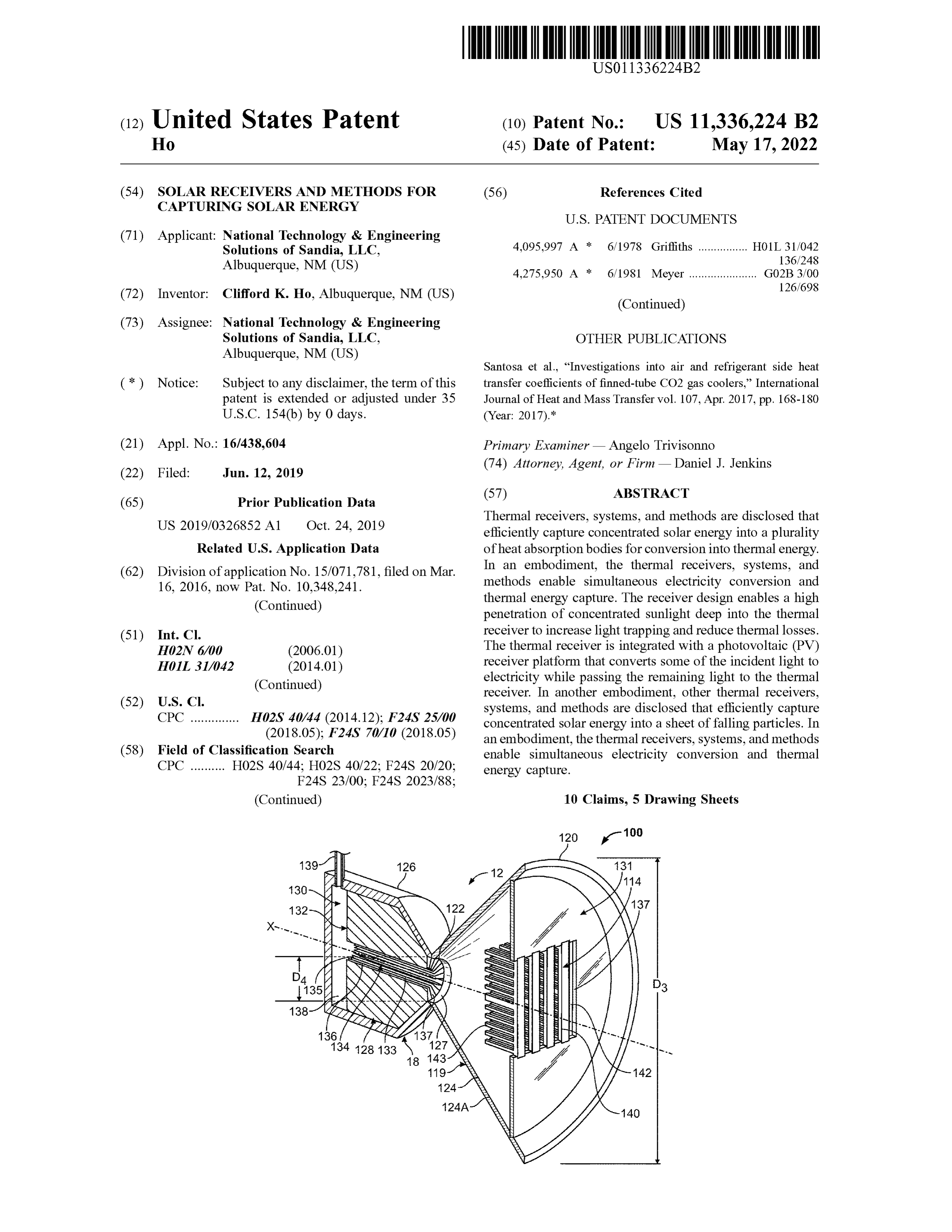
opening 27 of housing 26 so as to allow light entering FIG . 2 illustrates an embodiment of a solar receiver 100 opening 27 to be unobstructed in penetrating into passage- according to the present disclosure . The solar receiver 100 way 34. The passageway also includes exit opening 35. The includes a thermal receiver 112 and a PV receiver 114. The passageway 34 is defined by fin surfaces 33 of fins 32. The thermal receiver 112 includes a heat exchange unit 118 and conical geometry of the passageway 34 provides a light- 45 a solar collector unit 119. The solar collector unit 119 , which trapping geometry with low radiative view factors and may be referred to as a secondary concentrator, has a thermal emittance back to the collector support panel 14 and housing 124 having a conical geometry having a first end to the environment. 120 having a first diameter D3 that tappers to a second end As discussed above , the passageway 34 receives air from 122 having a second diameter D4 , where D3 >D4 . The the opening 27 and allows for that air to either flow into the 50 housing 124 includes an inner surface 124A that directs or radial spaces 36 between the fins 32 or to flow though the channels concentrated sunlight towards the second end 122 . passageway 34 and into the collection space 38 via an exit The inner surface 124A may be any reflective surface to opening 35. The radial spaces 36 are also open to the direct the light toward the aperture of the thermal receiver. collection space 38 so as to allow the air flowing in the radial The inner surface 124A will be cooled by the incoming air spaces 36 to flow into the collection space 38. The air 55 flow . In another embodiment, the solar collector unit 119 flowing through the passageway 34 and is heated by the fin may have a conical, parabolic, or other geometry that surfaces 33. The passageway 34 allows for focused sunlight focusses and / or concentrates solar energy into the opening passing through the opening 27 to be absorbed by the fin 127 .
surfaces 33 as the sunlight diverges and travels down the In another embodiment, the solar collector unit 119 may conical passageway 34 . 60 be omitted . In an embodiment where the solar collector unit Also as discussed above, the collection space 38 is a 119 is omitted , a high temperature window ( not shown) may volume that receives air from the passageway 34 and radial be placed over the opening 127. The high temperature spaces 36. The collection space 38 is fluidly connected to an window is formed of a high temperature, solar spectrum outlet 39 that allows air to exit the collection space 38. In transmissive material, such as , but not limited to quartz . such a manner , air is drawn into the opening 27 , heated by 65 The heat exchange unit 118 includes a housing 126. The fins 32 that have been heated by concentrated sunlight, housing 126 includes an opening 127 that corresponds to the collected in the collection space 38 and provided to another second end 122 of the solar collector unit 119. The opening
Page 12
127 is positioned so as to also be or is proximate to the focal In another embodiment, the fins 132 may include chan
plane for concentrated sunlight that has been focused upon nels or micro - channels in fluid connectivity with secondary the solar receiver 100 . systems for the heating of a secondary fluid, such as , but not The heat exchange unit 118 further includes a heat absorb- limited to gases , liquids, and supercritical fluids. For ing unit 128 and heat transfer zone 130 disposed within the 5 example , the secondary fluid may be a gas such as , but not limited to helium ; a liquid such as , but not limited to water, housing 124. The heat transfer zone 130 includes open space liquid or airways in contact with the fins 132 and includes a metals , molten salts , hydrocarbons; and supercritical passageway 134 , radial spaces 136 and a collection space fluids such as , but not limited to supercritical CO2 . 138. In this exemplary embodiment, the passageway 134 has As discussed above, the solar collector unit 119 concen a cylindrical geometry. In another embodiment, the passage 10 trates sunlight into the opening 127. In this exemplary way 34 may have another geometry, such as , but not limited strate or cap ,131 embodiment the solar collection unit includes an end sub to conical . In this exemplary embodiment, the passageway 131 has a central supported opening by the housing 124. The end cap 137. In an embodiment, all or part 134 has a circular cross - section , however, in other embodi of the end cap 131 may be translucent or allow for the ments the cross - section may be, but is not limited to circular, 15 transmittance of light. In an embodiment, the end cap 131 square , and hexagonal . The passageway 134 is fluidly con may have one or more PV arrays integrated with or attached nected to opening 127 and includes exit opening 135. The to the end cap 131. In another embodiment, the end cap 131 passageway 134 is defined by fin surfaces 133 of fins 132 . may have one or more openings. The PV receiver 114 is The cylindrical geometry of the passageway 134 provides a supported by the end cap 131 in the central opening. light - trapping geometry with low radiative view factors and 20 The PV receiver 114 includes a PV cell or array 140 thermal emittance back to the PV receiver 114 and to the disposed upon the surface of the PV receiver 114. In other environment. embodiments, the PV receiver 114 may include one or more The passageway 134 receives air from the opening 127 PV arrays 140 that may cover all or a portion of the surface and allows for that air to either flow into the radial spaces of the PV receiver 114. Electrical connections to and from 136 between the fins 132 or to flow though the passageway 25 the PV receiver 114 are not shown for clarity, however, the 134 and into the collection space 138 via an exit opening structure and function thereof are well understood in the art . 135. The radial spaces 136 are also open (not shown) to the The PV receiver 114 allows for at least a portion of light collection space 138 so as to allow the air flowing in the incident to the PV array to pass through the PV receiver 114 radial spaces 136 to flow into the collection space 138. The and thus be collected and used for thermal heating in the air flowing through the passageway 134 is heated by the fin 30 thermal receiver 112. In an embodiment, the percentage of surfaces 133. The passageway 34 allows for focused sun- light that passes through the PV array to the thermal receiver light passing through the opening 127 to be absorbed by the can vary between 10 % -90 % depending on the need and fin surfaces 133 as the sunlight diverges and travels down value for thermal storage.
the conical passageway 134 . The PV receiver 114 includes openings 142. The openings The heat absorbing unit 128 includes a plurality of 35 142 allow for concentrated light and air to pass through the radially extending bodies or fins 132 disposed around pas- PV array 140 and be collected and used for thermal heating sageway 134. As discussed above, the fins 132 have fin in the thermal receiver 112. In this exemplary embodiment, surfaces 133 and radial spaces 136 between adjoining fins the openings 142 are slots and have a rectangular cross that allow for the passage of air from the passageway 134 to section , however, in another embodiment, the openings 42 the collection space 138. The fins 132 are formed of aa high 40 may be of any suitable geometry, such as , but not limited to temperature material such as metal , ceramic and cermet. In circular, square, oval , and rectangular. The air passing an embodiment, the fins 132 may be formed of a metal, such through the openings 142 of the PV receiver 112 cool the PV as , but not limited to stainless steel , Inconel 625 , or Haynes array, increasing efficiency thereof. In this exemplary
230. The fins 132 may have surfaces or coatings on the fin embodiment, the PV receiver 114 includes heat transfer surfaces 133 and / or surfaces facing adjoining fins that have 45 members 143 that extend from the PV receiver towards the features or perforation to enhance the penetration and / or opening 127 that cool the PV receiver 114 by transferring trapping of light and to enhance the heat transfer of the flow heat from the PV receiver 114 to air passing through the air. The fins 132 are oriented to allow deep penetration of the solar collection unit 19 to the thermal receiver 112 . light rays for volumetric heat absorption while minimizing In an embodiment, the thermal receiver 112 and PV re - radiation (thermal emittance) out of opening 127 , and in 50 receiver 114 can translate along the axis of the collector particular back to the PV receiver 114. In this exemplary focal length X to allow variable power to reach the thermal embodiment the fins 132 include a leading edge 137. In an receiver 112 and PV receiver 114. This may be important embodiment, the leading edge may be light absorbing and / or when the direct normal irradiance ( DNI ) is changing and / or include a light absorbing coating. In another embodiment, when more or less thermal capture and / or storage is desired the leading edge may be omitted and the surface 133 may 55 relative to PV power generation. For example , during off taper to the opening 127. In such a manner , the shape of the peak , low - load times , it may be more desirable to generate heat absorbing units exploits the converging /diverging rays thermal energy for storage rather than electricity . Then, the from a dish collector or other solar concentrator. PV receiver 112 would be moved further away from the As discussed above , the collection space 138 is a volume thermal receiver 112 ( and focal plane) so that more of the that receives air from the passageway 134 and radial spaces 60 concentrated solar flux can reach the thermal receiver 112 . 136. The collection space 138 is fluidly connected to an FIGS . 3 and 4 illustrate an embodiment of a solar receiver outlet 139 that allows air to exit the collection space 138. In 300 according to another embodiment of the disclosure . The such a manner , air is drawn into the opening 127 , heated by solar receiver 300 includes a housing 310 having a window fins 132 that have been heated by concentrated sunlight, 312. The housing 310 surrounds an interior space or cavity collected in the collection space 138 and provided to another 65 311. The window 312 allows for concentrated sunlight to system via the outlet 139 that utilizes the heated air for a enter the cavity 311. In this exemplary embodiment, the secondary purpose. window 312 includes aa PV cell or array 314 disposed upon
Page 13
the surface thereof. In another embodiment, the window 312 mitigate convective and radiative heat loss from within the may include one or more PV cells and / or arrays. The PV cavity 311. Also , the air movement within the cavity 311 array 314 is a transmissive, semiconductor structure that from the falling particles and air passing through the PV allows thermal spectrum to pass through while capturing array 314 can serve to cool the PV array . The ambient air that other portions of the solar spectrum for conversion to 5 enters the cavity 311 may also leave the cavity 311 through electricity. In an embodiment, the percentage of light pass- the openings in the PV array or become entrained with the ing through the PV array 314 can vary between 10 % -90 % particles . In other embodiments , air may also be deliberately depending on the need and value of the remaining light blown along the window or PV array to cool the window or spectrum passing through the PV array 314 . PV array
In another embodiment the window 312 may not include 10 Particles heated in the portion of the cavity 311 that the a PV array 314 , and may be formed of a high temperature , particles pass through or particle heating zone 318 may be solar spectrum transmissive material, such as , but not lim used ited to quartz. aIn this exemplary embodiment, the window ticles for may thermochemical processes . For example, the par be reduced and absorb extra energy beyond the 312 may have a flat front facing surface as shown in FIGS .
3 and 4. In another embodiment,the front facing surface of 15 the sensible heating energy required to raise the temperature of the window 312 may be not be flat, but may be undulating, air particle . The particles could then be later oxidized by an stream to recoup the sensible and thermochemically wavy or of other light trapping or guiding geometries, which may reduce the reflective losses relative to a flat window . stored energy
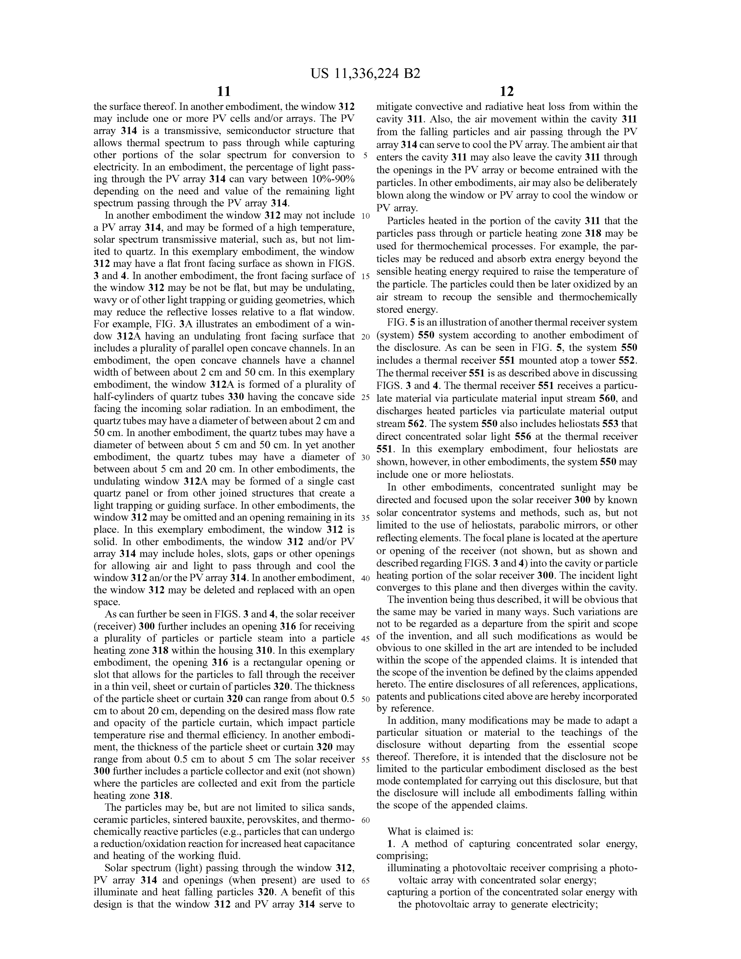
For example, FIG . 3A illustrates an embodiment of aa win FIG . 5 is an illustration of another thermal receiver system dow 312A having an undulating front facing surface that 20 ( system ) 550 system according to another embodiment of includes a plurality of parallel open concave channels. In an the disclosure . As can be seen in FIG . 5 , the system 550 embodiment, the open concave channels have a channel includes a thermal receiver 551 mounted atop a tower 552 . width of between about 2 cm and 50 cm . In this exemplary The thermal receiver 551 is as described above in discussing embodiment, the window 312A is formed of a plurality of FIGS . 3 and 4. The thermal receiver 551 receives a particu half - cylinders of quartz tubes 330 having the concave side 25 late material via particulate material input stream 560 , and facing the incoming solar radiation . In an embodiment, the discharges heated particles via particulate material output quartz tubes may have a diameter of between about 2 cm and stream 562. The system 550 also includes heliostats 553 that 50 cm . In another embodiment, the quartz tubes may have a direct concentrated solar light 556 at the thermal receiver diameter of between about 5 cm and 50 cm . In yet another 551. In this exemplary embodiment, four heliostats are embodiment, the quartz tubes may have a diameter of 30 shown, however, in other embodiments, the system 550 may between about 5 cm and 20 cm . In other embodiments, the include one or more heliostats. undulating window 312A may be formed of a single cast In other embodiments, concentrated sunlight may be quartz panel or from other joined structures that reate a directed and focused upon the solar receiver 300 by known light trapping or guiding surface . In other embodiments, the solar concentrator systems and methods, such as , but not window 312 may be omitted and an opening remaining in its 35 place . In this exemplary embodiment , the window 312 is limited to the use of heliostats, parabolic mirrors, or other solid . In other embodiments, the window 312 and / or PV reflecting elements. The focal plane is located at the aperture array 314 may include holes, slots , gaps or other openings or opening of the receiver (not shown , but as shown and for allowing air and light to pass through and cool the described regarding FIGS . 3 and 4 ) into the cavity or particle window 312 an / or the PV array 314. In another embodiment , 40 heating portion of the solar receiver 300. The incident light the window 312 may be deleted and replaced with an open converges to this plane and then diverges within the cavity. space . The invention being thus described , it will be obvious that As can further be seen in FIGS . 3 and 4 , the solar receiver the same may be varied in many ways . Such variations are ( receiver) 300 further includes an opening 316 for receiving not to be regarded as a departure from the spirit and scope a plurality of particles or particle steam into a particle 45 of the invention , and all such modifications as would be heating zone 318 within the housing 310. In this exemplary obvious to one skilled in the art are intended to be included embodiment, the opening 316 is a rectangular opening or within the scope of the appended claims . It is intended that slot that allows for the particles to fall through the receiver the scope of the invention be defined by the claims appended in aa thin veil , sheet or curtain of particles 320. The thickness hereto . The entire disclosures of all references, applications , of the particle sheet or curtain 320 can range from about 0.5 50 patents and publications cited above are hereby incorporated cm to about 20 cm , depending on the desired mass flow rate by reference.
and opacity of the particle curtain , which impact particle In addition , many modifications may be made to adapt a temperature rise and thermal efficiency. In another embodi- particular situation or material to the teachings of the ment, the thickness of the particle sheet or curtain 320 may disclosure without departing from the essential scope range from about 0.5 cm to about 5 cm The solar receiver 55 thereof. Therefore, it is intended that the disclosure not be 300 further includes a particle collector and exit (not shown) limited to the particular embodiment disclosed as the best where the particles are collected and exit from the particle mode contemplated for carrying out this disclosure, but that heating zone 318 . the disclosure will include all embodiments falling within The particles may be , but are not limited to silica sands , the scope of the appended claims .
ceramic particles, sintered bauxite, perovskites, and thermo- 60 chemically reactive particles ( e.g. , particles that can undergo What is claimed is :
a reduction / oxidation reaction for increased heat capacitance 1. A method of capturing concentrated solar energy , and heating of the working fluid . comprising;
Solar spectrum ( light) passing through the window 312 , illuminating a photovoltaic receiver comprising a photo PV array 314 and openings (when present) are used to 65 voltaic array with concentrated solar energy ; illuminate and heat falling particles 320. A benefit of this capturing a portion of the concentrated solar energy with design is that the window 312 and PV array 314 serve to the photovoltaic array to generate electricity ;
Page 14
concentrating another portion of the concentrated solar 5. The method of claim 3 , wherein the secondary fluid is energy passing through the photovoltaic array onto a heated by passing the secondary fluid through passageways plurality of heat absorbing bodies that absorb the in the heat absorbing bodies .
another portion; 6. The method of claim 5 , wherein the passageways are in passing air through tovoltaic array;
apertures that pass through the pho- 5 fins of the heat absorbing bodies .
heating the air passing over the plurality of heat absorbing 7. The method of claim 1 , wherein the heat absorbing bodies; bodies form a conical passageway though which the air collecting the air in an air collection space ; and passes over the heat absorbing bodies . discharging the air from the air collection space . 10 8. The method of claim 3 , wherein the secondary fluid is 2. The method of claim 1 , wherein the air passes through selected from the group consisting essentially of a gas , a openings in the photovoltaic receiver before being heated by liquid , a molten metal , a supercritical fluid and a molten salt . the plurality of heat absorbing bodies . 9. The method of claim 3 , wherein the secondary liquid is 3. The method of claim 1 , further including : a supercritical fluid .
heating a secondary fluid with one or more heat absorbing 15 10. The method of claim 9 , wherein the supercritical fluid bodies of the plurality of heat absorbing bodies .
4. The method of claim 1 , wherein the plurality of heat is supercritical CO2. * absorbing bodies comprises fins. *
Provenance
- Collection
- Patents citing this work
- Original assignee
- National Technology and Engineering Solutions of Sandia LLC
- Pages
- 14
- Method
- pdftotext (the PDF's own text layer) + pdftoppm 300dpi page scans
- Patent office record
- patents.google.com →
- Source
- Google Patents citing-documents table
- Inventors
- Clifford K. Ho; National Technology and Engineering Solutions of Sandia LLC
- Published
- 2022-05-17
- Transcribed from
- patentimages.storage.googleapis.com →