patent · US4306416
Closed cycle, hydraulic-turbine heat engine
22 December 1981
Page 1 — bibliographic record
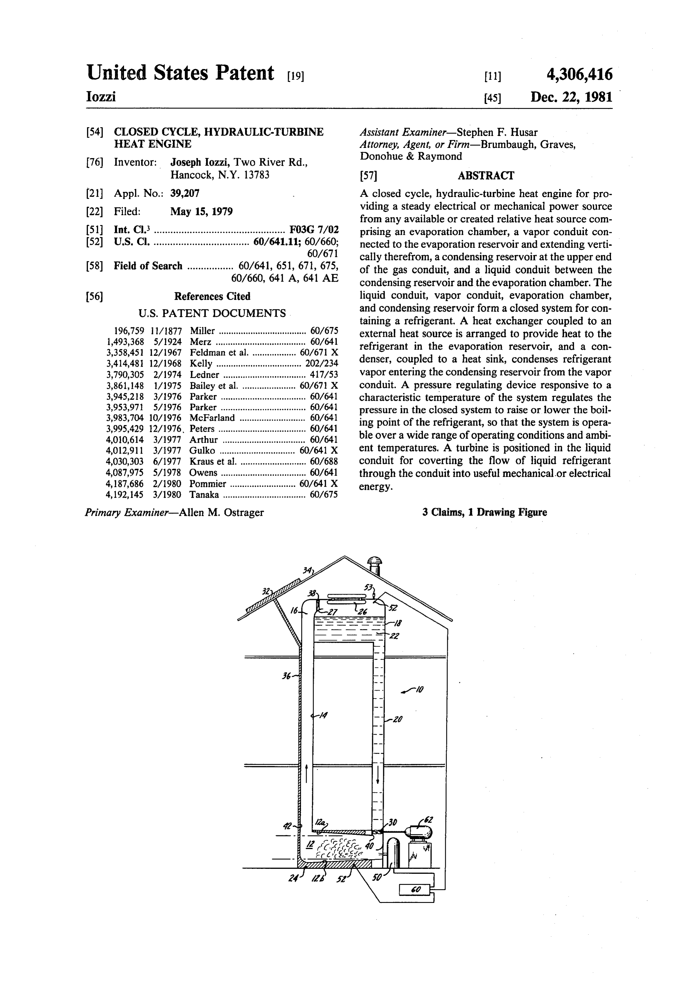
United States Patent (19) 11) 4,306,416 Iozzi 45) Dec. 22, 1981 (54) CLOSED CYCLE, HYDRAULIC-TURBINE Assistant Examiner-Stephen F. Husar HEAT ENGINE Attorney, Agent, or Firm-Brumbaugh, Graves, 76) Inventor: Joseph Iozzi, Two River Rd., Donohue & Raymond
Hancock, N.Y. 13783 57 ABSTRACT (21) Appl. No.: 39,207 A closed cycle, hydraulic-turbine heat engine for pro 22 Filed: May 15, 1979 viding a steady electrical or mechanical power source from any available or created relative heat source com 51) Int. Cl................................................. F03G 7/02 prising an evaporation chamber, a vapor conduit con 52 U.S. C. ................................... 60/641.11; 60/660; nected to the evaporation reservoir and extending verti 60/671 cally therefrom, a condensing reservoir at the upper end 58 Field of Search ................. 60/641, 651, 671, 675, of the gas conduit, and a liquid conduit between the 60/660, 641 A, 641 AE condensing reservoir and the evaporation chamber. The (56) References Cited liquid conduit, vapor conduit, evaporation chamber,
taining a refrigerant. A heat exchanger coupled to an 196,759 1 1/1877 Miller .................................... 60/675 external heat source is arranged to provide heat to the 1,493,368 5/1924 Merz ..................................... 60/641 refrigerant in the evaporation reservoir, and a con 3,358,451 12/1967 Feldman et al. ... 60/671 X 3,414,481 12/1968 Kelly ................................... 202/234 denser, coupled to a heat sink, condenses refrigerant 3,790,305 2/1974 Ledner ... ... 417/53 vapor entering the condensing reservoir from the vapor 3,861,148 1/1975 Bailey et al. ... 60/67 X conduit. A pressure regulating device responsive to a 3,945,218 3/1976 Parker ................................... 60/641 characteristic temperature of the system regulates the 3,953,971 5/1976 Parker ......... ... 60/641 pressure in the closed system to raise or lower the boil 3,983,704 10/1976 McFarland . ... 60/641 ing point of the refrigerant, so that the system is opera 3,995,429 12/1976, Peters .......... ... 60/641 4,010,614 3/1977 Arthur ... ... 60/641 ble over a wide range of operating conditions and ambi 4,012,911 3/1977 Gulko ...... ... 60/641 X ent temperatures. A turbine is positioned in the liquid 4,030,303 6/1977 Kraus et al., ... 60/688 conduit for coverting the flow of liquid refrigerant 4,087,975 5/1978 Owens ................................... 60/641 through the conduit into useful mechanical or electrical 4,187,686 2/1980 Pommier . ... 60/641 X energy.
4,192,145 3/1980 Tanaka .................................. 60/675
Primary Examiner-Allen M. Ostrager 3 Clains, 1 Drawing Figure
Page 2
Drawing sheet — no readable text.
Page 3
heat input, and the operating cycle of the system is
CLOSED CYCLE, HYDRAULC-TURBINE HEAT responsive to the instantaneous heat source and heat ENGINE sink conditions such that the unit operates at peak effi ciency over a wide variety of ambient conditions or
BACKGROUND OF THE INVENTION 5 changeable source and ambient conditions. This ex The present invention is a pollution free, closed cy tremely adaptable heat engine produces a reliable, cle, hydraulic-turbine heat engine which operates cheap, and steady output of electricity or mechanical readily from any environmentally available or created energy.
relative heat source or temperature differential, for More specifically, a heat engine according to the example from solar or geothermal energy, to generate 10 invention operates from a remote heat source, for exam useful mechanical or electrical energy. It is especially ple a solar collector. An evaporation chamber of the adapted to operate as an individual unit for homes or heat engine containing refrigerant, is in heat exchange small factories. contact with the collector. Liquid refrigerant in the A number of heat engines, which operate from occur 15 evaporation chamber absorbs input heat and, once gase ing or created heat sources, have been proposed in the ous, moves by pressure build up and convection up a past. Typically, these involve a high pressure, high vertically extending vapor output conduit. The vapor velocity heat exchange cycle, in which a refrigerant conduit opens into the upper portion of a condensing having a boiling point lower than the heat source is reservoir. A heat extractor, for example with cooling placed into heat exchange relationship with the heat 20 source and evaporated in a high pressure closed cham pipes or cooling fins, is placed in the condensing reser ber. The vapor, under pressure, is directed through a voir to act as a heat sink and condense the entering high speed gas turbine to generate electricity. vapor, which is then stored in the reservoir, the con in addition to the operating hazards of high pressure densed liquid refrigerant representing gravity potential steam or gas, engines of this type usually require a sub energy. The closed system is completed by a liquid stantial heat input and substantial temperature differen 25 conduit between the lower end of the condensing reser tials (between various phases of the cycle) to operate voir and the evaporation reservoir.
efficiently. The high throughput of vapor needed to A turbine in the lower end of the liquid conduit ex operate the turbine necessitates complicated piping and tracts (kinetic) energy from the flowing liquid refriger ducting, as well as the associated pumps, safety valves, ant to provide an output of useful mechanical or electri and other such regulatory equipment. This renders such 30 cal energy. A pressure adjustment device responsive to engines impractical, from both space and cost stand a characteristic temperature of the system is also pro points, for all but high output commercial applications. vided for varying the pressure in the closed system Also, variable heat source and heat sink temperatures thereby to raise or lower the boiling point of the refrig can cause these systems to operate inefficiently, or, with erant, depending upon operating conditions, so that the too great a temperature variance, can render them inop 35 heat engine operates efficiently over a wide range of erable. Engines of this type possess no inherent energy ambient temperatures or heat inputs. storing capabilities, and without separate accommoda tion, they operate only so long as a heat input is main The heat engine also operates from any available tained. Thus, although theoretically adaptable to a vari relative heat source. By "relative heat source', it is ety of heat energy sources, as a practical matter most meant that the heat source temperature is greater than heat engines are unsuitable for all but a limited number the available heat sink temperature. Thus either the heat of applications, and particularly, to large temperature source or heat sink may be at ambient temperature, as differentials of controlled, steady heat sources. These long as the temperature differential exists. cost and performance drawbacks render most heat en In a preferred form of the device, hot water from a gines or power generation systems using heat engines 45 solar collector panel communicates through a circula impractical for an individual home or small factory, or tion duct to the heat exchanger. The duct contacts the other such applications requiring modest but steady and vapor conduit along at least part of its length to help reliable power output. maintain the refrigerant in its gaseous state until it SUMMARY OF THE INVENTION reaches the condensing chamber. If desired, a fan may 50 be placed in the gas conduit for forced convection of
The present invention is a closed cycle hydraulic-tur the gas upwards toward the condensing reservoir. A bine heat engine which is relatively uncomplicated and governor is also provided in the liquid conduit for regu thereby inexpensive instructure and which may be used lating the flow of liquid through the turbine, and as an individual unit for supplying the on site electrical thereby the electrical or mechanical output. The gover needs of a residential home, or the electrical or mechan 55 ical needs of a small factory. The engine is pollution norThe may be incorporated as part of the turbine itself. heat engine according to the present invention, free, operates without high gas or steam pressures in the when coupled to a generator, supplies a steady continu system, without a gas or steam turbine, and without the ous output of electricity over long periods of time and need for high temperatures or high temperature differ entials. The unit is capable of operating from a wide variable operating conditions. It is ideally suited for variety of heat sources, for example solar, geothermal, supplying the electrical needs of individual homes or or waste heat, and is extremely adaptable to the particu providing a cheap, steady source of energy for electrol lar heat source chosen. The heat engine is capable of ysis. As opposed to an electrical output, the turbine operating not only from a heat source which provides could provide a mechanical output, for example to be only a small temperature differential, but a heat source 65 used in factories.
which is variable in tempearture or intermittent. The For a better understanding of the invention, reference unit has a built-in energy storage capacity to produce a may be had to the following detailed description, taken steady output despite fluctuations or interruptions of in conjunction with the accompanying drawing.
Page 4
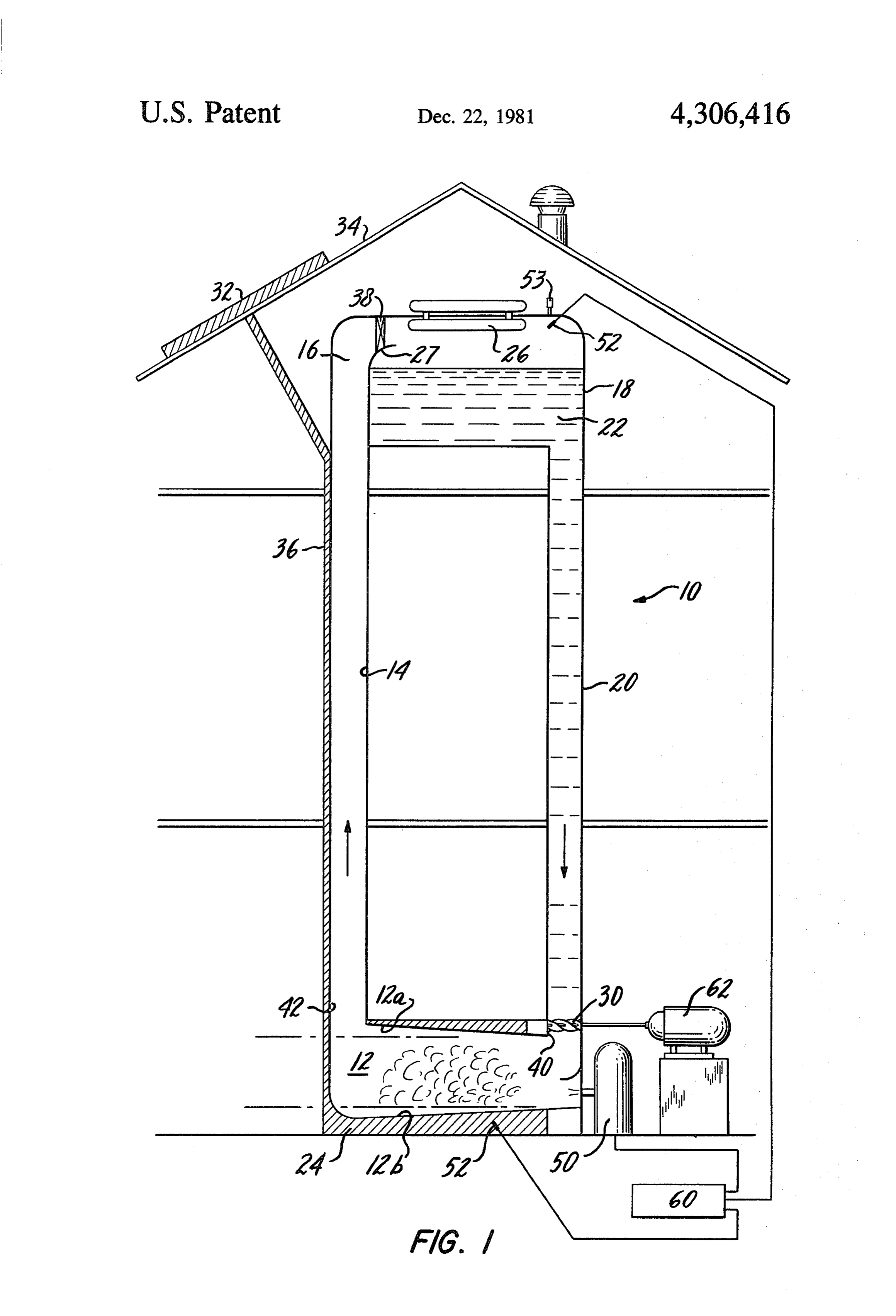
BRIEF DESCRIPTION OF THE DRAWING
uid conduit 20, so that the weight of the liquid refriger ant 22 in the reservoir 18 and liquid conduit 20 acts on
FIG. 1 is a schematic representation of a closed cycle the refrigerant driving the turbine 30. A pressure relief hydraulic-turbine heat engine in accordance with the valve 53 may also be connected to the system. present invention. 5 In operation, heat input to the solar collectors 32 is
DETAILED DESCRIPTION OF A PREFERRED
transmitted through the duct 36 to the heat exchanger
EMBODIMENT
24 to evaporate liquid refrigerant 22 in the evaporation reservoir 12. The refrigerant gas, through convection
Referring to the drawing, a closed cycle hydraulic or forced convection by the fan 38, and with a rise in turbine heat engine 10 is disposed within the interior 10 vapor pressure, rises through the gas conduit 14 into the walls of a house for generating electricity. The unit condensing reservoir. Upon entering the condensing comprises an evaporation chamber 12 having a vapor reservoir 18, the gas is directed through the cooling outlet conduit 14 extending vertically therefrom, a con rods 26 or fins, and, upon condensation, is collected in densing reservoir 18 connected to the upper end of the the reservoir 18. Condensed liquid 22 in the reservoir vapor conduit 14, and a return liquid conduit 20, with a 15 passes through the liquid conduit 20, through a turbine hydraulic turbine 30 arranged therein, connected be 30 and back into the evaporation reservoir to complete tween the lower end of the condensing reservoir 18 and the cycle.
the evaporation chamber 12. Output, either electrical or mechanical, is extracted The liquid conduit 20, vapor conduit 14, the evapora from the turbine 30, for example, by a generator 62 tion chamber 12 and the condensing reservoir 18 form a 20 coupled to the turbine shaft. Flow through the turbine closed system for a two-phase refrigerant heat exchange 30, and thus the output energy, is regulated by a gover cycle. nor, which may be part of the turbine 30 itself. Since the The evaporation chamber 12 has an inlet 40 con controlled flow from the reservoir 18 through the tur nected to the liquid conduit 20 and an outlet 42 con bine occurs independent of the evaporation portion of nected to the vapor conduit 14. The upper wall 12a of 25 the cycle, a steady output of electricity is generated the evaporation chamber 12 is sloped upwardly toward even with fluctuating heat inputs into the engine or the outlet 12 so that gas formed in the chamber 12 is during interruption of heat input (the length of such directed toward the gas conduit 14 and will not stagnate interruption before output is affected depending upon on the upper wall 12a or move toward the liquid con the capacity of the reservoir).
duit 20. Also, the lower wall 12b of the evaporation 30 Operating pressure within the closed system is con chamber 12 is sloped downwardly toward the outlet trolled by a pressure regulating device 50. Ambient side of the chamber such that liquid refrigerant 22 temperatures may tend to vary over a wide range from which has passed through the turbine 30 flows away day to day, which affects the cooling power of the from the turbine 30 toward the outlet side of the cham cooling rods 26 or fins, as well as the heat losses in the ber 12. 35 system. Moreover, heat input may vary considerably Heat may be provided to the heat exchanger 24 from depending upon conditions (in the case of a solar collec any available heat source, for example, a naturally oc tor 32, for example, depending upon seasons, tempera curring heat source (geothermal, lake water warmer ture and cloudiness). Regulating the system pressure than ambient air (or vice versa), waste heat from indus allows the heat engine to adapt to the particular condi trial processes, the waste heat from a furnace in a fac 40 tions. Raising the gas pressure in the system lowers the tory or home), or a created heat source (solar panels). boiling point of the working fluid, as might be required Two or more heat sources may also be used, together or in the case of reduced heat input. Reducing the system selectively (if, for example, each occurred intermit pressure raises the boiling point, and thus condensing tently or alternatively). In the illustrative embodiment, temperature of the working fluid when desired, if, for a solar collector 32 is positioned on the roof 34 of the 45 example, less cooling were available. house. Hot water in the pipes of the solar collector 32 is Temperature probes 52 (connected, e.g. to a potenti circulated, by any suitable means, through a duct 36 ometer, not shown), placed in the heat exchanger 24 from the collector 32 to the heat exchanger 24 and back and adjacent the cooling rods 26 or fins monitor the (via a separate duct) to the collector 32. As shown in the temperature of the evaporation causing fluid from the drawing, the duct 36 is also in heat contact relationship 50 solar collector 32 and the cooling capacity (tempera with the vapor conduit 14 along at least part of the ture) of the rods 26 or fins in the upper end of the heat length of the vapor conduit 14 to help maintain the engine. The probes 52 are connected to a controller 60 refrigerant in a gaseous state as it travels through the acting on the pressure regulator 50, to lowered the vapor conduit 14. system pressure (and thus lower the refrigerant boiling The upper end 16 of the vapor conduit 14 opens into 55 point) when the heat exchanger 24 temperature falls the condensing reservoir 18, where the incoming refrig below a predetermined minimum, and to raise the sys erant gas is directed through a plurality of heat exhange tem pressure (and thus raise the refrigerant condensing cooling rods 26 to condense the gas. A cooling medium, point) when the temperature of the cooling rods 26 rises e.g. water, is pumped through the rods to act as a heat above a predetermined maximum. Thus the boiling (and sink. In place of the cooling rods, 26, any other heat condensing) temperature of the refrigerant is constantly exchange medium will suffice, for example fins, or the adjusted to remain between the temperature in the condenser walls themselves, cooled by the ambient evaporation chamber and in the condensing reservoir. temperature of the surroundings. A fan 38 may also be The preferred boiling temperature of the refrigerant placed in the upper end 16 of the gas conduit 14 as a depends upon the relative efficiency of the heat ex means of force convection of the gaseous refrigerant. 65 change, and thus the prevailing temperatures, in both Once condensed, a lip 27 prevents backflow of the liq the evaporator 12 and the condensor 18. If the efficien uid refrigerant 22 down the vapor conduit 14. Instead cies were equal, the ideal boiling point, for maximum the liquid phase 22 is directed entirely through the liq evaporation and condensation, would lie halfway be
Page 5
tween the two temperatures (of the heat exchanger 24 (a) an evaporation chamber for containing a refriger and the cooling rods 26). Preferably, the controller 60 ant and a vapor of said refrigerant, forming respec actuates the pressure regulator 50 to maintain the opti tively a liquid containing zone and a vapor contain mum boiling point. ing zone thereabove;
The choice of refrigerant is likewise influenced by the (b) a condensing reservoir vertically spaced from said prevailing system temperatures and has a boiling point evaporation chamber and supported by said build lower than the prevailing temperatures of the heat ing for containing a combination of said refrigerant Source and higher than the temperature of the cooling and said vapor, forming respectively a liquid-con rods or fins. The refrigerant chosen preferably also has taining Zone and a vapor-containing zone there a low latent heat of vaporization. This facilitates O above;
changes of state with minimum heat input in the evapo (c) a vapor conduit communicating between the ration chamber 12, and minimum cooling requirements vapor containing zone in said evaporation chamber in the condensor 18, and thus provides a maximum and the vapor containing zone in said condensing circulation of refrigerant through the system with a 15 reservoir, and sized to permit convective transfer minimal temperature differential between the heat of vapor without resistance to said condensing
source and heat sink.
Finally, the system can be tailored to the individual (d) a liquid conduit communicating between the liq uid containing zone of said condensing reservoir requirements of the consumer. The maximum power and said evaporation chamber, the liquid conduit, output capability of the heat engine depends upon sev 20 vapor conduit, evaporation chamber, and condens eral interrelated factors, e.g. the height of the liquid ing reservoir forming a closed system for contain column in the liquid conduit and the cross-sectional size ing said refrigerant;
of the liquid conduit (affecting the weight force of the (e) heat source means having a heat exchanger dis liquid on the turbine), the heat sink and heat source posed in the liquid containing zone of said evapora temperatures, and the heat transfer efficiencies, which 25 tion chamber for evaporating the refrigerant; can thus be chosen according to need. It is anticipated (f) heat sink means having a heat exchanger disposed that a unit of about 20-30 feet will supply the electrical in the vapor containing zone of said condensing needs of an individual home. reservoir for condensing refrigerant vapor entering The self-contained heat engine according to the in said reservoir from said vapor conduit; vention operates safely, efficiently, and pollution free 30 (g) means for preventing liquid refrigerant in said with a minimum of temperature difference between the reservoir from flowing back down said vapor con input 12 and extraction 18 portions of the cycle (since duit and for directing vapor in said evaporation the pressure regulator 52 maintains the evaporation chamber toward said vapor conduit and away from temperature between the two), without high operating said liquid conduit;
pressures or high velocity gas turbines, and produces 35 (h) pressure detection means in one of the vapor con steady, reliable power over a wide range of steady state taining zone of said evaporation chamber, the or variable heat source inputs. At the same time, the unit vapor containing zone of said condensing reser does not require the usual sophisticated, expensive, and voir, and said vapor conduit for detecting the pres high maintenance components usually associated with sure of said refrigerant vapor; heat engines, and is thus practical for use in homes and (i) means for detecting the temperature in said heat small factories as an individual supply of electricity or source and heat sink;
mechanical power. (j) pressure regulating means including control means The above described embodiment represents one responsive to said detected temperatures for vary form of the invention. Modifications and variations of 45 ing the pressure in the closed system thereby to this embodiment, without departing from the inventive raise or lower the boiling point of the refrigerant; concepts disclosed herein, will be apparent to those (k) turbine means in said liquid conduit for converting skilled in the art. For example, instead of using a higher the flow of liquid refrigerant through the liquid temperature heat source and ambient air as the heat conduit into useful energy; and (l) governor means for regulating the flow of liquid sink, the ambient temperature may act as the heat 50 into said evaporation chamber. source for a low boiling point liquid, where a colder 2. A heat engine according to claim 1, wherein said heat sink is available, as long as a "relative' heat source heat source means comprise a solar collector and heat (i.e. temperature differential) is available. All such mod transfer means in heat exchange contact with the vapor ifications and variations are intended to be within the conduit along at least part of its length. scope of the present invention, as defined in the follow 55 3. A heat engine according to claim 2, wherein said ing claims. evaporation chamber has an upper wall sloped up I claim: wardly toward said vapor conduit for directing vapors 1. A closed cycle, hydraulic-turbine heat engine for in said evaporation chamber toward said vapor conduit supplying electrical or mechanical power for a building, and away from said liquid conduit. comprising:
Provenance
- Collection
- Cited prior art
- Original PDF
- patentimages.storage.googleapis.com →
- Filed
- 1979-05-15
- Pages
- 5
- Method
- pdftotext (the PDF's own text layer) + pdftoppm 300dpi page scans
- Source
- Google Patents bibliographic record
- Granted
- 1981-12-22
- Inventors
- Joseph Iozzi
- Transcribed from
- patentimages.storage.googleapis.com →