patent · US3089670
Solar powered vehicle
14 May 1963
Page 1
Drawing sheet — no readable text.
Page 2
United States Patent Office 3,089,670 Patented May 14, 1963
3,089,670 FIG. 4 is an elevational view of a control system for SOLAR POWERED WEHICLE stabilizing means; and
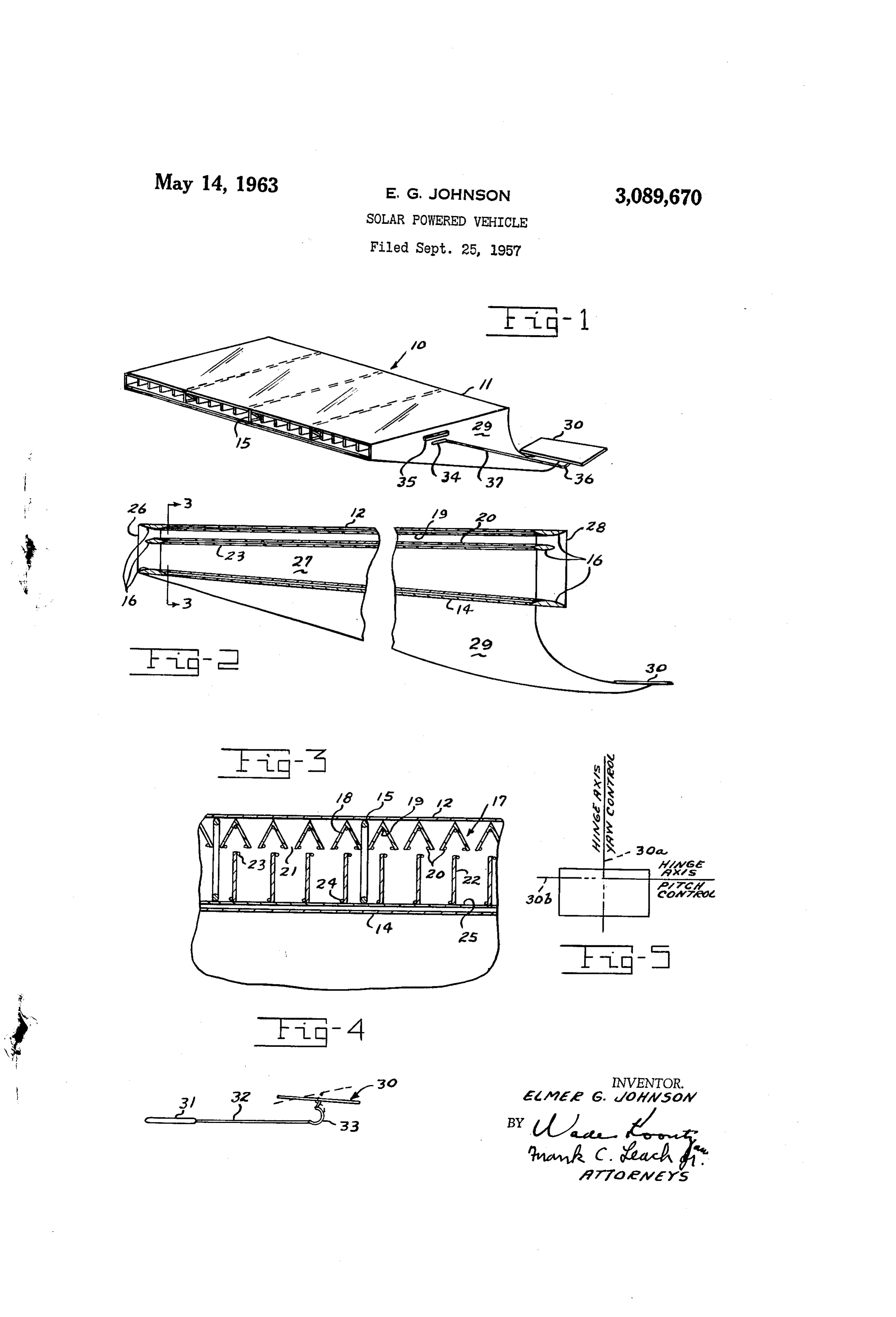
Ener G. Johnson, 54 Grand Ave., Fairborn, Ohio FIG. 5 is a plan view of one of the stabilizing means. Fied Sept. 25, 1957, Ser. No. 686,264 Referring to the drawing and particularly FIG. 1, there 6 Claims. (C. 244-74) is shown an aircraft 10 having a wing 1 of substantially (Granted under Title 35, U.S. Code (1952), sec. 266) rectangular shape although a swept wing could be em ployed, if desired. The wing 15 has an upper surface 12,
The invention described herein may be manufactured which is substantially transparent to solar radiation. The and used by or for the United States Government for gov material of the upper surface may be any material having ernmental purposes without payment to me of any royalty 0. a high tensile strength, a low specific weight, and sub thereon. stantially transparent to solar radiation. One material This invention relates to an aircraft and its power plant might be a polyester film having the trademark "Mylar' and, more particularly, to a lift sustained flying vehicle and made by the Du Pont Company; this material is sub consisting primarily of an airframe-propulsive unit and stantially transparent to solar radiation and has the tensile control system having its power derived through the con 5 strength of hardened aluminum but only half the specific version of solar radiation. weight. The lower surface 4 of the wing 1 is preferably If intercepted outside the earth's atmosphere, solar radi made of the same material as the upper surface but it is ation amounts to approximately .174 horsepower per coated or metalized by well known means to form a re square foot of area normal to the incident solar radiation. flective surface.
At any particular location in the earth's atmosphere, the 20 The surfaces 2 and 4 of the wing 11 are joined to magnitude of this radiation is a function of the latitude, gether by a plurality of ribs 15. The ribs 15 form a truss the time of day, the time of year, and weather conditions. type structure and preferably are made of hollow tubular Considering all of these factors, the major requirement for elements having stiffeners in the interior thereof to add a solar powered vehicle is that it be light enough in weight strength thereto. The elements may be of any material to sustain itself on the portion of the intercepted solar 25 having a high strength to weight ratio such as balsa Wood, radiation energy that can be converted for propulsive pur metals, or ceramics, for example. A plurality of braces poses. The present invention satisfactorily meets this 26 extends between the ribs 25 to add spanwise rigidity requirement. and function as anchor points for the upper and lower While a solar vehicle may be operated at any altitude dependent upon the wing loading of the vehicle, it has 30 surfaces of the wing 11 and other structure of the aircraft 9. While the braces 16 are shown disposed only at the been ascertained that a vehicle of this type may operate front and rear of the aircraft 10, it should be understood more satisfactorily at high speeds at high altitude. In that they may be employed throughout the length of the fact, the combination of energy availability, energy con chord of the wing.
version efficiency, aerodynamic-propulsive efficiency and The lower surface 4 of the wing i is at a predeter speed for optimum performance is best realized in the 35 mined angle with respect to the upper surface 2 of the altitude range of 100,000-300,000 feet. Under such con wing. This particular angle is determined by the altitude ditions, the weight of the vehicle must be extremely small; at which the aircraft will fly, the Mach number, and the in fact, the load per unit lifting surface of the vehicle at friction drag coefficient. The friction drag coefficient is these altitudes is comparable to that of a toy model air a function of the Reynolds number of the flow over the plane. The structure of the vehicle must not only be 40 wing 1. Since optimum results are obtained when the extremely light in weight it must also be sufficiently strong friction drag coefficient is equal to the wave drag coeffi to withstand the aerodynamic loads that will be encoun cient, the particular angle of the lower surface 14 of the tered. However, these loads are very low; for exampie, wing Ali with respect to the upper surface 2 is easily at a speed of 1,000 miles per hour at an altitude of 240,000 45 calculated.
feet, the structure of the aircraft is subject to an aero In one type of operation of this vehicle, it is desired dynamic load comparable to that which would be exerted that the aircraft move at a speed relative to the earth at thereon at a speed of 10 miles per hour near Sea level. which it will maintain a position with respect to the Sun Since it is desirable for an aircraft to carry a pay load, Such that a continuous supply of solar radiation energy such as equipment to transmit data to the ground, for may be intercepted for propulsive purposes. From the example, it is necessary that the weight of the aircraft 50 position of an observer on the sun, this requires the earth structure be less than its wing loading capability. to rotate under the aircraft and the aircraft to remain An object of the present invention is to provide an air with the atmosphere as the earth orbits about the sun. vehicle powered by Solar energy. In this type of operation, the aircraft is in a position such Another object of this invention is to provide a power 55 that any equipment thereon may scan a large portion of plant for an aircraft that derives its energy from the sun. the earth and transmit this observed data, for example. Other objects of this invention will be readily perceived It should be noted that this aircraft does not depend on from the following description. centrifugal force but on aerodynamic lift to remain in This invention relates to a power plant for an aircraft position.
or the like comprising an air ramjet, a solar radiation trap, 60 A radiation trap 17, which is preferably of accordion means to absorb the radiation energy converting it into shape, is disposed beneath the upper surface 2 of the heat energy and transferring the heat energy to the air wing 11 and adjacent thereto. While a radiation trap of passing through the ramjet whereby the ramjet produces this type is preferred, it will be understood that any type thrust. of trap providing a reasonable efficiency and extremely The attached drawing illustrates a preferred embodi 65 light in weight may be employed. The radiation trap 17 ment of the invention, in which: is formed of a plurality of angle-shaped members 18 FIG. 1 is a perspective view of the aircraft and power made of a very thin metallic membrane. The angle plant of the present invention; shaped members 18 are nontransparent to solar radiation FIG. 2 is a sectional view, partly in elevation, of the and have a surface of good mirror qualities. One method aircraft of FIG. 1; 70 of forming this metallic-like membrane is by dissolving FIG. 3 is a sectional view taken along the line 3-3 “Mylar' from commercially metalized “Mylar.” The of FIG. 2; metalized "Mylar' may be made by vaporizing metal
Page 3
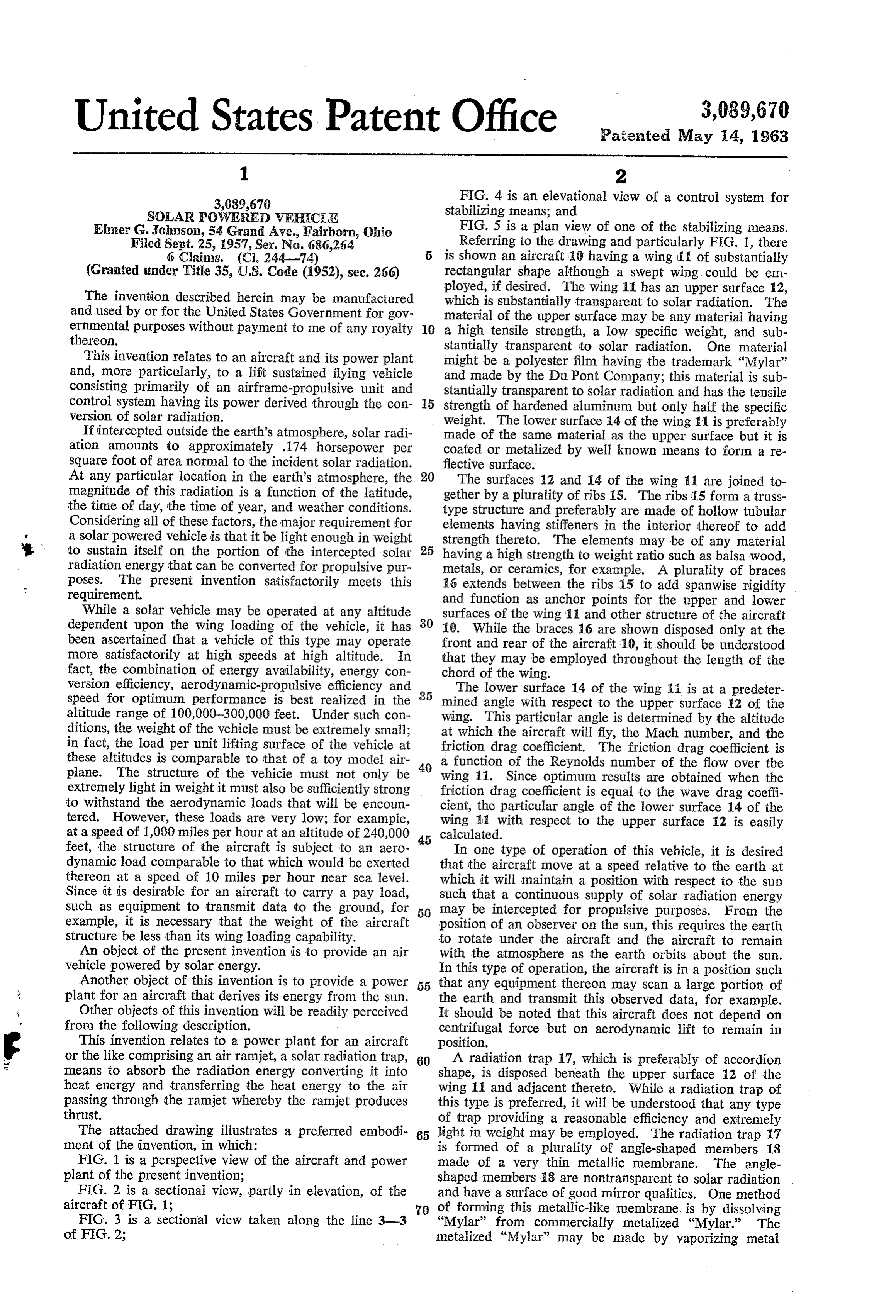
under a vacuum by an electric arc in the vicinity of a flow channel for an exhaust outlet or nozzle 28 of the sheet of "Mylar.” The metal deposited upon the "Mylar' passage 27 of the ramjet. Since the outlet or nozzle 28, has a thickness depending upon the exposure time. which is divergent, occupies the area of the airfoil that The metal of the metallic membrane, which is formed would otherwise be a blunt trailing edge, the wake drag, by dissolving the "Mylar' from the commercially metal which normally occurs with an airfoil of this type, is ized "Mylar,” may be any metal having a high surface eliminated.
reflectivity, such as aluminum, of approximately .00006 A member 29 is secured to each side of the wing 11 inch thickness. The metallic membrane of aluminum and has stabilizing means including a member 30 pivotally could be formed from some other material by some proc pivot secured thereto. Each of the members 3i) is hinged to ess other than dissolving “Mylar,' if desired. 0. about an axis 30a parallel to the longitudinal axis The upper edges of the angle-shaped members 18 of of the vehicle and an axis 30b parallel to the lateral axis. the radiation trap 7 are supported by stressed steel wires By pivotally connecting each of the members 30 about the 19, which are secured beneath the apexes of the angle axis parallel to the longitudinal axis of the vehicle, yaw members 18 and to the lower edges of the uppermost control is provided. Similarly, the pivoting of the mem braces 16. The lower edges of the angle-shaped members ber 30 about the axis parallel to the lateral axis of the 18 are supported by stressed steel wires 20, which are vehicle permits pitch control.
secured to the upper edges of the center braces ió, as The actuation of the member 30 to provide pitch con shown in FIG. 2. trol may be accomplished through a tube 31, which is While the radiation trap 17 is shown as a geometrical filled with ether, for example. This tube 31 preferably is type, it will be understood that the trap also could be 20 disposed beneath the upper surface 12 and is disposed parallel to the longitudinal axis of the aircraft. The tube based upon principles, which are classified as thermody 31 is connected by a pressure line 32 (see FIG. 4) to an namic or optical. It is only necessary that the radiation actuating member 33 including a Bourdon tube. The efficiency of the trap be very high. This efficiency is de fined as the ratio of the difference of the energy of the actuating member 33 is connected to the member 30 to intercepted solar radiation and the energy lost due to re 25 pivot it about the axis 30b. The ether within the tube 31 radiation to the energy of the intercepted solar radiation. has a certain predetermined temperature at which the The radiation trap is designed to minimize the value of member 30 will remain in the desired position to maintain the energy lost due to reradiation. the surface 12 normal to the rays of the sun. If the air It should be understood that the incident solar radiation craft should pitch up or down, the heat energy of the is composed of essentially parallel rays while the reradi 30 solar the radiation, which is intercepted by the ether within tube 31, is reduced to thereby create a lower tempera ation rays are randomly directed. The geometry of the ture of the ether. This reduces the volume of the ether structure of the radiation trap 17 is such that the incident and, accordingly, actuates the Bourdon tube of the actu solar radiation is focused through openings 21, which are formed between the lower edges of adjacent angle-shaped 35 ating member 33 to exert a force on the control member 30 in a direction that produces an aerodynamic force on members 18. The maximum deviation of the Sun's rays the aircraft to restore it to its proper flight attitude. from parallel is an angle of seventeen minutes; this devi A tube 34, which contains ether, is secured to each ation is accounted for in the geometrical analysis of the member 29 and is shaded from the normal rays of the radiation trap 7. It is necessary that the apex angle of the angle-shaped members 18 be extremely small for the 40 sun by a member 35, which is secured to the member 29 and extends therefrom at substantially right angles. The radiation efficiency of the trap 17 to be high. tube 34 is connected to an actuating member 36, which After passing through the openings 21, the incident solar includes a Bourdon tube, by a pressure line 37. If the rays are intercepted by an absorber, which includes a aircraft should yaw out of its normal flight path, one of plurality of blackened plates 22. The plates 22 are sup the tubes 34 will be exposed to rays of the sun to thereby ported at their upper ends by stressed steel wires 23, which are secured to the lower edges of the middle braces 16. 45 expand the ether within the tube. This results in the actu ating member 36 moving the control member 30 about
The plates 22, which function as heat transfer fins, have the hinge axis 30a.
their lower ends secured to stressed steel wires 24, which This stabilizing mechanism insures that the upper sur are secured to the upper edges of the lowermost braces 16. A flat plate 25, which is parallel to the lower surface face 12 of the wing 11 remains substantially perpendicular 14 of the wing 11, is secured to the lower ends of the 50 to the rays of the sun and parallel to the airflow; this in Sures that the power produced by the ramjet is not sub plates 22 and to the wires 24 (see FIG. 3). The plates stantially reduced. The yaw and pitch control systems 22 and the flat plate 25 of the radiation absorber are also act as speed control means since the aircraft flies, formed of a high temperature material such as chromium, for a given altitude, at an optimum speed that keeps the for example. The plates are blackened to minimize the upper surface 12 of the wing 11 properly oriented with reflective qualities of the metallic membrane. Since the respect to the rays of the sun.
lower surface 14 of the wing 11 is reflective, any rays In the operation of the present invention, it will be radiated downward by the plate 25 are reflected by the readily seen that the rays of the sun pass through the radi lower surface 14. After the absorber has been subjected ation trap 17 into the radiation absorber wherein its plates to the rays of the sun, the temperature of the absorber 22 and 25 intercept the rays to absorb the solar energy increases sufficiently to insure that the metal behaves 60 thereof. This increases the temperature of the plates 22 nearly as a "black body' regardless of the conditions of and 25 of the absorber and makes possible the transfer the surfaces of the plates 22 and 25. of heat energy to the air flowing through the ramjet pas The flat plate 25 and the transparent upper surface 12 sage 27 in which the absorber is disposed. The resulting of the wing 11 cooperate to form a ramjet therebetween. increase in the temperature of the air produces a thrust The forward spanwise braces 16 are appropriately shaped 65 whereby the aircraft is propelled forward. The thrust so that they function to provide the proper flow channel produced by the air flowing through the ramjet increases for a convergent inlet 26 to the ramjet. A passage 27, which is formed between the flat plate 25 and upper sur in proportion to the increase in efficiency of the radiation trap 17. Likewise, an increase in the efficiency of the face 12, diverges from the inlet 26 at the front of the wing toward the rear of the wing 11. When the vehicle is oper 70 radiation absorber increases the thrust. It is necessary to employ supplemental means to launch ating at SuperSonic speeds, the passage 27 also functions as a diffuser since a shock wave is genertaed at the con the aircraft to the altitude at which it is desired to operate. vergent inlet 26 so that the speed of air flowing through One method of furnishing auxiliary power to move the the passage 27 is subsonic. The spanwise braces 16 at aircraft to its operating altitude includes the use of a the rear of the wing 11 are shaped to form the proper balloon to take the aircraft to approximately 100,000 feet
Page 4
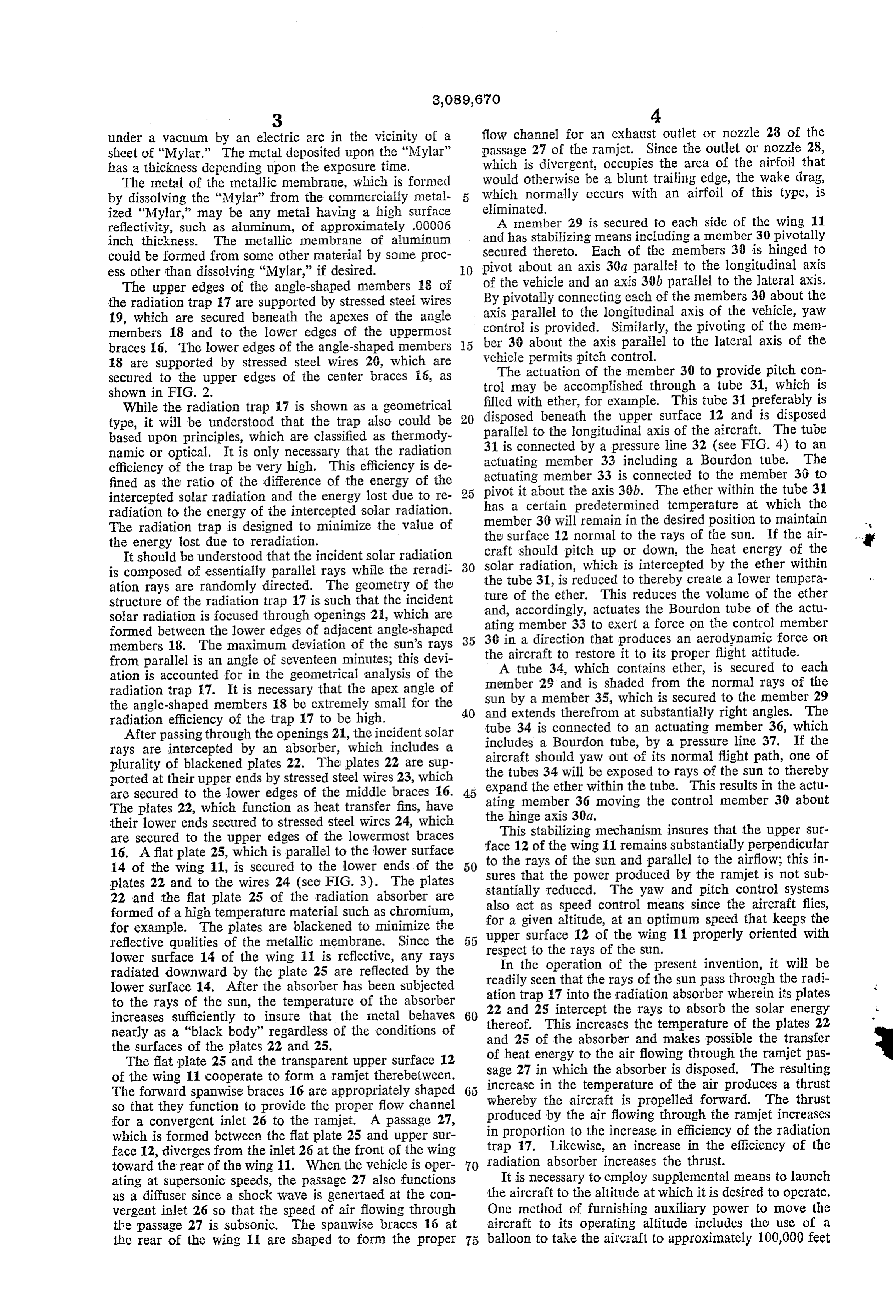
and a rocket powered carrier or platform to move the absorption of solar radiation to the air flowing through aircraft the remaining distance to its desired altitude and the ramjet to provide thrust to power the aircraft. Speed. 4. An aircraft including a wing having an upper sur Since the aircraft depends solely on solar energy for face substantially transparent to solar radiation and a its propulsion, there is no requirement for fuel and the reflective lower surface, the lower surface of the wing aircraft may remain in the air indefinitely. Such an ad ibeing at a predetermined angle to the upper surface of vantage permits the use of this device, for example, to the wing, a solar radiation trap disposed adjacent the continuously transmit physical data concerning conditions upper surface of the wing to trap energy of solar radi of state and constituents of the earth's atmosphere at high ation, means for absorbing solar radiation received from altitudes; to televise pictures of the earth's surface or its 10 the heat trap, a ramjet disposed between the surfaces of surrounding cloud formations. the wing, said ramjet having a passage formed between For purposes of exemplification, a particular embodi the upper surface of the wing and a lower wall parallel ment of the invention has been shown and described ac cording to the best present understanding thereof. How to the lower surface of the wing, means to transfer heat energy obtained from the means for absorption of solar ever, it will be apparent that changes and modifications 5 radiation to the air flowing through the ramjet to provide in the arrangement and construction of the parts thereof thrust to power the aircraft, and stabilizing means se may be resorted to without departing from the true spirit cured to the aircraft to maintain the upper surface of and scope of the invention. the wing substantially normal to the impinging sun rays. I claim: 5. A solar powered aircraft including a wing having 1. A power plant for an aircraft or the like comprising 20 an upper and a lower surface spaced apart to provide a ramjet including an inlet and a divergent passage hav a chamber coextensive spanwise and chordwise of the ing an upper surface essentially transparent to Solar wing and having a convergent inlet and divergent outlet radiation, the lower surface of said passage being at a and providing an unobstructed path for the flow of air predetermined angle to the upper surface, a solar radia therethrough, the upper surface of the wing being trans tion trap disposed adjacent the transparent upper surface 25 parent to solar radiation and the lower surface of the of the passage and directing solar radiant energy into wing being reflective to solar radiation, a radiation trap said divergent passage, and means disposed in the passage positioned beneath said transparent upper surface and s to absorb the solar radiation energy and to transfer said heat energy to the air passing through the passage where heat absorbing means in said chamber adapted to receive heat energy from said radiation trap and to transfer heat by the ramjet produces a thrust. 30 to the air flow therethrough and induce ramjet action, 2. An aircraft including a wing having an upper Sur the thrust produced propelling the aircraft. face substantially transparent to solar radiation and a 6. An aircraft including a wing having an upper sur reflective lower surface, the lower surface of the wing face substantially transparent to solar radiation imping being at a predetermined angle to the upper surface of ing thereon, a ramjet passage disposed between the upper the wing, a solar radiation trap disposed adjacent the 35 and lower surfaces of the wing, a solar heat trap disposed upper surface of the wing to trap energy of solar radi beneath the transparent upper surface of the wing and ation, a ramjet disposed between the surfaces of the directing the trapped solar energy into said ramjet pas wing, said ramjet having a passage formed between the Sage, and heat absorbing and reradiating means within upper surface of the wing and a lower wall parallel to 40 said ramjet passage absorbing the solar heat energy di. the lower surface of the wing, and means within the ram rected into said passage from the heat trap and transfer jet passage to absorb heat directed thereto from said heat ring heat energy to the air flowing through the ramjet trap and to transfer heat energy obtained from the ab passage to thereby produce a thrust to propel the air sorption of solar radiation to the air flowing through craft.
the ramjet to provide thrust to power the aircraft. References Cited in the file of this patent 3. An aircraft including a substantially rectangular 45 UNITED STATES PATENTS shaped wing having an upper surface substantially trans parent to Solar radiation and a reflective lower surface, 246,626 Morse ---------------- Sept. 6, 1881 the lower surface of the wing being at a predetermined 1,700,675 Goddard -------------- Jan. 29, 1929 angle to the upper surface of the wing, a solar radiation 2,467,885 Freund --------------- Apr. 19, 1949 trap disposed adjacent the upper surface of the wing to 50 2,680,437 Miller ----------------- June 8, 1954 trap energy of Solar radiation, a ramjet disposed between 2,700,515 Reder ----------------- Jan. 25, 1955 the Surfaces of the wing, said ramjet having a passage 2,836,379 Salmon --------------- May 27, 1958 formed between the upper surface of the wing and a lower 2,877,965 Wakefield ------------- Mar. 17, 1959 Wall parallel to the lower surface of the wing and adapted 55 2,916,230 Nial ------------------ Dec. 8, 1959 to receive radiant energy transmitted by said heat trap, FOREIGN PATENTS and means to transfer heat energy obtained from the 748,700 Great Britain ----------- May 9, 1956
Provenance
- Collection
- Cited prior art
- Original PDF
- patentimages.storage.googleapis.com →
- Filed
- 1957-09-25
- Pages
- 4
- Method
- pdftotext (the PDF's own text layer) + pdftoppm 300dpi page scans
- Source
- Google Patents bibliographic record
- Granted
- 1963-05-14
- Inventors
- Elmer G Johnson
- Transcribed from
- patentimages.storage.googleapis.com →