patent · US5486345
Treatment of gases
23 January 1996
Page 1 — bibliographic record
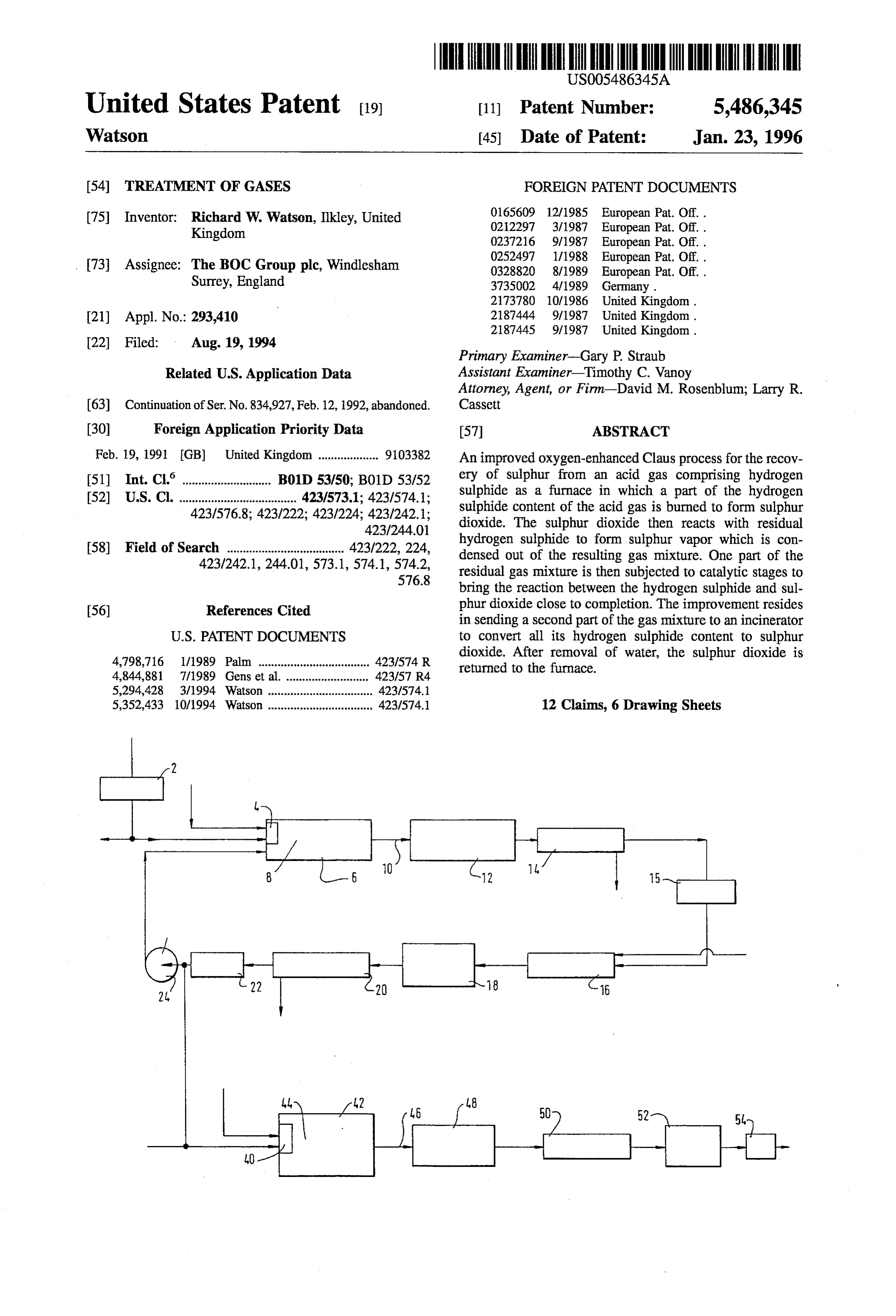
United States Patent (19) 11) Patent Number: 5,486,345 Watson 45 Date of Patent: Jan. 23, 1996 54 TREATMENT OF GASES FOREIGN PATENT DOCUMENTS
(75) Inventor: Richard W. Watson, Ilkley, United 0212297 3/1987 European Pat. Off. . Kingdom 0237216 9/1987 European Pat. Off. .
(73) Assignee: The BOC Group plc, Windlesham 0328820 8/1989 European Pat. Off.. Surrey, England 3735002 4/1989 Germany.
21 Appl. No.: 293,410 21874.44 9/1987 United Kingdom.
Primary Examiner-Gary P. Straub
Related U.S. Application Data Assistant Examiner Timothy C. Vanoy Attorney, Agent, or Firm-David M. Rosenblum; Larry R.
63 Continuation of Ser. No. 834,927, Feb.12, 1992, abandoned. Cassett (30) Foreign Application Priority Data (57) ABSTRACT Feb. 19, 1991 (GB) United Kingdom ................... 91.03382 An improved oxygen-enhanced Claus process for the recov (51) Int. CI.' ...................... B01D 53/50; B01D 53/52 ery of sulphur from an acid gas comprising hydrogen (52) U.S. Cl. ..................................... 423/573.1; 423/574.1; sulphide as a furnace in which a part of the hydrogen 423/576.8; 423/222; 423/224; 423/242.1; sulphide content of the acid gas is burned to form sulphur 423/244.01 dioxide. The sulphur dioxide then reacts with residual 58) Field of Search ..................................... 423/222, 224, hydrogen sulphide to form sulphur vapor which is con 423/242.1, 244.01, 573.1, 574.1, 574.2, densed out of the resulting gas mixture. One part of the 576.8 residual gas mixture is then subjected to catalytic stages to bring the reaction between the hydrogen sulphide and sul 56) References Cited phur dioxide close to completion. The improvement resides in sending a second part of the gas mixture to an incinerator
4,798,716 1/1989 Palm ................................... 423,574 R dioxide. After removal of water, the sulphur dioxide is returned to the furnace.
4,844,881 7/1989 Gens et al. .. ... 42.3/57 R4 5,294,428 3/1994 Watson ................................. 423/574.1 5,352,433 10/1994 Watson ................................. 423/574.1 12 Claims, 6 Drawing Sheets
e - - -
Page 2
Drawing sheet — no readable text.
Page 3
Drawing sheet — no readable text.
Page 4
Drawing sheet — no readable text.
Page 5
Drawing sheet — no readable text.
Page 6
Drawing sheet — no readable text.
Page 7
Drawing sheet — no readable text.
Page 8
TREATMENT OF GASES In order to improve the conventional Claus process, it is now well known to use pure oxygen or oxygen-enriched air
This is a continuation of application Ser. No. 07/834,927, instead of air unenriched in oxygen to support combustion of filed Feb. 12, 1992 now abandoned. the hydrogen sulphide. This substitution reduces the propor tion of nitrogen in the gas stream that flows through the
Claus plant and accordingly enables a plant of given size to
BACKGROUND OF THE INVENTION be uprated. In practice, however, in many plants, the amount This invention relates to the treatment of gases. In par of uprating that can be achieved by this method is limited as ticular, it relates to treatment of a gas stream comprising 10 there is a tendency for the reduced volume of nitrogen to lead to higher temperatures within the furnace that cannot be hydrogen sulphide.
Gas streams comprising hydrogen sulphide are typically withstood by the waste heat boiler associated with the furnace or by the refractory lining of the furnace. Indeed, the produced as waste products or by-products in many indus more concentrated in hydrogen sulphide the gas stream, the trial processes. For example, acid gas streams comprising less becomes the amount of uprating can be achieved by carbon dioxide and hydrogen sulphide are typically pro 15 simple substitution of oxygen for air. duced during oil refinery operations in which sulphur is There have therefore been a number of proposals in the art removed from crude oil. It is necessary to treat such hydro to tackle the problem of excessive temperature rise that can gen sulphide containing streams before discharging them to be caused by the substitution of oxygen for air. In EP-A-0 the atmosphere so as to reduce or remove altogether their 165609 it is disclosed that enriching the combustion air with content of sulphur-containing gases. One well known, 20 oxygen to a level of 70 mole percent oxygen produces a widely practised process for the treating of gas stream calculated theoretical adiabatic flame temperature of about comprising hydrogen sulphide is the Claus process. This 3750° F (2065° C), but that by recycling part of the gas process is based on the reaction between hydrogen sulphide stream leaving the first sulphur condenser (which is inter and sulphur dioxide to form sulphur vapour and water mediate the furnace and the first catalytic stage) to the vapour in accordance with the equation: 25 furnace itself so as to moderate the flame temperature, this temperature can be kept to below 2800° F (1538° C) while achieving an increase in throughput of hydrogen sulphide in
Sulphur exists in the vapour phase in a number of different the range of 50 to 100% by volume. This result can be molecular species such as S2, S and Ss according to the 30 achieved since the recycle stream consists largely of water temperature. vapour (steam) which has a higher molar heat capacity than The first stage of the Claus process is to burn approxi nitrogen. A number of alternative methods of moderating the mately a third of the hydrogen sulphide in the incoming gas flame temperature have been proposed. For example, GB stream to form sulphur dioxide and water vapour in accor A-2 173 780 proposes that the temperature be moderated dance with the equation: simply by introducing liquid water into the flame zone. In 35 EP-A-0-252-497 it is proposed to use a temperature mod erating stream of sulphur dioxide. The sulphur dioxide may be imported or generated by burning a small fraction of
This combustion reaction takes place in a suitable furnace hydrogen sulphide feed or liquid sulphur product in a and normally air is used as a source of oxygen for the separate process unit. Alternatively, it can be generated from purposes of combustion. Reaction between the sulphur 40 a back end Claus process stream (which generally contains dioxide and hydrogen sulphide starts in the combustion zone about 3 moles per 100 moles of hydrogen sulphide feed). and then continues downstream of the combustion Zone. It Additional advantages that can be obtained from this method is, however, a feature of the Claus reaction that at the are reduced oxygen consumption, increased percentage con temperature that is created by the combustion of hydrogen version of hydrogen sulphide and an increase in the capacity sulphide, it is not possible (with air) to convert more than 45 of the furnace in which the hydrogen sulphide is burnt. about 75% of the remaining hydrogen sulphide to sulphur by An alternative approach to using pure oxygen or oxygen reaction with sulphur dioxide, and typically between 50 to enriched air to improve the capacity or throughput of a Claus 70% of the hydrogen sulphide is so converted. It is, however, process is to conduct the combustion of the hydrogen possible to achieve a higher total conversion in the presence sulphide in two separate furnaces. Accordingly, the overall of a catalyst at a reaction temperature in the order of 200 to 50 amount of heat generated by the combustion is allocated 450° C. by reacting the remaining hydrogen sulphide and between the two furnaces without the need to employ an sulphur dioxide. Accordingly, after the gases pass out of the external or recycled moderator of temperature. Such a furnace they are cooled to a temperature at which the sulphur process is described in GB-B-2 187445. In a variation of that is formed in the furnace condenses. The sulphur is thus this approach, a minor part of the hydrogen sulphide con recovered. The gases are then reheated to a temperature 55 taining feed stream can be fully combusted in a first furnace suitable for the performance of a catalysed reaction between using substantially pure oxygen to support the combustion hydrogen sulphide and sulphur dioxide, such temperature and a recycle stream of sulphur dioxide and water vapour to typically being in the order of 200°C. Typically, two or three moderate the temperature in the first furnace. A part of the stages of catalytic conversion are performed, with the hydro resulting gas mixture is cooled and introduced into a second gen sulphide containing gas stream being reheated imme 60 or main furnace so as to reduce the amount of sulphur diately upstream of each stage and resulting sulphur being dioxide that needs to be formed therein by the combustion separated from the gas stream by condensation immediately of hydrogen sulphide. Examples of such a process are downstream of each stage. The resulting gas mixture now described in GB-B-2 187444 and EP-A-0 290 286. Staging containing only a relatively low concentration of sulphur the combustion over two furnaces makes it possible to gain containing gases is then typically passed to a tail gas 65 a greater increase in capacity and hydrogen sulphide clean-up process or is incinerated. Suitable tail gas clean-up throughput than is typically possible from a process using processes include the Scot, Beavon and Stretford processes. but a single furnace with introduction of a moderator into the
Page 9
flame Zone so as to moderate the temperature of an oxygen b) means for supplying said feed gas and oxygen-rich gas enhanced flame. to at least one burner firing into the furnace; The prior processes discussed above all concentrate on the c) means downstream of the furnace for separating sul use of pure oxygen or oxygen-enriched air to improve the phur vapour from a gas stream comprising hydrogen throughput or capacity of a Claus plant including one or sulphide, sulphur dioxide, sulphur vapour and water more furnaces and one or more catalytic stages. One of the vapour withdrawn from the furnace in use of the main contributions to the capital and running costs of a apparatus;
Claus plant is from the catalytic stages. The catalyst is d) a reactor for reacting oxygen-rich gas with hydrogen relatively expensive and requires periodic replacement. sulphide communicating with an outlet for said gas Moreover, reheat means is required upstream of each stage. 10 stream from said sulphur vapour separation means; A need to reduce the number of catalytic stages employed whereby at least a part of the stream is able to enter the for a given percentage conversion of the hydrogen sulphide reactor and the hydrogen sulphide content of that part in the feed gas is identified in EP-A-0 328 820. EP-A-0 328 is able to be fully oxidised to sulphur dioxide and water 820A discloses using at least three and typically four fur vapour, naces to increase the amount of conversion of hydrogen 15 sulphide that takes place upstream of the catalytic stage or e) separating means, in communication with an outlet stages. Each such furnace employs pure oxygen or oxygen from the reactor, for separating water vapour from a gas enriched air to support combustion of hydrogen sulphide. stream produced by the reactor; The number of furnaces employed is itself a disadvantage. f) means for returning to the furnace (or at least one of the SUMMARY OF THE INVENTION 20 furnaces) at least part of the resulting water-depleted gas stream so as to enable sulphur dioxide in the
One aim of the present invention is to provide a method returning gas to react with hydrogen sulphide in the and apparatus that make possible the achievement of high feed gas; and effective percentage conversions of hydrogen sulphide to g) means for taking from one or both of the sulphur Sulphur upstream of any catalytic reactor in which residual 25 vapour separation means and the water vapour separa hydrogen sulphide is reacted with sulphur dioxide. tion means a gas stream for further treatment. According to the present invention there is provided a By the term "oxygen-rich' as used herein is meant method of recovering sulphur from a feed gas comprising oxygen-enriched air or commercially pure oxygen. It is hydrogen sulphide comprising the steps of: preferred to keep impurities in the oxygen to a minimum. a) carrying out combustion of a part of the hydrogen 30 Accordingly, commercially pure oxygen is preferred to sulphide content of: oxygen-enriched air, and if the latter is used, its oxygen a gas stream comprising feed gas in at least one furnace content is preferably high, say, 80% by volume or more. Preferably, step (a) of the method according to the inven to form sulphur dioxide and water vapour;
b) supplying oxygen-rich gas (to support the combustion 35 hydrogen sulphideincontent tion is performed a single furnace. By fully oxidising the of the gas stream passing through of said part of the hydrogen sulphide) at a rate such that the reactor and then returning the resulting gas stream to the the volumetric flow rate of oxygen into the furnace is less than half the volumetric flow rate of hydrogen to fresh feed gas), typically of overefficiencies furnace, high effective conversion
(i.e. relative be achieved sulphide into the furnace; in the furnace even though appreciably less than one third of c) allowing remaining hydrogen sulphide in the gas 40 the hydrogen sulphide is burnt therein. The separation of stream to react in the furnace with sulphur dioxide water, producing a gas stream rich in sulphur dioxide, helps formed by the combustion of the hydrogen sulphide, to enhance this effect and to reduce (in comparison with thereby producing sulphur vapour and water vapour; conventional or other oxygen-using processes) the total d) separating sulphur vapour from a stream of gas mixture amount of gas flow that needs to be handled by downstream comprising hydrogen sulphide, sulphur dioxide, sul 45 parts of the apparatus according to the invention. In particu phur vapour and water vapour withdrawn from the lar, more efficient overall conversion of hydrogen sulphide furnace, to sulphur vapour is made possible.
e) reacting with oxygen-rich gas at least part of the gas In one preferred example of a method and apparatus stream from which sulphur has been separated, all the according to the invention, only a part of the stream from hydrogen sulphide in said part of the gas stream being 50 which sulphur vapour is separated is returned to the furnace. fully oxidised to sulphur dioxide and water vapour; Another part (preferably the remainder) is subjected to at f) separating water vapour from the gas stream produced reaction least one, and preferably two or three stages of catalytic by step e); between its hydrogen sulphide content and its sulphur dioxide content. For a given rate of passing feed gas g) returning to the furnace (or at least one of the furnaces) 55 to the furnace, the at least part of the gas stream from which water vapour it possible to reducemethodthe according to the invention makes amount of gas per unit time that the has been separated and reacting in such furnace sulphur stages of catalytic reaction between dioxide in the returning gas stream with hydrogen Sulphur dioxide have to handle andhydrogen makes sulphide and possible the sulphide in the feed gas; and achievement of higher overall conversion efficiencies. The h) taking part of the gas stream from the end of said step 60 part of the stream which is subjected to the said stages of d) or the end of said step f) (or both) for further catalytic reaction between its hydrogen sulphide and its treatment. sulphur dioxide content, is typically heated upstream of each The invention also provides apparatus for recovering such stage. If desired, the whole stream from which the sulphur from a feed gas comprising hydrogen sulphide, Sulphur has been separated may be heated upstream of being comprising: 65 divided.
a) at least one furnace for burning a part of the hydrogen The proportion of the gas stream from the sulphur sepa sulphide content of the feed gas stream; rator that is passed to the reactor is preferably as large as
Page 10
possible having regard to the operating constraints on the Only part of the gas stream from the sulphur separator furnace. It is desirable that the mole ratio of hydrogen associated with the first furnace need be passed to the sulphide to sulphur dioxide in the gas stream from the reactor. The remainder is preferably introduced into the sulphur separator approximates to the stoichiometric value second furnace with a part of the feed gas. The hydrogen of two to one. The greater the rate of recycling gas to the sulphide feed to the second furnace is preferably pre-heated furnace or furnaces, the less is the combustion of hydrogen typically to a temperature of at least 300° C. Oxygen-rich sulphide that needs to be performed in the furnace to give a gas is preferably used to support combustion of a part of the chosen mole ratio of hydrogen sulphide to sulphur dioxide hydrogen sulphide in the second furnace. Part of the gas typically in the order of 2 to 1. The less the amount of stream from the water separator is preferably introduced into hydrogen sulphide burned per unit time, the lower is the 10 the second furnace. it may be supplied to the flame Zone or resulting flame temperature. There are a number of factors introduced into the gas stream downstream of the flame which may set a minimum on the flame temperature and Zone. The sulphur dioxide contributed by the gas stream hence a maximum on the rate at which gas can be recycled from the water separator reduces the amount of combustion to the furnace. First, the flame temperature needs to be high that needs to be performed in the second furnace. If desired, enough to give a stable flame. Second, some hydrogen 15 all of the gas stream from the sulphur separator associated sulphide feeds contain ammonia. It is desirable for the flame with the first furnace may be passed to the reactor. It is then temperature to be sufficiently high for such ammonia to be necessary to supply a part of the gas mixture from the water completely incinerated in the flame. Third, there is a ten separator to the second furnace to react with hydrogen dency for hydrogen sulphide to dissociate into hydrogen and sulphide feed.
sulphur, which tendency increases with increasing tempera 20 In examples in which two furnaces receive hydrogen ture. Such dissociation is advantageous in as much as it sulphide containing feed in parallel, the gas mixture leaving reduces the requirements for sulphur to be formed by the the second furnace preferably has sulphur vapour separated reaction between hydrogen sulphide and sulphur dioxide and therefrom and is then subjected to one or more stages of hence the requirement for oxygen to be supplied to form catalytic reaction of hydrogen sulphide with sulphur diox some of the sulphur dioxide by the combustion reaction with 25 ide. Accordingly the mole ratio of hydrogen sulphide to hydrogen sulphide. Accordingly, it may be chosen to operate sulphur dioxide in this gas mixture is preferably about two the furnace with a relatively high flame temperature to take to one. However, there is no such preference for the gas advantage of the dissociation of hydrogen sulphide. stream leaving the first furnace, and accordingly using a Typically, the flame temperature is chosen to be in the second furnace can widen the choice of operating param range 1200 to 1600° C. In order to reduce the amount of 30 eters for the first furnace. The advantage of obtaining a high combustion of hydrogen sulphide in the furnace necessary to effective percentage conversion of the hydrogen sulphide produce a desired flame temperature, and hence increase the (i.e. relative to fresh feed) upstream of any catalytic reactors proportion of the gas stream from the sulphur separator that in which hydrogen sulphide is reacted with sulphur dioxide can be recycled to the furnace, the feed gas stream contain to form sulphur vapour is still obtained when two furnaces ing hydrogen sulphide is preferably pre-heated typically to 35 receive hydrogen sulphide feed in parallel. a temperature of at least 300° C. and typically 500° C. or The sulphur vapour is preferably separated by condensa higher. If desired, the gas stream being recycled and the tion.
oxygen-rich gas stream supplied to the furnace may also be In step (e) of the method according to the invention, the pre-heated. Pre-heating of the feed gas stream makes pos total oxidation of the hydrogen sulphide content of at least sible a significant increase in the proportion of the gas 40 part of the gas stream from which sulphur vapour has been stream from the sulphur separator that can be recycled for a condensed may be performed at least in part catalytically but given furnace operating temperature. Accordingly, there is a is preferably performed without the use of catalyst. Suitable smaller volume of gas to be handled by downstream parts of catalysts include those that are used in the incineration of a the process, which particularly benefits the operation of gas stream that has been treated in a tail gas clean up plant catalytic reactors in which hydrogen sulphide is reacted with 45 forming part of a Claus plant. The temperature of the sulphur dioxide. - reaction is desirably controlled by adding water or steam to The gas stream from the water separator may be returned the gas mixture or by heat exchange. The reaction tempera to the flame zone in the furnace, but is preferably added to ture is typically kept below 1000 C. An excess of oxygen the furnace at a region downstream of the flame zone, so as is preferably employed to ensure that no traces of hydrogen not to have any direct temperature moderating effect on the 50 sulphide leave step (e) of the method according to the flame Zone. invention. Typically, the excess oxygen is in the range of 1 If desired, two furnaces may be employed receiving feed to 2% by volume of the gas stream (measured on a dry gas in parallel with one another. The composition of the gas basis).
fed to one furnace may differ from that fed to the other. For The reaction of step (e) may be performed in a plurality example, in an oil refinery, one furnace may receive a feed 55 of stages with interstage cooling being conducted. The first comprising a mixture of amine gas (which is free of ammo stage preferably employs no catalyst and is preferably nia and which is sometimes referred to as acid gas) and sour operated with a sub-stoichiometric rate of oxygen, with the water stripper gas (which contains ammonia) while the other temperature kept below 1600° C. The resulting gas mixture furnace receives only amine gas. This enables the other is then cooled to a temperature preferably close to but furnace to be operated, if desired, with a flame temperature 60 greater than the dew point of sulphur. The destruction of the insufficient to incinerate all the ammonia. Typically, only hydrogen sulphide and any sulphur vapour present may be one of the two furnaces is the source of the gas mixture that completed in a second stage by reaction with oxygen in the passes to the reactor. This furnace is identified below as the presence or absence of a catalyst. The flow of reactants into first furnace and the other one as the second furnace. the second stage is able to be closely controlled so as to Generally, the first furnace is operated similarly to the 65 ensure the complete combustion of all the hydrogen sulphide furnace of an apparatus according to the invention that and sulphur vapour entering step (e) of the method accord employs just one furnace to receive hydrogen sulphide feed. ing to the invention while avoiding the formation of sulphur
Page 11
trioxide. In general, a two stage reaction is preferred to a 2 from ambient to an elevated temperature (typically about single stage one, since the temperature in the two stage 500 C.). The heat exchange may be performed against a reaction can readily be controlled without the addition of countercurrent flow of hot fluid which derives its tempera water or steam to the reacting gas mixture. Accordingly, the ture at least partly from heat generated in other parts of the size of each reactor can be kept relatively small. If desired, process or from any other readily available source of heat. sulphur vapour formed in the first by reaction between The resulting pre-heated feed gas stream comprising hydro hydrogen sulphide and sulphur dioxide may be separated gen sulphide then flows into a burner 4 that fires into a from the gas stream intermediate the first and second stages, furnace 6. Although not shown, the pre-heated hydrogen but it is generally preferred not to perform such a separation sulphide containing feed gas stream may, if desired, be as it will increase the size of the first stage reactor for a given O distributed between a plurality of burners that fire into the flow rate of sulphur dioxide and will require an additional furnace 6. A stream of oxygen is also passed into the burner condenser (or other separator to be installed). 4 in order to support combustion of some of the hydrogen In step (f) of the method according to the invention, the sulphide content of the feed gas stream. The combustion water vapour is preferably separated by condensation. Step reaction between hydrogen sulphide and oxygen proceeds in (f) is preferably operated by countercurrently contacting the 15 accordance with the equation:
gas mixture with an aqueous medium, and withdrawing the resulting gas mixture at a first temperature, and the aqueous medium at a second temperature in excess of the first The burner 4 is typically of a kind in which the flame temperature. The first temperature is preferably so selected length and temperature distribution can be controlled such that the gas mixture is relatively free of water vapour and is 20 that the flame does that so as not to impinge upon or so near typically below 50° C., e.g. in the range of 25 to 30°C. The to any refractory lining of the furnace that damage is caused second temperature is preferably so selected that the aque to the lining or the furnace. ous medium is relatively free of dissolved sulphur dioxide The sulphur dioxide that is formed by combustion of a and is preferably at least 90° C. and more preferably between 95° and 110° C. depending on operating pressure. 25 reacts with hydrogen sulphidecontent part of the hydrogen sulphide of the feed gas stream to form sulphur vapour and
The countercurrent contact between the aqueous medium water vapour in accordance with the equation: and the gas mixture is therefore preferably performed in a column containing means, e.g. a packing for facilitating intimate contact between an ascending gas phase and a descending liquid phase. If desired, the aqueous medium 30 Considering the stoichiometry of the two chemical reac (preferably water) may be subjected to steam stripping tions set out above, it can be appreciated that the stoichio downstream of its contact with the gas mixture, so as to metric rate of supplying oxygen-rich gas, preferably in the reduce further its sulphur dioxide content. form of commercially pure oxygen, is a half that at which Passage of at least part of the gas stream from which water hydrogen sulphide is supplied to the furnace. Preferably, vapour has been separated to a furnace receiving hydrogen 35 however, the oxygen-rich gas is supplied to the burner 4 at sulphide feed enables exceptionally high ratios of hydrogen a rate substantially below the stoichiometric one. Reaction sulphide to oxygen to be employed therein. For example, the between the sulphur dioxide and hydrogen sulphide starts in ratio may be kept between 5:2 and 4:1. the actual flame Zone 8 within the furnace 6 and continues in those parts of the furnace intermediate the flame Zone 8
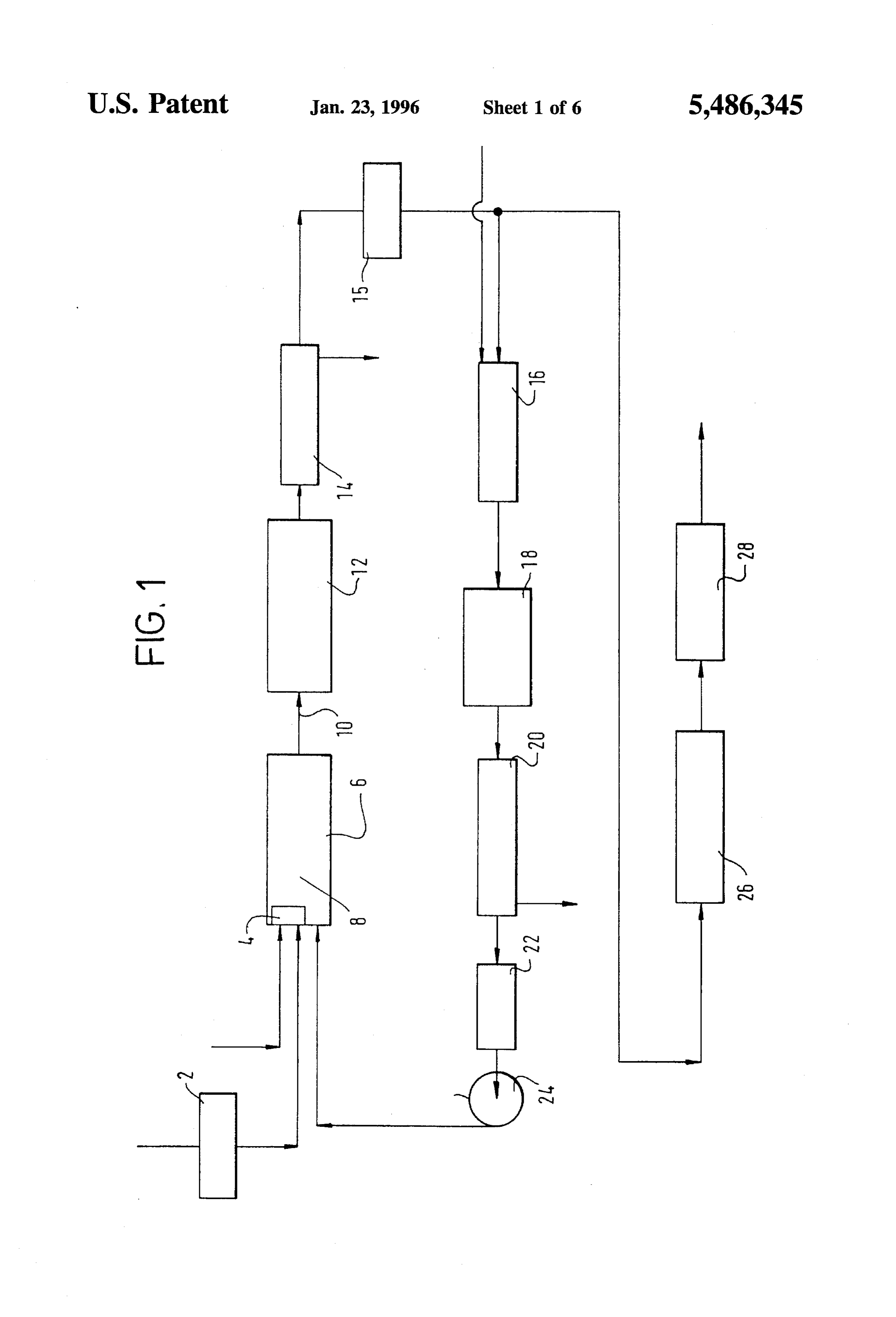
BRIEF DESCRIPTION OF THE DRAWINGS 40 and the outlet 10 of the furnace. Recycled sulphur dioxide, Methods and apparatuses according to the invention will whose formation shall be described below, is introduced now be described by way of example with reference to the directly into the reaction region of the furnace intermediate accompanying drawings, in which: the flame Zone 8 and the outlet 10. The introduction of this FIG. 1 is a schematic flow diagram of a first sulphur 45 hydrogen sulphur dioxide enhances the amount of reaction between recovery plant according to the invention employing just one sulphide and sulphur dioxide that takes place in furnace, the furnace and thus increases the formation of sulphur vapour. The flame 8 is typically operated so as to keep the
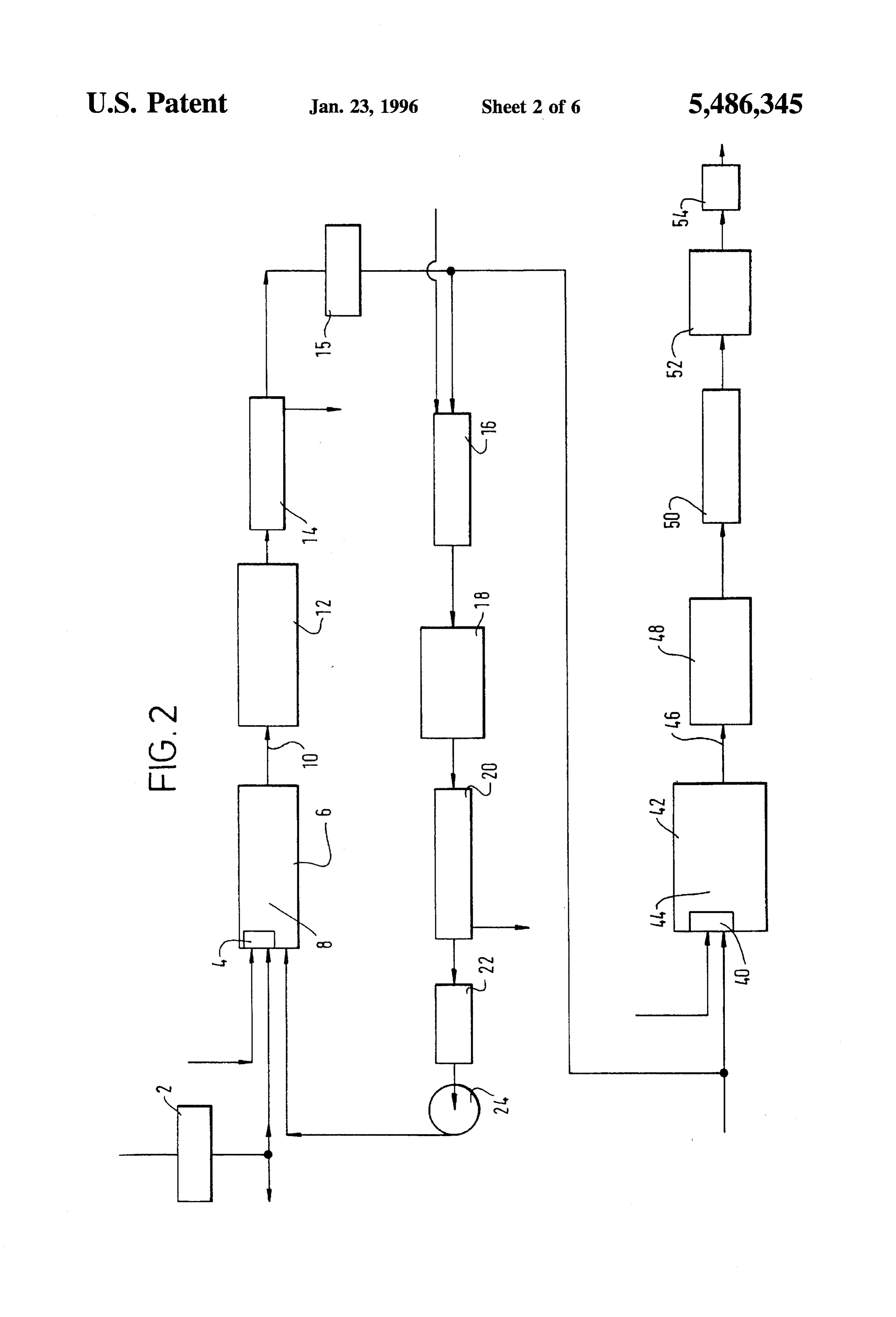
FIG. 2 is a schematic flow diagram of another sulphur refractory lining below a maximum temperature typically in recovery plant according to the invention which employs the range 1400 to 1650° C. depending on the choice of two furnaces; 50 refractory. It is to be appreciated that local temperatures FIG. 3 is a schematic flow diagram of yet another sulphur within the flame 8 well in excess of 1650° C. are nonetheless recovery plant according to the invention employing two created. In addition to the reactions described above, some furnaces. dissociation of hydrogen sulphide into hydrogen and sulphur FIG. 4 is a schematic flow diagram of an incinerator for takes place.
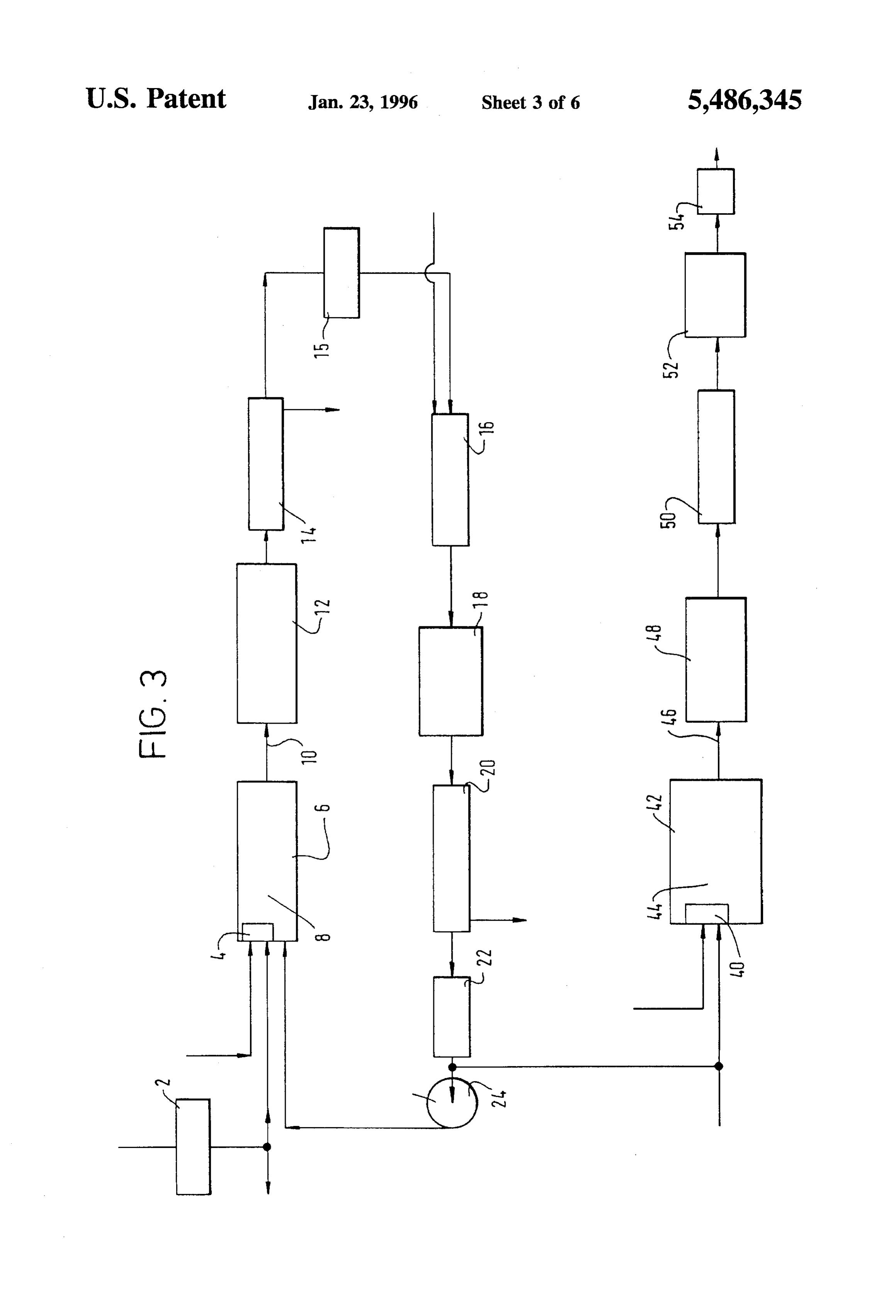
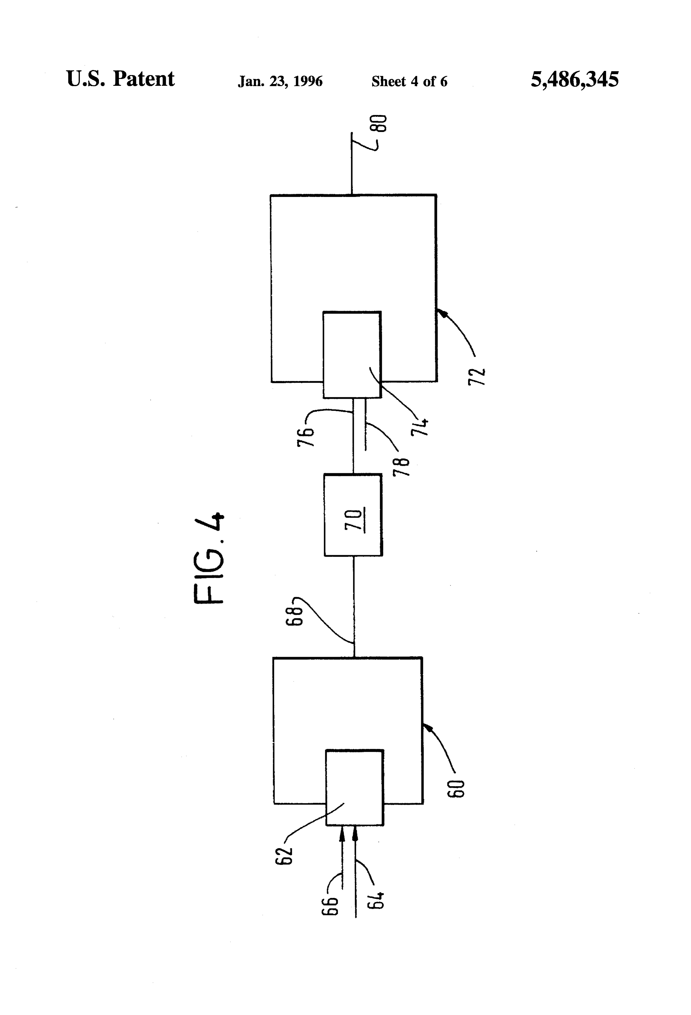
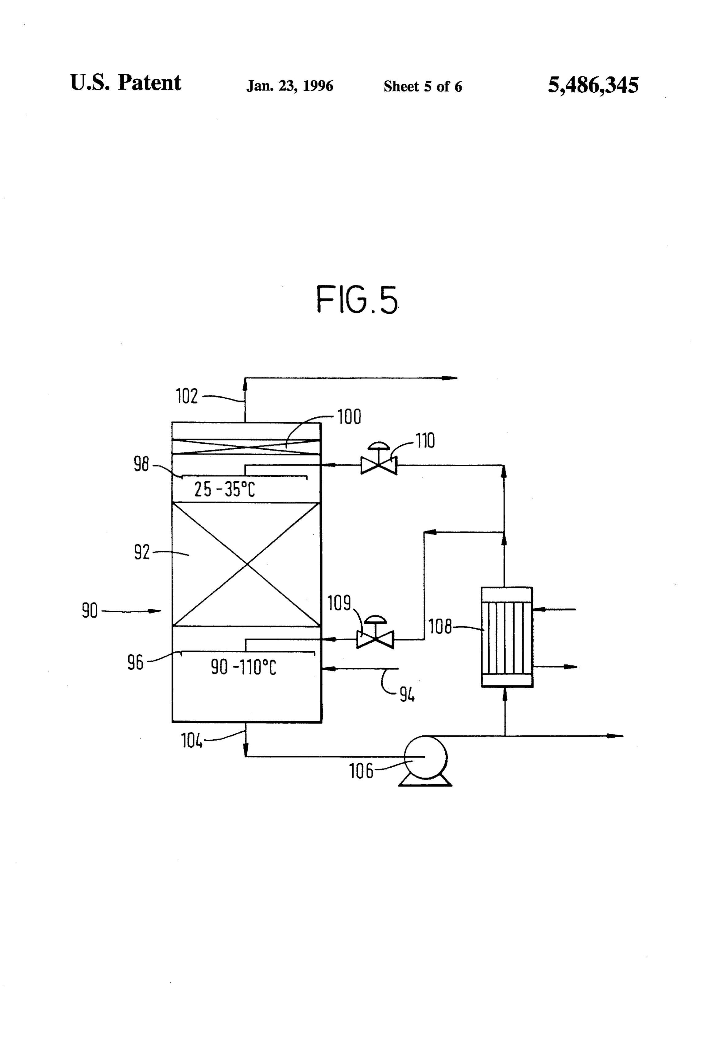
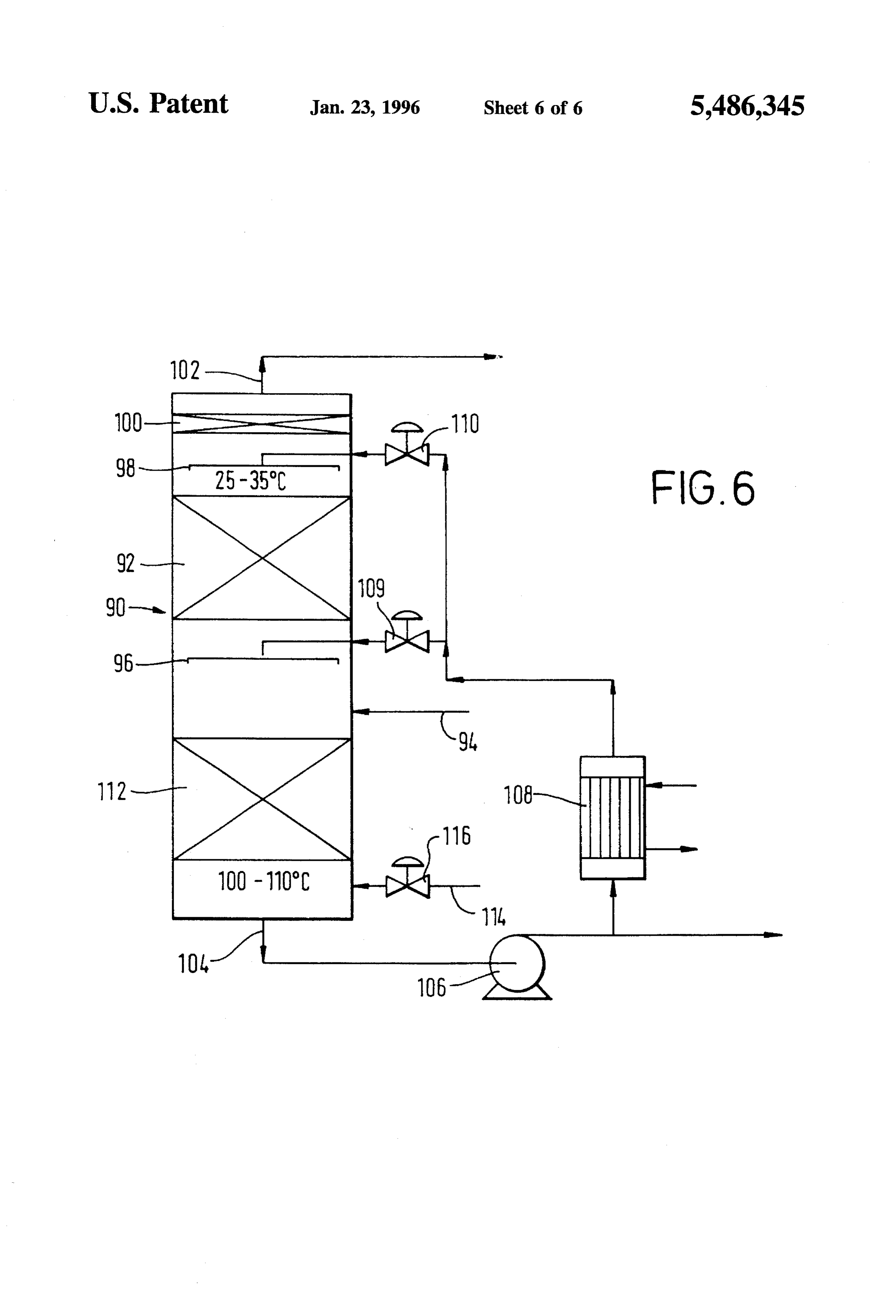
use in the plants shown in FIGS. 1 to 3. 55 The gas stream comprising hydrogen sulphide, sulphur FIG. 5 is a schematic flow diagram of a water separator dioxide, water vapour, sulphur vapour and hydrogen formed for use in the plants shown in FIGS. 1 to 3; and by the dissociation of hydrogen sulphide flows out of the FIG. 6 is a schematic flow diagram of an alternative water furnace 6 through the outlet 10. The gas stream is then separator for use in the plants shown in FIGS. 1 to 3. reduced in temperature typically to a value in the range of 60 300 to 400° C. by passage through a waste heat boiler 12.
In the drawings and the ensuing description, like parts Further cooling of the gas stream and condensation of occurring in different Figures are given the same reference essentially all its sulphur vapour content is performed in a numerals. condenser 14. The liquid sulphur condensate is separated DETALED DESCRIPTION from the gas mixture in the condenser 14 and is typically 65 passed to a sulphur seal pit (not shown). The gas mixture
Referring to FIG. 1 of the drawings, a feed gas stream leaving the condenser 14 typically consists essentially of comprising hydrogen sulphide is heated in a heat exchanger hydrogen sulphide, sulphur dioxide, hydrogen and water
Page 12
vapour and is at a temperature of about 140°C. The ratio of treatment comprising reacting its hydrogen sulphide content hydrogen sulphide to sulphur dioxide in the stream is with its sulphur dioxide content so as to remove substan typically approximately the stoichiometric one of 2:1. tially all the sulphur containing gases therefrom. Accord Accordingly, the ratio of the molar rate of supply of hydro ingly, the second subsidiary gas stream flows through a gen sulphide to the furnace 6 to that of oxygen is well in plurality of catalytic stages shown generally by the reference excess of 2:1. The total content of hydrogen sulphide and numeral 26 in FIG. 1, each comprising, in sequence, first a sulphur vapour in the stream is however less than the content heat exchanger or other heating means (not shown) in which of water vapour. The gas stream may also contain gases the temperature of the gas mixture is raised to a value which do not take part in the reaction. For example, the feed suitable for the catalytic reaction of hydrogen sulphide with gas stream may unavoidably contain carbon dioxide and 10 sulphur dioxide (typically in the order of 190° to 250° C.), nitrogen. Some nitrogen and argon may also be contributed second, a reactor (not shown) comprising beds of catalyst to the gas mixture leaving the furnace 6 by the oxygen-rich (for example, activated alumina) of the reaction between gas. The nitrogen and argon content of the oxygen-rich gas hydrogen sulphide and sulphur dioxide, and, third, a con is therefore preferably kept to a minimum by employing denser (not shown) for separating sulphur from the resulting commercially pure oxygen as the source of the oxygen-rich 15 gas mixture comprising sulphur dioxide, hydrogen sulphide, gas. Nitrogen and carbon dioxide may also be formed by water vapour and sulphur vapour. In the first stage of combustion, for example, of ammonia or hydrocarbon con catalytic reaction, there is no need to provide any heating tained in the feed stream. means in addition to the heater 15, since the heater is The gas stream leaving the condenser 14 may, if desired, effective to raise the temperature of the gas stream to a value be reheated in a heater 15 to a temperature of about 230° C. 20 suitable for the catalytic reaction between hydrogen sulphide and is divided into a first subsidiary stream and a second and sulphur dioxide. Typically, two or three such stages 26, subsidiary stream. The first subsidiary stream is passed to a each comprising heating, catalytic reaction between sulphur reactor or incinerator 16 in which all its hydrogen sulphide dioxide and hydrogen sulphide, and condensation of Sulphur contentis fully oxidised to sulphur dioxide and water vapour vapour are used. The resulting gas stream typically contain by reaction with oxygen-rich gas which is preferably pure 25 ing less than 5% of the sulphur atoms contained in the feed oxygen. The operation of the incinerator 16 is described gas is then passed to a tail gas clean-up unit 28 which may below with reference to FIG. 4 of the accompanying draw be of any conventional kind (e.g. one operating the Scot, ings. The gas mixture leaving the incinerator 16 consists Beavon or Stretford process).
essentially of sulphur dioxide and water vapour. This gas Separation of the water vapour from the first subsidiary stream is typically cooled to a temperature in the order of 30 stream in the condenser 20 has a beneficial effect on the 200° C. in a heat recovery installation 18 such as a heat equilibrium conditions in the furnace 6, as well as reducing exchanger or waste heat boiler. The cooled gas stream is then the overall flow rate of fluid through the catalytic reaction passed into a water vapour separator 20 in which water stages 26. Accordingly, these catalytic stages can be made vapour is removed from the gas stream. Two alternative smaller. The higher effective conversion efficiency in the embodiments of the separator 20 are shown in FIGS. 5 and 35 furnace 6 makes possible the use of two rather than three 6 of the accompanying drawings. Both embodiments stages without any significant loss in overall conversion of employ water to condense the water vapour and are operable hydrogen sulphide to sulphur in comparison to that obtained such that substantially all the water vapour can be condensed in a conventional Claus process with three catalytic stages, whilst avoiding the formation of a liquid effluent containing or for the use of three catalytic stages 26 with a higher such significant quantities of sulphurous or sulphuric acid 40 degree of conversion. Since the flow of gas through the that problems arise in its handling or disposal. catalytic stages is reduced, the tail gas clean-up unit may be It is important to ensure that all the hydrogen sulphide made smaller for a given flow rate of feed gas comprising content of the major subsidiary stream is destroyed by hydrogen sulphide.
oxidation to sulphur dioxide and water vapour in the incin A simplified example of the operation of an apparatus as erator 16 since any residual hydrogen sulphide would con 45 shown in FIG. 1 of the drawings has been calculated and is tinue to react with sulphur dioxide with the result that not set out below. A number of approximations and assumptions only water vapour but also sulphur vapour would be con have been made.
densed in the separator 20, thus requiring the addition of a A feed gas stream comprising 100% by volume of hydro system for separating water from sulphur, gen sulphide is pre-heated in the heat exchanger 2 to a The gas stream leaving the condenser 20 comprises 50 temperature of 500° C. and is introduced into the furnace 6 sulphur dioxide from which substantially all of the water through the burner 4 at a rate of 82 kmol/hr. Pure oxygen is vapour has been separated. The sulphur dioxide does how also fed to the burner 4 at a rate of 23 kmol/hr. All the ever contain small amounts of water vapour and will also oxygen reacts in the flame zone 8 of the furnace 4 with contain some small proportion of oxygen as a result of the hydrogen sulphide. The resulting gas mixture accordingly excess oxygen used in the incinerator 16. This gas stream 55 comprises 66.67 parts by volume of hydrogen sulphide, leaves the separator 20 as a gas saturated in water vapour at 15.33 parts by volume of sulphur dioxide and 15.33 parts per a temperature typically in the range of 25 to 35°C. It is then volume by water vapour. Recycle sulphur dioxide is mixed heated to a higher temperature, say 50° C., by means of with this gas at a rate of 18 kmol. A gas mixture comprising heater 22. This heating step renders the gas mixture less 20 parts per volume of hydrogen sulphide, 10 parts per aggressive to apparatus in which it is handled, particularly 60 volume of sulphur dioxide, 62 parts by volume of water the blades of a fan or blower 24 which is employed to vapour and 35 parts by volume of sulphur vapour (assumed recirculate the gas stream comprising sulphur dioxide to the all to be the dimer S) leaves the furnace C ignoring any furnace 6. It is this gas stream which is the source of the dissociation of hydrogen sulphide that takes place in the sulphur dioxide that is introduced into the furnace 6 inter furnace 4). The gas stream is cooled in the waste heat boiler mediate its flame Zone 8 and its outlet 10. 65 12 and then sulphur vapour is condensed out of the mixture The second subsidiary stream formed by dividing the gas in the condenser 14. The gas stream leaving the condenser stream leaving the condenser 14 is subjected to further 14 is divided into first and second streams. The undivided
Page 13
stream flows at a rate of 92 kmol/hr. The first stream flows vapour leaves the furnace 42 through an outlet 46. The gas at a rate of 55.2 kmol/hr and the second stream at a rate of stream is then cooled typically to a temperature in the order 36.8 kmol/hr. The first stream is passed through the incin of 300° C. in a waste heat boiler 48. The gas stream then erator 16 and its sulphur content is converted by reaction passes through a condenser 50, in which sulphur vapour is with oxygen to sulphur dioxide and water vapour. The water separated therefrom by being condensed, the resulting liquid vapour is condensed in the separator 20 and water is sulphur being passed to a sulphur seal pit (not shown). The recovered at a rate of 49.2 kmol/hr. It is assumed that no gas stream from which the sulphur vapour has been water vapour is added to the gas mixture to control the extracted
Each stage now flows to a plurality of catalytic stages 52.
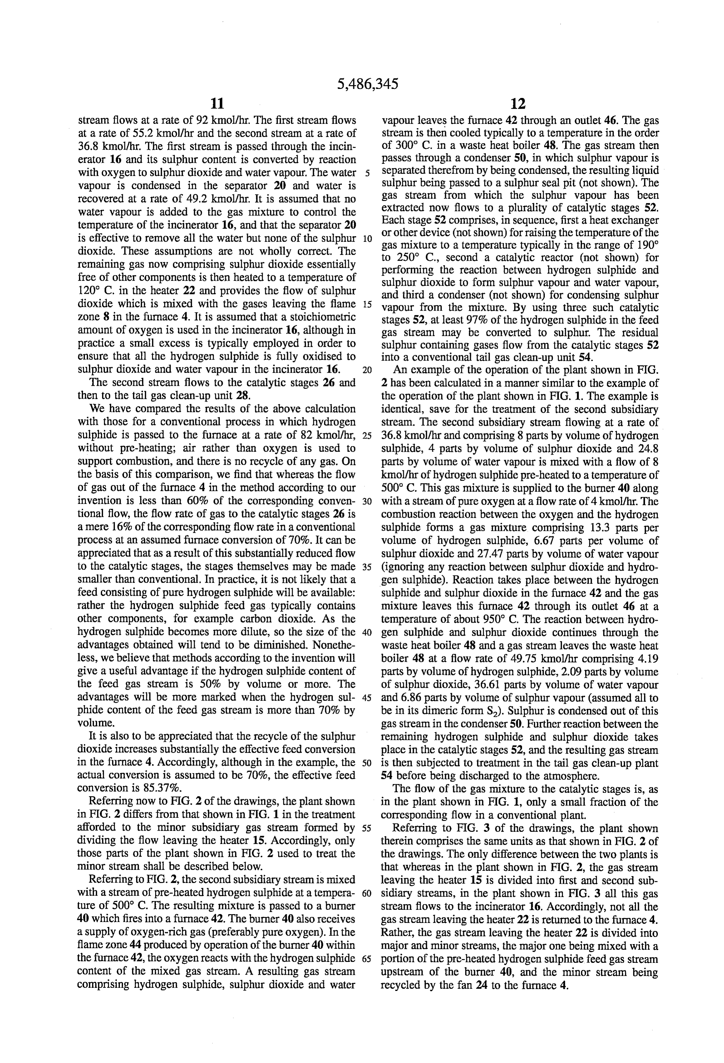
52 comprises, in sequence, first a heat exchanger temperature of the incinerator 16, and that the separator 20 is effective to remove all the water but none of the sulphur 10 or other device (not shown) for raising the temperature of the gas mixture to a temperature typically in the range of 190° dioxide. These assumptions are not wholly correct. The to 250° C., second a catalytic reactor (not shown) for remaining gas now comprising sulphur dioxide essentially performing the reaction between hydrogen sulphide and free of other components is then heated to a temperature of sulphur dioxide to form sulphur vapour and water vapour, 120° C. in the heater 22 and provides the flow of sulphur and third a condenser (not shown) for condensing Sulphur dioxide which is mixed with the gases leaving the flame 15 vapour from the mixture. By using three such catalytic Zone 8 in the furnace 4. It is assumed that a stoichiometric stages 52, at least 97% of the hydrogen sulphide in the feed amount of oxygen is used in the incinerator 16, although in gas stream may be converted to sulphur. The residual practice a small excess is typically employed in order to sulphur containing gases flow from the catalytic stages 52 ensure that all the hydrogen sulphide is fully oxidised to into a conventional tail gas clean-up unit 54. sulphur dioxide and water vapour in the incinerator 16. 20 An example of the operation of the plant shown in FIG. The second stream flows to the catalytic stages 26 and 2 has been calculated in a manner similar to the example of then to the tail gas clean-up unit 28. the operation of the plant shown in FIG. 1. The example is We have compared the results of the above calculation identical, save for the treatment of the second subsidiary with those for a conventional process in which hydrogen stream. The second subsidiary stream flowing at a rate of sulphide is passed to the furnace at a rate of 82 kmol/hr, 25 36.8 kmol/hr and comprising 8 parts by volume of hydrogen without pre-heating; air rather than oxygen is used to sulphide, 4 parts by volume of sulphur dioxide and 24.8 support combustion, and there is no recycle of any gas. On parts by volume of water vapour is mixed with a flow of 8 the basis of this comparison, we find that whereas the flow kmol/hr of hydrogen sulphide pre-heated to a temperature of of gas out of the furnace 4 in the method according to our 500° C. This gas mixture is supplied to the burner 40 along invention is less than 60% of the corresponding conven 30 with a stream of pure oxygen at a flow rate of 4 kmol/hr. The tional flow, the flow rate of gas to the catalytic stages 26 is combustion reaction between the oxygen and the hydrogen a mere 16% of the corresponding flow rate in a conventional sulphide forms a gas mixture comprising 13.3 parts per process at an assumed furnace conversion of 70%. It can be volume of hydrogen sulphide, 6.67 parts per volume of appreciated that as a result of this substantially reduced flow sulphur dioxide and 27.47 parts by volume of water vapour to the catalytic stages, the stages themselves may be made 35 (ignoring any reaction between sulphur dioxide and hydro smaller than conventional. In practice, it is not likely that a gen sulphide). Reaction takes place between the hydrogen feed consisting of pure hydrogen sulphide will be available: sulphide and sulphur dioxide in the furnace 42 and the gas rather the hydrogen sulphide feed gas typically contains mixture leaves this furnace 42 through its outlet 46 at a other components, for example carbon dioxide. As the temperature of about 950° C. The reaction between hydro hydrogen sulphide becomes more dilute, so the size of the 40 gen sulphide and sulphur dioxide continues through the advantages obtained will tend to be diminished. Nonethe waste heat boiler 48 and a gas stream leaves the waste heat less, we believe that methods according to the invention will boiler 48 at a flow rate of 49.75 kmol/hr comprising 4.19 give a useful advantage if the hydrogen sulphide content of parts by volume of hydrogen sulphide, 2.09 parts by volume the feed gas stream is 50% by volume or more. The of sulphur dioxide, 36.61 parts by volume of water vapour advantages will be more marked when the hydrogen sul 45 and 6.86 parts by volume of sulphur vapour (assumed all to phide content of the feed gas stream is more than 70% by be in its dimeric form S2). Sulphur is condensed out of this volume. gas stream in the condenser 50. Further reaction between the It is also to be appreciated that the recycle of the sulphur remaining hydrogen sulphide and sulphur dioxide takes dioxide increases substantially the effective feed conversion place in the catalytic stages 52, and the resulting gas stream in the furnace 4. Accordingly, although in the example, the 50 is then subjected to treatment in the tail gas clean-up plant actual conversion is assumed to be 70%, the effective feed 54 before being discharged to the atmosphere. conversion is 85.37%. The flow of the gas mixture to the catalytic stages is, as Referring now to FIG. 2 of the drawings, the plant shown in the plant shown in FIG. 1, only a small fraction of the in FIG. 2 differs from that shown in FIG. 1 in the treatment corresponding flow in a conventional plant. afforded to the minor subsidiary gas stream formed by 55 Referring to FIG. 3 of the drawings, the plant shown dividing the flow leaving the heater 15. Accordingly, only therein comprises the same units as that shown in FIG. 2 of those parts of the plant shown in FIG. 2 used to treat the the drawings. The only difference between the two plants is minor stream shall be described below. that whereas in the plant shown in FIG. 2, the gas stream Referring to FIG. 2, the second subsidiary stream is mixed leaving the heater 15 is divided into first and second sub with a stream of pre-heated hydrogen sulphide at a tempera 60 sidiary streams, in the plant shown in FIG. 3 all this gas ture of 500° C. The resulting mixture is passed to a burner stream flows to the incinerator 16. Accordingly, not all the 40 which fires into a furnace 42. The burner 40 also receives gas stream leaving the heater 22 is returned to the furnace 4. a supply of oxygen-rich gas (preferably pure oxygen). In the Rather, the gas stream leaving the heater 22 is divided into flame zone 44 produced by operation of the burner 40 within major and minor streams, the major one being mixed with a the furnace 42, the oxygen reacts with the hydrogen sulphide 65 portion of the pre-heated hydrogen sulphide feed gas stream content of the mixed gas stream. A resulting gas stream upstream of the burner 40, and the minor stream being comprising hydrogen sulphide, sulphur dioxide and water recycled by the fan 24 to the furnace 4.
Page 14
The furnace 42 shown in FIG. 3 is however substantially sively cooled and so there is a transfer of water from the gas larger than the corresponding furnace shown in FIG. 2, and phase to the liquid phase. The gas typically passes through it is contemplated that whereas in operation of the plant the top of the packing 92 at a temperature in the range 25 shown in FIG. 2, the vast majority of the feed gas compris to 35° C. and is saturated with water vapour at that tem ing hydrogen sulphide passes to the furnace 4 rather than the perature. The column is provided near its top with a demister furnace 42, in operation of the plant shown in FIG. 3, more 100 so as to disengage droplets of liquid water from the gas. of the hydrogen sulphide feed gas flows to the furnace 42 The resulting gas, relatively free of water vapour in com than to the furnace 4. Accordingly, there is a correspondingly parison to that entering the column 90 through the inlet 94, larger flow of oxygen-rich gas to the furnace 42 than to the passes out of the column through an outlet 102 at its top and furnace 4. 10 flows to the heater 22 shown in each of FIGS. 1 to 3. Referring now to FIG. 4 of the drawings, there is shown Transfer of sulphur dioxide from the gas phase to the a hydrogen sulphide incineration apparatus that may be used liquid phase also takes place as the gas ascends the packing as any of the incinerators 16 shown in FIGS. 1 to 3. The 92. As the liquid phase descends the packing this sulphur dioxide returns to the gas phase as the temperature of the incinerator shown in FIG. 4 comprises a first furnace 60 into liquid progressively increases. Accordingly, the liquid water which a burner 62 fires. The burner 62 has a first inlet 64 for 15 the hydrogen sulphide containing gas mixture and a second dissolvedreaching the bottom of the column 90 is relatively free of inlet 66 which communicate with a source of oxygen-rich the order sulphur of 90° dioxide typically being at a temperature in to 110° C. depending on the operating gas (not shown), preferably pure oxygen. The relative rates pressure of the column 90. (This operating pressure is of supply of oxygen and hydrogen sulphide containing gas mixture to the burner 62 are selected so as to ensure that the 20 typically in the range of 100 to 150 kPa (absolute)). The temperature of the gas mixture leaving the furnace 60 liquid water is withdrawn from the bottom of the column 90 through an outlet 68 does not exceed, say, 1600° C. Accord through an outlet 104 at its bottom by a pump 106. A part of ingly, the rate of supply of oxygen relative to that of the liquid water stream thus withdrawn may be discharged, while the remainder is passed through a heat exchanger 108, hydrogen sulphide is below the stoichiometric value neces sary for complete combustion of the hydrogen sulphide. 25 typicallybyto water, cooled in which it is reduced in temperature
The gas mixture leaving the furnace through the outlet 68 cold water aistemperature then in the range of 20 to 30°C. This returned to the column 90, being the is then cooled in a heat recovery device 70 (e.g. a waste heat boiler) to a temperature a little above that at which sulphur 109 and 110 are operable to control the96relative source of the supply for the distributors and 98. Valves rates of consenses. Accordingly, sulphur formed by reaction supply of coldwater to the respective distributors 96 and 98. between the hydrogen sulphide and sulphur dioxide passes Referring now to FIG. 6 of the drawings, there is shown through the heat recovery device 70 with the other compo 30 a modified water separation apparatus of the kind shown in nents of the gas stream. This gas stream then flows into an FIG. 5. In the apparatus shown in FIG. 6, there is a lower inlet 76 of a second burner 74 that fires into a second furnace 72. The burner 74 has a second inlet 78 for oxygen-rich gas body of packing 112 located intermediate the gas inlet 94 (preferably pure oxygen). The rate of supplying pure oxygen and the bottom of the column 90. Accordingly water com is chosen so as to ensure that there is complete combustion 35 prising through that leaving the packing 92 and that introduced the distributor 96 descends under gravity through of all the hydrogen sulphide and sulphur vapour content of the packing 112. Steam is introduced into the column 90 the gas mixture entering the burner 74. Accordingly, a slight below the packing 112 through an inlet 114. The steam thus stoichiometric excess of oxygen is supplied. A gas mixture ascends the packing 112 and is thereby effective to strip consisting essentially of sulphur dioxide and water vapour residual traces of sulphur dioxide from the water descending leaves the furnace 72 through an outlet 80 typically at a 40 the packing 112. This water leaves the packing 112 at a temperature in the range of 600 to 1000 C. and then passes temperature typically in the range of 100 to 110° C. to the heat recovery unit 18 shown in each of FIGS. 1 to 3. (depending on the operating pressure of the column 90) and Referring now to FIG. 5 of the accompanying drawings, there is shown a first apparatus suitable for use as the water iscontrol withdrawn through the outlet 104 by the pump 106. A flow separator 20 in each of FIGS. 1 to 3. The apparatus comprise 45 rate of valve 116 is provided in the inlet 114 to enable the introduction of steam into the column 90 to be a column 90 containing a structured or random packing 92 controlled.
for effecting intimate contact between the gaseous and liquid In other respects, the operation and construction of the phases. The column has, beneath the packing 92, inlet 94 for apparatus shown in FIG. 6 are identical to those of the the mixture of sulphur dioxide and water vapour that leaves the heat recovery unit 18 shown in each of FIGS. 1 to 3 of apparatus shown in FIG. 5.
The method according to the invention is further illus the accompanying drawings. There is also a cold water 50 trated by the following computer-simulated Examples. distributor 96 located beneath the packing 92 but above the inlet 94. There is thus, in operation, some contact between the water issuing from the distributor 96 and the gas entering EXAMPLE 1. the column 90 from the inlet 94. Although the water dis tributor 96 may be omitted, its operation can typically help 55 A mixture of amine and sour water stripper gases from an to reduce the gas temperature from its inlet temperature of oil refinery is treated by the method according to the about 200° C. to a value in the range 90° to 110° C. and also invention in the plant shown in FIG. 1 of the drawings. The has the advantages of reducing the gas velocity through the mixture is preheated to 500° C. in the heat exchanger 2, and packing 92 and reducing the rate at which water needs to be the recycle stream is heated to 50° C. in the heater 22. The supplied to the top of the packing 92. pressure of the feed gas stream is 55 kPa (gauge) and the A second water distributor 98 is located above the packing 60 outlet temperature of the furnace 6 is calculated to be 1298 92. Cold water is thus in operation caused to flow down C. The results of the simulation are given in Table 1 below. wardly through the packing 92 and come into intimate heat It is assumed that an apparatus as shown in FIG. 4 is used and mass transfer relationship with the sulphur dioxide as the incinerator 16 and an apparatus as shown in FIG. 6 is containing gas mixture that ascends the column 90. As the used as the separator 20. It is further assumed that the water gas flows upwardly through the packing 92 so it is progres condensed in the separator 20 is free of sulphur dioxide.
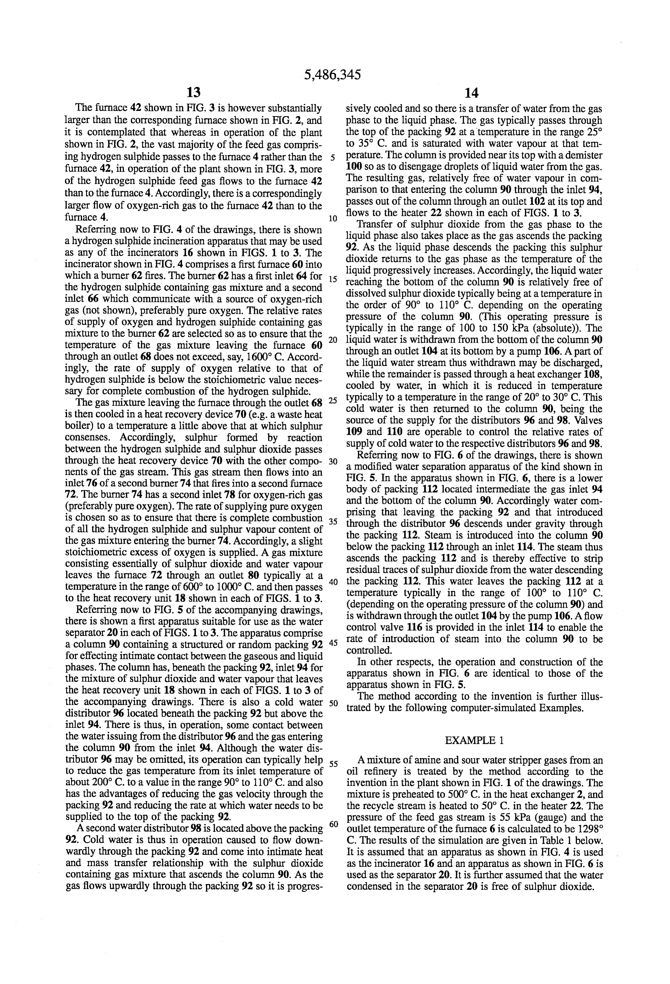
Page 15
TABLE 1
Material flows (kmols/hr) of Streams
A B C D E F G H I J K
H2 12.1 12.1 7.1 5.0
N2 8.0 13.6 13.6 8.0 5.6 8.0
CO 2.8 2.8 1.6 1.2
CO2 3.3 5.2 6.0 6.0 3.5 2.5 5.2
H2S 72.0 16.8 16.8 9.8 7.0
COS 0.1 0,1 0.1 00
SO2 4.8 8.4 8.4 4.9 3.5 4.8
H2O 13.1 1.2 75.0 75.0 43.9 31.1 60.8 59.6
S2 30.8 30.8
Total 100.0 224. 29.7 65.6 134.8 30.8 78.9 55.9 88.8 59.6. 19.7
Referring to Table 1: 20 plant. These calculations assume that thermodynamic equi Stream A is the feed gas entering the burner 4; librium is achieved in the thermal and catalytic stages. Stream B is the oxygen stream entering the burner 4; The results are shown in Table 2 below. Stream C is the recycle stream downstream of the fan 24; TABLE 2 Stream D is the gas stream at the inlet to the sulphur as condenser 14. Thermal 1st Catalytic 2nd Catalytic 3rd Catalytic
Stream E is the gas stream at the outlet for gas from the sulphur condenser 14. Example 85.56 95.9 98.45 99.31 Stream F is the sulphur stream withdrawn from the Air-based 69.36 92.07 97.16 98.35
Stream G is the first subsidiary stream (i.e. that stream passing from the condenser 14 to the incinerator 16).
Stream. His the second subsidiary stream (i.e. that stream EXAMPLE 2 assing from the condenser 14 to the catalytic stages 5. 9. y g 35 An amine feed gas from an oil refinery is treated by the Str I is th t t the outlet of the incinerat method according to the invention in the plant shown in FIG. " 1s the gas stream at the outlet or the 1ncinerator 1 of the drawings. The feed gas stream is preheated to 500 -. C. in the heat exchanger 2, and the recycle stream is heated Stream J is the net water flow condensed in the separator to 50° C. in the heater 22. The pressure of the feed gas 20. stream is 55 kPa (gauge) and the outlet temperature of the Stream K is the oxygen stream supplied to the incinerator furnace 6 is calculated to be 1305° C. The results of the 16. simulation are given in Table 3 below. It is assumed that an A calculation was also made of the effective cumulative apparatus as shown in FIG. 4 is used as the incinerator 16 percentage conversions achieved in the thermal stage (i.e. and an apparatus as shown in FIG. 6 is used as the separator the furnace 6) and the catalytic stages 26 (assumed to be 20. It is further assumed that the water condensed in the three in number) achieved in this example, and a compara- separator 20 is free of sulphur dioxide.
TABLE 3
Material Flows (kmols/hr) of Streams
A B C D E F - G H I J K
H2 11. 11. 5.3 5.8
CO 6.3 6.3 3.0 .3.3
CO2 9.0 9.3 12.7 12.7 6.1 6.6 9.3
H2S 90.0 16.9 16.9 8.1 8.8
COS 0.3 0.3 0.1 0.2
SO2 12.4 8.6 8.6 4.1 4.5 12.4
H2O 0.9 64.9 64.9 31.1 33.8 44.5 43.6
S2 38.3 38.3
O2 25.9 0.5 17.0 Total 100.0 25.9 23.1. 159.1 120.8 38.3 57.8 63.0 66.2, 43.6 17.0
Referring to Table 3, the streams A to K have the same tive calculation was made for a conventional air-based Claus definitions as the respective streams A to K of Table 1.
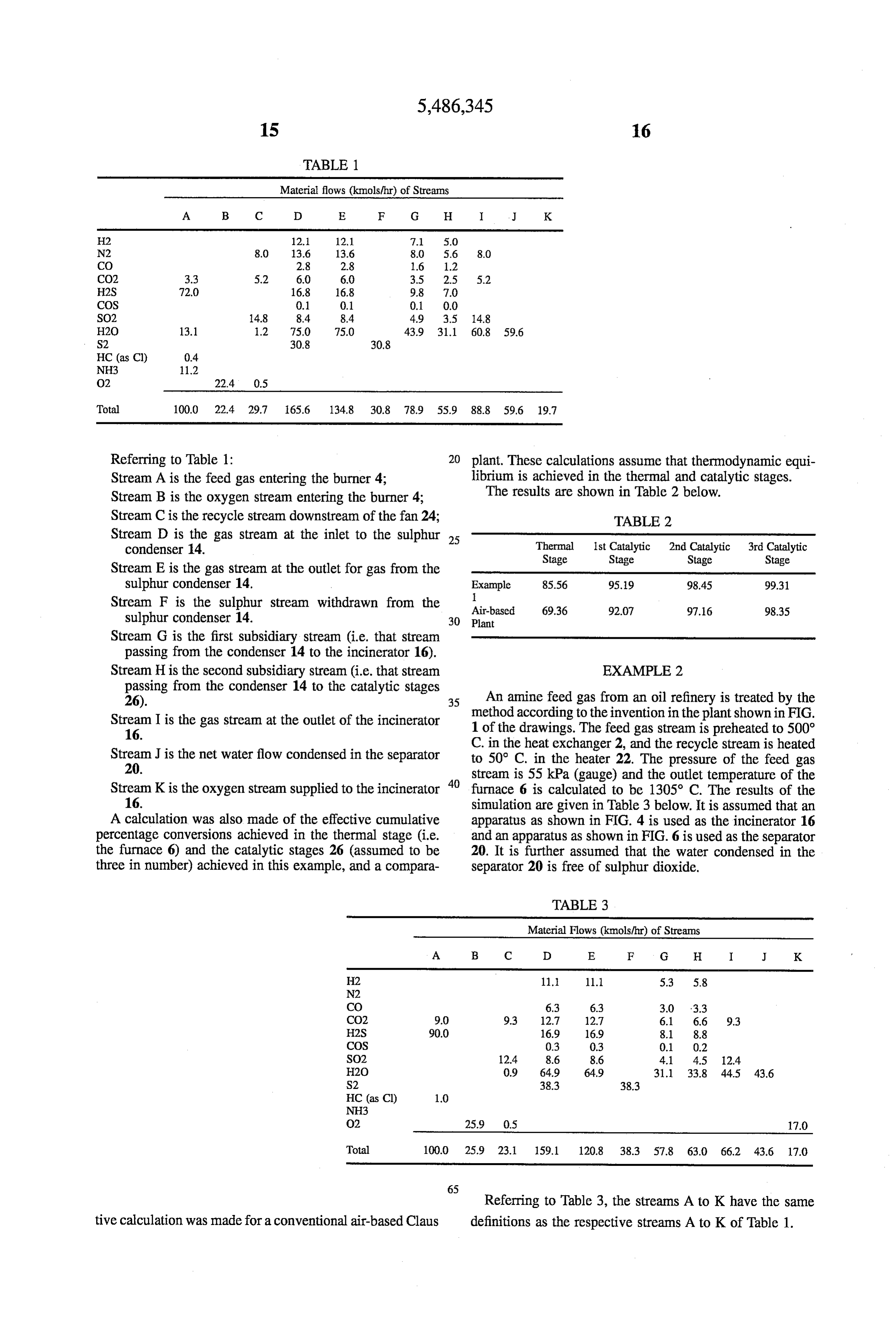
Page 16
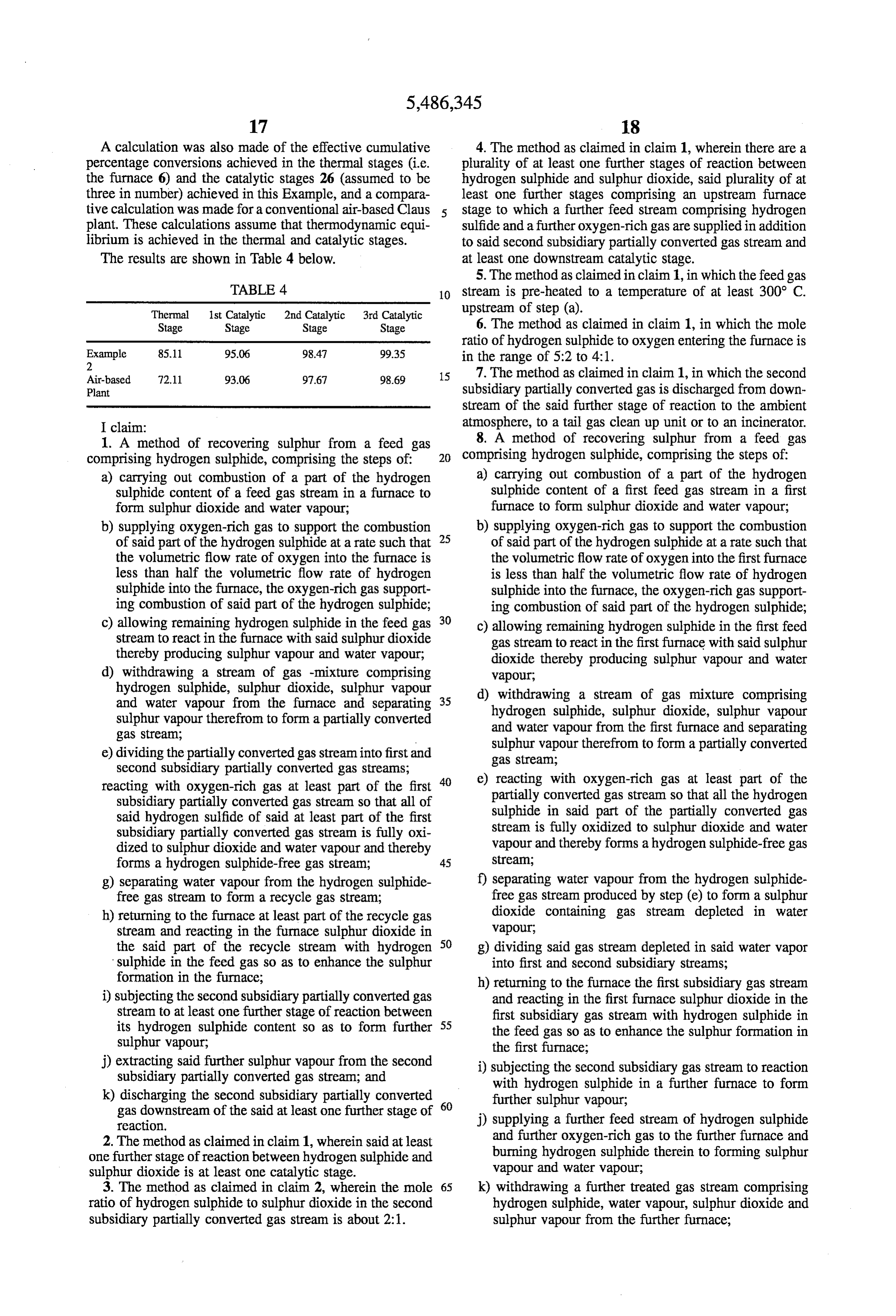
A calculation was also made of the effective cumulative 4. The method as claimed in claim 1, wherein there are a percentage conversions achieved in the thermal stages (i.e. plurality of at least one further stages of reaction between the furnace 6) and the catalytic stages 26 (assumed to be hydrogen sulphide and sulphur dioxide, said plurality of at three in number) achieved in this Example, and a compara least one further stages comprising an upstream furnace tive calculation was made for a conventional air-based Claus stage to which a further feed stream comprising hydrogen plant. These calculations assume that thermodynamic equi sulfide and a further oxygen-rich gas are supplied in addition librium is achieved in the thermal and catalytic stages. to said second subsidiary partially converted gas stream and The results are shown in Table 4 below. at least one downstream catalytic stage. 5. The method as claimed in claim 1, in which the feed gas
TABLE 4 10 stream is pre-heated to a temperature of at least 300° C.
Thermal 1st Catalytic 2nd Catalytic 3rd Catalytic upstream of step (a).
Stage Stage Stage Stage 6. The method as claimed in claim 1, in which the mole ratio of hydrogen sulphide to oxygen entering the furnace is
Example 85.11 95.06 98.47 99.35 in the range of 5:2 to 4:1.
Air-based T2.11 93.06 97.67 98.69 15 7. The method as claimed in claim 1, in which the second Plant subsidiary partially converted gas is discharged from down stream of the said further stage of reaction to the ambient
I claim: atmosphere, to a tail gas clean up unit or to an incinerator. 1. A method of recovering sulphur from a feed gas 8. A method of recovering sulphur from a feed gas comprising hydrogen sulphide, comprising the steps of: 20 comprising hydrogen Sulphide, comprising the steps of: a) carrying out combustion of a part of the hydrogen a) carrying out combustion of a part of the hydrogen sulphide content of a feed gas stream in a furnace to sulphide content of a first feed gas stream in a first form sulphur dioxide and water vapour; furnace to form sulphur dioxide and water vapour; b) supplying oxygen-rich gas to support the combustion 25 b) supplying oxygen-rich gas to support the combustion of said part of the hydrogen sulphide at a rate such that of said part of the hydrogen sulphide at a rate such that the volumetric flow rate of oxygen into the furnace is the volumetric flow rate of oxygen into the first furnace less than half the volumetric flow rate of hydrogen is less than half the volumetric flow rate of hydrogen Sulphide into the furnace, the oxygen-rich gas support sulphide into the furnace, the oxygen-rich gas support ing combustion of said part of the hydrogen sulphide; ing combustion of said part of the hydrogen sulphide; c) allowing remaining hydrogen sulphide in the feed gas 30 c) allowing remaining hydrogen sulphide in the first feed stream to react in the furnace with said sulphur dioxide gas stream to react in the first furnace with said sulphur thereby producing sulphur vapour and water vapour; dioxide thereby producing sulphur vapour and water d) withdrawing a stream of gas -mixture comprising vapour, hydrogen sulphide, sulphur dioxide, sulphur vapour d) withdrawing a stream of gas mixture comprising and water vapour from the furnace and separating 35 hydrogen sulphide, sulphur dioxide, sulphur vapour sulphur vapourtherefrom to form a partially converted and water vapour from the first furnace and separating gas Stream, e) dividing the partially converted gas stream into first and sulphur vapourtherefrom to form a partially converted second subsidiary partially converted gas streams; gas stream;
reacting with oxygen-rich gas at least part of the first 40 e) reacting with oxygen-rich gas at least part of the subsidiary partially converted gas stream so that all of partially converted gas stream so that all the hydrogen said hydrogen sulfide of said at least part of the first sulphide in said part of the partially converted gas subsidiary partially converted gas stream is fully oxi stream is fully oxidized to sulphur dioxide and water dized to sulphur dioxide and water vapour and thereby vapour and thereby forms a hydrogen sulphide-free gas forms a hydrogen sulphide-free gas stream; 45 stream;
g) separating water vapour from the hydrogen sulphide f) separating water vapour from the hydrogen sulphide free gas stream to form a recycle gas stream; free gas stream produced by step (e) to form a sulphur h) returning to the furnace at least part of the recycle gas dioxide containing gas stream depleted in water stream and reacting in the furnace sulphur dioxide in vapour, the said part of the recycle stream with hydrogen 50 g) dividing said gas stream depleted in said water vapor sulphide in the feed gas so as to enhance the sulphur into first and second subsidiary streams; formation in the furnace; h) returning to the furnace the first subsidiary gas stream i) subjecting the second subsidiary partially converted gas and reacting in the first furnace sulphur dioxide in the stream to at least one further stage of reaction between first subsidiary gas stream with hydrogen sulphide in its hydrogen sulphide content so as to form further 55 the feed gas so as to enhance the sulphur formation in Sulphur vapour; the first furnace;
j) extracting said further sulphur vapour from the second i) subjecting the second subsidiary gas stream to reaction subsidiary partially converted gas stream; and with hydrogen sulphide in a further furnace to form k) discharging the second subsidiary partially converted 60 further sulphur vapour;
gas downstream of the said at least one further stage of j) supplying a further feed stream of hydrogen sulphide reaction.
2. The method as claimed in claim 1, wherein said at least and further oxygen-rich gas to the further furnace and one further stage of reaction between hydrogen sulphide and burning hydrogen sulphide therein to forming sulphur sulphur dioxide is at least one catalytic stage. vapour and water vapour; 3. The method as claimed in claim 2, wherein the mole 65 k) withdrawing a further treated gas stream comprising ratio of hydrogen sulphide to sulphur dioxide in the second hydrogen sulphide, water vapour, sulphur dioxide and subsidiary partially converted gas stream is about 2:1. sulphur vapour from the further furnace;
Page 17
l) extracting sulphur vapour from the further treated gas 10. The method as claimed in claim8, in which the further stream to form a sulphur-free gas stream; feed gas stream is preheated to a temperature of at least 300 m) subjecting the sulphur-free gas stream to at least one C.
catalytic stage of reaction between hydrogen sulphide 11. The method as claimed in claim 8, in which the mole and sulphur dioxide, to form yet further sulphur vapour, and ratio of hydrogen sulphide to oxygen entering the first n) extracting the yet further sulphur vapour to form a furnace is in the range of 5:2 to 4:1. residual gas; and 12. The method as claimed in claim 8, in which the o) discharging the residual gas. 10 residual gas is discharged to the ambient atmosphere, to a 9. The method as claimed in claim 8, in which the first tail gas clean up unit or to an incinerator. feed gas stream is preheated to a temperature of at least 300

Provenance
- Collection
- Cited prior art
- Original PDF
- patentimages.storage.googleapis.com →
- Filed
- 1994-08-19
- Pages
- 17
- Method
- pdftotext (the PDF's own text layer) + pdftoppm 300dpi page scans
- Source
- Google Patents bibliographic record
- Granted
- 1996-01-23
- Inventors
- Richard W. Watson; BOC Group Ltd
- Transcribed from
- patentimages.storage.googleapis.com →