patent · US4262739
System for thermal energy storage, space heating and cooling and power conversion
21 April 1981
Page 1 — bibliographic record
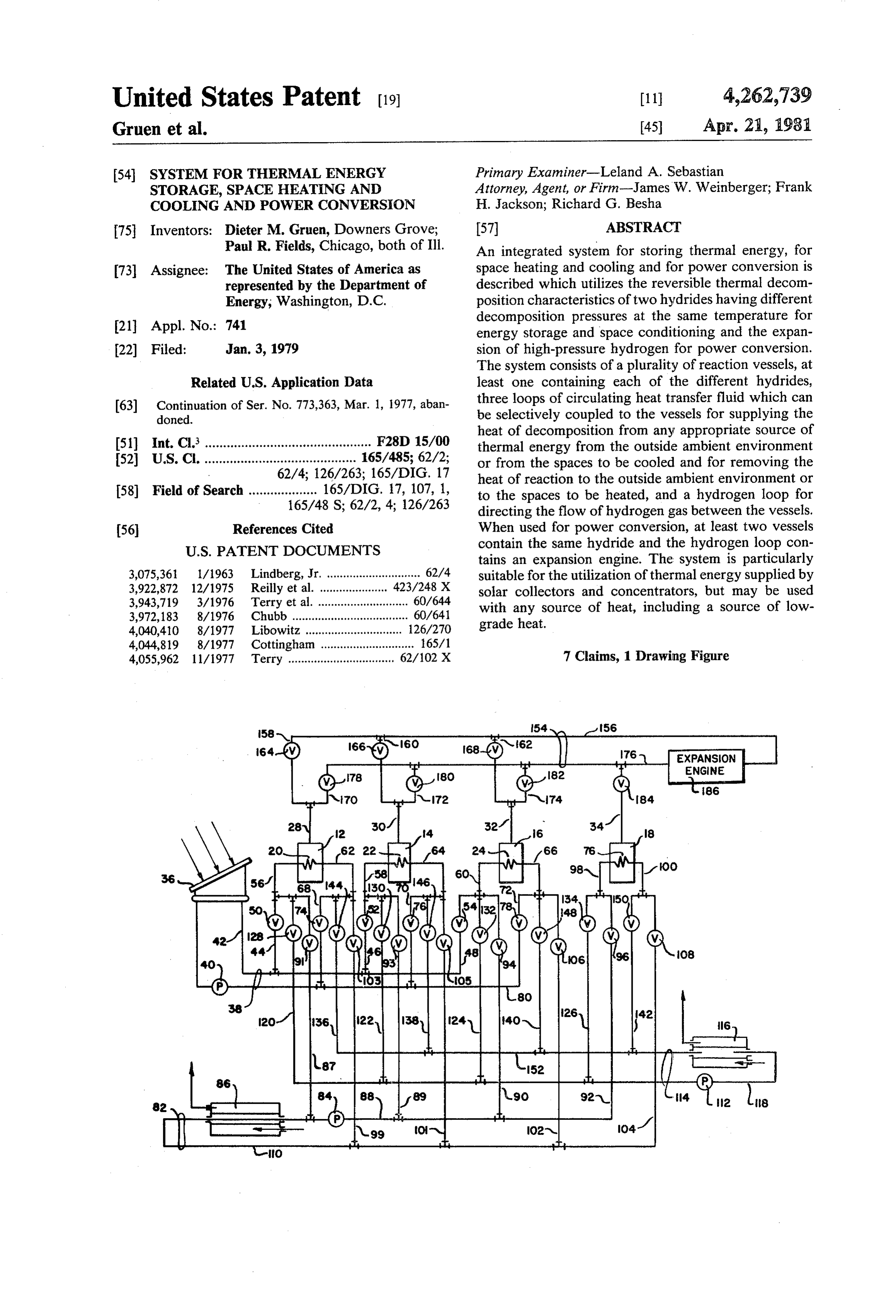
United States Patent (19) 11 4,262,739 Gruen et al. 45 Apr. 21, 1981 54 SYSTEM FORTHERMAL ENERGY Primary Examiner-Leland A. Sebastian STORAGE, SPACE HEATING AND Attorney, Agent, or Firm-James W. Weinberger; Frank COOLNG AND POWER CONVERSION H. Jackson; Richard G. Besha 75 Inventors: Dieter M. Gruen, Downers Grove; 57 ABSTRACT Paul R. Fields, Chicago, both of Ill. An integrated system for storing thermal energy, for 73 Assignee: The United States of America as space heating and cooling and for power conversion is represented by the Department of described which utilizes the reversible thermal decom Energy, Washington, D.C. position characteristics of two hydrides having different decomposition pressures at the same temperature for 21 Appl. No.: 741 energy storage and space conditioning and the expan 22 Filed: Jan. 3, 1979 sion of high-pressure hydrogen for power conversion. The system consists of a plurality of reaction vessels, at
Related U.S. Application Data least one containing each of the different hydrides, 63) Continuation of Ser. No. 773,363, Mar. 1, 1977, aban three loops of circulating heat transfer fluid which can doned. be selectively coupled to the vessels for supplying the heat of decomposition from any appropriate source of 51) Int. Cl. .............................................. F28D 15/00 thermal energy from the outside ambient environment 52 U.S. C. .......................................... 165/485; 62/2; or from the spaces to be cooled and for removing the 62/4; 126/263; 165/DIG. 17 heat of reaction to the outside ambient environment or 58) Field of Search ................... 165/DIG. 17, 107, 1, to the spaces to be heated, and a hydrogen loop for 165/48 S; 62/2, 4, 126/263 directing the flow of hydrogen gas between the vessels.
56 References Cited When used for power conversion, at least two vessels
tains an expansion engine. The system is particularly 3,075,361 1/1963 Lindberg, Jr. ............................. 62/4 suitable for the utilization of thermal energy supplied by 3,922,872 12/1975 Reilly et al. ... ... 423/248 X solar collectors and concentrators, but may be used 3,943,719 3/1976 Terry et al............................. 60/644 with any source of heat, including a source of low 3,972,183 8/1976 Chubb .................................... 60/641 grade heat.
4,040,410 8/1977 Libowitz .............................. 126/270 4,044,819 8/1977 Cottingham ............................. 165/1 4,055,962 11/1977 Terry ................................. 62/102 X 7 Claims, 1 Drawing Figure
loes
Page 2
Drawing sheet — no readable text.
Page 3
ing and cooling in addition to energy conversion is
SYSTEM FORTHERMAL ENERGY STORAGE, disclosed in U.S. Pat. No. 3,943,719, issued Mar. 16, SPACE HEATING AND COOLNG AND POWER 1976. The described system produces high-pressure CONVERSION hydrogen by heating a metal hydride while retaining it 5 at constant volume and generating power by expanding
CONTRACTUAL ORIGIN OF THE INVENTION the compressed gas through a turbine or similar device. The invention described herein was made in the Thermal energy is recovered from the hot hydrogen gas course of, or under, a contract with the UNITED before it is expanded, and refrigeration is supplied by
STATES ENERGY RESEARCH AND DEVELOP
using the expanded-and cold-hydrogen to absorb
MENT ADMINISTRATION. heat from a heat exchange fluid. However, the recovery This is a continuation of application Ser. No. 773,363, of heat and refrigeration by this method is neither effi filed Mar. 1, 1977 now abandoned. cient nor effective for either space heating or cooling BACKGROUND OF THE INVENTION because it utilizes only the heat capacity of hydrogen gas.
This invention relates to a system for storing and 5 utilizing thermal energy. More specifically, this inven SUMMARY OF THE INVENTION tion relates to an integrated system for storing thermal energy, particularly low-grade thermal energy, and useWewith have invented an integrated system suitable for any thermal energy source including low utilizing the thermal energy for space heating and cool grade thermal energy sources, which provides thermal ing and for power generation. 20 energy storage, space heating and cooling and power
Soaring demands for fossil energy coupled with conversion and which operates in part on a chemical dwindling supplies have stimulated a search for alterna tive, particularly renewable, sources of energy. It is heat pump principle. The system, broadly described, well recognized that second law energy utilization effi ing a heatof exchanger, consists a plurality of reaction vessels, each contain a hydrogen gas outlet and a hy ciencies are very low (less than about 10%) for fissile or 25 dride fossil fuels used directly or in the form of electricity in hydride by reaction withmaterial or a hydridable capable of forming a hydrogen at a low tempera normal space heating and cooling applications. Since ture and pressure and thermally decomposing at a about 25% of the total energy consumption in the higher temperature to release hydrogen, a first vessel United States is for these purposes, an incentive exists for the utilization of lower grade heat sources better 30 containing a first hydride or hydridable material and a matched thermodynamically for space heating and second vessel containing a second hydridable material, cooling, since second law efficiencies would be much a source of thermal energy connected with the heat higher. exchanger in the first vessel for selectively heating the A number of sources of low-grade heat, i.e. tempera first hydride to decomposition temperature, thereby tures up to about 150 C., such as reject heat from cen 35 releasing hydrogen, a conduit between the gas outlets in tral power stations, either fossil or nuclear fueled, geo the first and second vessels for directing the flow of thermal energy and particularly solar energy, are in hydrogen between the vessels, waste heat transfer principle very well adapted to these applications. How means connected to the heat exchanger of the second ever, the successful use of energy from any of these pressure vessel for selectively removing waste heat of sources, particularly for space heating and cooling, reaction from the vessel during hydride formation and involves the storage of thermal energy. The intermit expelling the heat to the outside environment and for tent availability of solar radiation in particular requires absorbing heat from the outside environment for sup the storage of energy for use at times when solar radia plying heat of decomposition to the vessel for hydride tion is not available. Traditional methods for storage of decomposition, space heat transfer means connected to heat depend on heat capacity or phase change effects. 45 the heat exchangers in both vessels for selectively re Although water possesses a high specific heat, it has a moving the heat of reaction from the vessels during low volumetric energy storage capacity and requires hydride formation and for supplying heat of decomposi insulated holding tanks. Pebble beds are inexpensive but tion to the vessels during hydride decomposition and have the same drawbacks as water with a much lower heat heat capacity. Salt hydration-dehydration equilibria 50 fer means recovery means connected to the space heat trans have a tendency toward supersaturation after many for space heating for recovering heat from the transfer means cycles, and stratification interferes with reversibility. and for supplying heat to the transfer means for space
The use of hydrogen which can react exothermally two reaction vessels contain cooling. For power conversion, at least with some intermetallic compounds to form decompos relatively high decompositiona second hydride having a pressure at the tempera able hydrides has been suggested as a form of thermal 55 energy storage. One such method and apparatus for ture available from the thermal energy source, the storing thermal energy and for recovering the stored source of thermal energy is connected to the heat ex energy for space heating using metal hydrides is de changer in both vessels for selectively heating the hy scribed in U.S. patent application Ser. No. 605,960, filed dride to decomposition temperature, the waste heat Aug. 19, 1975 and now abandoned. transfer means is coupled to the heat exchanger in both Equally important with the ability to provide space vessels for selectively removing the heat of reaction, heating in many parts of the country if the ability to also and the hydrogen conduit contains an expansion engine cool these same spaces. Particularly useful would be a whereby high-pressure hydrogen released by the de single system which could provide total space air condi composition of the hydride in one vessel is expanded in tioning (both heating and cooling) using a source of 65 the engine producing energy and the expanded gas is low-grade thermal energy, since a large fraction of the directed to the second vessel.
power consumed today is for refrigeration or space It may be noted that using the heat of reaction, as in cooling. One such system which can provide both heat the present invention, is at least an order of magnitude
Page 4
more effective than relying on the heat capacity of 120, 122, 124 and 26, controlled by valves 128, 30, 132 hydrogen gas for heating and cooling purposes. and 134, respectively, to branch conduits 56,58, 60 and As used herein, the word "hydride' or phrase "hydri 98 to the heat exchange loops 20 to 26 in vessels 12 to dable material' are interchangeable since the particular 18, respectively, where the fluid is either heated by hydrogen-to-metal ratio of the material present in each 5 absorbing exothermically generated heat of reaction or vessel will depend upon the particular point in the hy is cooled for refrigeration and space cooling by giving dride-dehydride cycle being described. up endothermic heat of decomposition. The fluid is It is therefore the object of the invention to provide returned through branch return conduits 62, 64, 66 and an integrated system for storing energy, for providing 100 to space heat return conduits 136, 138, 140 and 142, space heating and cooling and for generating power 10 controlled by valves 144, 146, 148 and 150, to outlet which can utilize thermal energy from any source in manifold 152.
cluding low-grade heat sources. The flow of hydrogen gas is selectively directed be BRIEF DESCRIPTION OF THE DRAWING tween the reaction vessels by hydrogen loop 154, hav ing an inlet manifold 156 connected to one end of short
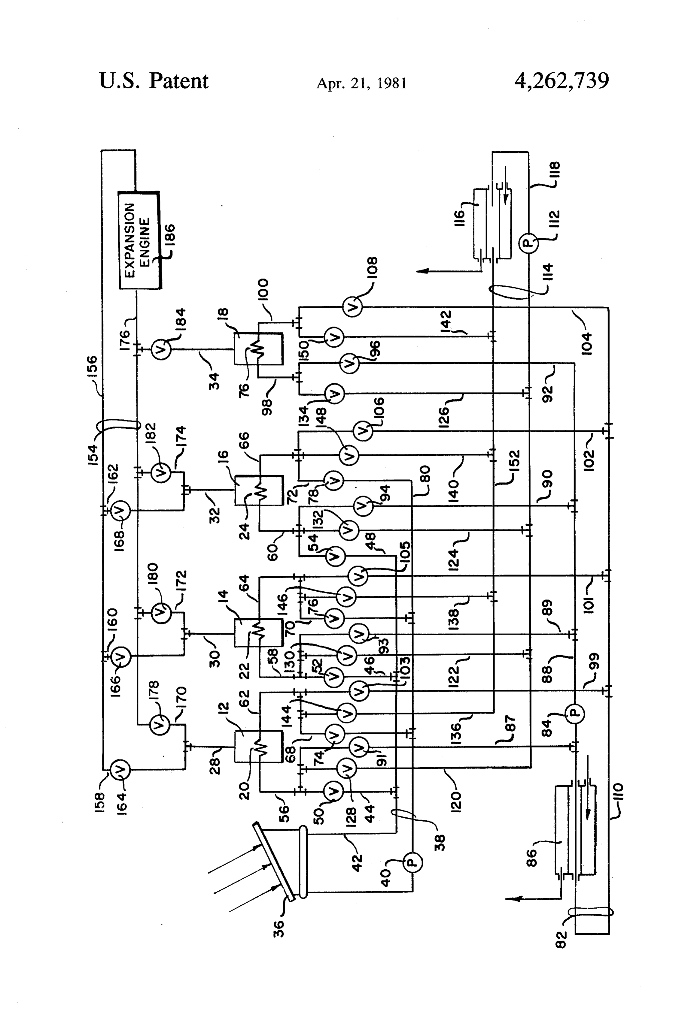
The single FIGURE is a schematic flow diagram of 15 gas inlet conduits 158, 160 and 162, controlled by valves the apparatus of the invention showing a solar energy 164, 166 and 168 which are further connected to short collector as the source of low-grade thermal energy. gas conduits 28, 30 and 32 of vessels 12, 14 and 16, DETAILEED DESCRIPTION OF THE respectively. Gas return conduits 170, 172 and 174 also
connect at one end to conduits 28, 30 and 32 and at the other end to outlet manifold 176 and are each controlled
Referring now to the drawing, the system of the by valves 178, 180 and 182, respectively. Short gas invention as shown consists of four reaction vessels 12, conduit 34 contains control valve 184 and connects 14, 16 and 18, each vessel containing a heat exchange loop 20, 22, 24 and 26 and a short gas conduit 28, 30, 32 directly to outlet manifold 176 which also contains an expansion engine 186 to complete the apparatus.
and 34, respectively. The heat exchange loops may be 25 The choice of hydrides which may be used with the either in or around the vessels. Vessels 12 and 14 con apparatus of the invention will depend primarily upon tain a first hydride or hydridable material capable of the temperature which is available from the source of reacting with hydrogen to form a hydride having a thermal energy, to decompose the first hydrides. Thus, decomposition pressure of from about 8 to 12 atmo for space heating and cooling purposes, the first hyrdide spheres at 100 to 130° C. and 0.1 to 0.5 at 30° to 50° C., must be capable of decomposing at the
vessel 18 contains a second hydride having a decompo available from the source of thermal energytemperature with suffi sition pressure of about 20 to 50 atmospheres at 100 to cient pressure to react with the second hydridable mate 130° C. and 1-7 atmospheres at 10 to 50° C. and vessel rial exothermically to produce a temperature adequate 16 may contain either the first or second hydride. Ther mal energy for hydride decomposition supplied by solar 35 for space heating purposes, and whose hydrogen de energy collector 36 is transferred to a heat transfer fluid is lower thanpressure composition the at the space heating temperature decomposition pressure of the second in heating loop 38 and circulated by pump 40. The fluid, hydride at the low temperature available at 100 to 130 C., is supplied by inlet manifold 42 selec side ambient environment for providingfrom the out tively through heat inlet conduits 44, 46 and 48, con decomposition. For example, temperaturestheavailable heat of trolled by inlet valves 50, 52 and 54, through branch from present solar energy collectors can range from conduits 56, 58 and 60 to heat exchange loops 20, 22 and about 100 to 150° C., while higher temperatures may be 24 in vessels 12-16, respectively. The fluid returns through branch return conduits 62, 64 and 66 and heat available from other sources. An exothermic reaction temperature of from 40' to 60° C. is sufficient for space outlet conduits 68, 70 and 72 controlled by valves 74,76 heating and 78 to heating loop return manifold 80. 45 purposes while about 0° C. outside ambient Waste heat of reaction produced during hydride for temperature is generally available for supplying heat of mation is removed from the vessels and heat of decom decomposition and which will also determine the refrig position is supplied by a heat transfer fluid circulating in eration temperature available for space cooling. waste heat transfer loop 82 by pump 84. The fluid is at The combination of CaNisha as the first hydride with outside ambient temperature by passing through a heat 50 LaNishes as the second hydride has been found success exchanger 86 located in the outdoor environment and is ful, as has the use of Canish4 as the first hydride with supplied through inlet manifold 88 selectively through (cerium free) MmNishis where (cerium free) Mm is waste heat inlet conduits 87, 89,90 and 92, controlled by mischmetal, a mixture of rare earth metals having the inlet valves 91, 93, 94 and 96, through branch conduits approximate composition La 77%, Nd, 16%, Pr 5%, 56,58, 60 and 98 to exchange loops 20 to 26 in vessels 17 55 other lanthanide metals 2%. For example, Canish4 to 18, respectively. The fluid returns through branch decomposes at 130 C, with 12 atmospheres pressure return conduits 62,64, 66 and 100 and return waste heat while the hydrogen combines with LaNis at 50 C. and outlet conduits 99, 101, 102 and 104, controlled by 7 atmospheres. The LaNisha will then decompose at valves 103, 105, 106 and 108, respectively, to branch 10 C. at 1 atmosphere, while the hydrogen reforms return manifold 10. 60 CaNisha 50° C. and 0.5 atmosphere. Heating and refrigeration are supplied to the spaces For power conversion, a hydride which decomposes to be air conditioned by a heat transfer fluid circulated at the available decomposition temperature with a rela by pump 112 in space heat transfer loop 114 and by heat tively high pressure is preferred, such as LaNishi, exchanger 116 which may be physically located in the which decomposes at 140° C. at 50 atmospheres and spaces to be air conditioned or connected with such 65 recombines at 35° C. at 4.9 atmospheres. spaces by some additional means of heat transfer such as The energy conversion device may be any sort of air or water. The fluid in loop 114 is supplied through mechanical device which can convert or use the inter inlet manifold 118 selectively through inlet conduits nal energy from pressurized hydrogen gas to perform
Page 5
mechanical energy by expansion, such as a turbine or transfer fluid follows the same path in both the heat piston engine. rejection and thermal energy recovery modes. The following examples of thermal energy storage, As the hydrides in vessels 16 and 18 are decomposed space heating and cooling and power conversion are to a hydridable metal and hydrogen, the flow of the gas given using CaNisha as the first hydride and LaNishes is directed via the various gas iniet and outlet conduits as the second hydride. LaNishes is used for the power and hydrogen loop 154 to the first hydridable metal in conversion. vessels 12 and 14 where it recombines with the metal to Thermal energy is stored in the system by opening form the hydride giving up the heat of reaction at 50 C. inlet valves 50 and 52 and outlet valves 74 and 76. Solar This heat is recovered from the vessels by opening inlet valves 128 and 130, outlet valves 144 and 146, and circu energy impinging on solar collector 36 is absorbed by 10 lating the heat transfer fluid in loop 38, heated to 100 to 130 the heat exchange fluid in the heat transfer loop C. and cirilated via heat inlet conduits 44 and 46 and through conduits 120 and 122 and branch conduits 56 branch conduits 56 and 58 to heat exchange loops 20 and 58 to heat exchange loops 20 and 22, the fluid re turning through branch return conduits 62 and 64 and and 22 in vessels 12 and 14, respectively, each contain 15 space heat return conduits 136 and 138 to return mani ing the first hydride. The heat exchange fluid returns fold which directs the fluid to space heat exchanger 16. via branch return conduits 62 and 64 and heat outlet conduits 68 and 70 to the return manifold 80 to com Here the heat is removed from the circulating fluid and plete the heating loop. As the hydride is heated, it de recovered for space heating.
For space cooling purposes, thermal energy is first composes, releases hydrogen gas at about 12 atmo 20 stored spheres pressure which is then transferred via hydrogen and 18inasthe form of chemical bond energy in vessels 16 hereinbefore described for space heating, the loop 154 to the second hydridable metals in vessels 16 heat of reaction in vessels 16 and 18 being removed and and 18. This may be accomplished by opening valves exhausted to the outside ambient temperature via heat 164 and 168 and directing the hydrogen from vessel 12 exchanger 86, also as previously described. Refrigera through short gas conduit 28, gas inlet conduit 158 and 25 tion is provided for space cooling by decomposing the inlet manifold 156 to gas inlet conduit 162 and short gas hydrides in vessels 16 and 18 with heat provided by conduit 32 to vessel 16, while by opening valves 18 and space heat transfer loop 114 since the second hydride 184, gas from vessel 14 may be directed via conduits 30 will decompose at about 1 atmosphere at about 10 C. and 172 and outlet manifold 176 to conduit 34 and vessel 18 to combine with the hydridable metal, forming the 30 As the heat is absorbed by the endothermic reaction, the fluid in the loop cools to 10°C. which, as it circulates to second hydride. As the hydride is formed, heat of reac the inside heat exchanger 116, can be used as refrigera tion of about 50° C. is produced and must be removed tion to provide for space cooling. The hydrogen gas for the reaction to go to completion. If recovery of the liberated by the decomposition of the hydrides is di heat from the exothermic reaction is desirable for space rected to the hydridable metals in vessels 12 and 14 heating purposes, inlet valves 132 and 134 and outlet 35 where it recombines with the hydridable metals at about valves 148 and 150 are all opened. Heat exchange fluid 35' C. to reform the hydride. The heat of reaction is circulating in the inlet manifold 118 of space heat trans removed by vessels 12 and 14 by circulating the heat fer loop thus flows through inlet conduits 124 and 126, transfer fluid from the waste heat transfer loop through through branch conduits 60 and 98 to heat exchange the vessels, the heat being exhausted to the outside loops 24 and 26 in vessels 16 and 18 where the heat of 40 ambient environment through outside heat exchanger reaction is absorbed by the fluid, returning via branch 86.
return conduits 66 and 18 and space heat return con As hereinbefore described, the transfer of heat and duits 140 and 142 to space heat transfer loop 114. The hydrogen has taken place simultaneously between ves heat is recovered from the fluid as it passes through sels 12 and 14 and vessels 16 and 8. It is obvious that it indoor heat exchanger 116 located so that the heat re 45 may be desirable to operate the vessels sequentially, i.e. covered therefrom is usable for space heating. to be transferring hydrogen from vessel 12 to vessel 16 If the heat of reaction from vessels 16 and 18 is not for energy storage while at the same time hydrogen is required for space heating, it must be exhausted to the being transferred from vessel 18 to vessel 14 for either outside ambient environment by opening inlet valves 94 space heating or for space cooling. This is the preferred and 96 and outlet valves 106 and 108 and passing the 50 method of operation since it provides a means of contin heat exchange fluid circulating in waste heat loop from uous cooling.
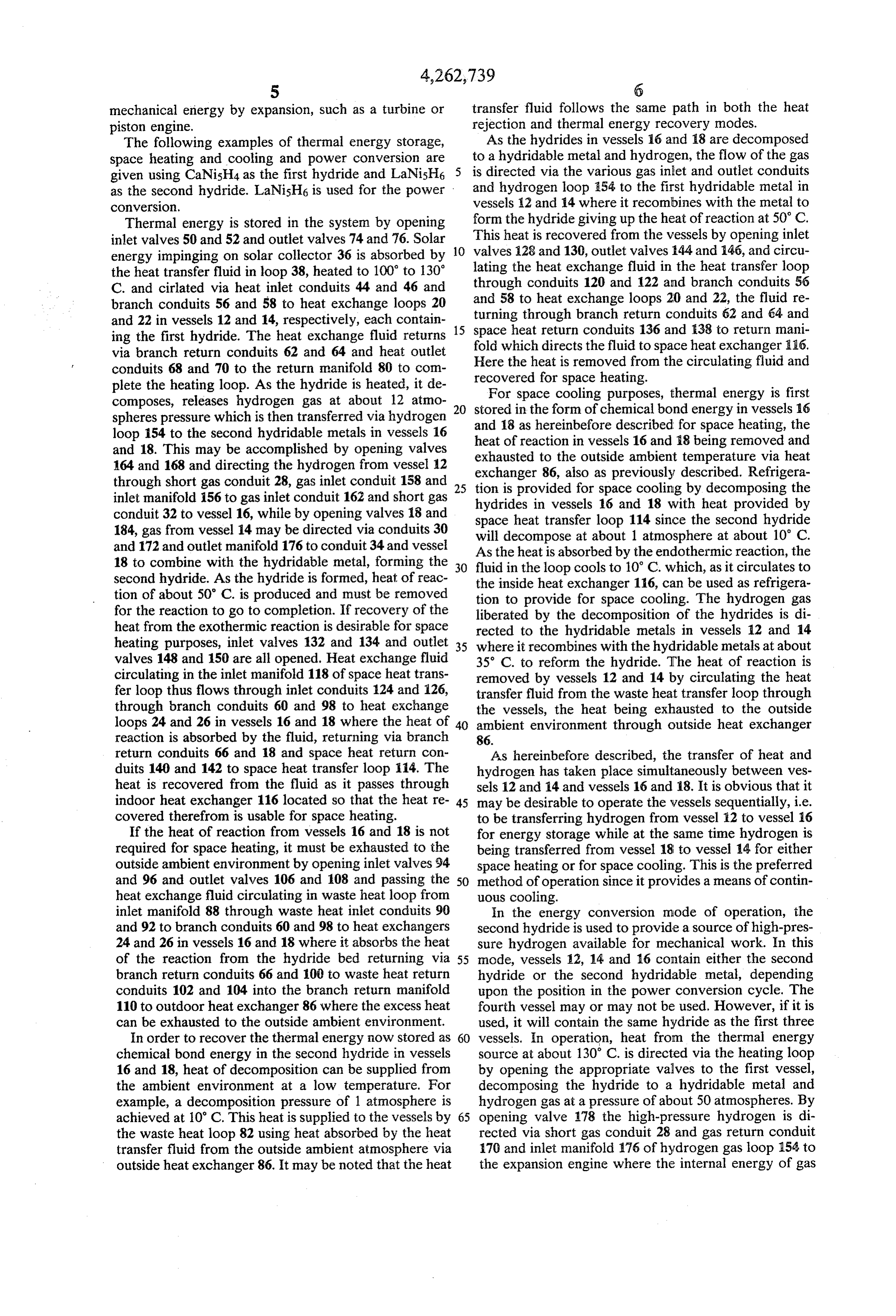
inlet manifold 88 through waste heat inlet conduits 90 in the energy conversion mode of operation, the and 92 to branch conduits 60 and 98 to heat exchangers second hydride is used to provide a source of high-pres 24 and 26 in vessels 16 and 18 where it absorbs the heat sure hydrogen available for mechanical work. In this of the reaction from the hydride bed returning via 55 mode, vessels 12, 14 and 16 contain either the second branch return conduits 66 and 100 to waste heat return hydride or the second hydridable metal, depending conduits 102 and 104 into the branch return manifold upon the position in the power conversion cycle. The 110 to outdoor heat exchanger 86 where the excess heat fourth vessel may or may not be used. However, if it is can be exhausted to the outside ambient environment. used, it will contain the same hydride as the first three In order to recover the thermal energy now stored as 60 vessels. In operation, heat from the thermal energy chemical bond energy in the second hydride in vessels source at about 130° C. is directed via the heating loop 16 and 18, heat of decomposition can be supplied from by opening the appropriate valves to the first vessel, the ambient environment at a low temperature. For decomposing the hydride to a hydridable metal and example, a decomposition pressure of 1 atmosphere is hydrogen gas at a pressure of about 50 atmospheres. By achieved at 10 C. This heat is supplied to the vessels by 65 opening valve 178 the high-pressure hydrogen is di the waste heat loop 82 using heat absorbed by the heat rected via short gas conduit 28 and gas return conduit transfer fluid from the outside ambient atmosphere via 170 and inlet manifold 176 of hydrogen gas loop 154 to outside heat exchanger 86. It may be noted that the heat the expansion engine where the internal energy of gas
Page 6
performs mechanical work by expansion. The spent ond hydride at the pressure obtaining by rejecting hydrogen is then passed through inlet manifold 156 and the heat to the outside ambient, inlet conduit 160 and short gas conduit 30 to vessel 14 simultaneously space cooling by utilizing the ambient where the hydride combines with the hydridable metal heat of the space to be cooled to heat a second to form the hydride. The heat of reaction is removed by body of said second hydride to decomposition tem opening inlet valve 91 and outlet valve 103 and circulat perature whereby the hydride decomposes to a ing the heat transfer fluid in waste heat loop 82 through second hydridable material and hydrogen, the vessel where the heat is absorbed by the fluid and absorbing the hydrogen on a second body of hydrida carrired to the outside heat exchanger 86 where it is ble material to form said first hydride by maintain given up to the outside ambient environment. Simulta 10 ing the bed at a temperature below the decomposi neously vessel 16 which contains a metal hydride is also tion temperature of said first hydride at the pres being cooled by fluid circulating in the waste heat loop sure obtaining by rejecting the heat to the outside in preparation for the next phase. Once all of the hydro ambient, and gen has been driven from the hydride in vessel 12, the 15 sequentially continuing the cycle to obtain continu fluid in the heating loop is circulated to heat exchange ous space cooling.
loop 22 in vessel 14 where the hydride just formed is 2. The method of claim 1 wherein the first hydride is heated to decomposition temperature, decomposing the CaNisha and the second hydride is either LaNishi or hydride to hydrogen which is directed by opening MnNiss, where Mn is cerium free mischmetal. valve 180 via gas conduit 30 and gas return conduit 172 20 3.heating
A method of space heating comprising:
a first body of a first hydride having a decom to outlet manifold 176 through the expansion engine position pressure of from about 8 to 12 atmospheres 186, the spent gas being directed through manifold 156 at 100 to 130° C. and 0.1 to 0.5 atmospheres at 30 to the now cooled vessel 16. Vessels 16 and 12 are now both being cooled by fluid circulating from the waste to 50° C. to a temperature of 100 to 130 C. heat loop, the fluid in vessel 16 removing the heat of 25 whereby the hydride decomposes to a first hydri reaction of the formation of the hydride and the fluid in dable material and hydrogen, vessel 12 cooling the hydridable material in preparation absorbing the hydrogen on a first body of hydridable for the next step. Once all of the hydride has been de material to form a second hydride having a decom composed, the heat input from the heat transfer loop is position pressure of about 20 to 50 atmospheres at directed to vessel 16, the hydrogen going through the 30 100 to 130° C. and 1 to 7 atmospheres at 10 to 50 expansion engine 186 to vessel 12 while vessels 12 and C. by maintaining the bed at a temperature below the decomposition temperature of said second hy 14 are both being cooled by waste heat loop 82. Contin dride at the pressure obtaining and utilizing the uance of this sequence will provide a continuous input heat for space heating, of high-pressure hydrogen gas to the expansion engine. simultaneously heating a second body of said second Any number of vessels containing a hydridable metal 35 hydride to 0 to 10° C. utilizing heat from the out could be used in the above-described power-producing side ambient whereby the hydride decomposes to a sequence, but the minimum number of vessels is three. second hydridable material and hydrogen, It is possible to both generate electricity and space absorbing the hydrogen on a second body of hydrida heating at the same time by using space heat loop 114 to ble material to form said first hydride by maintain remove the heat of reaction from the hydride-forming ing the bed at a temperature below the decomposi vessel rather than the waste heat loop at a loss in power tion temperature of said first hydride at the pres conversion efficiency. sure obtaining and utilizing the heat for space heat While the system as shown and described uses four ing, and vessels containing hydrides or hydridable metals, it is sequentially continuing the cycle to obtain continu obvious that the system could include any number of 45 ous space heating.
vessels. For example, the system could include two 4. The method of claim 3 wherein the first hydride is vessels containing a first hydride and two vessels con CaNish4 and the second hydride is either LaNishis or taining a second hydride to be used for space heating MnNishs where Mn is cerium free mischmetal. and cooling as necessary and at least three more vessels 5. An apparatus for providing space heating and cool containing the second hydride to be used only for pow 50 ing comprising:
er-producing purposes, all using the same loops and a pair of first bodies, thermal energy source. a first hydride-hydridable material in one of said bod The embodiments of the invention in which an exclu ies, said material having a decomposition pressure sive property or privilege is claimed are defined as of from about 8 to 12 atmospheres at 100 to 130 follows: 55 C. and 0.1 to 0.5 atmosphere at 30 to 50 C., i. A method of space cooling comprising: a second hydride-hydridable material in the other of heating a first body of a first hydride having a decom said bodies, said material having a decomposition position pressure of from about 8 to 12 atmospheres pressure of from about 20 to 50 atmospheres at 100 at 100' to 130° C. and 0.1 to 0.5 atmospheres at 30 to 130 C, and 1 to 7 atmospheres at 10 to 50 C., to 50° C. to a temperature of 100 to 130° C. hereby 60 means for supplying heat to the first body containing the hydride decomposes to a first hydridable mate the first hydride-hydridable material for decom rial and hydrogen, posing the hydride-hydridable material, releasing absorbing the hydrogen on a first body of hydridable hydrogen, material to form a second hydride having a decom means for transferring the hydrogen between the first position pressure of about 20 to 50 atmosphere at 65 two bodies, 100 to 130 C, and 1 to 7 atmospheres at 10 to 50 an indoor heat exchanger,
C. while maintaining the bed at a temperature a first loop containing a heat exchange fluid coupling below the decomposition temperature of said sec the indoor heat exchanger to the pair of first bodies
Page 7
alternatively for removing the heat of reaction hydridable material from the outdoor heat ex from the hydride-hydridable material in the bodies changer when the system is used for space heating. and transforming the heat to the indoor heat ex 6. The hydrogen-hydride system of claim 5 wherein changer for space heating and for supplying heat the system contains a pair of second bodies coupled to for decomposition of the second hydride-hydrida the first and second heat exchange loops, one of the ble material from the indoor heat exchanger when second bodies containing the first hydride-dehydride the system is used for space cooling, material, the other second body containing the second an outdoor heat exchanger, and hydride material, the second bodies including means for a second loop containing a heat exchanger fluid cou transferring hydrogen between the bodies, and means pling the outdoor heat exchanger to the pair of first 10 for heating the first hydride-hydridable material. bodies alternatively for removing the heat of reac 7. The system of claim 6 wherein the first hydride tion of both hydride-hyridable materials in the hydridable material is CaNishis and the second hydride bodies to the outdoor heat exchanger when the hydridable material is either LaNishis or MnNishis system is used for space cooling and for supplying where Mn is cerium-free mischmetal. heat for decomposition of the second hydride 15
Provenance
- Collection
- Cited prior art
- Original PDF
- patentimages.storage.googleapis.com →
- Filed
- 1979-01-03
- Pages
- 7
- Method
- pdftotext (the PDF's own text layer) + pdftoppm 300dpi page scans
- Source
- Google Patents bibliographic record
- Granted
- 1981-04-21
- Inventors
- Dieter M. Gruen; Paul R. Fields; US Department of Energy
- Transcribed from
- patentimages.storage.googleapis.com →