patent · US6232006
Dual coolant loop fuel cell power plant
15 May 2001
Page 1 — bibliographic record
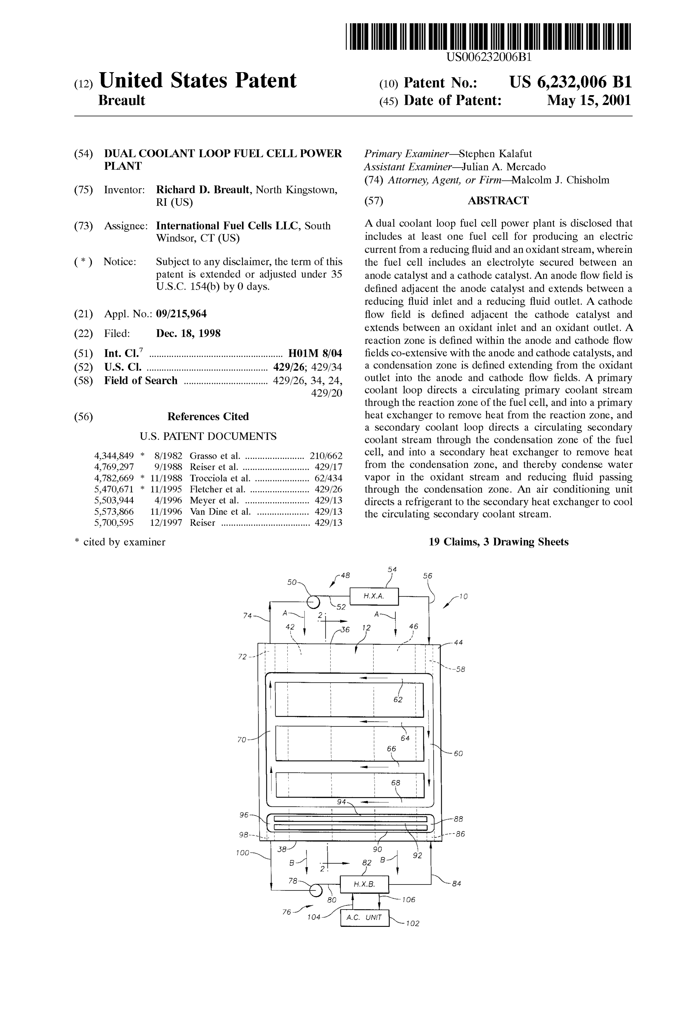
(12) United States Patent (10) Patent No.: US 6,232,006 B1 Breault (45) Date of Patent: May 15, 2001
(54) DUAL COOLANT LOOP FUEL CELL POWER Primary Examiner Stephen Kalafut PLANT ASSistant Examiner Julian A. Mercado (74) Attorney, Agent, or Firm Malcolm J. Chisholm (75) Inventor: Richard D. Breault, North Kingstown,
RI (US) (57) ABSTRACT (73) Assignee: International Fuel Cells LLC, South A dual coolant loop fuel cell power plant is disclosed that Windsor, CT (US) includes at least one fuel cell for producing an electric current from a reducing fluid and an oxidant Stream, wherein (*) Notice: Subject to any disclaimer, the term of this the fuel cell includes an electrolyte Secured between an patent is extended or adjusted under 35 anode catalyst and a cathode catalyst. An anode flow field is U.S.C. 154(b) by 0 days. defined adjacent the anode catalyst and extends between a reducing fluid inlet and a reducing fluid outlet. A cathode (21) Appl. No.: 09/215,964 flow field is defined adjacent the cathode catalyst and extends between an oxidant inlet and an oxidant outlet. A (22) Filed: Dec. 18, 1998 reaction Zone is defined within the anode and cathode flow (51) Int. Cl." .................................................. HO1M 8/04 fields co-extensive with the anode and cathode catalysts, and (52) U.S. Cl. ................................................. 429/26; 429/34 a condensation Zone is defined extending from the oxidant (58) Field of Search .................................. 429/26, 34, 24,
outlet into the anode and cathode flow fields. A primary coolant loop directs a circulating primary coolant Stream through the reaction Zone of the fuel cell, and into a primary (56) References Cited heat eXchanger to remove heat from the reaction Zone, and a Secondary coolant loop directs a circulating Secondary
4,344,849 8/1982 Grasso et al. ........................ 210662 cell, and into a secondary heat exchanger to remove heat 4,769,297 9/1988 Reiser et al. ...... ... 429/17 from the condensation Zone, and thereby condense water 4,782,669 * 11/1988 Trocciola et al. . . . 62/434 Vapor in the oxidant Stream and reducing fluid passing 5,470,671 * 11/1995 Fletcher et al. ... . . 429/26 through the condensation Zone. An air conditioning unit 5,503,944 4/1996 Meyer et al. ..... . . 429/13 directs a refrigerant to the Secondary heat eXchanger to cool 5,573,866 11/1996 Van Dine et al. 429/13 the circulating Secondary coolant Stream. 5,700,595 12/1997 Reiser .................................... 429/13 * cited by examiner 19 Claims, 3 Drawing Sheets
Page 2
Drawing sheet — no readable text.
Page 3
Drawing sheet — no readable text.
Page 4
iN Š glls S as S 5 SSS N NTT S is R 5 NNN
Sss N S5 3
SNNY T - O GSNNN U N C
...)NYNN
CD 1N ra N s S TNN
s S.O SC) S S SQ SQ S S S
Page 5
DUAL COOLANT LOOP FUEL CELL POWER Stack of Such fuel cells can be started rapidly providing PLANT operational flexibility for transportation and Stationery applications. As is well-known however, PEM cells have
TECHNICAL FIELD Significant limitations especially related to liquid water transport to, through and away from the PEM, and related to
The present invention relates to fuel cell power plants that Simultaneous transport of gaseous reducing and oxidant operate at about ambient preSSures and are Suited for usage fluids to and from the catalysts adjacent opposed Surfaces of in transportation vehicles, as portable power plants, or as the PEM. The prior art includes many efforts to minimize the Stationary power plants, and the invention especially relates effect of those limitations.
to a fuel cell power plant that utilizes coolant loops to 1O In operation of a fuel cell employing a PEM, the mem enhance water balance and energy efficiency of the plant. brane is Saturated with water, and the anode catalyst adjacent BACKGROUND OF THE INVENTION the membrane must remain wet. AS hydrogen ions produced at the anode catalyst transfer through the electrolyte, they
Fuel cell power plants are well-known and are commonly drag water molecules with them from the anode to the used to produce electrical energy from reducing and oxidiz 15 cathode. Water also transfers back to the anode from the ing fluids to power electrical apparatuS Such as apparatus cathode by osmosis. Product water formed at the cathode on-board Space vehicles. In Such power plants, a plurality of catalyst is removed by evaporation or entrainment into a planar fuel cells are typically arranged in a Stack Surrounded circulating gaseous Stream of oxidant, or by capillary action by an electrically insulating frame that defines manifolds for into and through a porous Support fluid transport layer directing flow of reducing, oxidizing, coolant and product adjacent the cathode. Porous water transport plates Supply fluids. Each individual cell generally includes an anode liquid water from a Supply of coolant water to the anode electrode or catalyst and a cathode electrode or catalyst catalyst and remove water from the cathode catalyst return Separated by an electrolyte. A reducing fluid Such as hydro ing it back to the coolant water Supply, and the plates thereby gen is Supplied to the anode catalyst, and an oxidant Such as also serve to remove heat from the electrolyte and catalysts, oxygen or air is Supplied to the cathode catalyst. In a cell 25 as described in U.S. Pat. Nos. 4,769,297 and 5,503.944 utilizing a proton eXchange membrane as the electrolyte, the assigned to the assignee of the present invention. hydrogen electrochemically reacts at a Surface of the anode During operation of PEM fuel cells, it is critical that a catalyst to produce hydrogen ions and electrons. The elec proper water balance be maintained between a rate at which trons are conducted to an external load circuit and then water is produced at the cathode catalyst and rates at which returned to the cathode catalyst, while the hydrogen ions water is removed from the cathode catalyst and at which transfer through the electrolyte to the cathode catalyst, liquid water is Supplied to the anode catalyst. An operational where they react with the oxidant and electrons to produce limit on performance of a fuel cell is defined by an ability of water and release thermal energy. It is common in fuel cell the cell to maintain the water balance as electrical current technology to refer to the locations of the aforesaid electro drawn from the cell into the external load circuit varies and chemical reactions as “electrodes', which often is meant to 35 as an operating environment of the cell varies. For PEM fuel include both a catalyst Such as platinum and a Support cells, if insufficient water is returned to the anode catalyst, Structure Such as a porous carbon Substrate. However, occa adjacent portions of the PEM electrolyte dry out thereby sionally the term “electrode” also includes portions of the decreasing the rate at which hydrogen ions may be trans Support Structure that does not include a catalyst, Such as an ferred through the PEM and also resulting in cross-over of edge portion. For purposes of clarity herein, the term “cata 40 the reducing fluid leading to local over heating. Similarly, if lyst” will be used, as “anode catalyst” and “cathode insufficient water is removed from the cathode, the cathode catalyst”, instead of “electrode' to identify only the location catalyst may become flooded effectively limiting oxidant of catalysts that catalyze electrochemical reactions within a Supply to the cathode and hence decreasing current flow. fuel cell. Additionally, if too much water is removed from the cathode The anode and cathode catalysts of Such fuel cells are 45 by the gaseous Stream of oxidant, the cathode may dry out Separated by different types of electrolytes depending on limiting ability of hydrogen ions to pass through the PEM, operating requirements and limitations of the working envi thus decreasing cell performance.
ronment of the fuel cell. One Such electrolyte is a proton AS fuel cells have been integrated into power plants exchange membrane (“PEM”) electrolyte, which consists of developed to power transportation vehicles Such as a solid polymer well-known in the art. Other common 50 automobiles, trucks, buses, etc., maintaining an efficient electrolytes used in fuel cells include phosphoric acid or water balance within the power plant has become a greater potassium hydroxide held within a porous, nonconductive challenge because of a variety of factors. For example, with matrix between the anode and cathode catalysts. a Stationary fuel cell power plant, water lost from the plant It has been found that PEM cells have Substantial advan may be replaced by water Supplied to the plant from off tages over cells with liquid acid or alkaline electrolytes in 55 plant Sources. With a transportation vehicle, however, to Satisfying Specific operating parameters because the mem minimize weight and Space requirements of a fuel cell power brane of the PEM provides a barrier between the reducing plant the plant must be self-sufficient in water to be viable. fluid and oxidant that is more tolerant to pressure differen Self-Sufficiency in water means that enough water must be tials than a liquid electrolyte held by capillary forces within retained within the plant to offset losses from reactant fluids a porous matrix. Additionally, the PEM electrolyte is fixed, 60 exiting the plant in order to efficiently operate the plant. Any and cannot be leached from the cell, and the membrane has water exiting the plant through a plant exhaust Stream a relatively stable capacity for water retention. Furthermore, consisting of a cathode exhaust Stream of gaseous oxidant because Specific electrode or catalyst reactions proceed and/or an anode exhaust Stream of gaseous reducing fluid rapidly in a PEM fuel cell, high power densities can be must be balanced by water produced electrochemically at obtained at low catalyst loadings leading to a low cost power 65 the cathode catalyst and water retained within the plant. plant with high power densities. Finally, because a PEM fuel For example, an ambient pressure, gasoline powered PEM cell operates at low temperatures, a power plant including a fuel cell must be self-sufficient in water to be a viable power
Page 6
Source for vehicles. Such a power Source requires fuel anode Side of the cell wherein gaseous reducing fluids are processing components to process the gasoline into a hydro maintained at a slightly higher pressure than coolant water gen rich reactant fluid. The fuel processing components use and anode Supply water passing through the porous Support water heated to Steam in a boiler to aid in processing the layers adjacent reducing gas distribution channels So that the gasoline, and the water for the fuel processing components preSSure differential assists water transport through the must be Supplied from water produced at the cathode in the porous Support layers and cell; and, increasing air utilization fuel cell as a result of the above described electrochemical by the cathode through decreasing Volumetric flow of the reaction. AS is well-known however, the water produced at oxidant Stream by the cathode. Such efforts at maintaining the cathode catalyst is swept from the cell within the cathode efficient water balance involve additional cost, weight, Vol exhaust Stream. It is known to recover Some of the water in ume burdens, fuel cell performance penalties, and often the cathode exhaust Stream by passing the cathode exhaust require complicated control apparatus. Stream through a condensing heat eXchanger to cool the
Stream and thereby condense the water out of the Stream. fuelAncell alternative approach to enhancing water balance for power plants in transportation vehicles is to pres
The condensed water is then accumulated and directed to the fuel processing components as required to maintain the plant 15 Surize the cell and related components. This increaseS reac in water balance. tant concentrations in high pressure gaseous Streams and An example of a PEM fuel cell power plant using a reducing also reduces water loSS through plant exhaust Streams by condensing heat exchanger is shown in U.S. Pat. No. 5,573, fuel cell Volumetric power flow of the Streams. Such pressurized plants, however, require additional cost, 866 that issued on Nov. 12, 1996 to Van Dine et al., and is weight and control apparatus in providing appropriate pres assigned to the assignee of the present invention, and which Sure housings and controls, and patent is hereby incorporated herein by reference. Many additional energy derived from thepressurized plants require other fuel cell power plants that use one or more condensing izing pumps, valves, fans, etc., and are not knownpreSSur plant to operate
heat eXchangers are well-known in the art, and they typically practical for portable power plants. use ambient air Streams as a cooling fluid passing through the exchanger to cool the plant exhaust Streams. In Van Dine 25 Accordingly, known preSSurized plants and plants that et al., the heat eXchanger is used to cool an exhaust Stream employ ambient air as the cathode oxidant or that use exiting a cathode chamber housing the cathode catalyst. ambient air for condensing heat eXchangers are incapable of Prior to entering the cathode housing, the same Stream maximizing an efficient water balance and minimizing oper provides air as the oxidant for the cathode catalyst, and upon ating energy requirements because of their above described leaving the chamber the Stream includes evaporated product characteristics. It is therefore highly desirable to produce a water and Some portion of methanol, the reducing fluid, that fuel cell power plant that minimizes reliance upon ambient has passed through the PEM. The condensing heat in air cooled condensing heat eXchangers to maintain the plant eXchanger passes the cathode exhaust Stream in heat water balance.
eXchange relationship with a stream of cooling ambient air, DISCLOSURE OF THE INVENTION and then directs condensed methanol and water indirectly 35 through a piping System back to an anode Side of the cell. The invention is a dual coolant loop fuel cell power plant While condensing heat eXchangers have enhanced water that includes at least one fuel cell for producing an electric balance and energy efficiency of ambient fuel cell power current from a reducing fluid and an oxidant Stream. The fuel plants, the heat eXchangers encounter decreasing water cell includes an electrolyte Secured between an anode cata recovery efficiency as ambient temperatures increase. Where 40 lyst and a cathode catalyst, an anode flow field defined the power plant is to power a transportation vehicle Such as adjacent the anode catalyst and extending between a reduc an automobile, the plant will be exposed to an extremely ing fluid inlet and a reducing fluid outlet, a cathode flow field wide range of ambient temperatures. For example where an defined adjacent the cathode catalyst and extending between ambient air cooling fluid passes through a heat eXchanger, an oxidant inlet and an oxidant outlet, a reaction Zone performance of the eXchanger will vary as a direct function 45 defined within the anode and cathode flow fields of the temperature of the ambient air because decreasing co-extensive with the anode and cathode catalysts, and a amounts of liquid precipitate out of power plant exhaust condensation Zone defined as extending from the oxidant Streams as the ambient air temperature increases. outlet into the anode and cathode flow fields. A primary An additional complication of known fuel cell power coolant loop directs a primary coolant Stream through pri plants designed for use in transportation vehicles is also 50 mary coolant passages within the reaction Zone of the fuel related to fluctuations in ambient air conditions. Fuel cells of cell, out of the fuel cell into a primary heat eXchanger to Such plants typically utilize ambient air as the oxidant remove heat from the reaction Zone, and back into the directed to the cathode catalyst. Hot and dry ambient air primary coolant passages as a circulating primary coolant increases a risk that the cathode catalyst will dry out because Stream. A Secondary coolant loop directs a Secondary cool Such hot, dry air removes water more quickly by evaporation 55 ant Stream through Secondary coolant passages within the than does cool, moist oxidant Supply air. Such hot, dry condensation Zone of the fuel cell, out of the fuel cell into ambient air raises a dewpoint of the plant exhaust Stream a Secondary heat eXchanger and back into the fuel cell as a effectively moving the plant out of water balance. circulating Secondary coolant Stream. An air conditioning Consequently, many efforts have been undertaken to unit directs a refrigerant to the Secondary heat eXchanger to prevent excess water loSS resulting in drying out of the 60 cool the circulating Secondary coolant Stream. cathode catalyst and adjacent electrolyte especially in PEM The dual coolant loop fuel cell power plant may be used, fuel cells, including: directing liquid condensate from con for example, in a vehicle Such as an automobile to power an densing heat eXchangers to humidify gaseous reactant and electric motor to operate the vehicle wherein the oxidant oxidant Streams entering the cell; adding porous Support Supplied to the cathode catalyst is ambient air. AS ambient layerS and water transport plates in fluid communication 65 temperatures climb based on a change in an operating with the catalysts for movement of coolant water through environment of the vehicle, the oxidant Supplied to the adjacent cells, generating a pressure differential on the cathode catalyst increases in temperature and is therefore
Page 7
S 6 able to hold as water vapor an increased amount of water brane (“PEM”) or an acid or base electrolyte; an anode generated at the cathode catalyst as the oxidant Stream catalyst 16, Supported by an anode Support layer 18 in moves through the reaction Zone. Consequently, that intimate contact with the anode catalyst 16, an anode water increased amount of water vapor within both the oxidant transport plate 20 in contact with the anode support layer 18; Stream and a reducing fluid Stream within the fuel cell is at and, a cathode catalyst 22, Supported by a cathode Support risk of being swept out of the fuel cell with the oxidant as layer 24 in intimate contact with the cathode catalyst 22, and a cathode exhaust Stream and with the reducing fluid as an a cathode water transport plate 26 in contact with the anode exhaust Stream, and the fuel cell is in jeopardy of cathode Support layer 24.
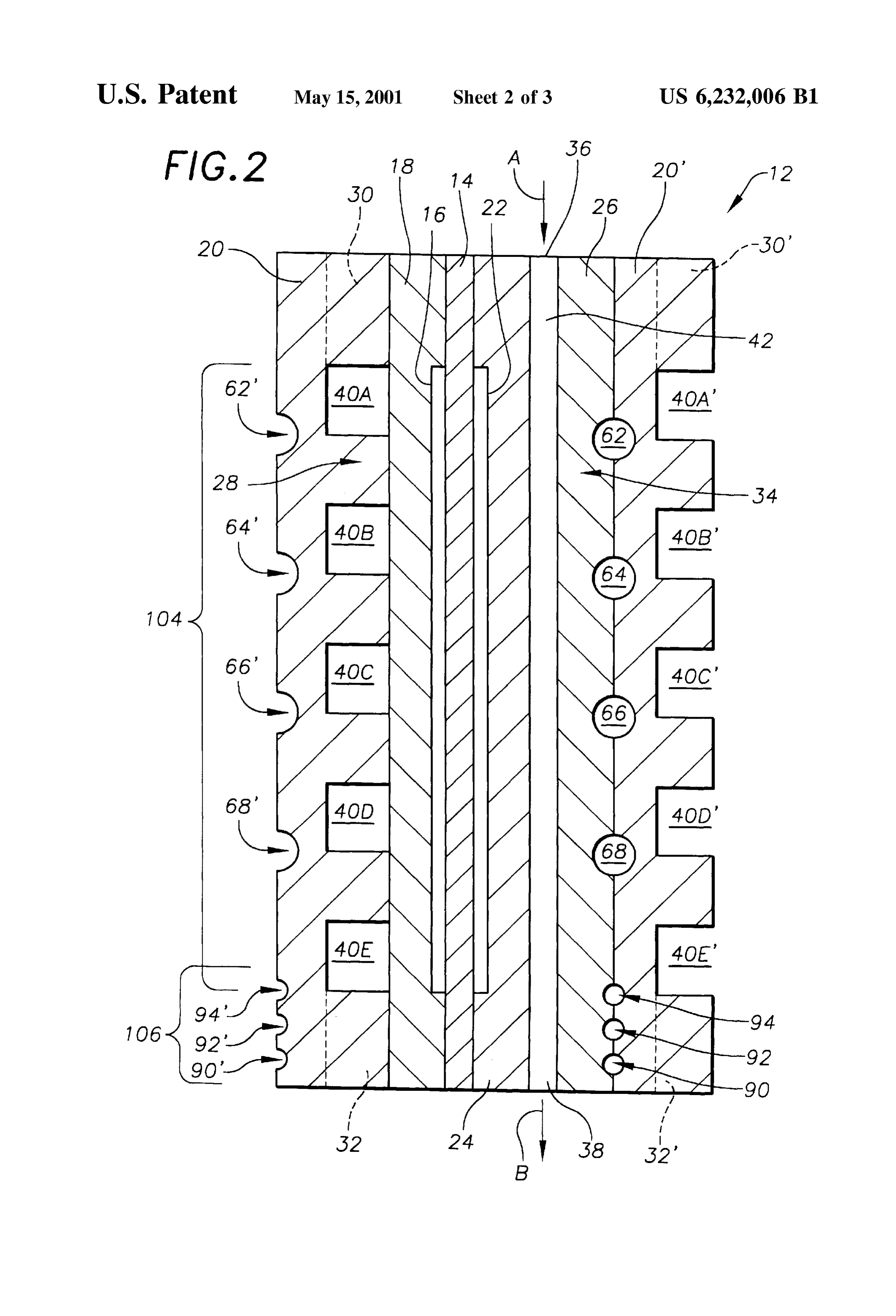
moving out of water balance. The air conditioning unit is The anode water transport plate 20 may be formed of then activated to Supply refrigerant to the Secondary heat porous or non-porous graphite, carbon or metal layerS So that eXchanger to lower the temperature of the circulating Sec pores, channels or Voids in the anode water transport plate ondary coolant Stream which lowers the temperature of the 20 cooperate to define an anode flow field 28 adjacent the oxidant Stream and the reducing fluid passing through the anode catalyst 16 and extending between a reducing fluid condensation Zone resulting in condensation of water vapor inlet 30 and a reducing fluid outlet 32 for directing the within the Oxidant and reducing fluid Streams before they 15 reducing fluid to pass by the anode catalyst 16. Similarly, leave the fuel cell. The condensation Zone preferably cathode water transport plate 26 may also be formed of includes porous layers to collect the condensed water and porous or non-porous graphite, carbon or metal layerS So that retain the condensed water within the fuel cell. Alternatively, pores, Voids or channels in the cathode water transport plate the anode and cathode flow fields within the condensation 26 cooperate to define a cathode flow field 34 adjacent the Zone may be Solid defining voids and passageways wherein cathode catalyst 22 and extending between an oxidant inlet liquid condensate is removed by entrainment in the cathode 36 and an oxidant outlet 38 for directing the oxidant stream and anode exhaust Streams and collected in a liquid-air to pass by the cathode catalyst 22. AS shown for example in Separator. By utilizing the Secondary coolant loop having a FIG. 2, the anode water transport plate 20 defines a plurality refrigerant cooled heat eXchanger, the power plant may be of reducing fluid feed channels 40A, 40B, 40C, 40D, 40E, maintained in water balance without having to pass the fuel 25 that are in fluid communication with the reducing fluid inlet cell exhaust Streams through an ambient air cooled condens 30 and outlet 32 to facilitate distribution of a reducing fluid ing heat eXchanger downstream of the fuel cell. within the anode flow field 28, and pores of the anode water Accordingly, it is a general object of the present invention transport plate and adjacent anode Support layer 18 further to provide a dual coolant loop fuel cell power plant that facilitate distribution of the reducing fluid to the anode catalyst 16. The cathode water transport plate 26 similarly overcomes deficiencies of the prior art.
It is a more Specific object to provide a dual coolant loop defines inlet 36 an oxidant passage 42 extending between oxidant and oxidant outlet 38, and pores of the cathode fuel cell power plant that utilizes a conventional air condi support layer 24 facilitate distribution of the oxidant to the tioning unit of a passenger vehicle Such as an automobile to cathode catalyst 22.
enhance water retention of a fuel cell power plant. 35 It is noted that a Second anode water transport plate 20' is It is a further Specific object to provide a dual coolant loop shown in FIG. 2 adjacent the cathode water transport plate fuel cell power plant that includes components for retaining 26 to facilitate understanding of Stacking of fuel cells water within the plant that may be utilized while minimizing together to form a cell stack assembly (“CSA") well-known performance penalties of the cell. in the art. Elements of that Second anode water transport These and other objects and advantages of this invention 40 plate 20' are the same as elements of the anode water will become more readily apparent when the following transport plate 20, and are designated by primes of the same description is read in conjunction with the accompanying reference numerals as for the plate 20, such as 30', etc. It is drawings. also stressed that, while the FIG. 2 juxtaposition of the oxidant passage 42 and reducing fluid feed channels
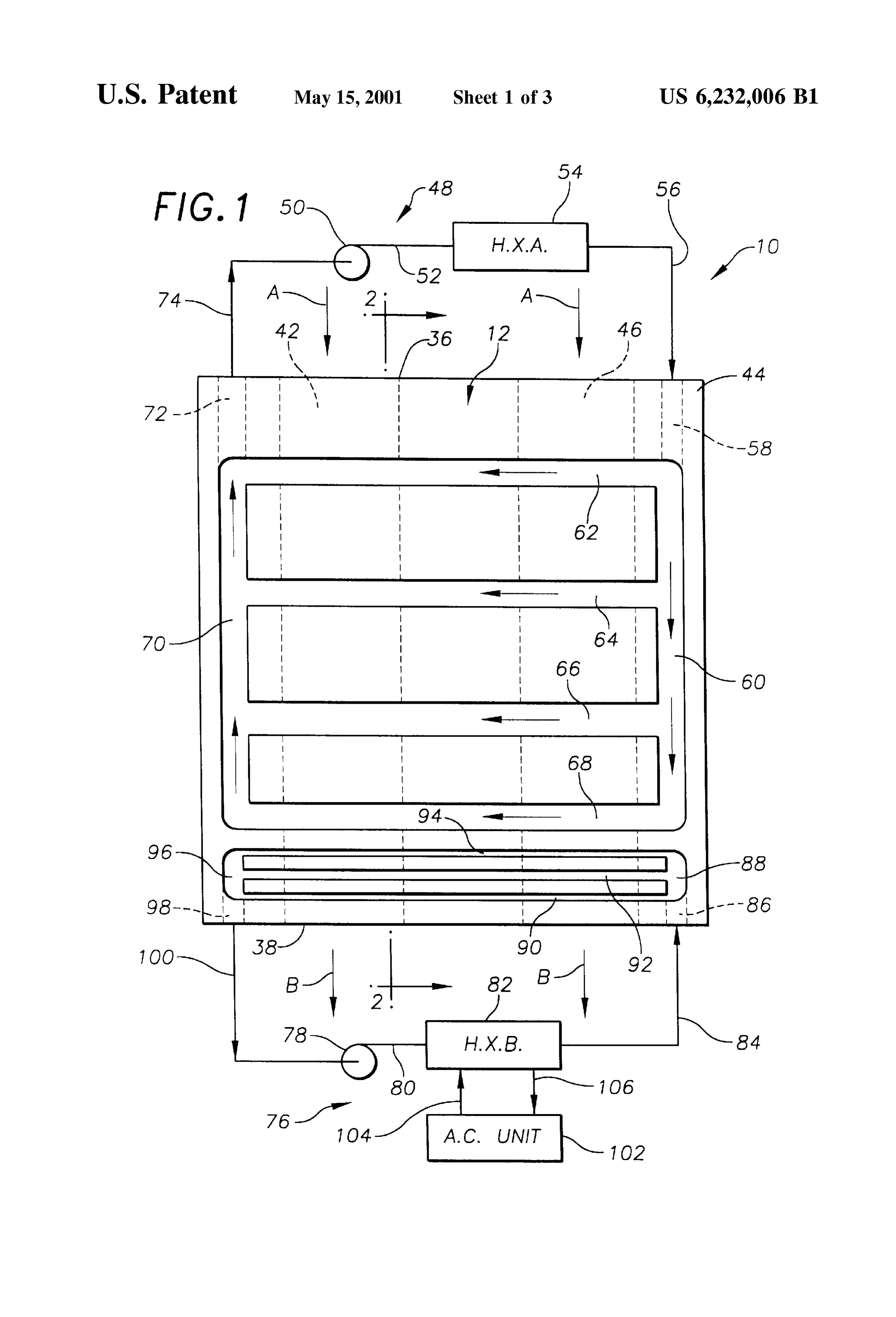
BRIEF DESCRIPTION OF THE DRAWINGS 45 40A-40E appears to provide for movement of the reducing FIG. 1 is a Schematic, cross-section view of a dual coolant fluid and oxidant in a crossing flow pattern (e.g., along axes at ninety degrees to each other), the present invention is not loop fuel cell power plant constructed in accordance with the limited present invention. to Such a relationship, and opposed flow, parallel flow, or any
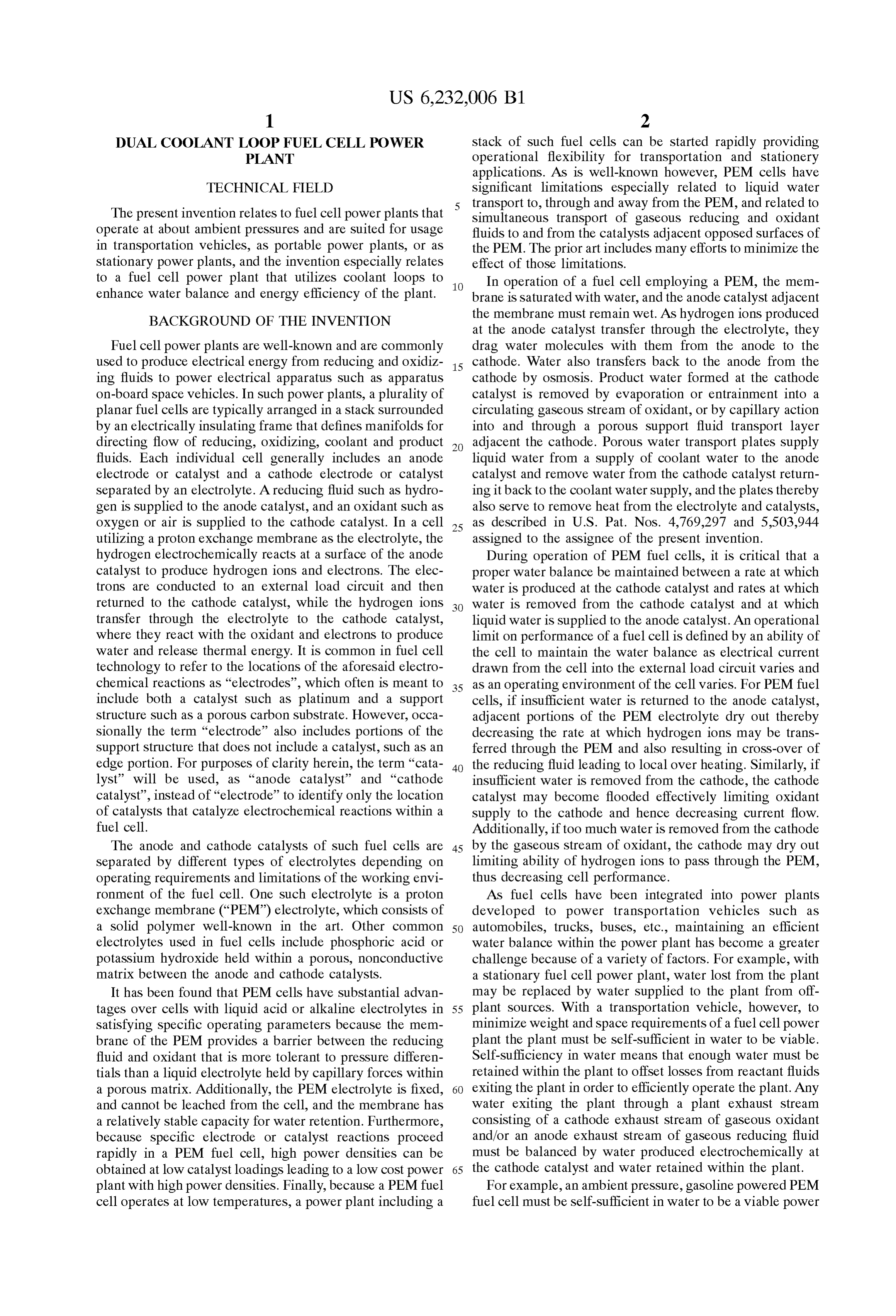
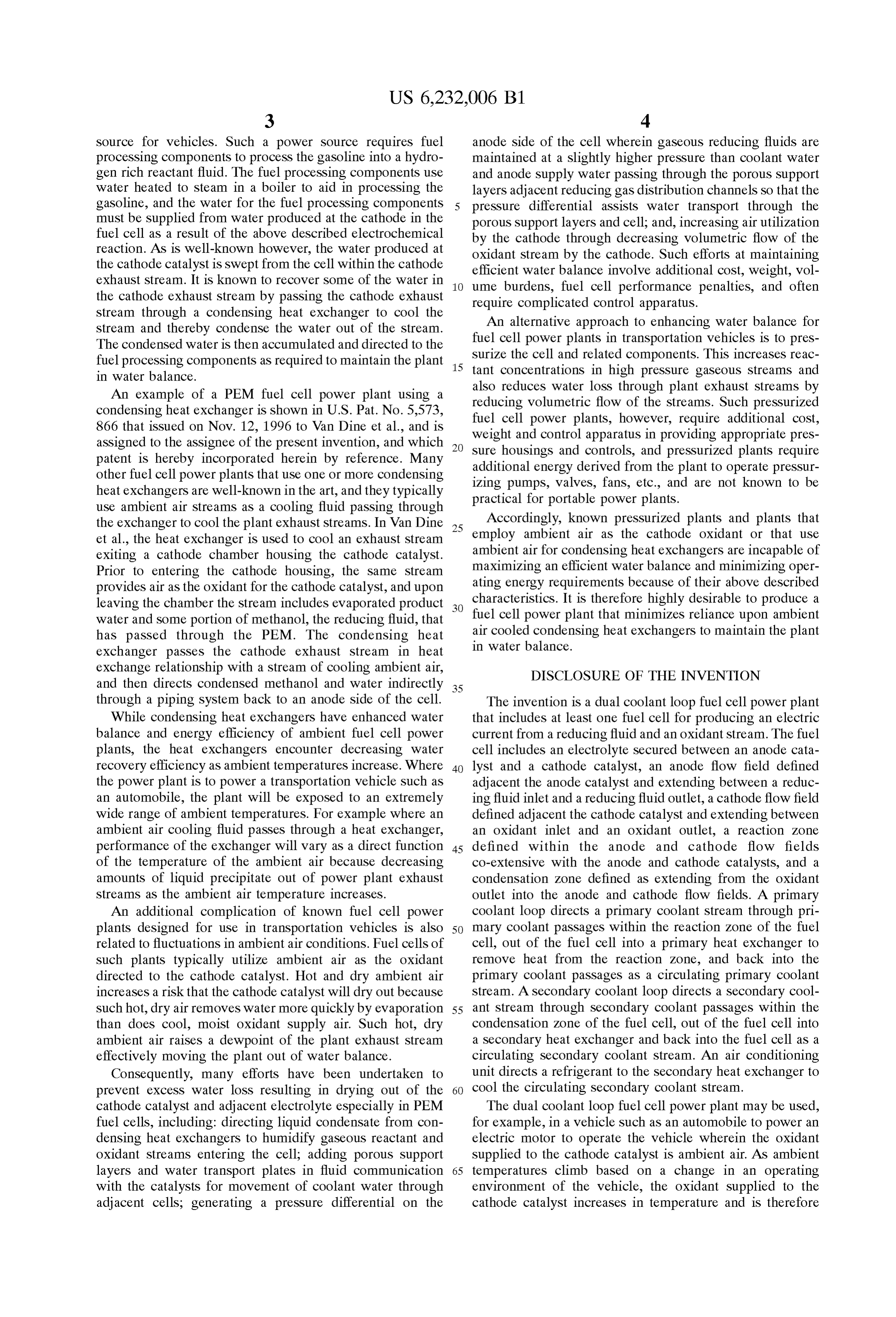
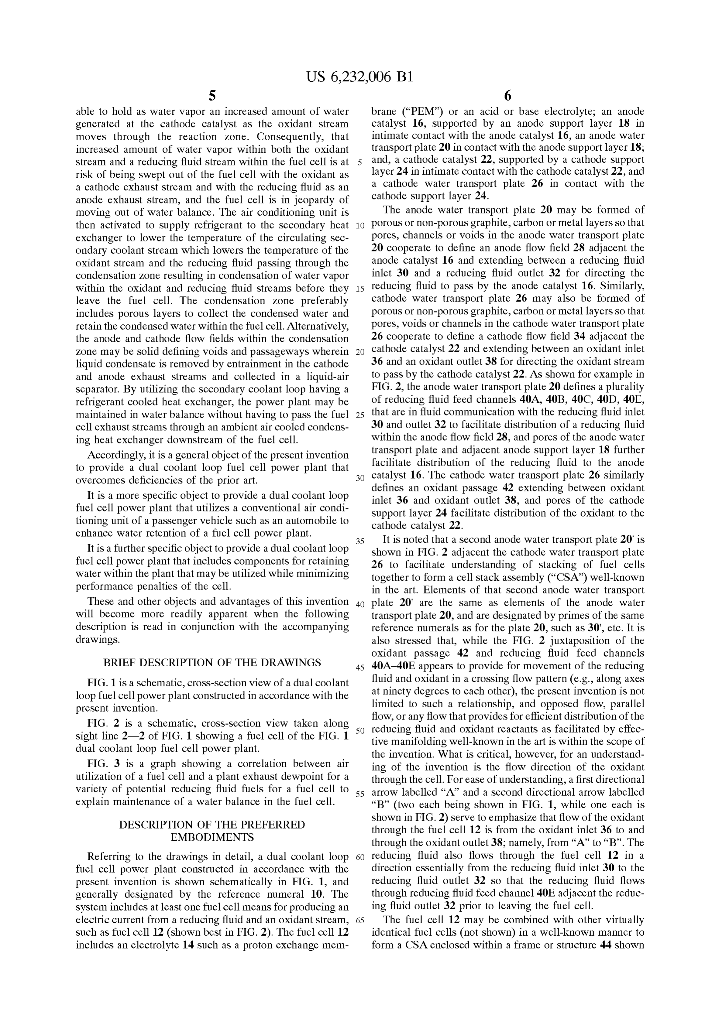
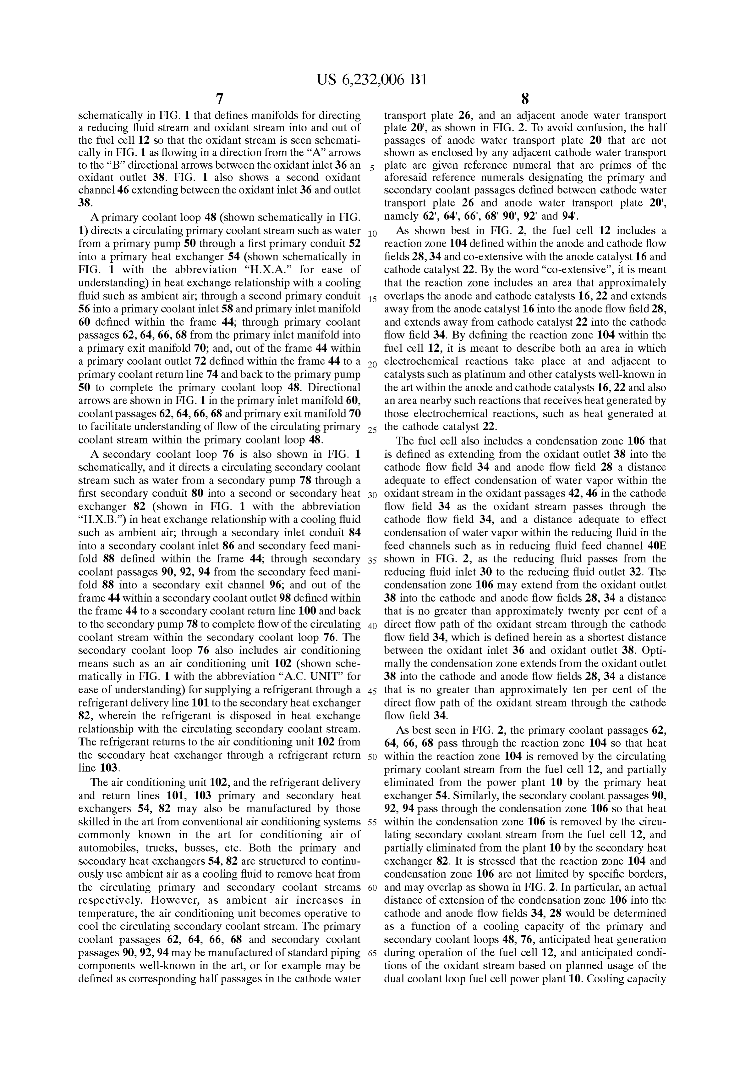
FIG. 2 is a Schematic, croSS-Section view taken along 50 reducing fluid flow that provides for efficient distribution of the sight line 2-2 of FIG. 1 showing a fuel cell of the FIG. 1 tive manifoldingandwell-known oxidant reactants as facilitated by effec in the art is within the scope of dual coolant loop fuel cell power plant. the invention. What is critical, however, for an understand FIG. 3 is a graph showing a correlation between air ing of the invention is the flow direction of the oxidant utilization of a fuel cell and a plant exhaust dewpoint for a through the cell. For ease of understanding, a first directional variety of potential reducing fluid fuels for a fuel cell to 55 arrow labelled “A” and a second directional arrow labelled explain maintenance of a water balance in the fuel cell. “B” (two each being shown in FIG. 1, while one each is DESCRIPTION OF THE PREFERRED shown in FIG. 2) serve to emphasize that flow of the oxidant EMBODIMENTS through the fuel cell 12 is from the oxidant inlet 36 to and through the oxidant outlet 38; namely, from “A” to “B”. The
Referring to the drawings in detail, a dual coolant loop 60 reducing fluid also flows through the fuel cell 12 in a fuel cell power plant constructed in accordance with the direction essentially from the reducing fluid inlet 30 to the present invention is shown Schematically in FIG. 1, and reducing fluid outlet 32 so that the reducing fluid flows generally designated by the reference numeral 10. The through reducing fluid feed channel 40E adjacent the reduc System includes at least one fuel cell means for producing an ing fluid outlet 32 prior to leaving the fuel cell. electric current from a reducing fluid and an oxidant Stream, 65 The fuel cell 12 may be combined with other virtually such as fuel cell 12 (shown best in FIG. 2). The fuel cell 12 identical fuel cells (not shown) in a well-known manner to includes an electrolyte 14 Such as a proton exchange mem form a CSA enclosed within a frame or structure 44 shown
Page 8
schematically in FIG. 1 that defines manifolds for directing transport plate 26, and an adjacent anode water transport a reducing fluid Stream and oxidant Stream into and out of plate 20', as shown in FIG. 2. To avoid confusion, the half the fuel cell 12 So that the oxidant Stream is seen Schemati passages of anode water transport plate 20 that are not cally in FIG. 1 as flowing in a direction from the “A” arrows shown as enclosed by any adjacent cathode water transport to the “B” directional arrows between the oxidant inlet 36 an plate are given reference numeral that are primes of the oxidant outlet 38. FIG. 1 also shows a second oxidant aforesaid reference numerals designating the primary and channel 46 extending between the oxidant inlet 36 and outlet Secondary coolant passages defined between cathode water 38. transport plate 26 and anode water transport plate 20', A primary coolant loop 48 (shown schematically in FIG. namely 62', 64", 66', 68'90", 92 and 94'. 1) directs a circulating primary coolant stream Such as water As shown best in FIG. 2, the fuel cell 12 includes a from a primary pump 50 through a first primary conduit 52 reaction Zone 104 defined within the anode and cathode flow into a primary heat exchanger 54 (shown Schematically in fields 28,34 and co-extensive with the anode catalyst 16 and FIG. 1 with the abbreviation “H.X.A. for ease of cathode catalyst 22. By the word “co-extensive”, it is meant understanding) in heat exchange relationship with a cooling that the reaction Zone includes an area that approximately fluid Such as ambient air, through a Second primary conduit 15 overlaps the anode and cathode catalysts 16, 22 and extends 56 into a primary coolant inlet 58 and primary inlet manifold away from the anode catalyst 16 into the anode flow field 28, 60 defined within the frame 44; through primary coolant and extends away from cathode catalyst 22 into the cathode passages 62, 64, 66, 68 from the primary inlet manifold into flow field 34. By defining the reaction Zone 104 within the a primary exit manifold 70; and, out of the frame 44 within fuel cell 12, it is meant to describe both an area in which a primary coolant outlet 72 defined within the frame 44 to a electrochemical reactions take place at and adjacent to primary coolant return line 74 and back to the primary pump catalysts Such as platinum and other catalysts well-known in 50 to complete the primary coolant loop 48. Directional the art within the anode and cathode catalysts 16, 22 and also arrows are shown in FIG. 1 in the primary inlet manifold 60, an area nearby Such reactions that receives heat generated by coolant passages 62, 64, 66, 68 and primary exit manifold 70 those electrochemical reactions, Such as heat generated at to facilitate understanding of flow of the circulating primary 25 the cathode catalyst 22.
coolant Stream within the primary coolant loop 48. The fuel cell also includes a condensation Zone 106 that A secondary coolant loop 76 is also shown in FIG. 1 is defined as extending from the oxidant outlet 38 into the Schematically, and it directs a circulating Secondary coolant cathode flow field 34 and anode flow field 28 a distance Stream Such as water from a Secondary pump 78 through a adequate to effect condensation of water vapor within the first secondary conduit 80 into a second or secondary heat oxidant Stream in the oxidant passages 42, 46 in the cathode exchanger 82 (shown in FIG. 1 with the abbreviation flow field 34 as the oxidant stream passes through the “H.X.B.”) in heat exchange relationship with a cooling fluid cathode flow field 34, and a distance adequate to effect Such as ambient air; through a secondary inlet conduit 84 condensation of water vapor within the reducing fluid in the into a Secondary coolant inlet 86 and Secondary feed mani feed channels such as in reducing fluid feed channel 40E fold 88 defined within the frame 44; through secondary 35 shown in FIG. 2, as the reducing fluid passes from the coolant passages 90, 92, 94 from the secondary feed mani reducing fluid inlet 30 to the reducing fluid outlet 32. The fold 88 into a secondary exit channel 96; and out of the condensation Zone 106 may extend from the oxidant outlet frame 44 within a secondary coolant outlet 98 defined within 38 into the cathode and anode flow fields 28, 34 a distance the frame 44 to a secondary coolant return line 100 and back that is no greater than approximately twenty per cent of a to the secondary pump 78 to complete flow of the circulating 40 direct flow path of the oxidant stream through the cathode coolant stream within the secondary coolant loop 76. The flow field 34, which is defined herein as a shortest distance Secondary coolant loop 76 also includes air conditioning between the oxidant inlet 36 and oxidant outlet 38. Opti means Such as an air conditioning unit 102 (shown Sche mally the condensation Zone extends from the oxidant outlet matically in FIG. 1 with the abbreviation “A.C. UNIT" for 38 into the cathode and anode flow fields 28, 34 a distance ease of understanding) for Supplying a refrigerant through a 45 that is no greater than approximately ten per cent of the refrigerant delivery line 101 to the Secondary heat eXchanger direct flow path of the oxidant stream through the cathode 82, wherein the refrigerant is disposed in heat eXchange flow field 34.
relationship with the circulating Secondary coolant Stream. AS best Seen in FIG. 2, the primary coolant passages 62, The refrigerant returns to the air conditioning unit 102 from 64, 66, 68 pass through the reaction Zone 104 So that heat the Secondary heat eXchanger through a refrigerant return 50 within the reaction Zone 104 is removed by the circulating line 103. primary coolant Stream from the fuel cell 12, and partially The air conditioning unit 102, and the refrigerant delivery eliminated from the power plant 10 by the primary heat and return lines 101, 103 primary and secondary heat eXchanger 54. Similarly, the Secondary coolant passages 90, exchangers 54, 82 may also be manufactured by those 92, 94 pass through the condensation Zone 106 so that heat skilled in the art from conventional air conditioning Systems 55 within the condensation Zone 106 is removed by the circu commonly known in the art for conditioning air of lating Secondary coolant Stream from the fuel cell 12, and automobiles, trucks, buSSes, etc. Both the primary and partially eliminated from the plant 10 by the secondary heat Secondary heat eXchangers 54, 82 are Structured to continu exchanger 82. It is stressed that the reaction Zone 104 and ously use ambient air as a cooling fluid to remove heat from condensation Zone 106 are not limited by specific borders, the circulating primary and Secondary coolant Streams 60 and may overlap as shown in FIG. 2. In particular, an actual respectively. However, as ambient air increases in distance of extension of the condensation Zone 106 into the temperature, the air conditioning unit becomes operative to cathode and anode flow fields 34, 28 would be determined cool the circulating Secondary coolant Stream. The primary as a function of a cooling capacity of the primary and coolant passages 62, 64, 66, 68 and Secondary coolant Secondary coolant loopS 48, 76, anticipated heat generation passages 90,92, 94 may be manufactured of standard piping 65 during operation of the fuel cell 12, and anticipated condi components well-known in the art, or for example may be tions of the oxidant Stream based on planned usage of the defined as corresponding half passages in the cathode water dual coolant loop fuel cell power plant 10. Cooling capacity
Page 9
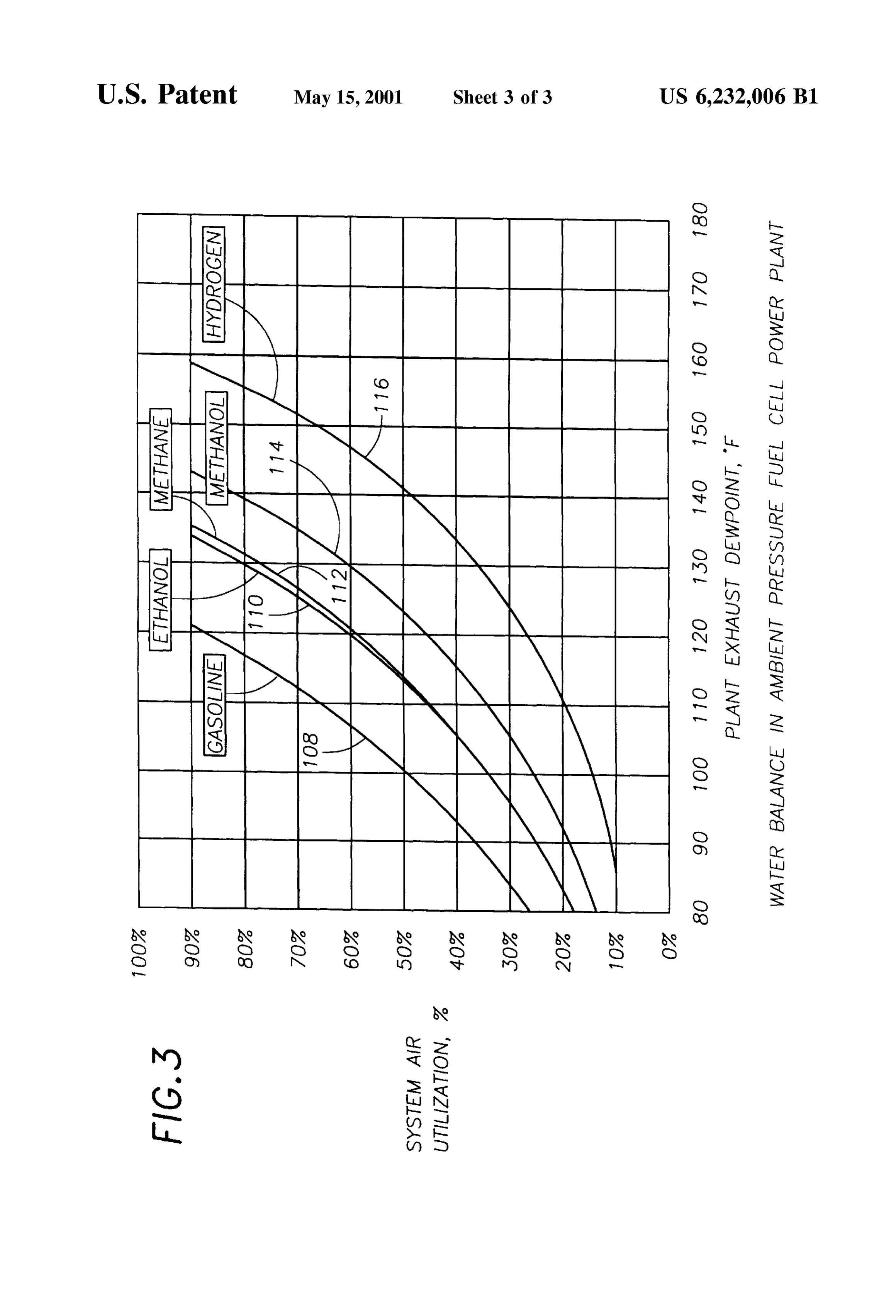
of the Secondary coolant loop 76 including placement and Utilization, %' means the ratio of air taken from the oxidant numbers of Secondary coolant passages Such as passages 90, stream and utilized by the dual loop fuel cell power plant 10 92, 94 would be designed to achieve water self-sufficiency in generating an electric current to the quantity of oxidant of the plant 10 under anticipated operating conditions So that supplied to the power plant 10. The graph shows that water water generated at the cathode catalyst and retained within Self-sufficiency or water balance is maintained at increas the plant 10 exceeds water used and/or lost by the plant 10. ingly higher plant exhaust dewpoints as the air utilization By utilizing the air conditioning unit 102 to cool the sec increases. Raising the air utilization reduces the vapor ondary heat eXchanger 82, the Secondary coolant loop 76 is preSSure difference between the oxidant Stream entering the able to cool the Oxidant Stream passing through the conden oxidant passage at the oxidant inlet 36 and the plant exhaust sation Zone 106 to a sufficiently low temperature to produce stream leaving the cell at the oxidant outlet 38, so that less condensation of water vapor within the oxidant Stream, water evaporates into the cathode exhaust Stream to leave thereby effectively reducing a dewpoint of the oxidant the cell. Therefore, by raising System air utilization, water Stream exiting the oxidant outlet 38 to become plant exhaust. balance is achieved at increasingly higher plant exhaust As shown in FIG. 2, the condensation Zone 106 includes dewpoints which enables the fuel cell 12 to operate at water portions of the cathode Support layer 24, cathode water 15 Self-sufficiency or in water balance at higher ambient tem transport plate 26, anode water transport plate, 20, 20', and peratures.
anode Support layer 18, all of which may be porous layers FIG. 3 plots a water-balance relationship between air that Support flow of both liquid and gaseous coolant, reactant utilization and dewpoint for five common fuels, wherein and product fluids through the fuel cell 12. Therefore, water gasoline is represented by line 108, ethanol by line 110, Vapor condensed out of the oxidant Stream passing through methane by line 112, methanol by line 114, and hydrogen by the condensation Zone 102 may readily pass into the cathode line 116. If a plot of the system air utilization and plant Support layer 24 or cathode water transport plate 26 to move exhaust dewpoint for one of the fuels at any given time throughout the cell as a coolant, or to move into the primary remains above the line for that fuel 108,110, 112,114 or 116, or secondary coolant passages 62, 64, 66, 68,90, 92, 94 to then the fuel cell power plant is in water balance, So that the become part of the circulating primary or Secondary coolant 25 amount of water being lost through the plant exhaust Stream StreamS. is less than the amount of water required for water Self The dual coolant loop fuel cell power plant 10 may be for Sufficiency. For example, if the fuel is gasoline, the System example an ambient preSSure, gasoline fueled power plant air utilization is 40% and the plant exhaust dewpoint is 90 utilized to power a transportation vehicle Such as an F., the power plant 10 is in water balance. However, if the automobile, truck, bus, etc., wherein the gasoline is system air utilization Suddenly shifts to 30%, a plant oper reformed into a hydrogen rich reducing fluid through fuel ating point is then below the water-balance line 108, and the processing means well-known in the art. Design estimates of plant 10 is out of water balance and in jeopardy of having such a use of the power plant 10 of the present invention inadequate water to operate the plant 10. have established that the primary coolant loop 48 would One method of returning the System back to water balance operate optimally by utilizing a primary heat eXchanger 54 35 is to increase the per cent air utilization through use of an Such as a Standard automobile radiator and primary coolant oxidant blower (not shown) upstream of the oxidant inlet 36 passages that are dimensioned to have a capacity to deliver to decrease Volumetric flow of the oxidant Stream passing the circulating primary coolant Stream to the primary coolant into the cathode flow field 34 through the Oxidant passage inlet 58 at a temperature of approximately 150 degrees 42, and thereby increase per cent air utilization and decrease fahrenheit (hereafter “F”) and remove the circulating pri 40 water loSS. However use of Such an oxidant blower can only mary coolant Stream from the primary coolant outlet 72 at a effect air utilization within a limited range and is not an temperature of approximately 170 F. Additionally, the adequate Solution for an ambient pressure fuel cell power Secondary coolant loop will perform optimally by utilizing plant. A better approach to returning the plant to water a Secondary heat eXchanger 82 and air conditioning unit 102, balance is through use of the air conditioning unit 102 of the Such as a Standard automobile air conditioning unit, and 45 Secondary coolant loop 76 to reduce the plant exhaust Secondary coolant passages that are dimensioned to have a dewpoint by reducing the temperature of the oxidant passing capacity to deliver the circulating Secondary coolant Stream through the oxidant Stream passage 42 and cathode flow to the Secondary inlet 86 at a temperature of approximately field 34 and of the reducing fluid Stream passing through the 90 F., and remove the circulating Secondary coolant Stream reducing fluid feed channel 40E and the anode flow field 28 from the secondary outlet 98 at a temperature of approxi 50 within the condensation Zone 106. By using the secondary mately 110 F. as the plant 10 is operated throughout a coolant loop 76 in such a manner, the plant 10 may be normal anticipated range of temperatures of ambient air that maintained in water balance without need of a condensing serves as both the oxidant for the fuel cell 12 and also as the heat eXchanger downstream of the Oxidant outlet 38 as is cooling fluid for the primary and Secondary heat eXchangers common in the art, and the primary heat eXchanger 54 may for known transportation vehicles. 55 be of a smaller structure than would be possible if the The above described operating ranges of temperatures of Secondary coolant loop 76 did not have the conditioning unit the circulating primary and Secondary coolant Streams are 102.
consistent with anticipated rates of air utilization by the fuel Under most operating conditions, a method of operating cell of between thirty five to forty eight per cent. FIG.3 aids the dual coolant loop power plant 10 includes the steps of in explaining how the dual loop fuel cell power plant 10 of 60 directing the circulating primary coolant Stream through the the present invention helps achieve water Self-sufficiency by reaction Zone 104 and through the first ambient cooled heat plotting data on a graph related to both per cent air utiliza eXchanger 54 to remove heat from the reaction Zone, and tion and plant exhaust dewpoints. The FIG. 3 graph is directing the circulating Secondary coolant Stream through entitled “Water Balance in Ambient Pressure Fuel Cell the condensation Zone and through the ambient cooled Power Plant”, and shows a relationship between “Plant 65 Secondary heat eXchanger 82 to remove heat from the Exhaust Dewpoint” on an X axis and “System Air condensation Zone. However, upon transition of the plant out Utilization, %' on a Y axis. The phrase “System Air of water balance or water Self-sufficiency by a Sudden
Page 10
decrease in a rate of air utilization or by an increase in plant liquid coolant Stream to the reaction Zone at a temperature of exhaust dewpoints as a result of higher ambient approximately 150 F., and remove the primary liquid temperatures, the method of operation of the plant 10 coolant Stream from the reaction Zone at a temperature of includes activating the air conditioning unit to direct a approximately 170 F.
refrigerant to the Secondary heat eXchanger 82 of the Sec 4. The dual coolant loop fuel cell power plant of claim 1, ondary coolant loop to rapidly cool the circulating Secondary further comprising a Secondary coolant loop that directs the coolant Stream and thereby cool the oxidant and reducing circulating Secondary liquid coolant Stream through the fluid within the condensation Zone and thereby condense Secondary heat eXchanger, through a Secondary coolant water vapor out of the oxidant Stream and reducing fluid So passage passing through the condensation Zone, and back to that the condensed water vapor remains within the plant 10 the Secondary heat eXchanger.
to quickly return the plant to water Self-sufficiency. 5. The dual coolant loop fuel cell power plant of claim 4, wherein the Secondary heat eXchanger, air conditioning
While the present invention has been described and means and Secondary coolant passages are dimensioned to illustrated with respect to a particular construction of a dual deliver the circulating Secondary liquid coolant Stream to the coolant loop fuel cell power plant 10, it is to be understood condensation Zone at a temperature of approximately 90 F., that the invention is not to be limited to the described and 15 and remove the Secondary coolant Stream from the conden illustrated embodiments. For example, the power plant may sation Zone at a temperature of approximately 110 F. include fuel processing component means for processing 6. The dual coolant loop fuel cell power plant of claim 1, fuels Such as gasoline into a hydrogen rich reducing fluid fed wherein the condensation Zone further comprises porous to the anode flow field 28, wherein liquid water is directed layers within the anode and cathode flow fields so that water from the primary or secondary coolant loops 48, 76 to such condensed out of the oxidant Stream and reducing fluid fuel processing components as thermal reformers well passes directly into the anode and cathode flow fields. known in the fuel processing art. Accordingly, reference wherein 7. The dual coolant loop fuel cell power plant of claim 1, should be made primarily to the attached claims rather than outlet intothethecondensation Zone extends from the oxidant cathode and anode flow fields a distance no the foregoing description to determine the Scope of the greater than approximately twenty per cent of a direct flow invention. 25
What is claimed is: path of the oxidant stream through the cathode flow field. 1. A dual coolant loop fuel cell power plant, comprising: wherein 8. The dual coolant loop fuel cell power plant of claim 1, the condensation Zone extends from the oxidant a. at least one fuel cell having an electrolyte Secured outlet into the cathode and anode flow fields a distance no between an anode catalyst and a cathode catalyst for greater than approximately ten per cent of a direct flow path producing an electric current from a reducing fluid and of the oxidant stream through the cathode flow field. an oxidant Stream, an anode flow field defined adjacent 9. A dual coolant loop fuel cell power plant, comprising: the anode catalyst and extending between a reducing a. at least one fuel cell having an electrolyte Secured fluid inlet and a reducing fluid outlet for directing the between an anode catalyst and a cathode catalyst for reducing fluid to pass by the anode catalyst, a cathode 35 producing an electric current from a reducing fluid and flow field defined adjacent the cathode catalyst and an oxidant Stream, an anode flow field defined adjacent extending between an oxidant inlet and an oxidant the anode catalyst and extending between a reducing outlet for directing the oxidant Stream to pass by the fluid inlet and a reducing fluid outlet for directing the cathode catalyst, a reaction Zone defined within the reducing fluid to pass by the anode catalyst, a cathode anode and cathode flow fields and co-extensive with the flow field defined adjacent the cathode catalyst and anode and cathode catalysts, a condensation Zone 40 extending between an oxidant inlet and an oxidant defined as extending from the oxidant outlet into the outlet for directing the oxidant Stream to pass by the cathode and anode flow fields a distance adequate to cathode catalyst, a reaction Zone defined within the anode and cathode flow fields and co-extensive with the effect condensation of water vapor within the oxidant anode and cathode catalysts, a condensation Zone Stream and reducing fluid passing through the conden 45 defined as extending from the oxidant outlet into the sation Zone; cathode and anode flow fields a distance no greater than b. a circulating primary liquid coolant Stream pumped approximately twenty per cent of a direct flow path of through the reaction Zone by a primary pump So that the the oxidant stream through the cathode flow field; circulating primary liquid coolant Stream removes heat b. a circulating primary liquid coolant Stream pumped from the reaction Zone; 50 through the reaction Zone by a primary pump So that the c. a circulating Secondary liquid coolant Stream pumped circulating primary liquid coolant Stream removes heat through the condensation Zone by a Secondary pump So from the reaction Zone;
that the circulating Secondary liquid coolant Stream c. a circulating Secondary liquid coolant Stream pumped removes heat from the condensation Zone; and through the condensation Zone by a Secondary Dump So d. an air conditioning means for providing a refrigerant to 55 that the circulating Secondary liquid coolant Stream a Secondary heat eXchanger in heat eXchange relation removes heat from the condensation Zone. ship with the circulating Secondary liquid coolant 10. The dual coolant loop fuel cell power plant of claim Stream to cool the Secondary coolant Stream. 9, further comprising an air conditioning unit that provides 2. The dual coolant loop fuel cell power plant of claim 1, a refrigerant to a Secondary heat eXchanger in heat eXchange further comprising a primary coolant loop that directs the 60 relationship with the circulating Secondary liquid coolant circulating primary liquid coolant Stream through a primary Stream to cool the Secondary liquid coolant Stream. heat eXchanger, through a primary coolant passage passing 11. The dual coolant loop fuel cell power plant of claim through the reaction Zone, and back to the primary heat 10, further comprising a primary coolant loop that directs the eXchanger. circulating primary liquid coolant Stream through a primary 3. The dual coolant loop fuel cell power plant of claim 2, 65 heat eXchanger, through a primary coolant passage passing wherein the primary heat eXchanger and primary coolant through the reaction Zone, and back to the primary heat passages are dimensioned to deliver the circulating primary eXchanger.
Page 11
12. The dual coolant loop fuel cell power plant of claim ing fluid inlet and a reducing fluid outlet for directing the 11, further comprising a Secondary coolant loop that directs reducing fluid to pass by the anode catalyst, a cathode flow the circulating Secondary liquid coolant Stream through the field defined adjacent the cathode catalyst and extending Secondary heat eXchanger, through a Secondary coolant between an oxidant inlet and an oxidant outlet for directing passage passing through the condensation Zone, and back to the oxidant Stream to pass by the cathode catalyst, a reaction the Secondary heat eXchanger. Zone defined within the anode and cathode flow fields and 13. The dual coolant loop fuel cell power plant of claim co-extensive with the anode and cathode catalysts, a con 12, wherein the condensation Zone further comprises porous densation Zone defined as extending from the oxidant outlet layers within the anode and cathode flow fields so that water into the cathode and anode flow fields a distance adequate to condensed out of the oxidant Stream and reducing fluid effect condensation of water vapor within the oxidant Stream passes directly into the anode and cathode flow fields and and reducing fluid passing through the condensation Zone, into the Secondary coolant Stream. the method comprising the Steps of 14. The dual coolant loop fuel cell power plant of claim a. pumping with a primary pump a circulating primary 13, wherein the condensation Zone extends from the oxidant liquid coolant Stream to pass through the reaction Zone outlet into the cathode and anode flow fields a distance no 15 to remove heat from the reaction Zone; greater than approximately ten per cent of a direct flow path b. pumping with a Secondary pump a circulating Second of the oxidant stream through the cathode flow field. ary liquid coolant Stream to pass through the conden 15. The dual coolant loop fuel cell power plant of claim sation Zone to remove heat from the condensation Zone; 14, wherein the primary heat eXchanger and primary coolant c. activating an air conditioning unit to direct refrigerant passages are dimensioned to deliver the circulating primary to a Secondary heat eXchanger in heat eXchange rela liquid coolant Stream to the reaction Zone at a temperature of tionship with the circulating Secondary liquid coolant approximately 150 F., and remove the primary liquid Stream to cool the Secondary coolant Stream. coolant Stream from the reaction Zone at a temperature of 18. The method of claim 17, comprising the further step approximately 170 F. of pumping the circulating primary liquid coolant Stream 16. The dual coolant loop fuel cell power plant of claim 25 through a primary coolant loop including passing the pri 15, wherein the Secondary heat eXchanger, air conditioning mary liquid coolant Stream through a primary heat means and Secondary coolant passages are dimensioned to eXchanger, through a primary coolant passage within the deliver the circulating Secondary liquid coolant Stream to the reaction Zone, and back to the primary heat eXchanger. condensation Zone at a temperature of approximately 90 F., 19. The method of claim 18, comprising the further step and remove the Secondary coolant Stream from the conden of pumping the circulating Secondary liquid coolant Stream sation Zone at a temperature of approximately 110 F. through a Secondary coolant loop including passing the 17. A method of operating a dual coolant loop fuel cell Secondary liquid coolant Stream through the Secondary heat power plant including at least one fuel cell having an eXchanger, through a Secondary coolant passage Within the electrolyte Secured between an anode catalyst and a cathode condensation Zone, and back to the Secondary heat catalyst for producing an electric current from a reducing 35 eXchanger.
fluid and an oxidant Stream, an anode flow field defined adjacent the anode catalyst and extending between a reduc
Provenance
- Collection
- Cited prior art
- Original PDF
- patentimages.storage.googleapis.com →
- Filed
- 1998-12-18
- Pages
- 11
- Method
- pdftotext (the PDF's own text layer) + pdftoppm 300dpi page scans
- Source
- Google Patents bibliographic record
- Granted
- 2001-05-15
- Inventors
- Richard D. Breault; International Fuel Cells Corp
- Transcribed from
- patentimages.storage.googleapis.com →