patent · US4178897A
System and method of feeding gasoline fuel into an internal combustion engine
18 December 1979
Page 1
United States Patent (19)
Strem et al.
(54) SYSTEMAND METHOD OF FEEDING
GASOLINE FUEL INTO AN INTERNAL
COMBUSTON ENGINE
75 Inventors: Robert C. Strem; R. C. Strem, both of
New Castle; John H. Eberle, Colfax, all of Calif.
73 Assignee: Omnewtronics, Inc., Reno, Nev.
: : sa as as a a pse as a so too 8 i23/22 EMA
1225,481 6/97 Leake. ... 272, E 3,455,283 7/1969 Phelps et al. . ... 123/122 E 3,724,435 4/1973 Bier ...................................... 123/136
3,752,134 8/1973 Hollis ................................... 123/136
4,015,569 4/1977 Leshner et al. ...................... 123/133 4,040,405 9/1977 Tanaka et al...... . . 123/139 AW
Primary Examiner-Samuel Scott
Assistant Examiner-Daniel J. O'Connor
Attorney, Agent, or Firm-Flehr, Hohbach, Test,
Albritton & Herbert
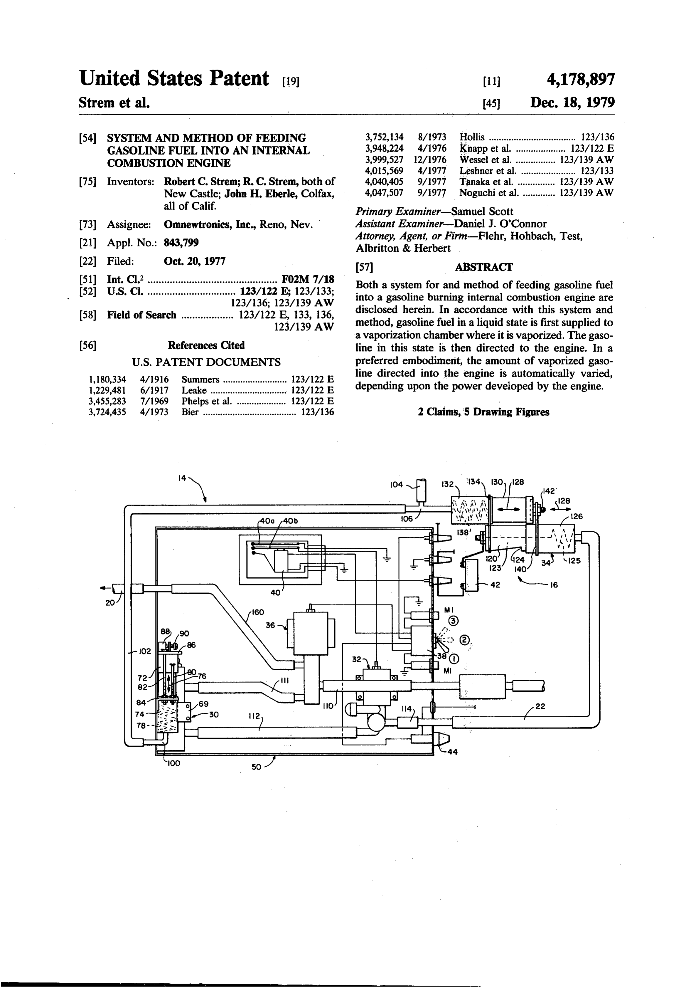
Both a system for and method of feeding gasoline fuel into a gasoline burning internal combustion engine are disclosed herein. In accordance with this system and method, gasoline fuel in a liquid state is first supplied to a vaporization chamber where it is vaporized. The gaso line in this state is then directed to the engine. In a preferred embodiment, the amount of vaporized gaso line directed into the engine is automatically varied, depending upon the power developed by the engine.
2 Claims, 5 Drawing Figures
Page 2
Drawing sheet — no readable text.
Page 3
Drawing sheet — no readable text.
Page 4
Drawing sheet — no readable text.
Page 5
for feeding gasoline fuel into a gasoline burning internal
SYSTEMAND METHOD OF FEEDING GASOLINE combustion engine.
FUEL INTO AN INTERNAL COMBUSTION Another object of the present invention is to provide ENGINE a system which improves upon gasoline usage in a gaso BACKGROUND OF THE INVENTION line burning internal combustion engine. Still another object of the present invention is to
The present invention relates generally to gasoline provide a system for feeding gasoline fuel into a gaso burning internal combustion engines and more particu line burning internal combustion engine, which system larly to a system for and method offeeding gasoline fuel 10 does not require a carburetor, but rather feeds directly into an engine of this type. into the intake manifold of the engine, thereby eliminat Today, a typical gasoline burning internal combus tion engine utilizing standard fuel feed apparatus re ing the various disadvantages resulting from the utiliza ceives liquid gasoline. In this standard apparatus, liquid tion of a carburetor.
gasoline is pumped into and through the engine's carbu 15 Yet another object of the present invention is to pro retor where it is mixed with air (atomized) and then vide a system of the last-mentioned type which can be ultimately through the intake manifold (through appro readily incorporated into an existing engine including a priate butterfly valves) and into the engine, the gasoline carburetor.
remaining liquid (theoretically atomized) before reach A further object of the present invention is to provide ing this point. This particular method has several disad a method of feeding gasoline fuel into a gasoline burn vantages. First, as the gasoline passes through the car 20 ing internal combustion engine, which method includes buretor the venturis within atomize the fuel, but only to the various objectives set forth above. a limited extent. As a result of the partial atomization, These objects, as well as other objects and features, the overall efficiency of the engine is reduced. Second, are achieved by the particular system and method of the even if total atomization is attained, it has been found present invention as will become apparent hereinafter. that this is never the less a relatively inefficient way to 25 In this regard, for purposes of description, both the combust the fuel.
There is still another disadvantage resulting from the present system and method will be described in relation utilization of conventional feed apparatus for gasoline to an internal combustion engine used for powering a burning internal combustion engines. This relates more vehicle, for example an automobile. However, it is to be to the manner in which the gasoline is fed into the en 30 understood that the present invention is equally applica gine rather than its particular state. More specifically, in ble where the engine is provided for powering or driv conventional feed apparatus, the amount of gasoline fed ing other apparatus. Moreover, fuels other than gasoline into the engine is dependent solely on what takes place may be utilized by the present invention and for pur at the fuel pump and associated throttle which is con poses of the present invention would be equivalent so trolled directly by the operator. Accordingly, at a given 35 long as they function in an internal combustion engine throttle position, for example half-throttle (half power), in the same manner as gasoline. Regarding this latter the same amount of gasoline will be fed to the engine, point, it should be clear that, for example, diesel fuel regardless of the needed power to be developed by the would not be such a fuel.
engine to maintain or exceed its RPM rating at that throttle position. In the event that the engine requires fuelInisaccordance with the present invention, gasoline more power and hence more fuel, for example in the collection chambera liquid supplied in where state from a supply tank to a it is vaporized and then di case of a vehicle powered by the engine, when the vehicle starts up a hill, this fuel will not be provided rected into the engine in this latter state. It has been unless the operator manually feeds more gasoline into found that vaporizing the gasoline results in more effi the engine, that is, increased the throttle. In a similar 45 cient combustion than when the gasoline to be com fashion, when the vehicle starts down a hill less power busted is partially atomized or even completely atom and hence less fuel is required and yet the amount of ized. Moreover, the carburetor which is used in a con fuel fed to the engine will not be reduced unless the ventional gasoline burning internal combustion engine operator manually does so by lowering the throttle can be eliminated, thus eliminating atomization of fuel level. It has been found that this required manual re 50 and partial atomization. Hence, the system and method sponse to changes in power and fuel requirement by the of the present invention provides more efficient utiliza engine also reduces the efficiency of gasoline usage. tion of fuel than does the conventional gasoline feed As will be seen hereinafter, the present invention systems utilized heretofore.
provides both a system for and method offeeding gaso In a preferred embodiment of the present invention, line fuel into a gasoline burning internal combustion 55 as will be discussed in more detail hereinafter, the va engine in a more efficient manner than heretofore at porized gasoline is automatically directed to the engine tainable by conventional feed apparatus. As will also be in varying amounts depending upon the power devel seen, this is accomplished by vaporizing the gasoline oped by the engine. More specifically, once the opera outside of the engine, prior to combustion, and, in a tor selects the desired throttle position to attain a certain preferred embodiment, this vaporized gasoline is auto matically delivered to the engine in varying amounts RPM operating condition, the necessary amount of fuel depending upon the power developed by the engine, required to maintain this condition is continuously and even though the throttle may remain in a fixed position. automatically fed into the engine without requiring the
OBJECTS AND SUMMARY OF THE
operator to continuously change the throttle position.
65 This is true even though the vehicle powered by the
INVENTION engine may be required to travel uphill from a level One object of the present invention is to provide an course (requiring more fuel) or it takes downhill course efficient and yet uncomplicated and economical system (requiring less fuel).
Page 6
BRIEF DESCRIPTION OF THE DRAWINGS amount of gasoline fed to the engine is made to increase proportionately with a decrease in vacuum level at the
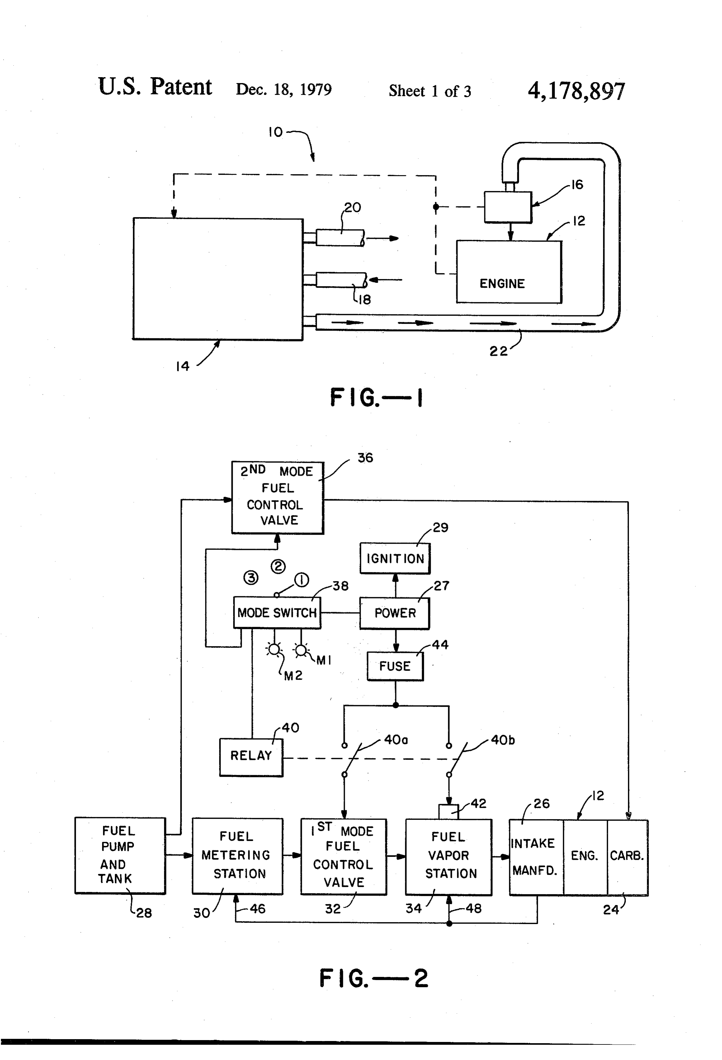
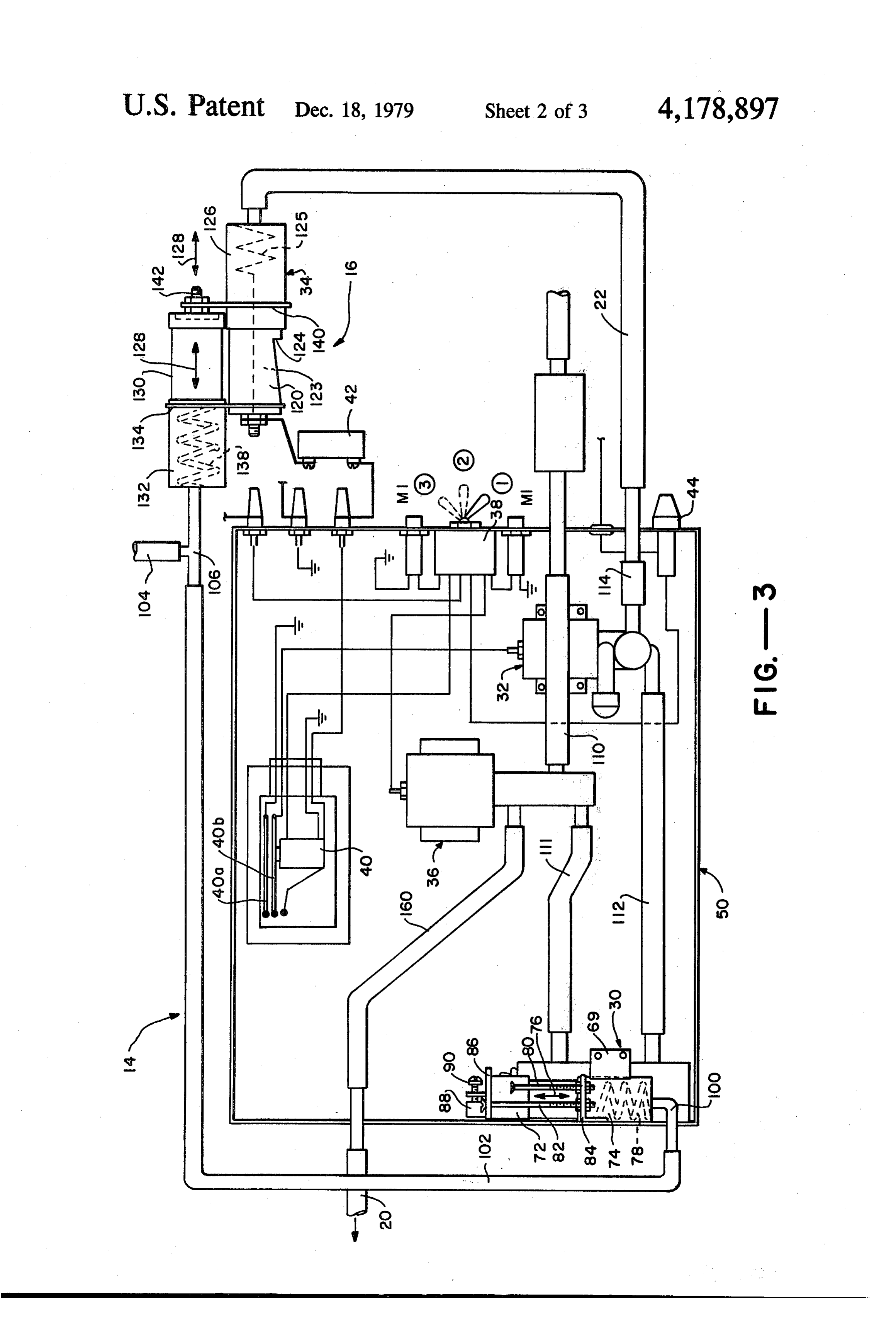
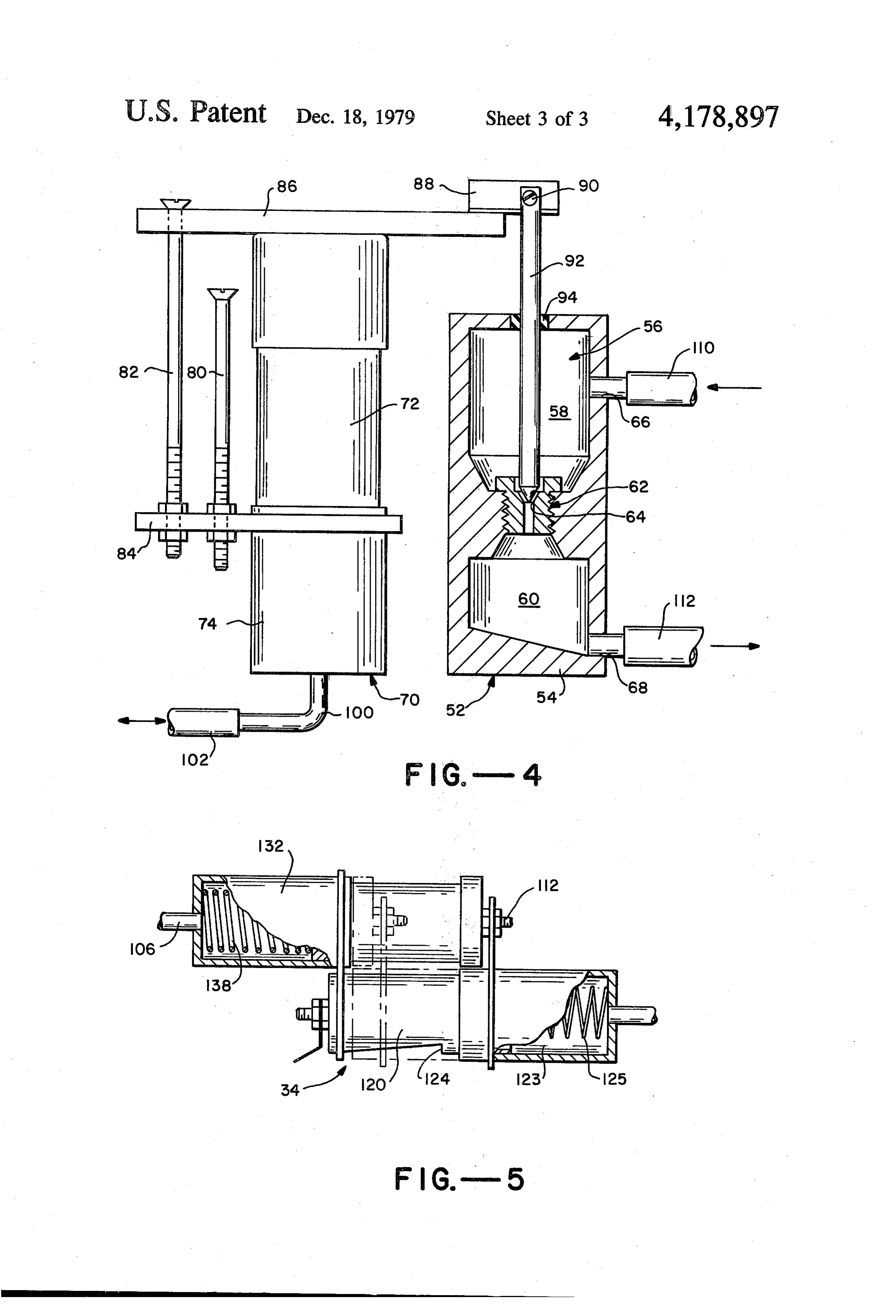
FIG. 1 is a block diagram of a system which has been manifold and it is made to decrease proportionately designed in accordance with the present invention and with an increase in vacuum level, i.e., the amount of which is provided for feeding gasoline fuel into a gaso gasoline fed to the engine is inversely proportionate to line burning internal combustion engine. the vacuum level at the intake manifold. Moreover, as FIG. 2 is a more detailed block diagram of the system stated previously, the vacuum level at the manifold is illustrated in FIG. 1. inversely proportional to the power developed by the F.G. 3 is a detailed schematic illustration of the sys engine. Therefore, the amount of gasoline fuel directed tem illustrated in FIGS. 1 and 2. O to the engine is directly proportional to the power it FIG. 4 is an enlarged schematic illustration of one of develops to meet a certain RPM demand which, in turn, the arrangements comprising part of the system illus depends upon the throttle position of the engine. trated in FGS. 1 to 3. Based on the foregoing, if the throttle is maintained in FIG. 5 is an enlarged schematic illustration of an an idle position, system 10 will provide the exact other arrangement comprising part of the system illus 15 amount gasoline fuel required by the engine to develop trated in FIGS. 1 to 3. sufficient power for running at the particular RPM DETALED DESCRIPTION rating for the idle position. At for example half throttle (half power), system 10 will provide the necessary
Turning now to the drawings, wherein like compo amount of gasoline fuel for running the engine to meet nents are designated by like reference numerals 20 this requirement. In this last example, it should be noted throughout the various figures, attention is first directed that until the vehicle driven by the engine gets up to to FIG. 1. This figure illustrates a system 10 which is speed (as determined by the throttle position) the engine designed in accordance with the present invention and will be required to develop more power than is neces which is provided for feeding gasoline fuel into a gaso sary once the vehicle reaches the desired speed. Hence, line burning internal combustion engine, generally des 25 until then, more fuel will automatically be fed to the ignated at 12. The engine itself may be of any conven engine and will automatically taper off as the power tional type which burns gasoline fuel and would include developed within the engine tapers, without changing all of the required components to make it function prop the throttle position. Thereafter, should the vehicle erly including internal components, for example an start a course up hill, more power will automatically intake manifold, and external but cooperating compo 30 develop within the engine which, in turn, will cause a nents such as a carburetor, a fuel pump and cooperating decrease in vacuum level at the manifold. Thus, an throttle and the like. In fact, as will be discussed herein increased amount of fuel will automatically be directed after, in accordance with one embodiment of the pres to the engine. In a similar manner, a down hill course ent invention, the internal combustion engine is of a will cause less fuel to be directed to the engine. conventional type which includes an intake manifold 35 Having described system 10 generally, attention is and which, when operating, draws a vacuum through now directed to FIG. 2 which illustrates the system in the manifold. The level of this vacuum depends upon more detail. As seen in this figure, engine 12 is shown the power developed by the engine, that is, it is in along with a carburetor 24, its intake manifold indicated versely proportional to the power developed by the at 26, a fuel pump supply tank, indicated generally at 28, engine. Hence, during an idle condition, (low power), 40 its ignition system indicated generally at 29 and a power the level of vacuum is high, for Example 21 inches of supply 27, for example a 12 volt automobile battery. mercury. At half power, the vacuum is at a lower level, While the engine's throttle as well as other conventional for Example 7 inches of mercury, and at full power the components associated with the overall engine system vacuum is at a minimum level, for example no vacuum have not been illustrated they would of course be in at all. 45 cluded where necessary to the overall operation of the For purposes of description, system 10 may be sepa engine.
rated into two subsystems, one of which is indicated at As illustrated in FIG. 2, system 10 includes what may 14 and the other which is indicated at 16. As will be be referred to as a liquid fuel metering arrangement 30 discussed in more detail hereinafter, subsystem 14 re adapted to receive liquid gasoline from the fuel pump ceives fuel from the fuel pump, specifically from the 50 and supply tank 28. At the output of fuel metering ar carburetor when one is provided via input hose 18. This rangement 30, system 10 includes a FIRST MODE fuel fuel is either applied directly back into the carburetor control valve 32 which is adapted to open and close a via output hose 20 or, in accordance with one aspect of line which directs fuel, again in a liquid state between the present invention, it is directed to subsystem 16 by a arrangement 30 and a fuel vaporizing arrangement 34. suitable hose 22. Each of these hoses may be an appro 55 This latter arrangement, as will be seen, vaporizes the priately sized nylon reinforced neoprene hose. Subsys liquid fuel received at its input and directs this vapor tem 16 provides an electrical heating coil or other suit ized fuel to the intake manifold 24 of engine 12. able means, as will be seen hereinafter, for vaporizing The various other components which are illustrated the gasoline it receives from subsystem 14. This vapor in FIG. 2 and which comprise part of system 10 include ized fuel is then applied directly to the intake manifold a SECOND MODE fuel control valve 36, a mode of the engine, bypassing the carburetor altogether, switch 38, a relay 40 and its associated relay contacts where it is combusted in the usual manner. 40A and 40B, and a thermostat or other suitable over In accordance with another aspect of the present ride switch 42 responding to temperature. In addition, invention, the amount of gasoline fuel directed to the system 10 includes an appropriately sized fuse 44 which engine is automatically varied to provide only the nec 65 is in circuit with the FIRST MODE fuel control valve essary amount to run it at the particular power it devel and also with an electrical heating coil comprising part ops. This is accomplished by utilizing the vacuum de of the fuel vaporizing arrangement 34, as will be seen veloped at the intake manifold. More specifically, the hereinafter.
Page 7
5 6 :
System 10 in its preferred embodiment has been de rangements 30 and 34 to deliver, simultaneously and in signed to operate in two modes. In its FIRST MODE, synchronism, less fuel to the engine. (position 1 on the switch) the system operates in accor When operating in the first mode, it is desirable to dance with the present invention for feeding an auto utilize the heat from engine 12 for vaporizing the liquid matically varied amount of vaporized fuel to the intake gas, of course where there is sufficient heat at the en manifold 26 of engine 12. In its SECOND MODE, gine, rather than using unnecessary power from battery (position 2 on the switch) system 10 feeds liquid fuel 27. To accomplish this, thermostat 42 is positioned in directly to carburetor 24. There is actually a THIRD line with the power supply, that is, the battery and the MODE, (position 3) that is a neutral mode, where nei heating coil to be described. This device 42 is located in ther of these two situations occur, that is, when the 10 close proximity to the heating coil so that when the engine is not operating. . . . temperature at the coil, resulting from the engine's heat, In order to operate in the FIRST MODE, that is the is sufficiently high to vaporize the incoming liquid gaso mode utilizing vaporized gasoline fuel, the mode switch line without the need for electrical power, the device 38 is appropriately positioned to the FIRST MODE 15 34. opens the circuit between battery 27 and arrangement (position 1) which closes an appropriate circuit to bat tery 27 for energizing an indicator light M1. At this In order to operate system 10 in its second mode of point in the operation of system 10, the relay 40 is in a operation for feeding liquid gasoline from the fuel pump deenergized state and its associated relay contacts 40A and supply tank directly into the carburetor in liquid form, the mode switch is first moved to its SECOND and 40B are in their opened positions, as indicated. 20 MODE position. With this switch repositioned, an ap Accordingly the FIRST MODE fuel control valve is closed (deenergized) and the fuel vaporizing arrange propriate circuit to the battery closes for energizing a second indicator light M2. Of course the circuit includ ment is inoperative, that is, its electrical heating coil is ing not energized. “. . . indicator light M1 is opened for deenergizing the In order to make system 10 operative in its first mode, latter. Now, with the engine not running and the igni the throttle position is selected by the operator, which is 25 tion valve system off, both the FIRST MODE fuel control and the SECOND MODE fuel control valve are usually the idle position during initial startup and the deenergized and hence prevent passage of gasoline. ignition system 29 is turned on. At this time, power is Once the ignition system is turned on, the circuit be delivered from battery 27 through mode switch 28 to tween battery 27 and the SECOND MODE fuel con relay 40 for energizing the latter. Energization of relay 30 trol valve 36 closes through mode switch 38, thereby 40 causes relay contacts 40A and 40B to close which in energizing this valve and opening up its associated line turn respectively cause the FIRST MODE fuel control for feeding liquid gasoline fuel directly into the carbure valve to energize and close and the heating coil in fuel vaporizing arrangement 34 to heat up. At the same time, tor from the fuel pump and the supply tank. This, of course, means that the gasoline bypasses fuel metering it should be noted that the SECOND MODE fuel con 35 station 30, trol valve 36 is in a deenergized, closed state, thus clos vaporizingFIRST MODE fuel control valve 32 and fuel arrangement 34. As will be best illustrated in ing the fuel line between the fuel pump and supply tank FIG. 3, the SECOND MODE fuel control valve not and the carburetor. only allows the passage of liquid gasoline from the fuel Having opened control valve. 32, liquid gasoline pump and supply tank directly into passes into the fuel metering arrangement 30, actually in its preferred form it also preventsthepassage carburetor, but into a chamber comprising part of the arrangement, as gasoline to the fuel metering arrangement. of liquid will be seen hereinafter, from the fuel pump and supply As described above, system 10 can operate in two tank 28. Arrangement 30 meters the fuel it receives in a effective controlled fashion to be described below through the invention,modes,i.e., the one in accordance with the present
FIRST MODE described above, and
FIRST MODE fuel control valve and into the fuel 45 also in a conventional mode, i.e., whereby liquid gaso vaporizing arrangement, again actually into a chamber line is fed directly into the engine via the carburetor, the comprising part of the arrangement. The liquid fuel SECOND MODE described above. In this regard, the received at arrangement 34 is vaporized by means of the preferred embodiment of the present invention has been previously referred to heating coil and fed, again in a designed for incorporation into an existing internal controlled fashion, into intake manifold 26 where it is 50 combustion engine. However, it is to be understood that eventually burned by engine 12. the system could be designed for use in a new engine In a preferred embodiment of the present invention, which does not include a carburetor and/or conven the amount of liquid fuel fed to fuel vaporizing arrange tional gasoline feed apparatus. In other words, system ment 34 automatically varies proportionately with the 10 could be designed without the SECOND MODE of power developed by the engine. In a similar manner, the 55 operation.
vaporized fuel fed to the intake manifold from the fuel . . . Having described system 10 and its method of opera vapor arrangement 34 automatically varies proportion tion, attention is now directed to FIGS. 3, 4, and 5 for ately with the power developed by the engine. This is a more detailed description of the various components accomplished, as will be seen with respect to FIG. 3, by ". . making up this system. As illustrated in FIG. 3, system making both arrangements 30 and 34 responsive to the 10 includes a housing or casing 50 for containing most vacuum level within intake manifold 26, as indicated by of the components making up system 10, with the ex the feedback arrows 46 and 48. It should suffice: now : ception of fuel vaporizing arrangement 34 and associ merely to state that as the power developed in engine 12 ated thermostat 42. Actually, it should become apparent increases, the vacuum within intake manifold: 24 de that the various components contained within the hous creases causing both arrangements 30 and 34 to deliver, 65 ing or casing 50 together make up the previously de simultaneously and in synchronism, more fuel to the scribed subsystem 14 while the fuel vaporizing arrange engine and as the engine develops less power, the vac ment 34 and its associated thermostat together make up uum within the intake manifold increases causes ar-, s the previously described subsystem 16.
Page 8
Turning to FIG. 4 in conjunction with FIG. 3, atten further downward movement of stop plate 86 and there tion is specifically directed to fuel metering arrange fore the piston and the head of screw 82 prevents futher ment 30. As illustrated, this arrangement includes a upward movement of these components. As will be seen liquid gasoline metering valve 52 comprised of a hous below, the positions of these screws determines the ing 54 which is mounted to and within casing 50 by 5 minimum and maximum amount of liquid fuel passing suitable means, for example a bracket 69 and which through valve 52.
defines a metering chamber 56. This chamber includes a Having described valve 52 and valve control assen top section 58 and a botton section 60 separated by bly 70, at least in part, attention is now directed to the means of an internal stationary jet 62. This stationary jet particular way in which this control assembly actually is actually a conventional valve seat which circum 10 controls the amount of liquid gasoline metered through scribes the inner wall of the chamber for defining a fixed the valve. Piston 72 carries with it a suitably connected passage 64 between the top and bottom sections of bracket or other such means 88 and associated support chamber 56. As will be seen hereinafter, liquid gasoline screw 90 which together fixedly support a vertically enters into the top section of chamber 56 through an downwardly extending metering rod (needle) 92 which appropriately sized inlet 66 and is metered through 15 is movable with the piston. As illustrated in FIG. 4, a passage 64 into bottom section 60 of the chamber in a bottom end section of this rod or needle extends into controlled fashion to be described, and finally the liquid chamber 56 and is vertically movable therein with gasoline passes out of the valve through an appropri movement of piston 72. In this regard, an appropriate ately sized outlet 68.
In order to control the amount of liquid gasoline 20 seal 94 is provided around the opening through which rod 92 passes for providing a seal at this entry point. As metered through valve 52, arrangement 30 includes a also valve control assembly 70 which is illustrated in both tapersillustrated, a bottom section of the rod or needle inwardly towards its bottom and is located in
FIGS. 3 and 4. This assembly includes a vacuum re valve seat 62 as illustrated. As the rod tends to move sponsive piston 72 and cooperating cylinder 74. As further towards illustrated in FIG. 3, the cylinder is mounted in a fixed 25 metering jet, thatthe
bottom section of chamber 56, the the opening through the valve seat position within and against casing 50 by any suitable becomes smaller, allowing less fuel to pass between the means, for example previously mentioned bracket 69 two compartments and as the which supports housing 52. As will be described in from the bottom section of therod moves up and further chamber, the jet enlarges detail below, piston 72, which is located above the cyl inder, is adapted for movement to a limited degree 30 allowing more liquid fuel to pass therebetween. It towards and away from the cylinder, as indicated by the should be apparent that valve 52 is similar, if not identi two-way arrow 76. In the embodiment illustrated, the cal, in operation to a conventional needle valve. In this piston is biased in its extended position, that is, a posi regard, any suitable means which achieves the same end tion away from cylinder 74 by suitable biasing means, as valve 52 may be provided.
for example a spring 78 located within the cylinder. 35 In the actual practice of the present invention, cylin Suitable means (not shown) may be provided for vary der 74 is connected to the intake manifold 26 of engine ing the amount of biasing force exerted by this spring. 12 through a vacuum line connector 100, a suitably Movement of the piston towards cylinder 74 to over sized vacuum hose 102, and a suitably sized vacuum come the biasing force exerted by sprint 78 is achieved hose 104. As illustrated in FIG. 3, vacuum hose 102 and by means of vacuum. More specifically, cylinder 74 is 104 are connected together by a tee connection 106. connected to a source of vacuum, specifically to previ The other end of hose 104 (not shown) leads to the ously discussed intake manifold 24, so that the closeness intake manifold. Accordingly, as the vacuum level at of piston 72 to cylinder 74 is directly proportionate to the intake manifold varies with the power developed by the vacuum level at the manifold, that is, the higher the the engine in the manner described previously, the posi vacuum level, the closer the piston is to the cylinder. : 45 tion of piston 72 will vary and hence so will the position For reason to be discussed hereinafter, the movement of rod 92 with respect to jet 62. More specifically, as the of piston 72 both towards and away from cylinder 74 is vacuum level increases (lower power), the piston moves limited to a predetermined extent. This is accomplished closer to the cylinder for reducing the amount of fuel utilizing a pair of vertically extending, spaced apart passing through valve 52. As the vacuum level de screws 80 and 82. As illustrated in FIG. 3, each screw 50 creases (more power), the piston moves further from 80 and 82 is thread mounted at one end through a coop the cylinder for increasing the amount of fuel passing erating thread opening in a support bracket 84 (or held through the valve.
in place by counternuts as shown) and held in an adjust Of course, the necessary calibration would have to be ably fixed vertical position. The support bracket is riv made to correlate the amount of gasoline passing eted or otherwise suitably connected to casing 50. It 55 through the valve with the vacuum level at the mani should be noted that screw 82 extends through what fold. This could be readily provided by those with ordi may be referred to as a stop plate 86 which is fixedly nary skill in the art. In this regard, the adjusting screw connected to the top of piston 72 for movement there 80 is positioned such that when the engine is idling with. Also note that the head of screw 82 is located (maximum vacuum level) the rod or needle is in its above the head of screw 80 and also above stop plate 86. downward most position (the stop plate rests against the Further, note that the opening in stop plate 86 through top of screw 80) to allow a predetermined, minimum which the shank of screw 82 extends is sufficiently large but sufficient amount of fuel to pass through chamber to allow movement of the stop plate along the shank of 56. Screw 82 is positioned such that when the engine the screw but is sufficiently small to prevent movement develops full power so that there is a minimum, if any, passed the head of the screw. Hence, it should be 65 vacuum at the manifold, the rod 92 is in its upward most readily apparent that stop plate 86 limits the movement position (the stop plate rests against the underside of the of piston 72 to the vertical distance between the heads head of screw 82) for allowing the desired maximum of the screw 80 and 82. The head of screw 80 prevents flow of liquid fuel through the chamber.
Page 9
As stated previously, the liquid gasoline is directed to is, the greater the vacuum level the closer the piston 130 arrangement 30 from fuel pump and supply tank 28 and 3. is to cylinder 132 and the further it is from its biased is directed on to and through the first mode fuel control position (minimum vacuum).
valve 32. This is accomplished by utilizing a number of As seen in FIG. 5, a tie rod or other such means 140 interconnected fuel hoses generally indicated at 110 for 5 is provided for interlocking slide cover 126 for move connecting the fuel pump to inlet 66 in valve 52 of . ment with piston 130. In this manner, as the piston arrangement 30 and a hose 112 for connecting the outlet moves towards its extended or biased position (mini 66 of this valve to the inlet of FIRST MODE fuel con mum vacuum, maximum power), the slide cover moves trol valve 32. . . . . . away from vent 124 so that the vent can be opened to As illustrated in FIG. 3, valve 32 is a conventional 10 the fullest extent desired (maximum level). On the other solenoid operated fuel control valve which when deen hand, as the piston moves towards its associated cylin ergized is closed and when energized is open. This der, under the influence of vacuum developed in the solenoid valve, as illustrated, is electrically connected intake manifold, the slide cover 126 moves towards the through previously described normally closed contact end of housing 120 containing vent 124 for progres 40A of electromagnetic relay 40 and fuse 44 to a suitable 15 sively reducing the size of the vent in proportion to the source of power, for example battery 27. While the level of vacuum developed within the intake manifold. various electrical lead wires for making these connec The position of slide cover 126 relative to vent 124 can tions have been illustrated, at least in part, references be adjusted by any suitable means, for example an ad thereto will not be made. It should be quite obvious to justment screw 142 used to adjust the position of tie rod those with ordinary skill in the art exactly how the 20 140. In an actual working embodiment, the slide cover various components are electrically connected to one would be adjusted so as to allow a minimum amount of another to operate in the manner described. fuel to pass out vent 124 when the vacuum level within As just stated, the input to solenoid valve 34 is cons the engine is at a maximum (the idle position) and the nected to the output of arrangement 30 by means of slide cover would be positioned to allow maximum flow hose 112. The output of solenoid valve 34, as illustrated 25 of fuel through the vent when the vacuum level is at a in FIG. 3, is connected to one end of previously men minimum (full power). In any event, the appropriate tioned hose 22, by means of a hose connection 114 and amount of vaporized gasoline in the chamber 123 of suitable clamps (not shown). The other end of hose 22 is . housing 120 is drawn through vent 124 and into the connected to the input of fuel vaporizing arrangement intake manifold by engine 12.
30 As stated previously, arrangement 34 includes heat
Turning to the details of arrangement 34, attention is ing coil 125. This heating coil is of course provided for directed to FIG. 5 in conjunction with FIG.3. As illus vaporizing the liquid gasoline as it passes into housing trated in these figures, fuel vaporizing arrangement 34 120. As illustrated in FIG. 3, subsystem 16 may include includes a longitudinally extending housing 120 which 3, previously referred to thermostat 42. This thermostat is is fixedly mounted in place by suitable means (not 35 connected in line with the heater and power supply and shown), which defines an internal chamber 123 and would be physically located adjacent housing 120, so as which includes a vent 124 extending in an outwardly to deenergize the heating coil 125 in the event the tem tapered fashion from one end of the housing towards perature at the housing developed by engine 12 is suffi but stopping short of its opposite end. A 12 volt heating ciently high in by itself to vaporize the liquid gasoline as coil 125 is located within housing 120, near the end of 40 it enters the housing. The exact amount of heat required the housing opposite vent 124 and is appropriately ener to vaporize the gasoline and the setting of thermostat 42 gized through relay contact 40B and fuse 44 by means . . could be readily determined by those with ordinary skill of battery 27, as stated previously. Again, the appropri in the art. Once chamber 123 is heated to the required ate electrical leads to accomplish this while shown in temperature, whether by the heater or the engine's heat, part will not be discussed. A longitudinally extending 45 the liquid gasoline passing therethrough will vaporize. slide cover 126 (approximately one-half, the length of In this regard, it should be noted that combustion within housing 120) is concentrically located over a longitudi chamber 123 will not take place so long as there is insuf nal segment. of housing 120 and is slidably movable. ficient oxygen within the chamber or the fuel passes along the housing, as indicated by the two way arrow through it too fast. During idle condition even though 128. As will be seen below, this slide cover is provided 50 the gasoline does not pass through chamber 123 rapidly, for varying the size of vent 124 for varying the amount the effective opening of vent 124 is quite small and of vaporized gasoline passing through the vent. hence prevents sufficient oxygen to support combus Arrangement 24 also includes a vacuum responsive tion. Where the vent opening is larger (higher fuel con piston 130 and associated cylinder 132 identical, at least sumption), the gasoline passes through the chamber too in operation, to previously described piston 72 and asso 55 fast to support combustion therein. ciated cylinder 74. As illustrated in FIG. 5, the cylinder Having described fuel vaporizing arrangement 34, is fixedly mounted in place to housing 120 by suitable the only remaining component of the system 10 to dis means, for example bracket 134 and is operatively con cuss in detail is the SECOND MODE fuel control nected to the intake manifold through tee connection valve 36. As illustrated in FIG. 3, this valve is solenoid 106 and vacuum hose 104. The piston 130 on the other operated and is connected in circuit through switch 38 is free to move between an extended position closer to to battery 27 when the switch is in its SECOND the cylinder. The piston is biased in its extended posi- , MODE position. The input of the valve is connected in tion, that is, away from the cylinder by any suitable line with the series of hoses 110 and its output is con means such as return spring 138 located within cylinder : nected directly to the carburetor through a hose 160 132. The amount of the movement of the piston towards 65 which in turn is connected to previously, referred to the cylinder overcoming the forces supplied by spring . . hose 20. When switch 38 is in a position other than its 138 is calibrated to be directly proportional to the level. SECOND MODE, the solenoid actuated valve remains of vacuum within the intake manifold of the engine, that deenergized for closing the path of fuel between the fuel
Page 10
pump and carburetor (hose 110 remains open through vaporized state to pass through the system into the this valve). Upon placing the switch in SECOND engine. Once the engine reaches the rated speed as MODE, the solenoid energized opening up the line determined by the throttle position, less power is neces between the fuel pump and carburetor. It should be sary to maintain the rated speed and hence the power pointed out that since the switch is in this second posi developed will drop to a lower level causing the vac tion, the previously described control valve 32 remains uum level at its intake manifold to drop, thus automati closed. Accordingly, system 10 in this second mode of cally reducing the amount of fuel fed through system operation allows the engine 12 to be fed gasoline fuel in 10. This is carried out automatically regardless of the the conventional manner, bypassing the fuel metering fact that the throttle is left in its original position. This station and the fuel vaporizing station. In this regard, it 10 is because both arrangements 30 and 34 respond to the should be noted that a conventional valve 36 can be level of vacuum in the engine and not merely to the provided that will open the line from the fuel pump to throttle position itself.
the carburetor and at the same time automatically close The manner in which system 10 operates in its SEC the line 110 from the fuel pump to fuel metering ar OND MODE should be self-explanatory. With the rangement 30. 5 switch in its SECOND MODE position, the valve 36 is
As noted above, a detailed description has been pro energized while the relay coil 40 and valve 32 are deen vided for the fuel metering arrangement 30, FIRST ergized. This means that gasoline in its liquid state goes MODE fuel control valve 32, fuel vaporizing arrange directly from the fuel pump back into the carburetor ment 24 and SECOND MODE fuel control valve 36. It bypassing both arrangements 30 and 34. is believed that a detailed discussion of the other com- 20 What is claimed is:
ponents making up system 10 is unnecessary. It should 1. A system for feeding gasoline fuel into a gasoline suffice to state that the relay 40 and its associated burning internal combustion engine which includes a contacts, the mode switch 38 and the fuse 24 are all conventional components suitably mounted within or to carburetor operating and an intake manifold and which, when draws a vacuum through said manifold, the casing 50 and appropriate interconnection with one 25 level of said vacuum being inversely proportionate to another and with the components described in detail to the power developed by the engine, said system com function in the manner described.
Turning now to the overall operation of system 10, prising: (a) a first gasoline collection chamber; let it first be assumed that the engine is not running, the ignition system is off and the selector switch 38 is placed 30 (b)state a first supply line for supplying gasoline in a liquid to said first collection chamber;
in the FIRST MODE of operation. In this particular (c) means including a pneumatically operated piston situation, the indicating light M1 is energized and with and cylinder arrangement connected with said the engine not running the vacuum level at the intake manifold is at its lowest level, specifically actually no intake manifold and responsive to the vacuum level vacuum at all. Hence, the valve 52 comprising part of 35 thereat for automatically varying the gasoline pass the fuel metering arrangement 30 is in its fully opened ing out of said first chamber in an amount which is position as is the vent 124 comprising part of arrange inversely proportionate to the vacuum level at the ment 34. However, fuel does not flow through these manifold;
arrangements because solenoid actuated valve 32 is (d) a second collection chamber; deenergized and hence closed. (e) a second supply line for directing the liquid gaso Let it now be assumed that the engine is to be started line passing out of said first chamber to said second and run in its idle position (lowest throttle level). Once chamber; w the ignition system is turned on, this energized relay 40 (f) electrically energized heating means located for closing both contacts 40A and 40B. Closure of within said second chamber for vaporizing the contact 40A causes the FIRST MODE fuel control 45 liquid gas therein;
valve to energize for opening the line between hoses (g) means including a second pneumatically operated 112 and 22. At the same time, the closure of contact 40B piston and cylinder arrangement connected with causes the coil 125 to heat up. As the engine idles, it said intake manifold and responsive to the vacuum develops a maximum vacuum at the intake manifold, for level thereat for automatically directing the vapor example 21 inches of mercury. In response to this high 50 ized gasoline into said intake manifold in an amount vacuum level, the liquid fuel control valve 52 closes to which is inversely proportional to said vacuum the maximum amount adjusted for by screw 80 to allow level;
the minimum amount of liquid fuel therethrough. At the (h) a first electrically actuated valve located in one of same time and in synchronism therewith, the sleeve 126 said supply lines for opening and closing said line; moves to its extreme position over vent 124 for provid 55 (i) a third supply line for supplying liquid gasoline ing only the minimum amount of vaporized gasoline from said supply tank to said carburetor, said third therethrough. This gasoline is of course directed actu line bypassing both of said chambers, whereby said ally drawn into the engine for maintaining the engine in gasoline enters said engine without first being va its idle position. porized;
Assume now that the operator desires to run the (j) a second electrically actuated valve located in said engine above its idle position. Movement of the throttle third supply line for opening and closing said third to a second position, for example a half throttle or full line;
throttle position, causes the engine to develop more (k) an electrical power supply; and power which in turn reduces proportionately the vac (l) means for alternatively connecting said power uum within the manifold. This in turn causes the valve 65 supply 52 to open and vent 124 to open proportionately and in (i) to said first valve and heating means for energiz synchronism with one another, thereby allowing more ing said first valve to open said first and second gasoline, both in its liquid state and ultimately in its supply lines and to energize said heating means,
Page 11
while maintaining said second valve de-ener inversely proportional to the vacuum level at gized to maintain said third line closed, and said manifold, and (ii) to said second valve for opening said third (ii) automatically directing the vaporized gasoline supply line while maintaining the other lines into said intake manifold in an amount which is closed and said heating means de-energized. 5 inversely proportional to said vacuum level; 2. A system for feeding gasoline fuel into a gasoline (g) a first valve means located in one of said supply burning internal combustion engine which includes a lines means for opening and closing the latter; carburetor and an intake manifold and which, when (h) a third supply line means for supplying liquid operating draws a vacuum through said manifold, the 10 gasoline from said supply tank to said carburetor, level of said vacuum being inversely proportionate to said third line means bypassing said collection area the power developed by the engine, said system com and said vaporization chamber, whereby said gaso prising: line enters said engine without first being vapor (a) a liquid gasoline collection area; ized;
(b) first supply line means for supplying gasoline in a 15 (i) line a second valve means located in said third supply means for opening and closing said third line liquid state to said first collection area; means; and (c) a liquid gasoline vaporization chamber; () means for alternatively (d) second supply line means for directing the liquid (i) actuating said first valve means to open said first gasoline passing out of said liquid gasoline collec and second supply line means, while maintaining tion area to said vaporization chamber; 20 said second valve means deactuated to maintain (e) means located within said vaporization chamber said third line means closed, and for vaporizing the liquid gas therein; (ii) actuating said second valve means for opening (f) means connected with said intake manifold and said third supply line means while maintaining responsive to the vacuum level thereat for said first valve means deactuated to maintain the (i) automatically varying the liquid gasoline passing 25 first and second lines closed. out of said collection area in an amount which is k . . . .
Provenance
- Collection
- Patents citing this work
- Pages
- 11
- Method
- pdftotext (the PDF's own text layer) + pdftoppm 300dpi page scans
- Patent office record
- patents.google.com →
- Source
- Google Patents citing-documents table
- Assignee
- Omnewtronics, Inc.
- Published
- 1979-12-18
- Transcribed from
- patentimages.storage.googleapis.com →