patent · US2197236
Fuel feeding means for internal combustion engines and the like
16 April 1940
Page 1
Drawing sheet — no readable text.
Page 2
Patented Apr. 16, 1940
UNITED STATES PAT ENT OFFICE
FUEL FEEDING MEANS FOR INTERNAL COM
BUSTION ENGINES AND THE LIKE
Cecil L. Bowen and John A. Bowen, Pueblo, Colo.
Application March 30, 1938, serial No. 198,834
The present invention relates to internal com trol means for regulating the components, name bustion engines, and more in particular to a fuel ly, gaseous hydrocarbon fuel and combustible generator therefor.
Among the objects of the present invention is medium engine. being supplied to the intake for the 5 to provide a fuel generator for an internal com Other objects, features, capabilities and ad bustion engine, which generator is of a simplified vantages are comprehended by the invention, as construction and is in heat association preferably will later appear and as are inherently possessed
enginethe exhausttheofhydrocarbon whereby the internalfuelcombustion conveyed Referring to the drawing: . . . . . . . .
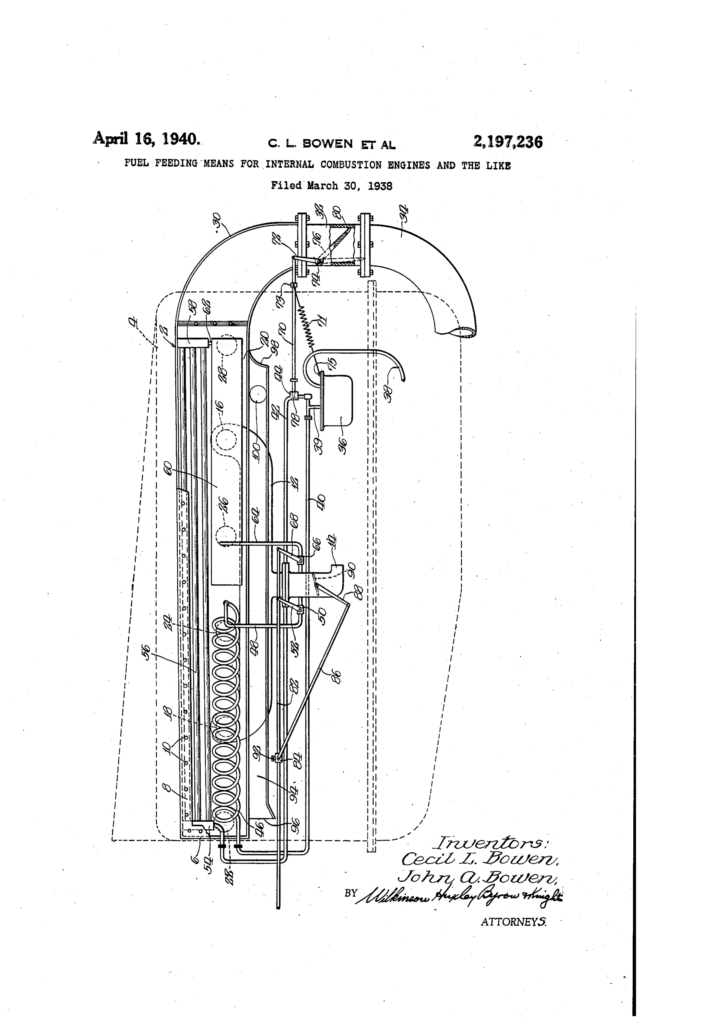
10 thereto is volatilized and properly mixed with a . The figure is a fragmentary view in side ele 0. combustion supporting medium for operating the vation of a gas generator embodying the present combustion engine.
Another object of the present invention is to invention, certain parts thereof being broken away to disclose more in particular the specific provide a novel gas generator for internal com arrangement of other of the parts thereof. l bustion engines which is adapted to economically Referring now, more in detail to the drawing, 15 and efficiently generate hydrocarbon fuel there an embodiment selected to illustrate the present for at all speeds. invention is represented generally as 2, the same More particularly, the present invention has to being connected to an internal combustion en do with a novel gas generator for internal com gine casing as shown in dotted lines 4...More 20 bustion engines, which generator comprises aux particularly, the novel device disclosed in the 20 iliary and main parts in heat association with drawing is enclosed in part in a manifold hous the internal combustion engine, the auxiliary unit ing 6, provided on the outer...face with a .re being adapted for generating hydrocarbon fuel movable plate 8 for access to the interior thereof, for initially starting the engine and to maintain this plate being secured to the housing in any 25 uniform idling running conditions for the inter desired manner, as for example, by bolts. O, or 25 nal combustion engine, and the main generator the like. This manifold housing is secured to unit being used for generating hydrocarbon fuel One side of the engine casing 4 and comprises for the engine when running from idling to in part an intake manifold f2 having an inlet maximum speeds. 4, the same communicating with intake ports 30 Still a further object of the present invention is to provide novel means in association with the a6,hydrocarbon and 8, each of which is adapted to supply 30 fuel generating means, and more particularly the engine. This fuel mixture to two cylinders of housing 4 is further provided
Connected to the main generating unit, for con With an interior elongated ditioning the gaseous hydrocarbon fuel and for chamber 20 which is 35 maintaining uniformity of pressure in the main in communication with exhaust ports 22, 24, 26 and 28 of the engine, one each being provided fuel line to the intake manifold. The invention for each cylinder thereof whereby the exhaust 35 Comprehends a chamber in heat association with gases are discharged into the manifold housing the engine and connected to the main generator 6 and expelled through an elbow 30 which, and intake manifold, which chamber acts in the through the fitting 32 connected thereto, dis 40 capacity of a surge tank for maintaining uni charges the gases into the exhaust pipe 34 also 40 formity of pressure and mixture and for condi connected to the fitting 32, and which pipe ex tioning by Way of a drying operation to supply tends rearwardly of the engine in the conven dry volatile gaseous fuel to the intake manifold, tional manner and is connected to a muffler dis . . this tank being adapted for use with or without posed beneath the vehicle body. 45 the auxiliary generator. As in the conventional type of automotive in 45 The invention further contemplates a novel ternal combustion engine, the pump 36 is pro control for cutting in and out the main fuel vided adjacent the casing 4, which fuel pump generator from the fuel supply in accordance is supplied with a fuel through line 38 extending with the operation of the engine. Such novel to a Source of supply usually at the rear of the 50 control may be operated in accordance with the vehicle, this fuel pump 36 being of any desired 50 Wolume of exhaust gases from the engine, or by construction and conventionally operated by a positive connection with the accelerator. . . means of the engine. .. . Still another object within the purview of the The present invention is directed more in par present invention is to provide in combination ticular is with the fuel generators novel combustible con from thetopump the generation of hydrocarbon fuel 36 for all driving operations, and
Page 3
the novel controls associated therewith for se proportion as to maintain this uniformity of curing uniform operation of the internal com pressure and to effectively and completely dry bustion engine under all conditions without ex the gaseous hydrocarbon fuel to prevent delivery cessive consumption of Such fuel and for securing of gaseous hydrocarbon fuel in a wet condition maximum efficiency of the device. to the intake manifold 2. This is an important It has been found that such desiderata are feature of the present invention and has been Incre closely approached if the fuel generator found to operate effectively and efficiently under is formed in two parts, one of which is used as all conditions.
an auxiliary generating unit for starting and for The valve 44, as referred to hereinbefore, is lo 10 idling speeds, and the other part, the main gen cated in the supply line 42 which extends by way O erating unit, for use in generating the hydro of the line 38 at one end to the fuel pump 36 carbon fuel for speeds above the idling speed. and at its other end to the main fuel generator. In the illustrative example of the invention, The needle for this valve 44 is in the form of an the fuel pump 36 is provided with a conduit 39 the elongated member 7 mounted and slidable in 5 s connected to conduit 49 and to a branch conduit casing of the valve 44 at one end and extend 42 having a needle valve 44 connected therein and ing at is other end and being pivotally connect which is operated under certain conditions, as ed to an arm or lever 2 fixed to a pivot 14 in Will be hereinafter more fully discussed. The the fitting 32 of the exhaust line. Mounted upon feed line 4 is connected to an auxiliary gen the pivot 74 is a flap valve 6 adapted, in its 20 20 erator 6 in the form of a coil of some desirable normal position, to extend across the opening metal which is highly responsive to heat condi of the fitting 32. The seating of member 70 with tions for quickly and efficiently volatilizing hy valve seat 78 and the normal positioning of the drocarbon fuel supplied thereto from the pump flapconnected valve 76 are obtained by way of a coil spring at one end to the collar 73 mounted 38. This auxiliary generator is disposed within 25 the manifold housing 6 in heat association with on the member T G and at the other end to the the exhaust gases from the engine and is rela fuel pump as at 5. When in this position the tively short in length as compared to the length adjustment of the member 9 is such that the of said manifold housing, the other end of the same is in seating relation with the valve seat same being connected by way of a pipe or lead 78 of the valve 44, thereby preventing flow of 30 30 48 to the intake manifold 2, this line 4S being hydrocarbon fuel from the pump 36 to the main provided with a valve 50 controlled by a lever fuel generator by way of line 2. In other words, or arm 52, as will be hereinafter more fully the flap valve :6 controls the fuel supply to the main fuel generator. This valve 6 is formed discussed.
The line 42 from the fuel pump 36 extends to with a cut-out portion 89, preferably V-shaped, which is just sufficient to allow the escape of 35 35 Ward the rear of the casing 4 and is connected to exhaust gases from the engine therethrough into One header 54 of the main generator, which com pipe 34 when the engine is at idling speed. prises a plurality of elongated tubular mem bers 56 connected to the header 54 at one i84Itmay is understood, however, that if desired, valve be cut in and out by means of linkage be end and to the opposite header 58 at the other tween rod 70 and the rod 82, hereinafter more 40 ib end, all of which is disposed within the manifold fully described.
housing 6 in heat association with the exhaust Connected adjacent the upper end of arms or gases from the internal colnbustion engine which level's 52 and $8 is a rod 82 extending to the are discharged through the ports 22, 24, 26 and rear of the motor and which is suitably connect 23 whereby, under certain conditions, hydrocar ed to the accelerator pedal on the floor of the 45 45 bon fuel from the pump 36 is volatilized in its passage through the tubes 56. vehicle body whereby levers 52 and 68 are op Disposed within the manifold housing 6 and at erated by movement of the accelerator foot pedal. Connected to the rod 32 through block 84 is a rod the end of the auxiliary generator coil 46 is an 86 having its other end connected to arm or level elongated Surge tank 6 connected adjacent one 88 controlling butterfly valve 90 of the intake 50 50 end thereof through the pipe 62 to the header 58 manifold. Block 84 is adjustable on rod 82 by of the main fuel generator and adjacent the means of the set-screw 92 to vary the position other end to the line 64 which is connected to the intake manifold 2, a valve 66 being provided of the butterfly valve 90 in the intake manifold and to vary the relative position of said valve therein for regulating the discharge of volatilized hydrocarbon fuel into said intake manifold by and said levers 52 and 68 of the valves 5 and 66 55 55 whereby any desired proportioning of gaseous way of an arm or lever 68 operated as will be here hydrocarbon fuel to the combustion supporting inafter more fully disclosed.
It is understood, of course, that the tank 6) is medium 4taken into the intake manifold through disposed within the manifold housing 6 in heat intake may be secured.
In order to secure added efficiency of the pres 60 .80 association with the exhaust gases for condi tioning the gaseous hydrocarbon fuel delivered ent device and more uniform and even operation thereof, the manifold housing 6 is formed with thereto from the tubes 56 of the main generator. an
This tank 60 providing an enlarged chamber as atelongated
chamber 94 opened to the rear closed to the front, as at 98, such serves to completely dry the hydrocarbon fuel de chamber being provided with an opening f OO to 65 5 livered thereto so that when such hydrocarbon which is connected a flexible hose connection or fuel is delivered to the intake manifold through the line 64, the same is in a superheated condi tubing (not disclosed) extending and being con tion, which increases the efficiency of operation supportingthe nected to intake 4 whereby the combustion medium for the gaseous hydrocarbon of the internal combustion engine. Further
O more, this tank also serves as a surge tank to as fuel is in a preheated state, it being understood,
of course, that the air in chamber 94, is in sure uniform pressure of the gaseous hydrocar association with the exhaust gases of the internal heat bon fuel delivered through the line 64 to prevent combustion engine.
uneven or erratic operation of the engine. In For the purpose of describing the operation this connection, the relative cross-sectional areas of the present device, assume that the motor is 75 s of the tubes 56 and the tank 60 are of such a
Page 4
cold when the operator steps on the starter to during idling speeds, but would be highly waste turn the same over for starting. Upon turning over of the motor, the pump 36 is operated to ful. With the present combination, however, of draw fuel from the line 38 and to discharge the auxiliary and main generator units, any desired same through line 4 to the auxiliary generator speed of operation can be obtained with Smooth coil 46, it being clearly understood that at this running of the engine and with economical con time the flap valve 76 is in the position shown Sumption of the hydrocarbon fuel. because of the fact that no pressure is built up While we have herein described and upon the drawing shown an illustrative embodiment of the 10 Thethe on motor side thereof by the exhaust gases.
auxiliary coil generator 46 immediately Sup invention, it is to be understood that the inven plies gas to the intake manifold f2, which gas is tion is not limited thereto but may comprehend 10 Sucked by vacuum from the motor into the in other constructions, arrangements of parts, de take ports 6 and 8. As the motor warms up tails and features without departing from the the exhaust gases. Surrounding the generator coil spirit of the invention. 15 46 more efficiently volatilize the hydrocarbon fuel We claim:
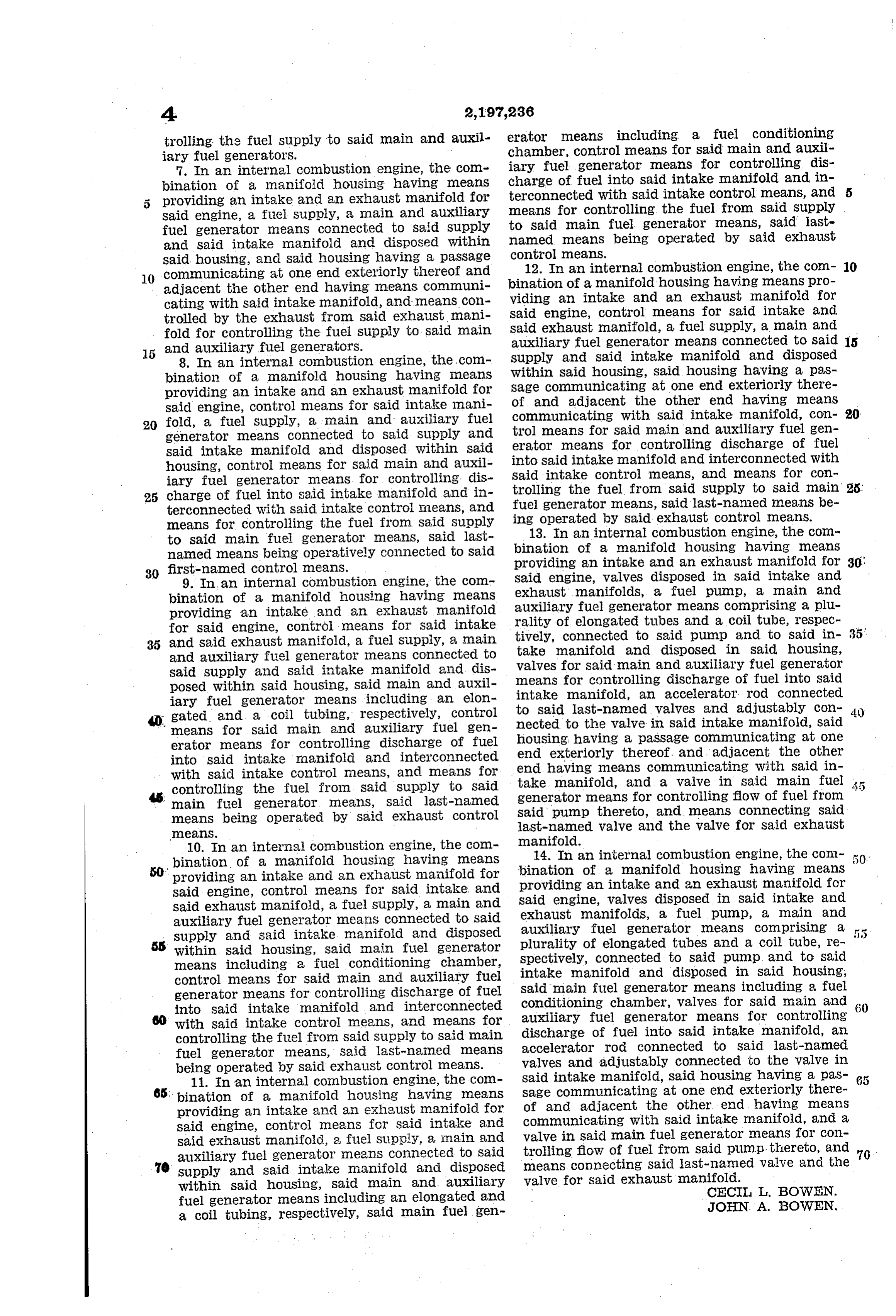
to provide for Smoother operation of the engine 1. In an internal combustion engine, the com bination of a manifold housing, means associ during its idling period. This initial starting of ated course heats the generator tubes 56 of the main haustwith said housing providing intake and ex manifolds for said engine, a fuel supply, generator so that the hydrocarbon fuel which 20 may be disposed therein at the time that: the a fuel generator means connected to said supply motor was last shut off will be volatilized and in and Said intake manifold and being in heat a condition to be discharged into the intake transfer association with said manifold housing, manifold when the conditions are such that fuel said last-named means including a fuel condi to be fed therefrom is desired. During this idling tioning chamber, an air passage in heat associa 25 period the flap valve 6 maintains its normal po tion with Said housing, and means connecting sition, as shown in full lines, in view of the fact said air passage with said intake manifold. 25. that no pressure is built up on the engine side 2. In an internal combustion engine, the com thereof due to the escape of exhaust gases through bination of a manifold housing having means pro the opening 88. Viding an intake and an exhaust manifold for said 30 This motor can be operated under idling con engine, a fuel supply, a fuel generator means ditions as long as it is desired, but when the op connected to said supply and said intake mani 30. erator steps upon the accelerator pedal, rod 82 is fold and disposed within said housing, said last moved to the right, as shown in the figure, to named means including a fuel conditioning cham feed a greater amount of gas to the engine, in ber disposed within said housing, and said hous
creasing its Speed, which at the same time be ing having a passage communicating at one end 35 cause of the exceSS Volume of exhaust gases, exteriorly thereof and adjacent the other end builds up pressure on the motor side of flap valve having means communicating with said intake 6 to open the same, which in turn opens valve 44 manifold.
through the needle member 70. Increased speed 3. In an internal combustion engine, the com 40 of operation of the motor affects the pump 36 bination of a manifold housing, means associated So that a greater amount of hydrocarbon fuel with said housing providing intake and exhaust is supplied through the line 42 to the main gen manifolds for said engine, a fuel supply, and erator tubes 56. This fuel is immediately vola main and auxiliary fuel generator means con nected to said supply and being in heat associa tilized in passing through the tubes and is finally 45 discharged into the surge or conditioning tank tion with said housing, said main fuel generator 68 whereby the same is supplied through line 64 means including a fuel conditioning chamber. . and valve 66 which is opened to the intake mani 4. In an internal combustion engine, the com fold 2. bination of a manifold housing having means Where it is found desirable to positively con providing an intake and an exhaust manifold for 50 nect valve 44 with rod 82 by means of linkage, said engine, a fuel supply, a main and auxiliary valve 44 is opened to supply the main generator fuel generator means connected to said supply () upon speeding up of the motor by movement of and Said intake manifold and disposed within said rod 82. housing, and means controlled by the exhaust It will therefore be quite apparent from the from Said exhaust manifold for controlling the 55 above description of the operation of the device fuel Supply to said main and auxiliary fuel gen that under idling speeds, say up to 15 or 20 miles, erators. 55. that the auxiliary coil generator 46 will supply 5. In an internal combustion engine, the com the fuel requirements for the engine, but that bination of a manifold housing having means pro after such speed has been passed, the main gen Viding an intake and an exhaust manifold for said 60 erator is ut in through valve 44 to supply a engine, a fuel supply, a main and auxiliary fuel greater quantity of hydrocarbon fuel for proper generator means connected to said supply, and 6 operation of the engine. This auxiliary coil has said intake manifold and disposed within said been found to be highly advantageous in a de housing, Said main fuel generator including a fuel vice of this kind inasmuch as the same is rela conditioning chamber, and means for controlling tively small in cross-sectional area, as compared the fuel supply to said main and auxiliary fuel to the main generator unit and is more respon generators. 65., sive to heat of the exhaust gases (because of its 6. In an internal combustion engine, the com material and wall thickness) so that more effec bination of a manifold housing having means tive volatilization is secured in Said auxiliary providing an intake and an exhaust manifold for 70 coil than could be obtained in the main genera said engine, a fuel supply, a main and auxiliary tor. This also assists in starting the motor in generator means connected to said supply 76 : that if reliance were placed upon the main gen fuel and said intake manifold and disposed within said erator in the starting operation, slugs of raw housing, said main fuel generator including a fuel gasoline would be supplied to the motor which conditioning chamber, and means controlled by 75 would not only cause the motor to run erratic the exhaust from said exhaust manifold for con- 75,
Page 5
trolling the fuel supply to said main and auxil erator means including a fuel conditioning chamber, control means for said main and auxil iary fuel generators.
7. In an internal combustion engine, the com iary fuel generator means for controlling dis charge of fuel into said intake manifold and in bination of a manifold housing having means providing an intake and an exhaust manifold for terconnected with said intake control means, and 5 Said engine, a fuel Supply, a main and auxiliary means for controlling the fuel from said supply fuel generator means connected to said supply to Said main fuel generator means, said last and Said intake manifold and disposed within named means being operated by said exhaust Said housing, and Said housing having a passage control means.
10 Communicating at One end exteriorly thereof and 12. In an internal combustion engine, the com- 10 adjacent the other end having means communi bination of a manifold housing having means pro cating with said intake manifold, and means con viding an intake and an exhaust manifold for trolled by the exhaust from said exhaust mani Said engine, control means for said intake and fold for controlling the fuel supply to said main Said exhaust manifold, a fuel supply, a main and 15 and auxiliary fuel generators.
auxiliary fuel generator means connected to said is
Supply and said intake manifold and disposed 8. In an internal combustion engine, the com within bination of a manifold housing having means Said housing, said housing having a pas providing an intake and an exhaust manifold for Sage communicating at one end exteriorly there said engine, control means for said intake mani of and adjacent the other end having means communicating with said intake manifold, con- 20 20 fold, a fuel Supply, a main and auxiliary fuel trol means for Said main and auxiliary fuel gen generator means connected to said supply and erator means for controlling discharge of fuel Said intake manifold and disposed within said into Said intake manifold and interconnected with housing, control means for said main and auxil iary fuel generator means for controlling dis Said intake control means, and means for con 25 charge of fuel into said intake manifold and in trolling the fuel from said supply to said main 25 terconnected with said intake control means, and ing operated bymeans, fuel generator said last-named means be said exhaust control means.
means for controlling the fuel from said supply 13. In an internal combustion engine, the com to said main fuel generator means, said last bination of a manifold housing having means named means being operatively connected to said 30 first-named control means.
providing an intake and an exhaust manifold for 30:
9. In an internal combustion engine, the com Said engine, valves disposed in said intake and exhaust manifolds, a fuel pump, a main and bination of a manifold housing having means auxiliary providing an intake and an exhaust manifold rality of elongatedfuel generator means comprising a plu for Said engine, control means for said intake tively, tubes and a coil tube, respec 35 and Said exhaust manifold, a fuel supply, a main connected to said pump and to said in 35 take manifold and disposed in said housing, and auxiliary fuel generator means connected to valves
Said Supply and Said intake manifold and dis means for Said main and auxiliary fuel generator for controlling discharge of fuel into said posed Within Said housing, Said main and auxil iary fuel generator means including an elon intake manifold, an accelerator rod connected gated and a coil tubing, respectively, control to Said last-named valves and adjustably con 40 means for said main and auxiliary fuel gen nected to the valve in said intake manifold, said erator means for controlling discharge of fuel housing having a passage communicating at one into said intake manifold and interconnected end end exteriorly thereof. and adjacent the other with said intake control means, and means for having means communicating with said in controlling the fuel from said supply to said take manifold, and a valve in said main fuel main fuel generator means, said last-named generator means for controlling flow of fuel from means being operated by said exhaust control Said pump thereto, and means connecting said last-named valve and the valve for said exhaust means.
10. In an internal combustion engine, the com manifold.
bination of a manifold housing having means bination14. In an internal combustion engine, the com providing an intake and an exhaust manifold for providing of a manifold housing having means ' an intake and an exhaust manifold for
Said engine, control means for said intake, and Said engine, valves disposed in said intake and Said exhaust manifold, a fuel supply, a main and exhaust manifolds, a fuel pump, a main and auxiliary fuel generator means connected to said auxiliary fuel generator
Supply and said intake manifold and disposed plurality of elongated tubesmeans comprising a and a coil tube, re 55 within said housing, said main fuel generator means including a fuel conditioning chamber, Spectively, connected to said pump and to said control means for said main and auxiliary fuel intake manifold and disposed in said housing, generator means for controlling discharge of fuel said main fuel generator means including a fuel into Said intake manifold and interconnected conditioning chamber, valves for said main and with said intake control means, and means for auxiliary fuel generator means for controlling controlling the fuel from said supply to said main discharge of fuel into said intake manifold, an fuel generator means, Said last-nained means accelerator rod connected to said last-named being operated by said exhaust control means. valves and adjustably connected to the valve in 11. In an internal combustion engine, the com Said intake manifold, said housing having a pas- 65 65. bination of a manifold housing having means sage communicating at one end exteriorly there of and adjacent the other end having means providing an intake and an exhaust manifold for communicating with said intake manifold, and a said engine, control means for said intake and valve in said main fuel generator means for con Said exhaust manifold, a fuel supply, a main and trolling flow of fuel from said pump, thereto, and auxiliary fuel generator means connected to said 70. O Supply and said intake manifold and disposed means connecting said last-named valve and the within said housing, said main and auxiliary valve for said exhaust manifold. CEC. I. BOWEN. fuel generator means including an elongated and JOHN A. BOWEN. a coil tubing, respectively, said main fuel gen
Provenance
- Collection
- Cited prior art
- Original PDF
- patentimages.storage.googleapis.com →
- Filed
- 1938-03-30
- Pages
- 5
- Method
- pdftotext (the PDF's own text layer) + pdftoppm 300dpi page scans
- Source
- Google Patents bibliographic record
- Granted
- 1940-04-16
- Inventors
- Cecil L Bowen; John A Bowen
- Transcribed from
- patentimages.storage.googleapis.com →