patent · US3815574
Solar heating system
11 June 1974
Page 1 — bibliographic record
United States Patent (19) (11) 3,815,574 Gaydos, Jr. (45) June 11, 1974
54 SOLAR HEATING SYSTEM
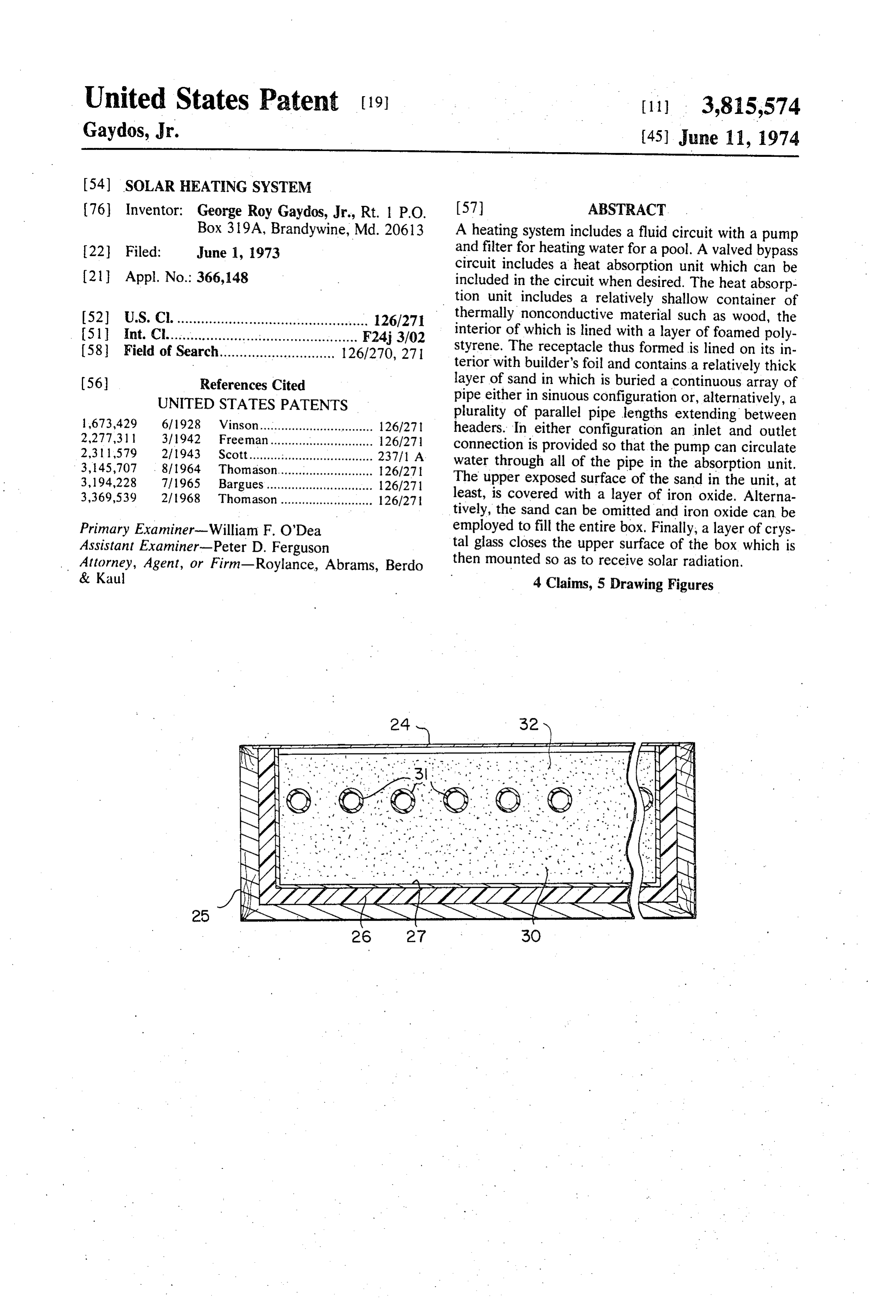
(76) Inventor: George Roy Gaydos, Jr., Rt. 1 P.O. (57) ABSTRACT Box 319A, Brandywine, Md. 20613 A heating system includes a fluid circuit with a pump 22 Filed: June 1, 1973 and filter for heating water for a pool. A valved bypass circuit includes a heat absorption unit which can be 21 Appl. No.: 366,148 included in the circuit when desired. The heat absorp tion unit includes a relatively shallow container of 52 U.S. Cl................................................. 126/271 thermally nonconductive material such as wood, the (51 int. Cl................................................ F243/02 interior of which is lined with a layer of foamed poly 58 Field of Search............................. 126/270, 271 styrene. The receptacle thus formed is lined on its in terior with builder's foil and contains a relatively thick (56) References Cited layer of sand in which is buried a continuous array of UNITED STATES PATENTS pipe either in sinuous configuration or, alternatively, a plurality of parallel pipe lengths extending between 1673,429 6/1928 Vinson................................ 126/27 headers. In either configuration an inlet and outlet 2,277,311 3/1942 Freeman............................. 126/27 connection is provided so that the pump can circulate 2.3 l 1579 2/1943 Scott................................... 237/1 A water through all of the pipe in the absorption unit. 3, 45,707 - 8/1964. Thomason........................... 126/27 3,194,228 7/1965 Bargues.............................. 126/271 The upper exposed surface of the sand in the unit, at 3,369,539 21968 Thomason.......................... 126/27 least, is covered with a layer of iron oxide. Alterna tively, the sand can be omitted and iron oxide can be
Primary Examiner-William F. O'Dea employed to fill the entire box. Finally, a layer of crys Assistant Examiner-Peter D. Ferguson tal glass closes the upper surface of the box which is Attorney, Agent, or Firm-Roylance, Abrams, Berdo then mounted so as to receive solar radiation. & Kaul 4 Claims, 5 Drawing Figures
sT EYA 2 as 3.
SAS
Page 2
Drawing sheet — no readable text.
Page 3
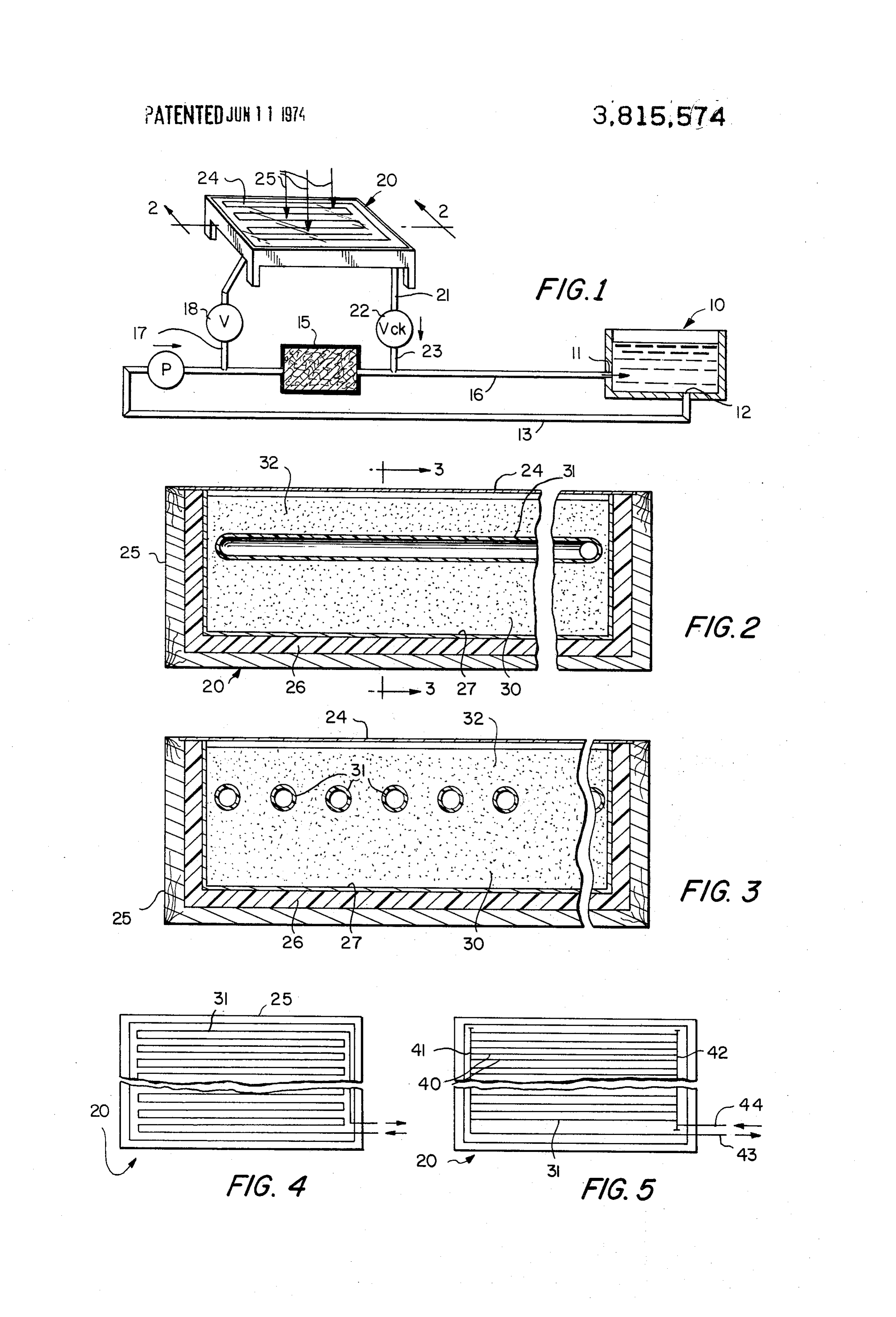
SOLAR HEATING SYSTEM FIG. 5 is a foreshortened plan view of a heat absorp tion unit having a header type array.
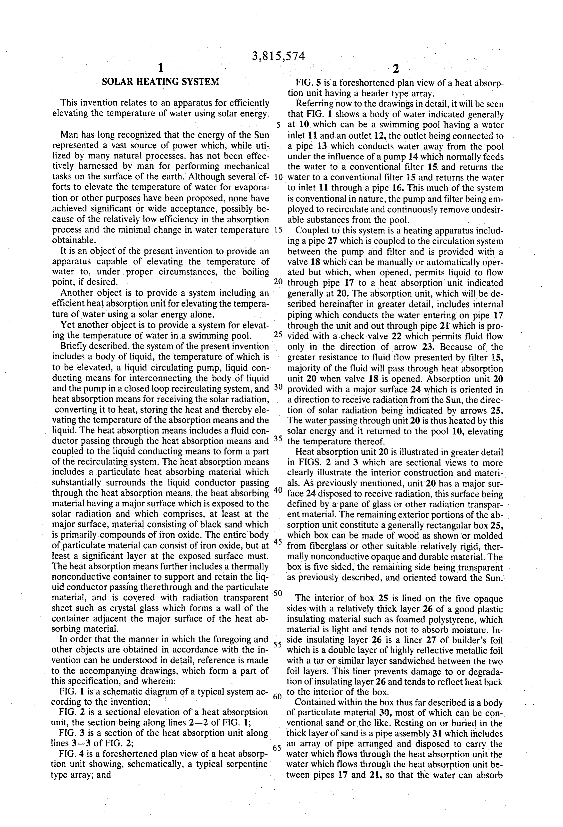
This invention relates to an apparatus for efficiently Referring now to the drawings in detail, it will be seen elevating the temperature of water using solar energy. that FIG. 1 shows a body of water indicated generally at 10 which can be a swimming pool having a water
Man has long recognized that the energy of the Sun inlet 11 and an outlet 12, the outlet being connected to represented a vast source of power which, while uti a pipe 13 which conducts water away from the pool lized by many natural processes, has not been effec under the influence of a pump 14 which normally feeds tively harnessed by man for performing mechanical the water to a conventional filter 15 and returns the tasks on the surface of the earth. Although several ef O water to a conventional filter 15 and returns the water forts to elevate the temperature of water for evapora to inlet 11 through a pipe 16. This much of the system tion or other purposes have been proposed, none have is conventional in nature, the pump and filter being em achieved significant or wide acceptance, possibly be ployed to recirculate and continuously remove undesir cause of the relatively low efficiency in the absorption able substances from the pool. . ... process and the minimal change in water temperature 5 Coupled to this system is a heating apparatus includ obtainable. ing a pipe 27 which is coupled to the circulation system It is an object of the present invention to provide an between the pump and filter and is provided with a apparatus capable of elevating the temperature of valve 18 which can be manually or automatically oper water to, under proper circumstances, the boiling 20 ated but which, when opened, permits liquid to flow point, if desired. through pipe 17 to a heat absorption unit indicated Another object is to provide a system including an generally at 20. The absorption unit, which will be de efficient heat absorption unit for elevating the tempera scribed hereinafter in greater detail, includes internal ture of water using a solar energy alone. piping which conducts the water entering on pipe 17 Yet another object is to provide a system for elevat through the unit and out through pipe 21 which is pro ing the temperature of water in a swimming pool. 25 vided with a check valve 22 which permits fluid flow Briefly described, the system of the present invention only in the direction of arrow 23. Because of the includes a body of liquid, the temperature of which is greater resistance to fluid flow presented by filter 15, to be elevated, a liquid circulating pump, liquid con majority of the fluid will pass through heat absorption ducting means for interconnecting the body of liquid unit 20 when valve 18 is opened. Absorption unit 20 and the pump in a closed loop recirculating system, and 30 provided with a major surface 24 which is oriented in heat absorption means for receiving the solar radiation, a direction to receive radiation from the Sun, the direc converting it to heat, storing the heat and thereby ele tion of solar radiation being indicated by arrows 25, vating the temperature of the absorption means and the The water passing through unit 20 is thus heated by this liquid. The heat absorption means includes a fluid con solar energy and it returned to the pool 10, elevating ductor passing through the heat absorption means and 35 the temperature thereof.
coupled to the liquid conducting means to form a part Heat absorption unit 20 is illustrated in greater detail of the recirculating system. The heat absorption means in FIGS. 2 and 3 which are sectional views to more includes a particulate heat absorbing material which clearly illustrate the interior construction and materi substantially surrounds the liquid conductor passing 40 als. As previously mentioned, unit 20 has a major sur through the heat absorption means, the heat absorbing face 24 disposed to receive radiation, this surface being material having a major surface which is exposed to the defined by a pane of glass or other radiation transpar solar radiation and which comprises, at least at the ent material. The remaining exterior portions of the ab major surface, material consisting of black sand which sorption unit constitute a generally rectangular box 25, is primarily compounds of iron oxide. The entire body 45 which box can be made of wood as shown or molded of particulate material can consist of iron oxide, but at from fiberglass or other suitable relatively rigid, ther least a significant layer at the exposed surface must. mally nonconductive opaque and durable material. The The heat absorption means further includes athermally box is five sided, the remaining side being transparent nonconductive container to support and retain the liq as previously described, and oriented toward the Sun. uid conductor passing therethrough and the particulate material, and is covered with radiation transparent 50 The interior of box 25 is lined on the five opaque sheet such as crystal glass which forms a wall of the sides with a relatively thick layer 26 of a good plastic container adjacent the major surface of the heat ab insulating material such as foamed polystyrene, which sorbing material. material is light and tends not to absorb moisture. In In order that the manner in which the foregoing and 55 side insulating layer 26 is a liner 27 of builder's foil . other objects are obtained in accordance with the in which is a double layer of highly reflective metallic foil vention can be understood in detail, reference is made with a tar or similar layer sandwiched between the two to the accompanying drawings, which form a part of foil layers. This liner prevents damage to or degrada this specification, and wherein: tion of insulating layer 26 and tends to reflect heat back FIG. 1 is a schematic diagram of a typical system ac 60 to the interior of the box.
cording to the invention; Contained within the box thus far described is a body FIG. 2 is a sectional elevation of a heat absorptsion of particulate material 30, most of which can be con unit, the section being along lines 2-2 of FIG. 1; ventional sand or the like. Resting on or buried in the FIG. 3 is a section of the heat absorption unit along thick layer of sand is a pipe assembly 31 which includes lines 3-3 of FIG. 2; 65 an array of pipe arranged and disposed to carry the FIG. 4 is a foreshortened plan view of a heat absorp water which flows through the heat absorption unit the tion unit showing, schematically, a typical serpentine water which flows through the heat absorption unit be type array; and tween pipes 17 and 21, so that the water can absorb
Page 4
heat while passing therethrough. Pipe 31 can be a con appropriate diameter. The pipes are connected to each tinuous length of pipe arranged in a serpentine fashion other with a conventional adhesive, commonly used in or it can constitute a plurality of parallel pieces of pipe the assembly of ABS pipe. A second header 42 is con connected at their ends to header members, as will be nected to pipes 40 at their opposite ends. Inlet and out further described. The pipe can be constructed of cop 5 let pipes 43 and 44 are connected to headers 41 and 42, per, but it has been found that the pipe need not be respectively. The assembly can then be placed in the highly thermally conductive material and, in fact, can preassembled structure and covered with the iron oxide be plastic pipe, such as commonly used ABS or acrylo material.
nitrile butadiene styrene pipe which is less expensive While certain advantageous embodiments have been and relatively simple to work. A typical structure in 10 chosen to illustrate the invention it will be understood cludes 25 lengths, or 122 loops, of 34 inch ABS pipe, by those skilled in the art that various changes and spaced on 32 inch centers, in a box which is approxi modifications can be made therein without departing mately 4 feet by 8 feet in outer dimensions and approxi from the scope of the invention as defined in the ap mately 6 inches deep. The pipe is covered by about 2 pended claims.
inches of particulate material. The glass pane 24 is 7/16 5 I claim:
inch flat crystal glass. 1. A solar heating system comprising Of particular consequence in the assembly of this a body of liquid to be heated, structure is the incorporation of a substantial layer 32 a liquid circulating pump;
of "black sand' or magnetite. For reasons for which liquid conducting means for interconnecting said are not completely understood, the incorporation of a 20 body of liquid and said pump in a closed loop recir ferric compound and, specifically, this iron oxide com culating system; and pound as the upper layer of the material beneath the heat absorption means for receiving solar radiation glass in the box vastly improves the heat absorption and for converting to and storing heat from said ra characteristics thereof and permits maximum utiliza diation and for transferring the heat to the liquid, tion of that solar energy which falls upon pane 24. In 25 said heat absorption means comprising fact, material 30 and 32 can all be iron oxide with no pipe means coupled to said liquid conducting added sand, but it is particularly significant that the top means to form a part of said recirculating system; one fourth inch of the portion between pipe 31 and window 24 be iron oxide for best effect. a particulate heat absorbing material substantially The iron oxide compound which has been utilized 30. surrounding said pipe means and having a major primarily and found to be effective is that colloquially surface exposed to the solar radiation, at least the referred to as "black sand" and constitutes part of the major surface of the material consisting of iron. tailings remaining after a gold placer mining, or gold oxide, panning, operation. The material is not truly sand in the a thermally nonconductive container to support sense of being silica compound but, instead, is an iron 35 and retain said pipe means and said material; and oxide which is largely magnetite (FeO4) with titanium compounds such as ilmenite (FTO) or rutile (TO) a radiation transparent sheet forming one wall of and other iron compounds, and is a naturally occurring said container adjacent said major surface of said material in for example, the geologic formations in heat absorbing material. which gold is found. The residue from the placer min 40 means 2. A system according to claim 1 wherein said pipe ing operations has been employed, and has been found includes to give excellent results, in a structure as above a plurality of substantially parallel pipe sections and described. first and second transverse header pipes, each of Further discussions of the black sand, as this term is said header pipes being connected to one end of used herein, can be found in Bureau of Mines Informa 45 each of said pipe sections; and tion Circulars 8517 and 7000. first and second coupler pipes for connecting said As previously mentioned, the pipe in the box can be first and second headers, respectively, to said liquid arranged in either of at least two ways, these being conducting means.
schematically illustrated in FIGS. 4 and 5. In FIG. 4, 3. A system according to claim 1 wherein said pipe the pipe is arranged in a serpentine fashion with the 50 means comprises pipe being continuously wound back and forth in the a pipe formed in a serpentine array lying substantially box alternatively, it is possible to employ the header ap in a single plane.
proach wherein a plurality of parallel lengths of plastic 4. A system according to claim 1 wherein a majority pipe 40 are connected at one end to a header 41 which 55 of said particulate material is magnetite. is provided with a plurality of equally spaced holes of :k sk sk sk xk
Provenance
- Collection
- Cited prior art
- Original PDF
- patentimages.storage.googleapis.com →
- Filed
- 1973-06-01
- Pages
- 4
- Method
- pdftotext (the PDF's own text layer) + pdftoppm 300dpi page scans
- Source
- Google Patents bibliographic record
- Granted
- 1974-06-11
- Inventors
- G Gaydos
- Transcribed from
- patentimages.storage.googleapis.com →