patent · US4233127
Process and apparatus for generating hydrogen and oxygen using solar energy
11 November 1980
Page 1 — bibliographic record
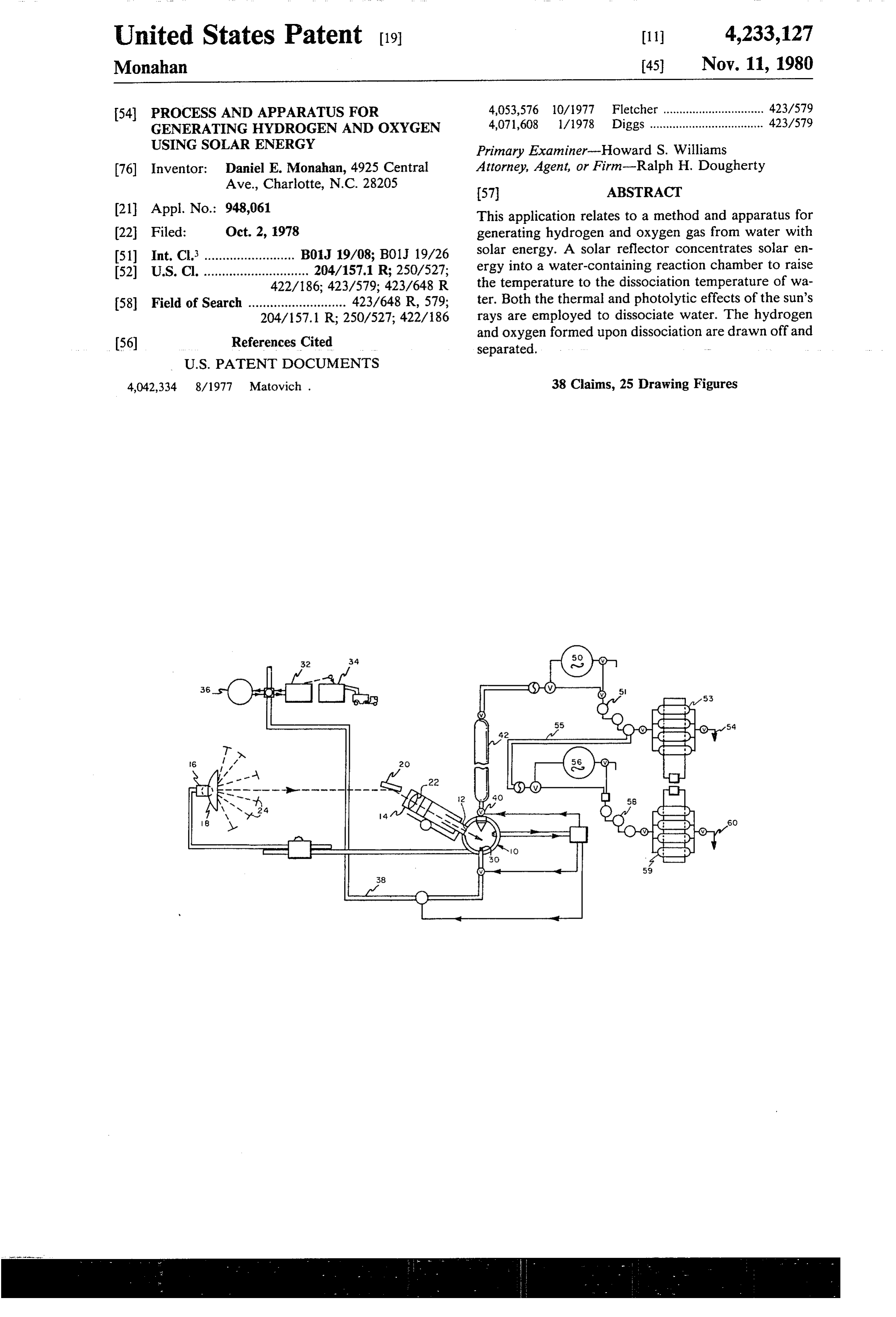
United States Patent (19) 11 4,233,127 Monahan (45) Nov. 11, 1980 54 PROCESS AND APPARATUS FOR 4,053,576 10/1977 Fletcher ............................... 423/579 GENERATING HYDROGEN AND OXYGEN 4,071,608 1/1978 Diggs ................................... 423/579 USING SOLAR ENERGY Primary Examiner-Howard S. Williams (76) Inventor: Daniel E. Monahan, 4925 Central Attorney, Agent, or Firm-Ralph H. Dougherty Ave., Charlotte, N.C. 28205 (57) ABSTRACT 21 Appl. No.: 948,061 This application relates to a method and apparatus for (22 Filed: Oct. 2, 1978 generating hydrogen and oxygen gas from water with (51) Int. Cl. ......................... B01J 19/08; B01J 19/26 solar energy. A solar reflector concentrates solar en (52) U.S. Cl. ............................. 204/157.1 R; 250/527; ergy into a water-containing reaction chamber to raise 422/186; 423/579; 423/648 R the temperature to the dissociation temperature of wa 58 Field of Search ........................... 423/648 R, 579; ter. Both the thermal and photolytic effects of the sun's 204/157.1 R; 250/527; 422/186 rays are employed to dissociate water. The hydrogen and oxygen formed upon dissociation are drawn off and (56) References Cited - separated.
4,042,334 8/1977 Matovich . 38 Claims, 25 Drawing Figures
Page 2
Drawing sheet — no readable text.
Page 3
Drawing sheet — no readable text.
Page 4
Drawing sheet — no readable text.
Page 5
Drawing sheet — no readable text.
Page 6
Drawing sheet — no readable text.
Page 7
Drawing sheet — no readable text.
Page 8
Drawing sheet — no readable text.
Page 9
Drawing sheet — no readable text.
Page 10
near ultra-violet wave lengths (approximately 102 to
PROCESS AND APPARATUS FOR GENERATING 10° angstroms) of the light spectrum directly excite the HYDROGEN AND OXYGEN USING SOLAR vibrational level of the molecular bonds beyond the ENERGY level required for fracturing of the molecular bonds
BACKGROUND OF THE INVENTION
resulting in the dissociation of the water molecules into atoms molecules and ions of hydrogen (H+, H2) and
This invention relates to the generation of hydrogen oxygen (O, O2), and hydroxyl radicals (OH). Thus, the and oxygen from water using solar energy. According near ultra-violet wave frequencies of the natural light to the present invention, solar energy is converted into spectrum can supply additional energy for breaking the potential energy in the form of hydrogen and oxygen O molecular bonds in water vapor. Therefore, concen which may be in liquid or gaseous state, or as solid trated ultra violet energy in combination with high compound such as a metallic hydride. The uses of liquid levels of thermal energy can allow a given rate of direct oxygen are well known. Since demands on conven dissociation of the molecules of water vapor to take tional non-replaceable fossil fuels have increased drasti place at lower thermal energy levels and with greater cally over the recent decade, threatening the world 15 energy supply of these natural resources and the cost of genera alone is utilization efficiencies than if thermal energy employed. Conversely, at a given level of ther tion of electric and nuclear power have both increased mal energy, drastically, it has become clear that a new fuel is proceed at adissociation of water vapor molecules will needed. Hydrogen is readily available in water and fills 20 The presentgreater rate.
invention takes full advantage of both the this need. There are presently available engines and heating and power plants which can run on hydrogen. thermal and photolytic properties of solar energy (sun In prior art devices such as that taught in U.S. Pat. light).
No. 4,030,890, solar energy (sunlight) is converted into Thus, this invention has significant advantages over thermal energy (heat) through mechanical means and 25 other solar energy devices.
with attendant energy losses. This thermal energy is Direct dissociation of water molecules in my inven then transferred, with additional energy losses, through tion can take place at lower thermal energy levels and metallic interfaces to the reactant (water) until sufficient with greater energy utilization, thus smaller scale col thermal energy has been transferred to the water to lection apparatus can be employed with equivalent bring about its thermal decomposition. Such devices results, with an attendant lower capital investment. have several major disadvantages. They rely solely on 30 Since prior art devices transmit thermal energy to the thermal energy to promote dissociation. Thus, they do water indirectly through the wall of a metallic con not take advantage of the ability of certain frequencies tainer, there are substantial energy losses due to the of the light spectrum, primarily the near ultraviolet conduction transfer through the container. wave ranges to fracture the molecular bonds in the The concentrated solar energy initially impacts the molecules of water vapor, causing direct dissociation 35 through the medium of wave form irradiation. This container wall of previously known devices directly at phenomenon is known as photolysis, or the photolytic the extremely high temperature levels required to (a) effect of the ultraviolet radiation in sunlight upon the overcome energy transfer losses and (b) sustain the molecular bonds in water vapor molecules. When com extremely high internal temperatures required for direct bined with the known effects of high thermal energy thermal dissociation. This requires that the container be levels upon water vapor molecules to cause direct ther constructed of materials capable of withstanding these mal decomposition of the water into elemental and extremely high temperature concentrations and the molecular hydrogen and oxygen, the photolytic effect rapid upward and downward temperature excursions permits a given rate of decomposition to take place at caused by abrupt fluctuations in the level of available lower temperatures, and with greater efficiency of en 45 sunlight over extended periods without undergoing ergy utilization than if thermal energy alone is em catastrophic failure e.g. by fusion, thermal shock, frac ployed. The combined effects of high thermal energy ture, corrosion, embrittlement, etc. Suitable materials and photolytic effect of ultraviolet radiation allow dis such as tungsten not only are very expensive, but also sociation of water vapor to take place at a greater rate are very difficult to machine and manufacture. than if thermal energy alone is employed. 50
The method of the present invention causes the con
The mechanism through which this combined reac centrated solar energy to interact directly with the tion takes place is believed to be as follows:
First, a portion of the concentrated incoming radiant water contact vapor in the reaction chamber, avoiding direct of the concentrated light beam with any portion energy (sunlight) primarily the infra-red frequencies of the reaction (wave-lengths of approximately 10 to 106 angstroms) is 55 pensive materialschamber can be structure. Therefore, less ex used to contain the reaction.
converted to thermal energy (heat) upon contact with water vapor. This thermal energy is then absorbed by OBJECTS OF THE INVENTION the molecules of the water vapor, agitating (heating) the Accordingly, it is the principal object of this inven water molecules and gradually increasing the frequency level of molecular vibrations to the level required for 60 tion to provide a means for obtaining hydrogen at low rupture of the molecular bonds and dissociation of the cost using solar energy.
It is another object to provide a means for obtaining water molecules into their components. It is known that elemental the level of thermal energy required for this molecular oxygen as a byproduct from the process. dissociation is extremely high, in excess of 3000 K. at It is a further object to provide a method and appara standard pressure. 65 tus for generating hydrogen and oxygen using solar Second, radiant wave form energy in the form of energy.
concentrated sunlight, directly bombards the agitated It is also an object to reduce the likelihood of failure molecular bonds of the water vapor molecules and the of materials of construction due to heat.
Page 11
ployed to direct the sun's rays into reflector 18 and
SUMMARY OF THE INVENTION increase the intensity of the rays of solar energy col This invention utilizes solar energy by concentrating lected. Water is injected into the bottom of reaction solar rays into a water-containing reaction chamber, chamber 10 through an injector head 30. The water is raising the temperature within the reaction chamber to preferably demineralized by ion exchange in a standard at least as high as the dissociation temperature of water, demineralizing apparatus 32, and the minerals are re dissociating the water by a combination of thermal covered at 34 as an additional byproduct of this process. energy and photolysis, withdrawing the dissociated Cleaned, demineralized (chlorine-free) water is stored gases, hydrogen and oxygen, into a gas separating in holding tanks 36 until pumped through line 38 to the means, separating the two gases, and processing them 10 water injector head 30. The temperature in the reaction for later use. Alternatively, separation may be achieved vessel 10 is raised to at least 4500 F. by directing con in the reaction chamber. centrated solar energy therein. The optimum dissocia BRIEF DESCRIPTION OF THE DRAWINGS tion temperature of water is in the range of 5000 to 7500 F. However, the dissociation reaction begins at a
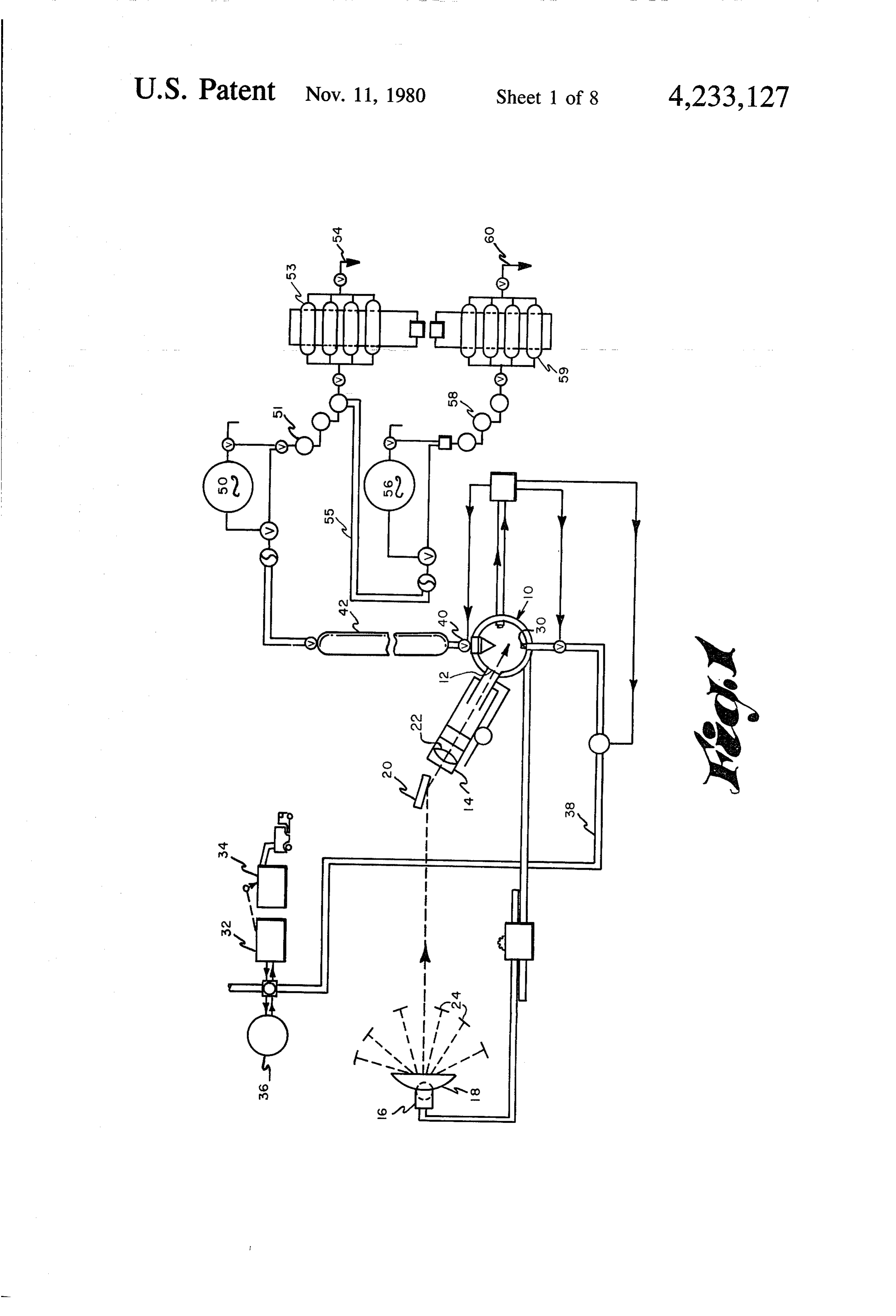
This invention is better understood by referrng to the 15 temperature of about 4500 F.
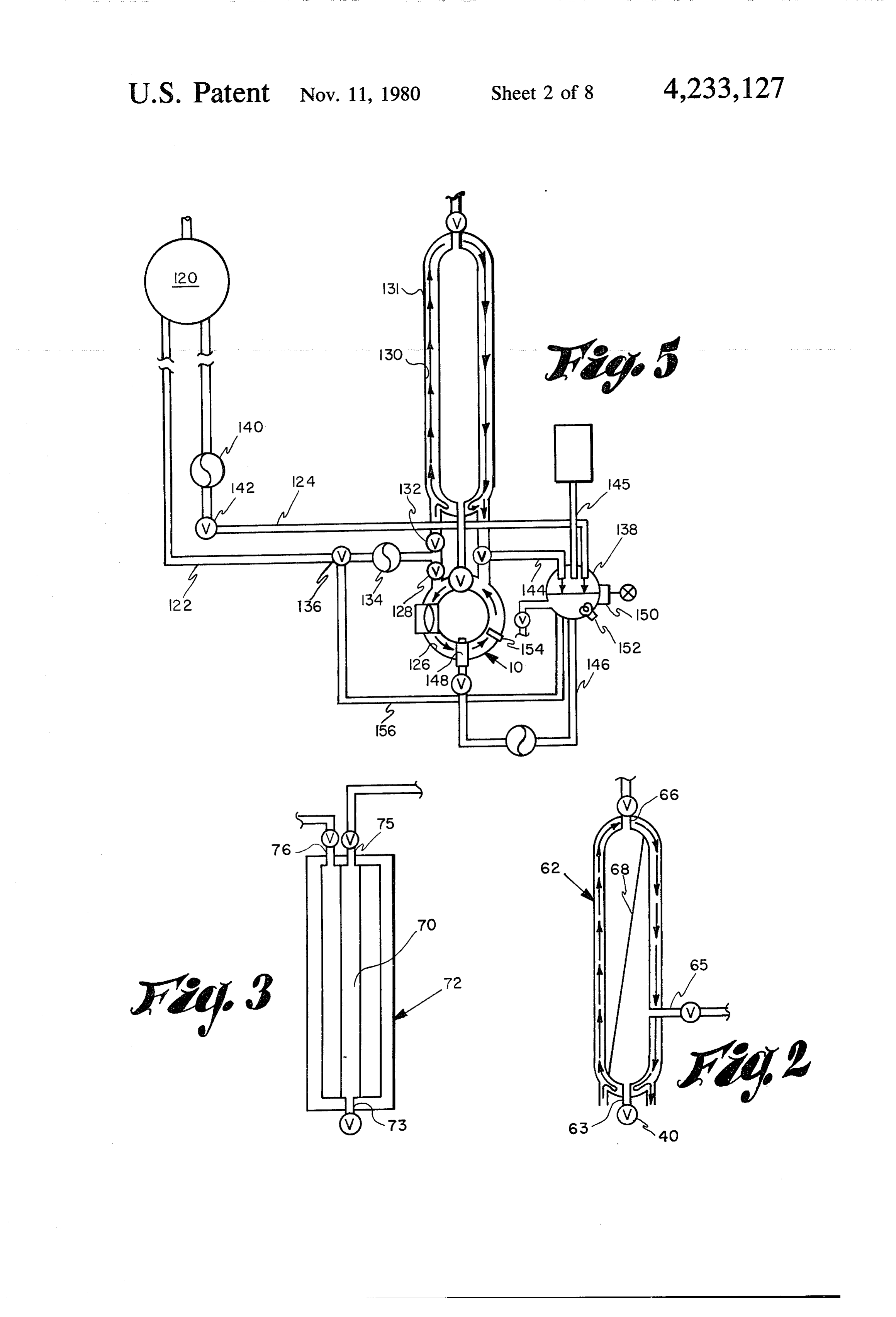
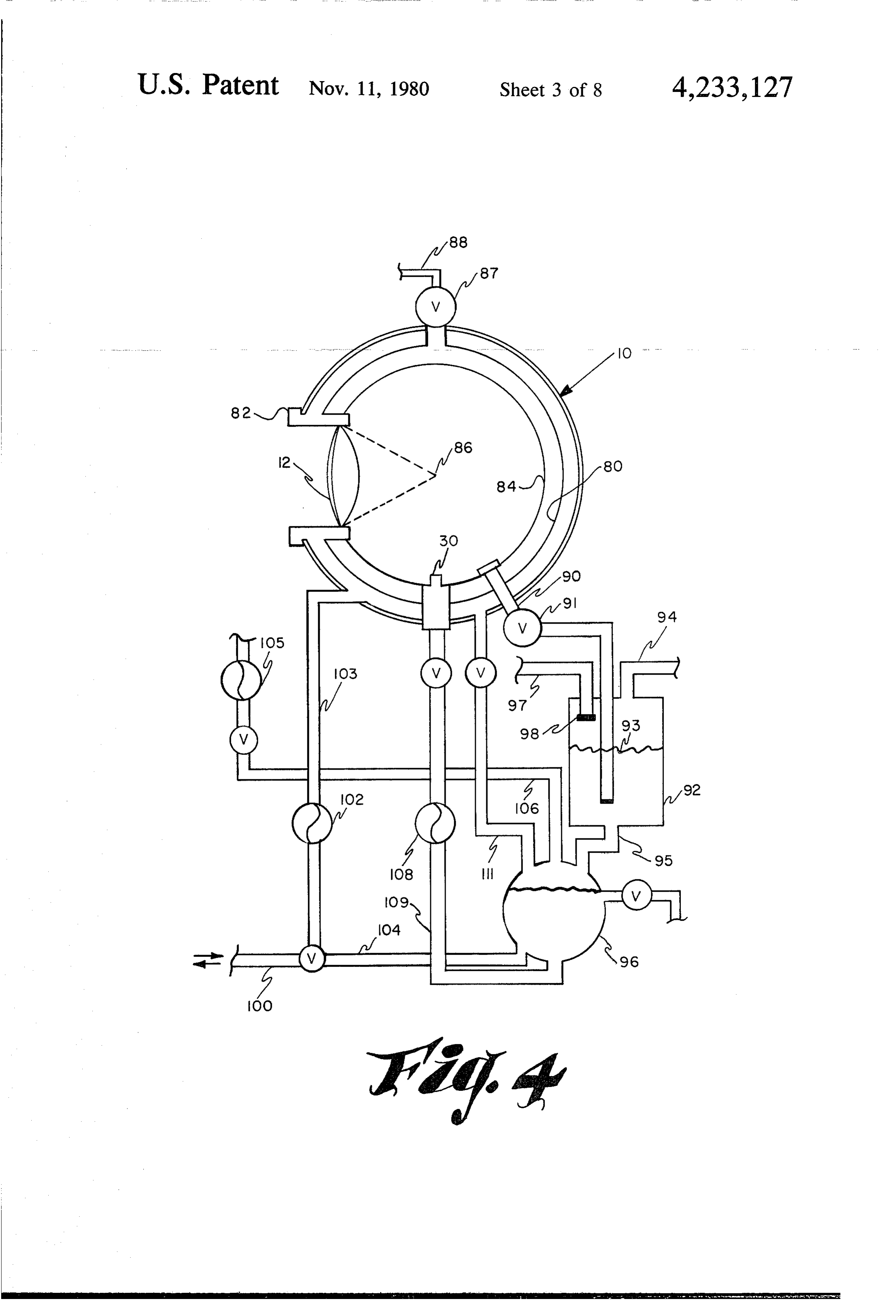
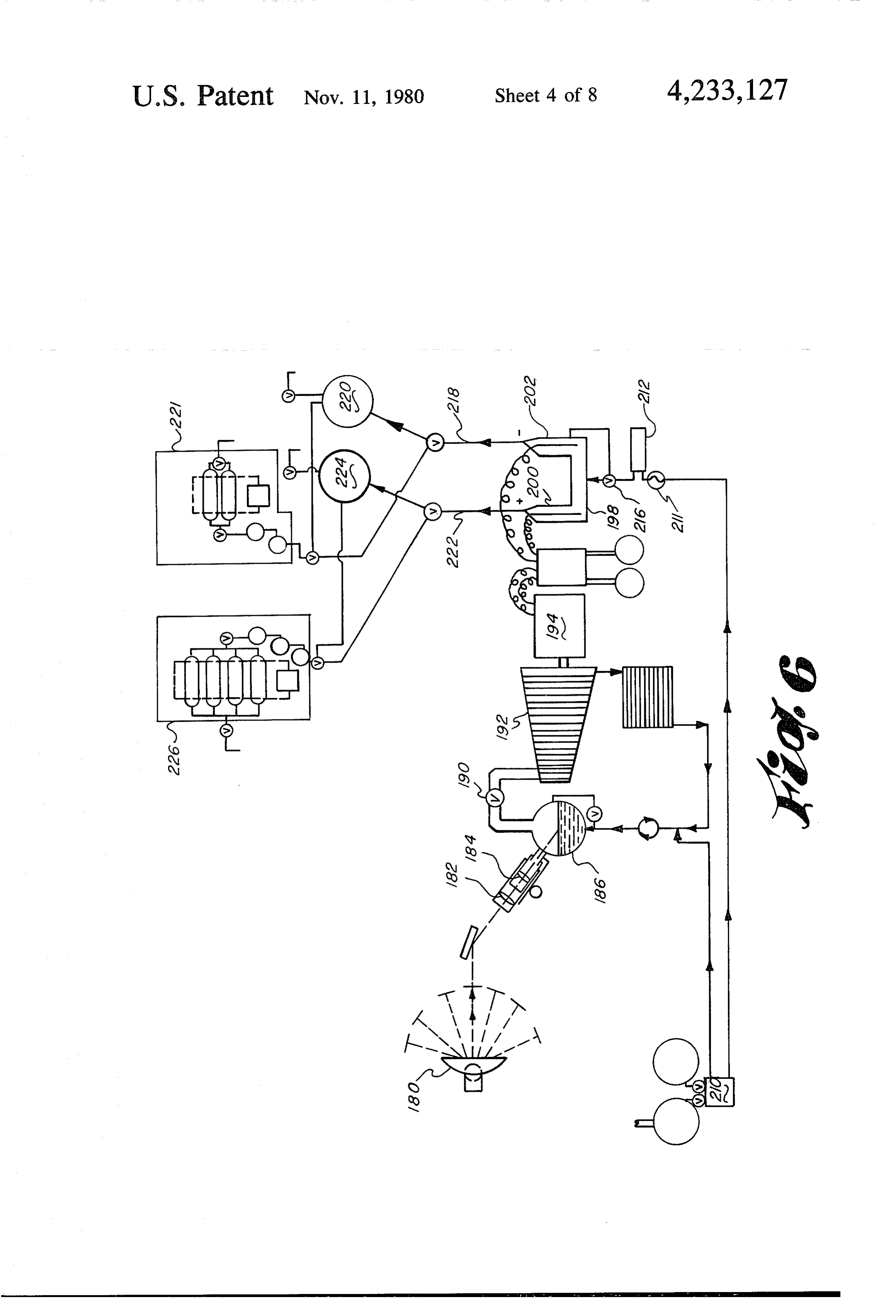
following detailed specification and the appended The dissociated hydrogen and oxygen and other by drawings in which: products in the gaseous state are released from the reac - FIG. 1 illustrates schematically one embodiment of tion chamber through a servo pressure valve 40 into a this invention. gas collecting tank 42 which is associated with a gas FIG. 2 is a cross-section of a gas separation tank 20 separating means such as a separator tank or a perme having a specific gas permeable membrane separation able membrane separating unit. The mixed dissociated 88S. gases may be separated by one of several techniques FIG. 3 is a cross-section of an alternative gas separa such as compression or refrigeration in series connected tion tank. compressors or refrigeration units 51 and the resulting FIG. 4 illustrates schematically a reactor vessel in 25 liquid oxygen is stored in tanks 53 such as Dewar flasks, cluding an internal oxygen-hydrogen separation system the low temperature of which is maintained by a com and associated process water piping. pression-liquefaction and repressurization system. FIG. 5 illustrates schematically a coolant-preheater The remaining unseparated gas is circulated through loop suitable for operation in the invented method. line 55 from where it may be stored in tank 56 for future FIG. 6 illustrates schematically an alternative em 30 use, or it may be refrigerated and compressed in units 58 bodiment of this invention. to liquid hydrogen and stored in tanks 59 such as Dewar FIG. 7 is a schematic illustration of apparatus for flasks from which liquid hydrogen may later be with forming a granular metal hydride. drawn at 60.
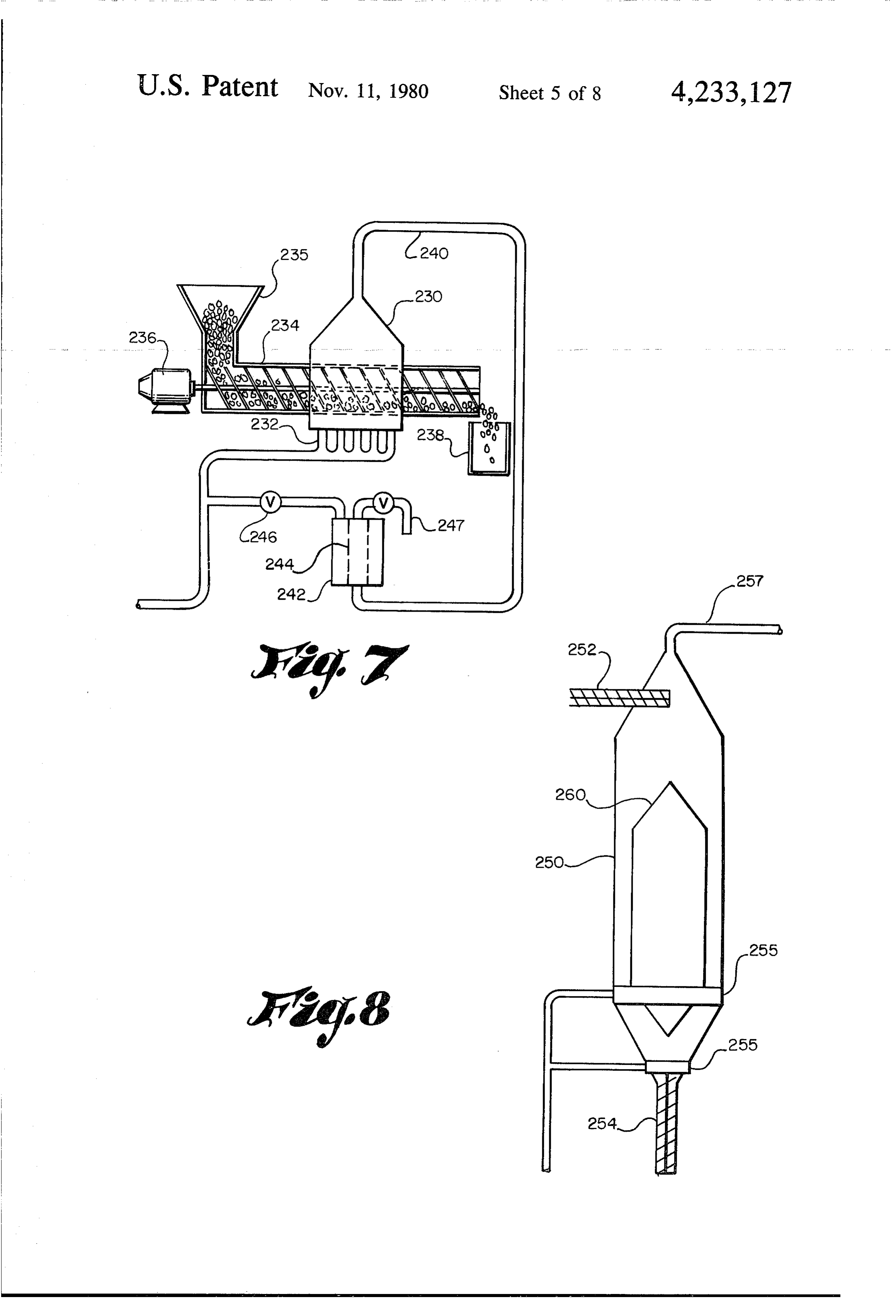
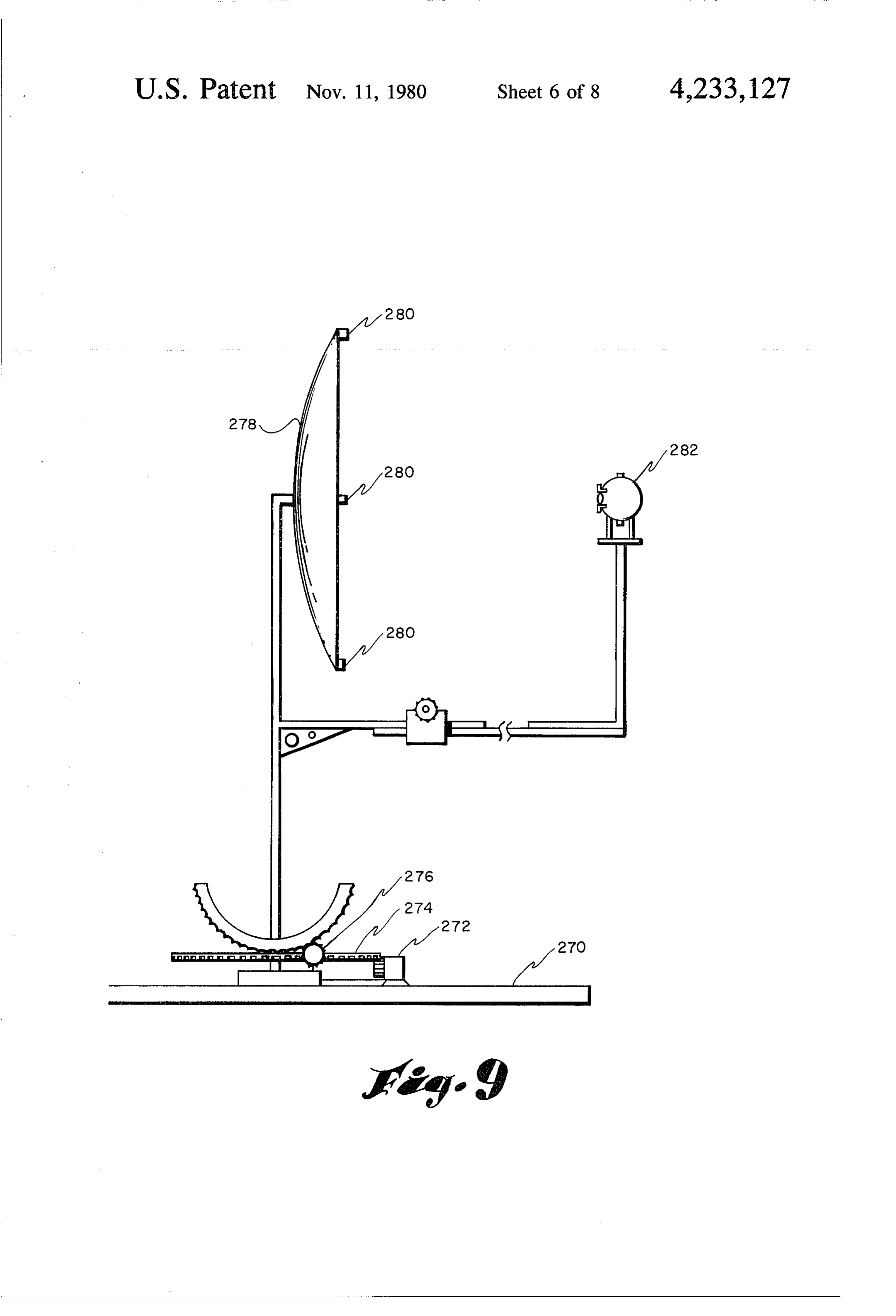
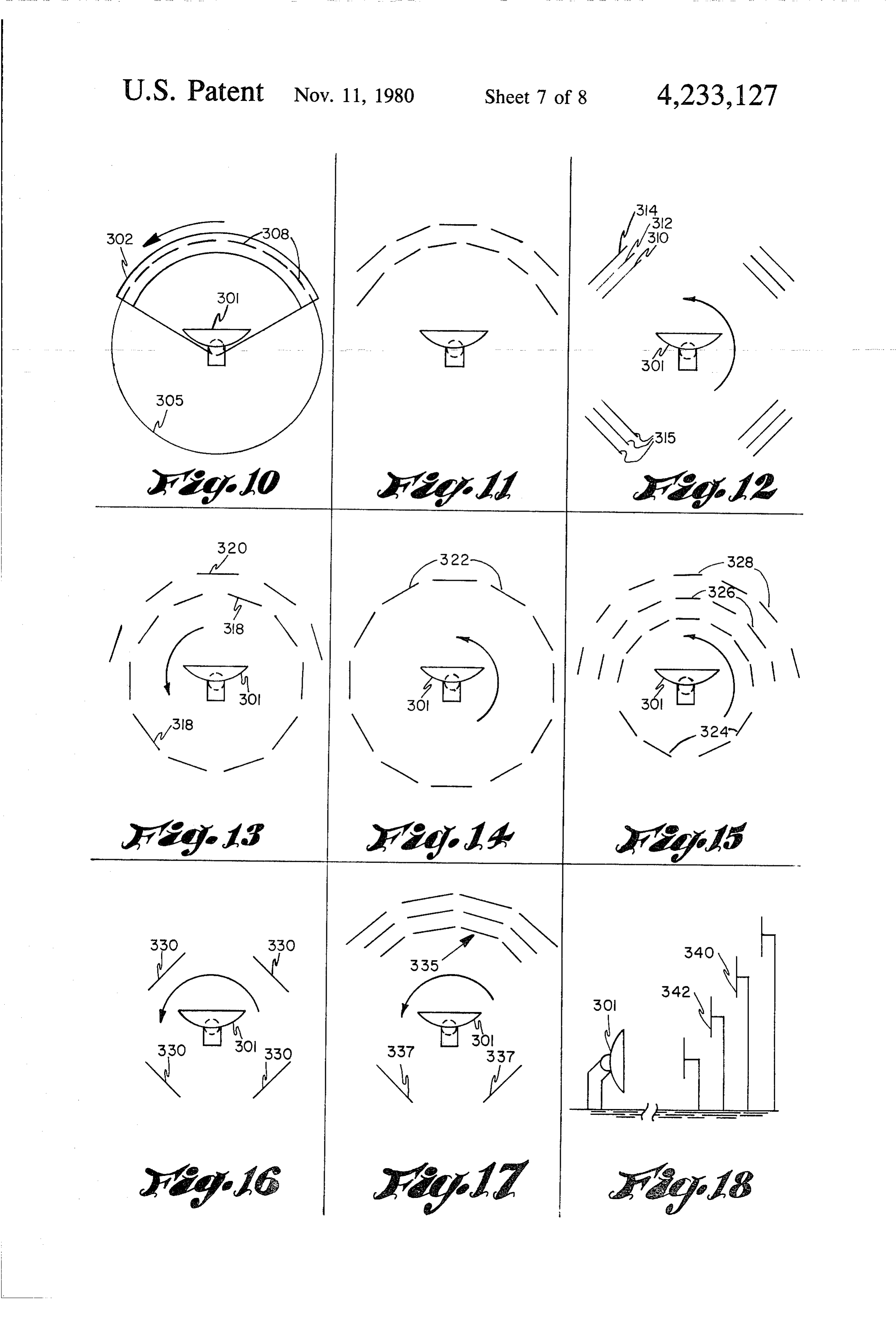
FIG. 8 is a schematic illustration of alternative appa A preferred method of separating hydrogen from the ratus for forming a granular metal hydride. 35 reaction products is by diffusion through a hydrogen FIG. 9 is a side elevational view of a tracking reflec permeable membrane or molecular sieve such as silver tor showing the relative location of a reaction chamber palladium, or a finely woven mesh membrane of irid and associated drive mechanisms. ium, thoria, or other heat-resistant refractory oxide. FIGS. 10 through 17 are plan views of various ar FIG. 2 shows a permeable membrane apparatus for rangements of solar energy collectors wherein helio separating the reaction products. Tank 62, which would stats are arranged about a parabolic reflector. be positioned in FIG. 1 in the location of tank 42, has an FIG. 18 is a side elevational view of a heliostatar inlet pipe 63 leading from valve 40, an oxygen outlet rangement for directing solar energy into a parabolic pipe 65 and a hydrogen outlet pipe 66. A hydrogen reflector. permeable membrane 68 separates the tank into two FIGS. 19 through 22 are cut-away side views of a 45 compartments. The membrane 68 can be angled as reaction chamber with spray ring injector heads situ shown in FIG. 2 or can be inserted at any other desired ated therein. angle, including horizontal. Alternatively, the hydro FIG. 23 is a sectional view of the reaction chamber . gen permeable membrane can be in the form of a tube 70 and spray ring taken along line A-A of FIG. 22. as shown in FIG. 3. In this case, tank 72 has an inlet 73 FIG. 24 is a schematic cut-away view of a tubular 50 an oxygen outlet 75 and a hydrogen outlet 76. The tanks reaction chamber utilizing spray ring injectors. 62 or 72 should be water jacketed as shown. Note that FIG. 25 is a tubular reaction chamber similar to that the hydrogen is the only product that will pass through of FIG. 24 utilizing an alternative spray injector spray the membrane, thus other impurities such as water apparatus. vapor will be taken off with the oxygen.
DETAILED DESCRIPTION
55 Another suitable separation method is the gravity density technique by which the differential in atomic
Referring now to FIG. 1, a reaction chamber 10 is a weights or densities of hydrogen and oxygen is utilized sealed vessel lined with high temperature ceramic and to move the elements away from each other by the /or reflective material. Mounted in the wall of the reac force of gravity in a vertical tank, resulting in oxygen tion chamber is a transparent focusing lens 12 which 60 being drawn off at the bottom and hydrogen being also acts as a vapor barrier. A movable focusing lens drawn off at the top. A third separation technique is tube 14 external to the chamber is directed toward the compression-liquefaction, in which a mixture of the lens 12. An automatic tracking drive mechanism 16 is dissociated gases is compressed. Gases are then passed connected to a 2-axis 360 tracking parabolic reflector through a porous plug or Joule-Thomson valve and the 18, which collects the sun's rays and reflects them 65 constituent gases are separated in a reverse distillation against an optional mirror 20, which directs the rays process as cryogenic liquids. Other alternatives separa through optional collector lens 22 and focusing lens 12. tion techniques that may be employed include; diffusion Secondary reflector such as heliostats 24, may be em through an oxygen-permeable membrane, magnetic
Page 12
separation, ionic charge separation through mass spec condensate from other parts of the process through troscopy, hydrogen absorption, oxygen absorption, and condensate return line 145. The mixing tank has an solubility separation. outlet line 146 at its lower portion which is connected to The separation of hydrogen and oxygen should take injector head 148 of the reaction chamber. A water place as close to the reaction zone as possible. After the level sensor 150 in the mixing tank controls the input of gases have left the reaction zone, the temperature be water to the mixing tank through valve 142. Thermo gins to drop and recombination takes place rapidly. couple 152 monitors the water temperature in the mix FIG. 4 shows a reaction chamber configuration and ing tank and thermocouple 154 monitors the coolant associated apparatus for achieving hydrogen and oxy temperature being circulated in the cooling jacket of the gen separation within the reaction chamber itself. This O reaction chamber. Between periods of operation, water allows the separation of hydrogen and oxygen to take from tank 138 is recirculated through line 156 and valve place at the highest possible temperature which results 136 into the cooling jackets to remove excess latent heat in greater yields and higher efficiencies than when sepa to prevent thermal destruction of the major compo ration is carried out at lower temperatures and at more nents.
remote locations. 15 The water in the cooling jackets 126 and 130 absorbs In FIG. 4, reactor 10 has a water cooled jacket 80 and surplus heat from the reaction and separation chambers carries lens 12 in a water-cooled lens sleeve 82. A hy which was not used by the dissociation reaction as well drogen-permeable membrane 84 which has the same as heat that is rejected as energy of recombination when general configuration as reactor 10 is situated within the atoms of the dissociated bases recombine to form mole reactor. A variable spray injector head 30 provides the 20 cules of gases and water vapor. The preheated water is water source for the reactor. Lens 12 focuses at a point then circulated into the preheater mixing tank 138 86 within the reactor above the spray head. Concentra where it becomes mixed with other incoming process tion of solar rays at point 86 dissociates water into ele water at ambient temperature, thus preheating all the mental hydrogen, oxygen and other products as men water in the mixing tank to about the same temperature tioned before. Hydrogen, which passes through the 25 prior to its injection through injector head 148 into the membrane 84, is removed from the reactor through reaction chamber. The coolant-preheater loop has sev valve 87 and hydrogen takeoff line 88. Oxygen is re eral distinct advantages. First it removes excess heat moved along with other impurities such as water vapor build-up and rejected energy of recombination from the from the inner chamber of the reactor through oxygen reaction chamber and separation tank, thus reducing the takeoff line 90 and valve 91 to a water containing gas 30 probability of catastrophic failure of these components. separator tank 92. The oxygen and other impurities Second, it uses this otherwise lost energy (waste heat) enter tank 92 beneath the water level 93, are bubbled productively to preheat incoming process water. Third, through the water which will condense the water vapor by preheating the incoming process water prior to in to liquid. Oxygen is then removed through takeoff line jection into the reaction chamber, greater process effi 94. Separator tank water is removed from the separator 35 ciencies are achieved over other systems. Since the tank 92 through a water line 95 to a preheater mixing incoming water temperature does not have to be in tank 96. Makeup cooling water is introduced to gas creased as much, less energy is required to increase the separator tank 92 through waterline 97. Optionally, the temperature of the water vapor reactant to the dissocia makeup water may be injected through a spray head 98. tion point. Because more energy is made available for Cooling water for water jacket 80 and lens sleeve 82 the dissociation process by this method, a greater quan is provided from pipe 100 and pumped through pump tity of water vapor can be dissociated with a given 102 and pipe 103 into jacket 80. Between operating amount of radiant energy, or a given amount of water periods cooling water may be recirculated from tank 96 vapor can be dissociated at a greater rate than in previ through pipe 104. The main process water supply is ously known systems.
provided through pump 105 and line 106 to mixing tank 45 FIG. 6 shows an alternative embodiment of this pro 96 wherein it is preheated. Pump 108 withdraws the cess wherein solar energy is utilized to heat water in a preheated water from tank 96 through line 109 and boiler to a sufficient temperature to operate a steam forces it through injector head 30 into reactor 10. Cool turbine, which in turn runs a generator. The power ing water return line 111 returns cooling water from the generated operates an electrolytic cell in which hydro cooling water jacket 80 to mixing tank 96. 50 gen and oxygen are formed from water. Referring now Depicted in FIG. 5 is a system by which a portion of to FIG. 6, a parabolic reflector 180 directs solar energy the incoming process water may be diverted and circu through a collector lens 182 and a focusing lens 184 into lated though the cooling jacket surrounding the reac a water-containing boiler 186. The temperature in the tion chamber and another portion circulated through boiler is sufficiently high that water entering it will flash the cooling jacket of the separation chamber, thus pre 55 to steam, which will then pass through turbine throttle heating both portions of the incoming process water. valve 190 into steam turbine 192, driving associated Referring now to FIG. 5, demineralized water storage generator 194.
tank 120 feeds water lines 122 and 124. Line 122 is con The electrical output of generator 194 provides the nected to cooling jacket 126 of the reaction chamber electrical input to an electrolytic dissociator 198, having through valve 128. Line 122 is also connected to the 60 a anode 200 and a cathode 202. Fresh demineralized cooling jacket 130 of separation tank 131 through valve water from water supply 210 is fed through pump 211 to 132. Included in the circuit of water line 122 are a pump a mixing station 212 wherein the water is mixed with 134 and a bypass valve 136 which is connected directly dilute solution of H2SO4 or other electrolyte to form an to preheater mixing tank 138. Water line 124 is con electrolyte solution. The electrolyte solution is intro nected directly to preheater mixing tank 138 and is 65 duced to electrolytic dissociator 198, such as a U-tube, provided with a water pump 140 and a control valve the water level of which is kept constant by a level 142 in the line. Also feeding mixing tank 138 are recy control 216. Elemental hydrogen is formed at the cath cled cooling water through line 144 and recirculated ode 202 and is removed through line 218. It may be
Page 13
stored in the gaseous form in pressure vessel 220, or it The tracking mechanism employed includes two may be refrigerated to liquid hydrogen in unit 221. systems. The first system, shown in FIG. 9, is an auto Gaseous oxygen is removed through line 222 from the matic timer controlled tracking mechanism pro anode 220 and it likewise may be stored in gaseous form grammed to follow the path of the sun across the sky. in tank 224, or it may be liquified in refrigeration unit The timer controls a two-axis drive mechanism 226. Alternatively, hydrogen may be combined as a mounted on the base plate 270 of the reflector-dissocia metallic hydride and stored in this form for later use. tor mounting base and synchronizes the direction and Two means for combining hydrogen as a metallic rate of movement of the axis of the parabolic reflector hydride are shown in FIGS. 7 and 8. In each instance, with the center point of the sun's images as it trasverses hydrogen is introduced to the bottom of a reactor 10 its path through the sky each day.
through which a light metal or alloy in granular form is Drive 272 engages horizontal rotation gear 274 for passed. Suitable light metals are those which will tracking the sun from dawn to dusk through an angle of readily form hydride compounds which will release the about 180 degrees. If desired this drive could move the hydrogen when subjected to a relatively small amount mechanism through 360 degrees merely by making gear of heat. Vanadium is a preferable material but magne 15 274 round. Tilting drive mechanism 276 comprises a sium is also suitable as are the following metals and ring and pinion gear or any other suitable drive means alloys which form interstitial hydrides: to tilt the parabolic reflector 278 through any desired Vanadium-columbium, lanthanum-copper-nickel, angle up to approximatey 170 degrees.
zirconium-nickel, titanium-nickel, iron-titanium, titani This automatic timer controller tracking mechanism um-iron-chromium, palladium, titanium-iron-man 20 is similar to those devices used to control the movement ganese, lanthanum-nickel, titanium-copper, titanium of astronomers telescopes in tracking a given star in its manganese, magnesium-nickel, magnesium-copper, sil nightly path through the sky and is programmed daily ver-palladium, platinum-palladium, columbium, cop using known data regarding the sun's path through the per-palladium, and manganese-nickel. sky for each day of the calendar year, from a given As shown in FIG. 7, a reactor 230 has a multiplicity 25 latitude and longitude. This programmable timer con of hydrogen inlet pipes 232 for introducing hydrogen trol unit can be located either on the base of the mount through its bottom wall. A screw feeder 234 is fed by ing mechanism or within the programmable control unit granular light metal from hopper 235 and driven by or both.
associated drive motor 236. The screw feeder is in an The second tracking system includes infra-red and enclosed housing and at its end discharges metal hy 30 ultra-violet sensors 280 mounted at the perimeter of dride material into a storage bin 238. Hydrogen passes each of the four quadrants of the parabolic reflector. through the inlet pipes 232 into reactor 230 then The function of these sensors is to provide input signals through the granular metal in the reactor forming a to the programmable control logic unit to enable the metal hydride. Any unreacted hydrogen is withdrawn computer logic to fine tune or trim the alignment of the through pipe 240 and recycled through chamber 242 35 reflector as it follows the path of the sun across the sky. which has a hydrogen permeable membrane 244. Hy This optimizes the amount of usable sunlight that re drogen passes through membrane 244 and is withdrawn aches the reflector 278 and subsequently the reaction through valve 246 and reintroduced to reactor 230. Any chamber 282. The reflector alignment is automatically impurities remaining in chamber 242 from the removed balanced through servo-drive mechanisms until the hydrogen stream are removed through pipe 247. 40 signals generated by the ultra-violet and infra-red sen An alternative embodiment as shown in FIG. 8 in sors 280 at each of the four points around the rim of cludes a vertically elongated reactor 250 having a feed reflector 278 are equalized and optimized at the level of mechanism 252 for introducing particulate material at greatest available solar energy input to the reflector. its upper end and a discharge mechanism 254 at its The programmable logic for this infra-red tracking lower end for removing reacted particulate material. 45 system has the capacity to override the control of the Also near its lower end are one or more hydrogen injec timer controlled tracking mechanism in circumstances tors 255 for introducing gaseous hydrogen to the inte where a wide divergence exists between the input sig rior of the reactor. A hydrogen takeoff pipe 257 is pro nals of the two systems, e.g. when the sun's rays become vided for removing excess hydrogen and recirculating temporarily obscured by a cloud, or the amount of it to the hydrogen inlet. Each hydrogen injector 255 50 available solar energy suddenly becomes greater at introduces hydrogen through orifices on its side and/or some point in the sky other than the center point of the bottom to prevent clogging by particulate material in sun's image, as when a hole appears in the clouds, or at the reactor. Alternatively, the center of the reactor may some other point where the intensity of the background be enclosed by a cone and cylinder member 260 which sunlight or “skylight' is temporarily greater than at the forces all of the particulates to fall through an annular 55 primary source. It is one of the functions of the infra-red tube. In this case the hydrogen will be injected through and ultra-violet sensor system to detect this divergence a hydrogen release collar, which is annular in form but and realign the reflector and heliostats accordingly. would leave sufficient space for the gravitationally When the cloud cover condition returns to normal clear descending particulate material to pass as it descended sky condition, the divergence in signals from the two toward the discharge mechanism 254. As another alter 60 systems will disappear and allow the alignment of the native, hydrogen may be injected into the reactor reflector to return to the control of the automatic timer through downwardly angled orifices in the lower por drive mechanisms.
tion of the wall of the reactor. The infra-red and ultra-violet sensor systems also The metal hydride powder product can be formed assist a programmable logic controller (PLC) in per into ingots, billets, slabs, or briquets. When heated only 65 forming the vital function of controlling the rate of the a few hundred degrees F., the hydrogen is liberated dissociation reaction within the reaction chamber ac from the metallic hydride and can then be utilized in cording to the available solar energy. When the level of other processes. available solar energy begins to decrease, infra-red and
Page 14
ultra-violet sensors and temperature sensors within the the parabolic reflector 301. Although the alternative reaction chamber as well as those mounted on the para embodiments shown in FIGS. 11 through 18 are not bolic reflector and heliostats sense this deviation and indicated as track mounted, such a track mounting may relay the information to the programmable logic con be employed in each embodiment if desired. FIG. 11 trol unit which in turn regulates servomechanisms that 5 shows dual rows of staggered heliostats which may be control the water injection valve and effluent pressure staggered both horizontally and vertically. In FIG. 12, release valve in the reaction chamber. The water injec heliostat 310 is at a low elevation, heliostat 312 is tion valve is partially closed and/or the pressure release slightly higher and heliostat 314 is highest. All three valve opened thereby reducing the reactant flow rate heliostats reflects solar rays into parabolic reflector 301. through the reaction chamber. Accordingly, when the 10 The back reflectors 315 pick up rays that miss the para available sunlight drops below the minimum level re bolic reflector 301 or they can be employed to collect quired to sustain the dissociation reaction, the servo solar rays at different times of day. FIG. 13 shows para control system will automatically shut down the opera bolic reflector 301 completely surrounded by heliostats tion of the reaction chamber until sunlight conditions 318 which are backed at least partially by a second row return to normal operating levels. Conversely, when 15 of staggered heliostats 320. FIG. 14 shows a rotational the level of available solar energy begins to escalate, the parabolic reflector 301 surrounded by heliostats 322. sensory control logic automatically adjusts the flow The parabolic reflector 301 of FIG. 15 is surrounded by rate through the reaction chamber accordingly, to opti heliostats 324 which are in part backed by a row of mize the dissociation rate. elevated heliostats 326 and a second row of elevated The reaction chamber contains temperature and pres heliostats 328 all of which are symetrically arranged. sure sensors (not shown) which monitor conditions The parabolic reflector of FIG. 16 is associated with within the reaction and feed back this control data to only the basic four quadrant heliostats 330. FIG. 17 the programmable logic control unit. shows a heliostat arrangement whereby symetrically It is the primary function of the PLC process control arranged rows of heliostats 335 face parabolic reflector unit to control and coordinate the operation of the en 25 301 which is backed by heliostats 337. tire system in order to maintain "steady state' operating FIG. 18 is a side elevational view of a heliostat ar conditions, including temperature, pressure, and flow rangement in which each succeeding row of heliostats rate witin the reaction chamber under sometimes vary such as row 340 is at a higher elevation than the pre ing environmental conditions. This is accomplished by ceeding row 342. There is no limit to the number of controlling the water injection rate, and the incoming 30 rows of heliostats that can be employed. The heliostats solar energy level, through the various injection and must be inclined at a proper angle to reflect the solar release valves, cooling-preheater system valves, and rays accurately into reflector 301.
also by adjusting the sunlight tracking, collecting, and The transfer of concentrated solar energy directly to focusing mechanisms. In order to control and optimize the water vapor reactant within the reaction chamber is the reaction rate and flow rate, and to maintain steady 35 accomplished by passing the incoming light energy state operating temperature and pressure within the through a special lens, mounted in a passage in the wall reaction chamber, the programmable logic process con of the reaction chamber, which finally focuses the light trol unit relies on sensor input data from the various energy into the high energy concentration and tempera temperature, pressure, flow rate, infra-red, ultra-violet, ture required for dissociation of water molecules at a hydrogen and oxygen sensors, as well as pre-pro central point within the reaction chamber. grammed operating data on temperature and pressure The lens employed for the above transfer and final control limits, solar tracking data, hydrogen and oxy focusing must possess certain special properties of both gen product levels, and required solar energy levels. material and design in order to maximize the efficiency The programmable process control logic unit is there of the transfer and concentration of the usable light fore the command control unit for all of the various 45 energy into the reaction chamber. sensor and servo systems that control the operation of First, the lens must be constructed of a material with the dissociating mechanism. the lowest possible absorption coefficient, and con The heliostat field is also controllable about multiple versely the highest possible transfer efficiency, of the axes, preferably about a horizontal and a vertical axis. natural light spectrum, particularly the ultra-violet and The movements of the heliostats are controlled and 50 infra-red wave lengths. It has been determined that an coordinated by the programmable logic control unit to inorganic lens material, such as quartz or fluorspar (cal track, collect and reflect the rays of the sun onto the cium fluoride), has the best transmission coefficients for parabolic reflector. ultra-violet and natural light wave lengths. Glass is Numerous alternative deployment arrangements unsuitable as it is opaque to nearly all of the ultra-violet have been conceived and are illustrated in FIGS. 10 55 and some of the infra-red wavelengths. through 18, but despite the deployment arrangement Second, the lens must be sufficiently thin to minimize utilized, the basic function of the heliostat field always energy transmission loss by absorption and diffusion remains the same: that is, to track, collect, reflect, and within the lens material, with the resulting heat build-up focus additional available solar energy onto the para that occurs thereby. Although a regular double convex bolic reflector. The alignment of the heliostats can also 60 quartz lens can be employed, a quartz lens of Fresnel be automatically adjusted by the programmable logic type design will have a minimum lens thickness because control unit to vary the intensity of the solar energy of its flat plate cross section and still will achieve equiv input to the parabolic reflector in order to regulate alent refraction and focusing parameters. energy input to the reaction chamber. Third, the lens material must have sufficient strength FIG. 10 shows a parabolic reflector 301 connected to 65 and heat resistant properties to withstand the high tem a track mounted heliostat base 302 which rides on circu peratures and pressures that will occur within the reac lar track 305. Any desired number of heliostats 308 are tion chamber. Again, an inorganic lens material, such as mounted on base 302 for reflecting the sun's rays against quartz, best fulfills the requirements.
Page 15
Fourth, the lens must have a sufficiently short focal obtaining elemental oxygen as a byproduct of the pro length to produce a point focus within the center of the CSS.
reaction chamber from a distance at or shortly beyond While the preferred embodiments of the invention the inner wall of the reaction chamber. This is a readily have been shown and described, it will be understood achievable parameter with either a Fresnel lens or any that they are merely illustrative and that changes may conventional convex lens with a converging configura be made without departing from the scope of the inven tion capable of producing a short focal length such as a tion as claimed. ‘. . . . . . . . . .. double convex or plano-convex lens. What is claimed is: . An important feature of this invention is that the 1. A process for generating hydrogen and oxygen, beam of light that has been collected by the parabolic 10 comprising reflector and redirected through the focusing lens into (a) injecting water into a reaction chamber, the reaction chamber is intentionally somewhat defo (b) collecting rays of the sun and reflecting said rays cused at its point of contact with the focusing lens, into said chamber, which then refracts the light toward a focal point within (c) concentrating said rays at a point spaced from and the center of the reaction chamber. This minimizes 15 within the walls of said chamber to raise the tem energy loss due to premature concentration or focusing, perature therein to the dissociation temperature of increases the level of energy concentrated at the focal Water, point, and minimizes the outer surface temperature (d) dissociating said water into a hydrogen compo concentration on the focusing lens, thus reducing the nent and an oxygen component, and probability of catastrophic lens failure from heat con 20 (e) separating the dissociated hydrogen from the oxy centration and build up. This intentional defocusing of gen.
the incoming light beam at its interface with the focus 2. A process according to claim 1 wherein said water ing lens is achieved by adjusting the distance between is injected into said reaction chamber as a spray. the center point of the parabolic reflector and the center 3. A process according to claim 1 further comprising point of the focusing lens to a distance less than the 25 removing substantially all impurities from said water natural focal length of the parabolic reflector. In prac prior to injection into said reaction chamber. tice, this adjustment is made by a remote control drive 4. A process according to claim 3 wherein said water mechanism which lengthens or shortens the support is substantially chlorine-free.
member connecting the parabolic reflector assembly 5. A process according to claim 1 wherein the tem and the reaction chamber assembly. Fine adjustments of 30 perature of said reaction chamber is maintained at least the focusing tube may be made as required. about 4500 F.
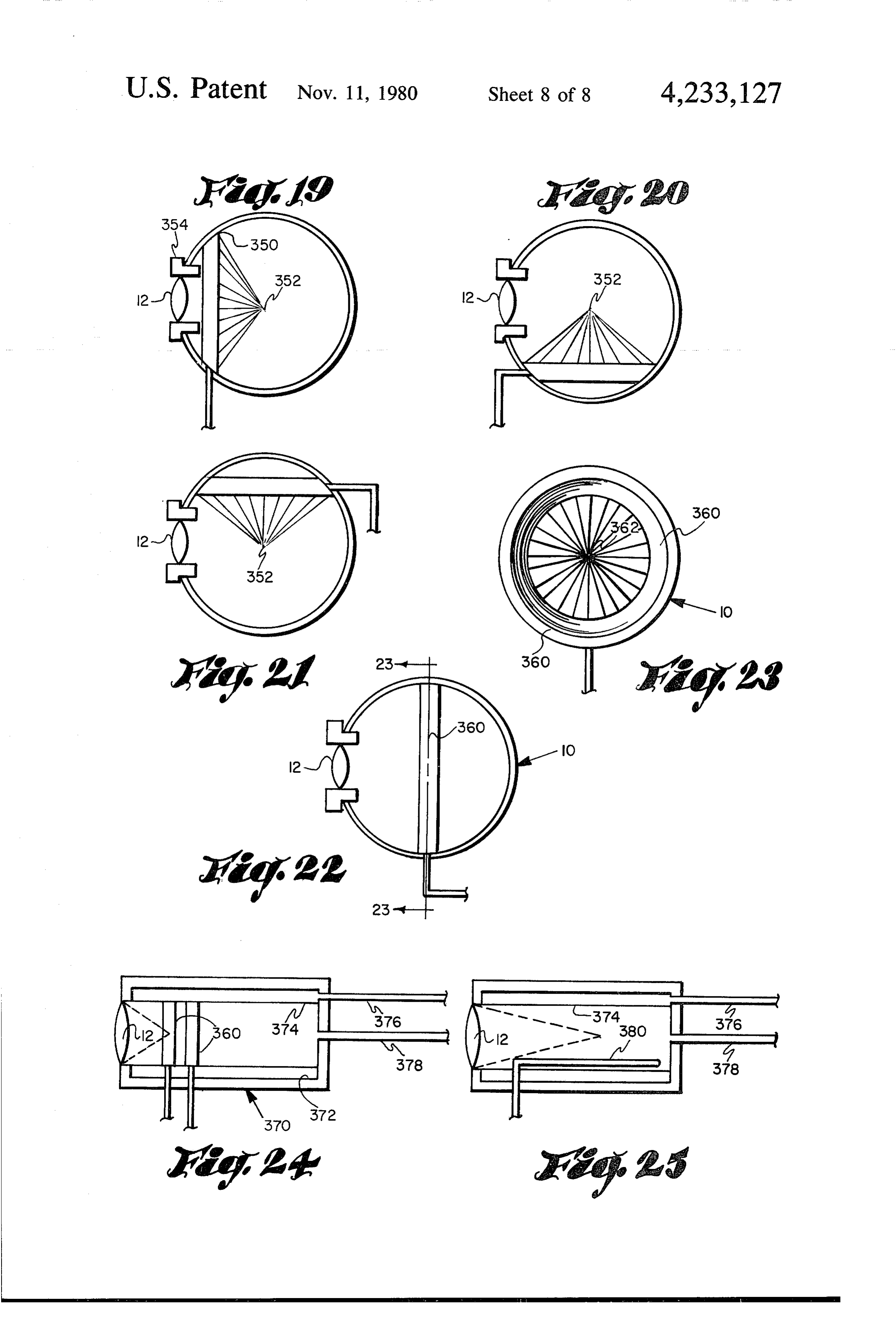
By focusing the light rays at a point within the reac 6. A process according to claim 1 wherein dissocia tion chamber, there is less likelihood of failure of the tion is accomplished at least partly by wave form irradi construction materials of the reactor vessel itself, than if ation. , the rays were allowed to focus at or near a chamber 35 7. A process according to claim 1 wherein both the wall. infra-red wave lengths and the near ultra-violet wave As an alternative to the spray head 30 of FIG. 1, a lengths of the light spectrum are concentrated within spray ring may be utilized as shown in FIGS. 19 said reaction chamber.
through 23. This spray ring 350 has a multiplicity of 8. A process according to claim 1 further comprising spray jets directed toward the focal point 352 of lens 12. 40 separating dissociated hydrogen from oxygen by diffu The spray ring can be located to surround lens sleeve sion of hydrogen through a hydrogen-permeable mem 354 as shown in FIG. 19 or it can be situated in the brane.
bottom of the reactor as shown in FIG. 20 or in the top 9. A process according to claim 1 wherein said disso of the reactor as shown in FIG. 21 or in any other de ciated hydrogen and oxygen is removed from said sired location. By locating the spray ring out of the 45 chamber as a gas mixture at high temperature prior to direct rays of light, it will have a longer useful life. The separating the gases.
spray ring 360 of FIG.22 fits the internal circumference 10. A process according to claim 1 further comprising in the center of the spherical configuration of reactor separating dissociated oxygen from hydrogen by diffu 10. In this case, the spray jets are directed inwardly sion of oxygen through an oxygen-permeable mem toward the focal point 362 of lens 12 as shown in FIG. 50 brane.
23. 11. A process according to claim 9 further comprising As an alternative to the spherical reactor of FIG. 22, separating said hydrogen from said oxygen by .com a tubular reactor can be employed as shown in FIG. 24 pressing the dissociated gas mixture to the liquid state, or 25. Tubular reactor 370 has a water cooled jacket 372 followed by reverse distillation and collection of hydro and a focal lens 12. Inside the reactor 370 are one or 55 gen and oxygen as cryogenic liquids. more spray rings 360 within a hydrogen permeable 12. A process according to claim 9 wherein separation membrane 374. Hydrogen is removed via line 376 and of said gases is accomplished by gravity separation. oxygen and other impurities are removed via line 378. 13. A process according to claim 1 furher comprising Another alternative spray apparatus is depicted in FIG. preheating said waterprior to injecting it into said reac 25 wherein an elongated spray pipe 380 is situated 60 tion chamber, whereby waste heat and rejected energy within the hydrogen permeable membrane, 374, and of recombination is utilized.
directs spray jets into the region of the point of focus of 14. A process according to claim 1 wherein said rays lens 12. are focused at a point within said chamber, said point It can readily be seen from the foregoing that this being spaced from any structural element. invention provides a means for obtaining elemental 65 15. A process according to claim 14 wherein said hydrogen in gaseous or liquid form or as a solid com point is substantially central in said chamber. pound for use in other processes at a very low cost by 16. A process according to claim 1 characterized by employing solar energy as well as providing a means for defocusing said rays on a focusing lens in the wall of
Page 16
said chamber and focusing said rays at a point within 27. Apparatus according to claim 17 wherein said said chamber and spaced from said wall. chamber has a generally spherical configuration. 17. Apparatus for generating hydrogen and oxygen 28. Apparatus according to claim 17 wherein said gas from water, comprising: separating means comprises a tank having a gas mixture (a) a refractory-lined, high temperature reaction inlet, a hydrogen permeable membrane dividing said chamber; tank into a first compartment containing said inlet and (b) a solar collector for collecting the sun's rays; an oxygen outlet, and a second compartment containing (c) means including a focusing lens for directing said a hydrogen
outlet.
Apparatus according to claim 28 wherein said rays through said lens into said chamber and con 10 membrane is tubular in configuration. centrating said rays at a point therein; 30. Apparatus according to claim 17 wherein said (d) means for injecting water into said chamber; chamber is lined with a reflective high temperature (e) means for removing gases from said chamber; refractory.
(f) gas separating means; and (g) means communicating with said gas removal 15 ing31.water A high temperature reaction chamer for dissociat into hydrogen and oxygen, said chamber means for feeding said gas to said separating means. having a heat 18. Apparatus according to claim 17 wherein said water cooling resistant jacket in focusing lens in its outer wall, a its outer wall, means for intro chamber includes a wall having a water-cooling jacket ducing water to the interior therein, and said focusing lens is positioned in the cham for withdrawing dissociatedofgases said chamber, and means therefrom.
ber wall. 20 32. Apparatus according to claim 31 wherein said 19. Apparatus according to claim 18 wherein said lens focusing lens is constructed of a material with a low is seated in a water-cooled lens sleeve. absorption coefficient and a high transfer efficiency of 20. Apparatus according to claim 18 wherein said the natural light spectrum including the ultraviolet and chamber has a generally cylindrical configuration with infra-red wave lengths.
said lens in the end wall of said chamber. 25 33. Apparatus according to claim 32 wherein said lens 21. Apparatus according to claim 18 further compris material is selected from the group comprising quartz ing means for preheating water provided to said inject and flurospar.
ing means. 34. Apparatus according to claim 31 wherein said 22. Apparatus according to claim 21 wherein a source water introducing means comprises at least one annular of demineralized water is connected to said water-cool 30 ring having a multiplicity of spray jets directed toward ing jacket and said jacket communicates with said inject the center of the chamber.
ing means. 35. Apparatus according to claim 31 wherein said 23. Apparatus according to claim 18 wherein said chamber is a cylinder with said focusing lens in its end solar collector is a multiplicity of heliostats positioned wall, and said water introducing means is an elongated to direct solar rays into a reflector positioned to con 35 pipe with said chamber parallel with the axis of said duct the collected rays through said lens. cylinder, and having a multiplicity of orifices for direct 24. Apparatus according to claim 23 wherein said ing water jets toward the axis of said cylinder. heliostats are mounted on a circular track about said 36. Apparatus according to claim 31 wherein said reflector and are movable on said track. chamber includes a permeable membrane therein for 25. Apparatus according to claim 23 wherein at least separating the dissociated gases and said chamber has one heliostat is mounted in each quadrant about said separate hydrogen and oxygen removal means. reflector. 37. Apparatus according to claim 36 wherein said 26. Apparatus according to claim 23 wherein said permeable membrane is tubular.
heliostats are mounted in successive rows, each row 38. Apparatus according to claim 32, wherein said more distant from said reflector at a higher elevation 45 focusing lens is constructed
ofskan xkinorganic material.
than the previous row.
Provenance
- Collection
- Cited prior art
- Original PDF
- patentimages.storage.googleapis.com →
- Filed
- 1978-10-02
- Pages
- 16
- Method
- pdftotext (the PDF's own text layer) + pdftoppm 300dpi page scans
- Source
- Google Patents bibliographic record
- Granted
- 1980-11-11
- Inventors
- Daniel E. Monahan
- Transcribed from
- patentimages.storage.googleapis.com →