patent · US4432344
Method and apparatus for solar destruction of toxic and hazardous materials
21 February 1984
Page 1 — bibliographic record
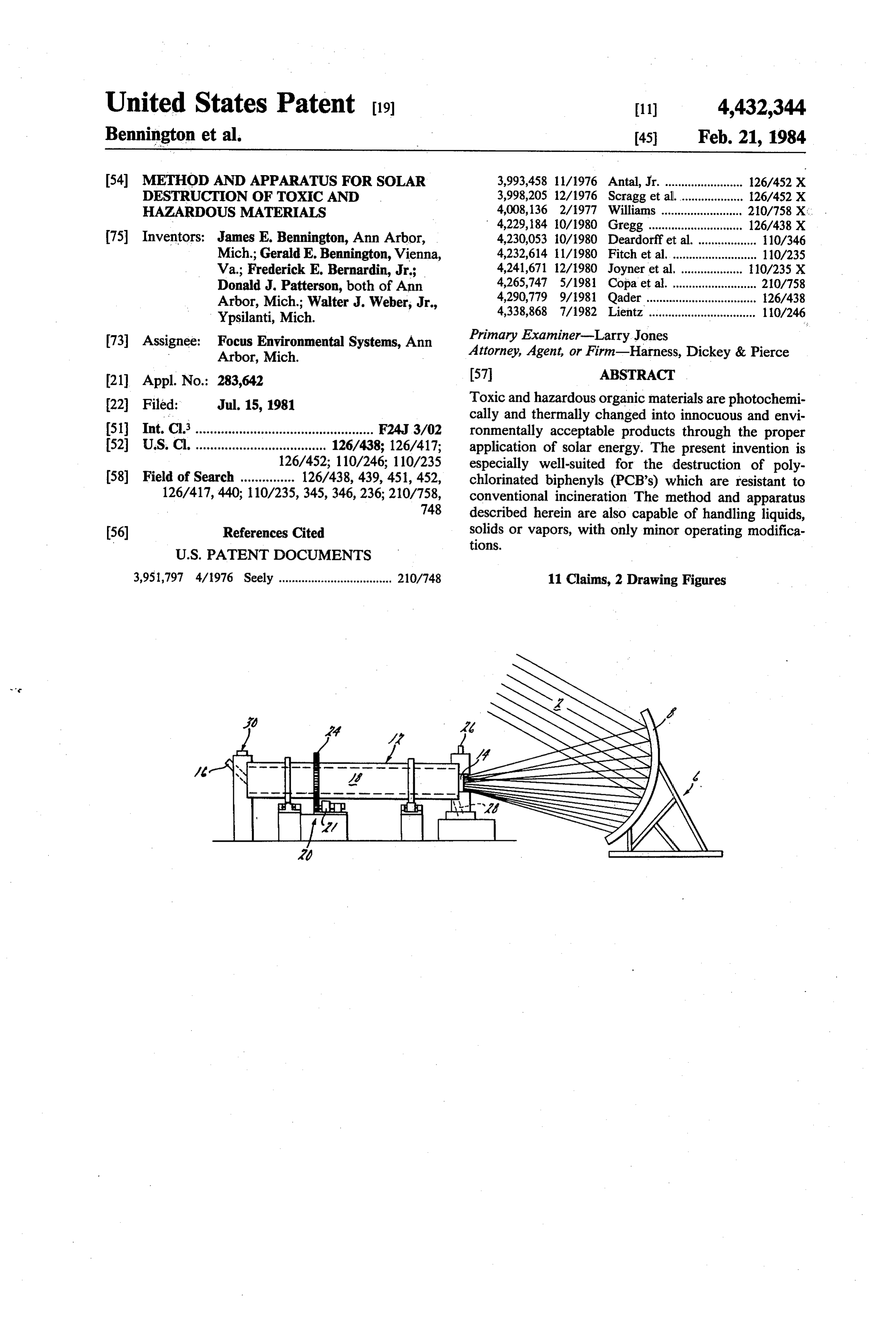
United States Patent (19) 11) 4,432,344 Bennington et al. (45) Feb. 21, 1984 (54) METHOD AND APPARATUS FOR SOLAR 3,993,458 11/1976 Antal, Jr. ........................ 126/452 X DESTRUCTION OF TOXC AND 3,998,205 12/1976 Scragg et al.................... 126/452 X HAZARDOUS MATER ALS 4,008,136 2/1977 Williams ....... 210/758 X. 4,229, 184 10/1980 Gregg ............... ... 126/438 X (75) Inventors: James E. Bennington, Ann Arbor, 4,230,053 i0/1980 Deardorff et al. .................. 10/346 Mich; Gerald E. Bennington, Vienna, 4,232,614 11/1980 Fitch et al............................ 110/235 Va.; Frederick E. Bernardin, Jr.; 4,241,671 12/1980 Joyner et al. . ... 10/235 X Donald J. Patterson, both of Ann 4,265,747 5/1981 Copa et al........................... 210/758 Arbor, Mich.; Walter J. Weber, Jr., 4,290,779 9/1981 Qader .................................. 126/438 Ypsilanti, Mich. 4,338,868 7/1982 Lientz ................................. 110/246 73 Assignee: Focus Environmental Systems, Ann Primary Examiner-Larry. Jones
Arbor, Mich. Attorney, Agent, or Firm-Harness, Dickey & Pierce 21 Appl. No.: 283,642 57 ABSTRACT 22 Filed: Jul. 15, 1981 Toxic and hazardous organic materials are photochemi cally and thermally changed into innocuous and envi (51) Int. C.’................................................. F24J 3/02 ronmentally acceptable products through the proper (52) U.S.C. .................................... 126/438; 126/417; application of solar energy. The present invention is 126/452; 110/246; 110/235 especially well-suited for the destruction of poly 58 Field of Search ............... 126/438, 439, 451, 452, chlorinated biphenyls (PCB's) which are resistant to 126/417, 440; 110/235,345, 346,236; 210/758, conventional incineration The method and apparatus 748 described herein are also capable of handling liquids, (56) References Cited solids or vapors, with only minor operating modifica tions.
3,951,797 4/1976 Seely ................................... 210/748 11 Claims, 2 Drawing Figures
Page 2
Drawing sheet — no readable text.
Page 3
A further object of this invention is to use the high
METHOD AND APPARATUS FOR SOLAR intensity specific wavelength energy present in concen DESTRUCTION OF TOXC AND HAZARDOUS trated sunlight to break chemical bonds and accelerate MATER ALS decomposition of chemical compounds. The present invention also has the object using the intense thermal
BACKGROUND AND SUMMARY OF THE energy present in sunlight to obtain temperatures in INVENTION excess of those created by combustion systems, which
In the great burst of technology since the 1940's, temperatures rapidly decompose chemical compounds. Still another object of this invention is to obtain these many hundreds of thousands of useful chemical com O high temperatures but also minimize the requirement pounds have been synthesized and produced by indus try. Advances in the fields of analytical chemistry and for mize air or other gaseous throughput so as to also mini the large volumes of exit gas common to combus medicine which followed have shown that many of tion systems. The present invention also has the object these chemicals can have potential toxic and carcino of providing the genic effects in man and that many of these are present 15 liquid or gaseousabove objects in the treatment of solid, materials.
and persistent throughout our environment. One class Photochemical degradation appears to be a primary of chemicals which represent a particularly trouble some problem are those which are resistant or refrac pathway wavelength for natural environmental renewal. Specific energy can be absorbed by certain chemical tory to natural decomposition. Polychlorinated biphe bonds to break these bonds. For a given compound, the nyls (PCB's) are a notorious example of such com change in concentration pounds. These materials, particularly resistant to de time has been found to beofdirectly the organic material over proportional to the composition even under elevated temperature, were original concentration, so that a rate constant can be produced and widely used between 1929 and 1977 in determined to provide an equation. That many products. In pure or very concentrated form, has been found to be directly proportionalrate constant PCB's were used as dielectric fluids in electrical trans 25 sity of the sunlight applied to the concentration inten to the formers and as such, are still in place. Congress banned ganic material. Therefore, the rate of destruction of or of the further PCB production in 1977 after animal tests indi compound is proportional to the intensity of the sun cated that PCB's could cause cancer and other health light.
problems. It has been estemated that 750 million pounds The present invention provides means for contacting of PCB's alone are still in use or present in some form in 30 a compound such as an organic material with sunlight the United States today, with many more times that which is concentrated many thousands of times. level of other potentially harmful organic compounds. The chemical reaction for destruction of an organic In many cases due to a lack of adequate processes or compound equipment, the only acceptable "disposal' method for cifically, themayratebeconstantaccelerated by addition of heat. Spe for a chemical reaction in such chemicals was long-term storage or containment 35 creases in an exponential manner with temperature. For underground. This method is not an adequate ultimate many common reactions, the effect of this relationship disposal technique and has potential for adverse effects is that reaction rates can be double or triple with a on both man and his enviroment. temperature increase of 10 degrees Centigrade. Incineration is a potentially valuable method of dis The present invention provides means for heating the posal of toxic organic materials since it is possible in reaction vessel containing a compound such as an or theory to oxidize the compounds to CO2, H2O, SO2, ganic material and permits doing so without an external NO2, and other innocuous or easily handled materials. combustion process or other man-made energy source Operational problems, the use of fossil fuels, the neces which may add materials which in turn would have to sity of high volumes of gas flow, and, perhaps most be safely exhausted. The present invention may, as an important, the resistance of some compounds-particu 45 alternative, be used to supplement a man-made energy larly PCB's-to oxidation under conventional operating SOCC conditions have limited the use of incineration as a dis Other objects and advantages of the instant invention posal method. will be apparent in the following specification, claims Chemical reaction of toxic materials to render them and drawings.
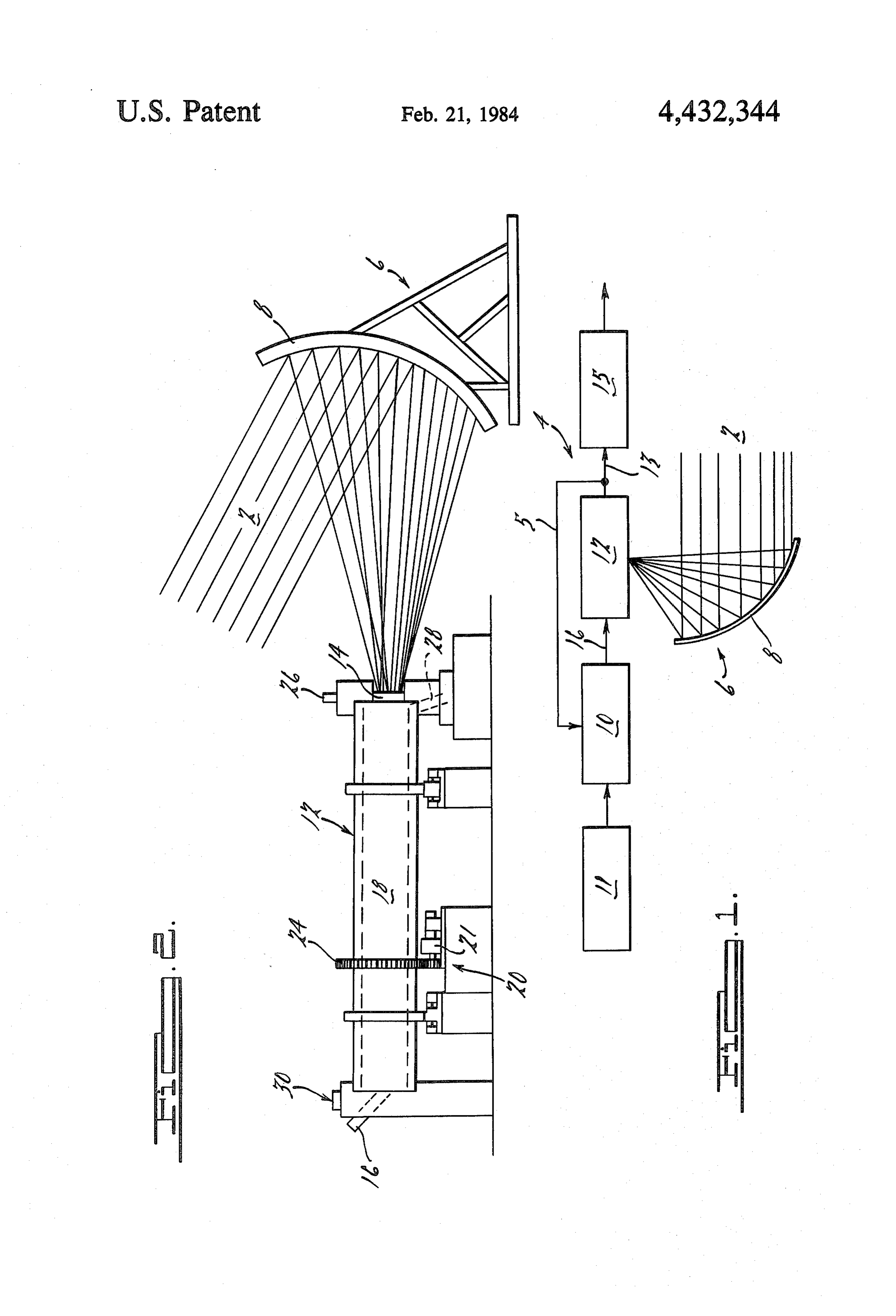
harmless is a method of some value in detoxification. It 50 has long been the method of choice for many inorganic BRIEF DESCRIPTION OF THE DRAWINGS materials, such as metals and cyanides, and has obvious FIG. 1 is a schematic view of a complete system for. potential for use in organic treatment. Chemical meth destruction of toxic and hazardous wastes as included in ods suffer, however, from high cost requirements for the present invention; and close control of processes and the potential for unex 55 FIG. 2 is an elevated view of a reactor apparatus of pected byproducts. the present invention.
The present invention is characterized by a solar DETAILED DESCRIPTION OF THE collector concentrating and focusing the sun's energy PREFERRED EMBODIMENTS into a reaction vessel which is capable of containing and mixing solids, liquids, orgases and exposing these mate FIG. 1 illustrates a complete system 4 in which a rials to the solar energy for a time sufficient to accom portion of the exhaust gas from a solar reactor 12 is plish breakdown of chemical bonds. The hazardous and conducted via a conduit 5 to preheat the incoming ma toxic wastes or the decomposition products can then be terial via a preheat mechanism 10 illustrated schemati further reacted with, for example, oxygen, to complete cally. The preheat mechanism 10 would be located in a the destruction process. Thus, a principal object of the 65 position before a feed port 16 of the reactor 12, with a present invention is to provide a method for destruction feed mechanism 11 disposing hazardous or toxic materi of hazardous and toxic materials through the applica als into the preheat mechanism 10. The feed mechanism tion of concentrated solar energy. 11 may also provide the function of collection and con
Page 4
centration of hazardous or toxic materials prior to feed provided by a drive mechanism 20, including a motor ing the materials to the preheat mechanism 10. The 21, drive pinion 22 and ring gear 24. Feed material remaining portion of the exhaust gas and/or ash is con proceeds the length of the reactor 12 toward and veyed to treatment facilities 15 by conduit 13 where through the source of the concentrated solar radiation conventional vapor/solid phase treatment technology is prior to exiting the reactor 12 at the exhausting means employed to prevent possible contamination of the en for the effluents and byproducts, discharged as a vapor vironment by particulate or residual compounds, releas at vapor discharge port 26 or an ash or other solid at the ing safe byproducts indirectly or directly to the envi lower gravity discharge port 28. If desired, reaction gas ronment and returning toxic or hazardous byproducts may be added to the reactor 12 through port 30 to facili to a storage area and/or to the feed mechanism 11 or to 10 tate the waste destruction process, the residual of which an additional process. reaction gas will also be exhausted at discharge port 26. Solar radiation in the form of sun rays 2 is collected, While the above description constitutes the preferred reflected and focused by a solar concentrator 6, consist embodiments of the present invention, it will be appre ing of at least one curved mirror 8 and a suitable track ciated that the invention is susceptible to modification, ing system necessary for effective operation. As illus 15 variation and change without departing from the proper trated, collected solar radiation is focused to a specific scope or fair meaning of the accompanying claims. working point or area in the reactor 12. The reactor 12, What is claimed is:
however, can be mounted at the focal points of a single 1. In a system including a working chamber, a concentrator or may be used with a field of heliostats method for destruction of toxic and hazardous materi and several curved mirrors 8. The reactor 12 may be 20 als, comprising:
one reactor vessel or a series of reactor vessels, as de feeding said materials into a working chamber; sired, with an individual focal working point in each collecting and filtering solar energy and focusing said vessel. Each vessel may also have its own solar concen filtered solar energy into said working chamber to trator 6 or a solar concentrator 6 may be adjusted to directly act upon said materials in said working focus seriatim on individual vessels. 25 chamber; and
As an alternative embodiment of the present inven exhausting the byproducts of said materials out of tion, exit gas from the solar reactor 12 can be used to said working chamber while minimizing any need vaporize organic material from the sample to be treated. for any large volumes of gaseous throughput Vapors are then conducted to the solar reactor 12 through said working chamber. where they are contacted with the concentrated solar 30 2. A method in accordance with claim 1, further energy and reacted to produce innocuous products. comprising the step of preheating said materials prior to The raw material for this process may be in the form feeding said materials into said working chamber. of a solid, liquid or gas. Solids and liquids will require 3. A method in accordance with claim 1, further some pretreatment for volatilization, while gases may comprising the steps of monitoring said byproducts as be fed directly into the solar reactor 12. Solids and 35 the byproducts are exhausted from said working cham liquids may be pure or may contain only a small amount ber, releasing the safe byproducts from the system and of the contaminant to be reacted. Further, the process directing toxic or hazardous byproducts to a safe stor may be used to treat materials collected previously such age area.
as, for example, those materials adsorbed on activated 4. An apparatus for the destruction of toxic and haz carbon which can be removed by heat from the acti ardous materials, said materials having specific chemi vated carbon. cal bonding energies, comprising: Referring now to FIG. 2, an apparatus is illustrated a reactor comprising a reaction chamber, including that can be employed as the solar reactor 12 of the means for withdrawing material from said chamber system 4 for solar destruction of toxic and hazardous and having a reaction zone within said chamber; wastes. Collected solar radiation is focused to a specific 45 a transparent window set in one surface of said reac working point or area in the solar reactor 12 through tor, said window being transparent to solar radia access means comprising a suitable window 14. The tion at the wanelengths corresponding to the bond material of which the window 14 is constructed is such ing energies of said materials; that the material will not filter out the specific wave means for collecting solar radiation, directing solar length radiation necessary for the desired photochemi 50 radiation into said reaction chamber through said cal reactions. One such material for the window 14 is transparent window, concentrating said solar radi quartz. Other materials can be used based on specific ation to within said reaction zone, and focusing radiation energy desired in the reactor 12. The window solar energy in said zone; and 14 is also constructed so that the window 14 may be means for feeding toxic or hazardous materials pri changed to a window of a different material in order to 55 marily by gravity into the interior of said reactor at vary the wavelengths filtered by the window 14 as said reactor zone;
desired for different compounds of pollutants or toxic wherein the high intensity specific wavelength en materials. ergy present in said concentrated sunlight breaks The reactor 12 may be a type of rotating kiln as chemical bonds in said toxic or hazardous materials shown or other device embodying similar features capa and accelerates decomposition of the chemical ble of feeding the materials to a point at which focused compounds of said toxic or hazardous materials, solar energy may act upon the materials. Solids, liquids degrading said compounds in direct proportion to or vapor feed material is fed to the reactor 12 at the feed the original concentration of the compounds. port 16 to enter an insulated working chamber 18 which 5. A claim in accordance with claim 4, wherein said may contain flights or blades to provide mixing of the 65 window is composed of a quartz material. feed material, and may be aided by a gravity feed by 6. A claim in accordance with claim 4, further com means of a slight angulation of the reactor 12. In the prising a rotating reactor which includes said working illustrated embodiment, rotation of the reactor 12 is chamber and has said solar energy access means dis
Page 5
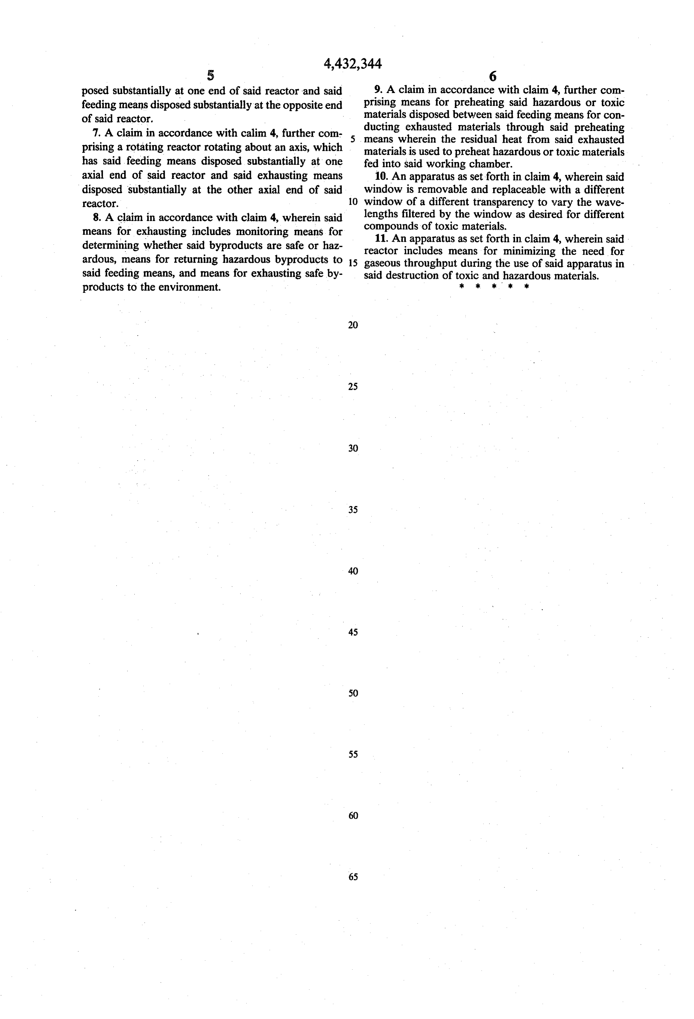
posed substantially at one end of said reactor and said 9. A claim in accordance with claim 4, further com feeding means disposed substantially at the opposite end prising means for preheating said hazardous or toxic of said reactor. materials disposed between said feeding means for con 7. A claim in accordance with calim 4, further com ducting exhausted materials through said preheating means wherein the residual heat from said exhausted prising a rotating reactor rotating about an axis, which materials is used to preheat hazardous or toxic materials has said feeding means disposed substantially at one fed into said working chamber. axial end of said reactor and said exhausting means 10. An apparatus as set forth in claim 4, wherein said disposed substantially at the other axial end of said window is removable and replaceable with a different reactor. 10 window of a different transparency to wary the wave 8. A claim in accordance with claim 4, wherein said lengths filtered by the window as desired for different means for exhausting includes monitoring means for compounds of toxic materials.
11. An apparatus as set forth in claim 4, wherein said determining whether said byproducts are safe or haz reactor includes means for minimizing the need for ardous, means for returning hazardous byproducts to 15 gaseous throughput during the use of said apparatus in said feeding means, and means for exhausting safe by said destruction of toxic and hazardous materials. products to the environment. st k is
Page 6
UNITED STATES PATENT AND TRADEMARK OFFICE
PATENT NO. :
CERTIFICATE
OF CORRECTION
INVENTOR (S) : James E. Bennington, et all
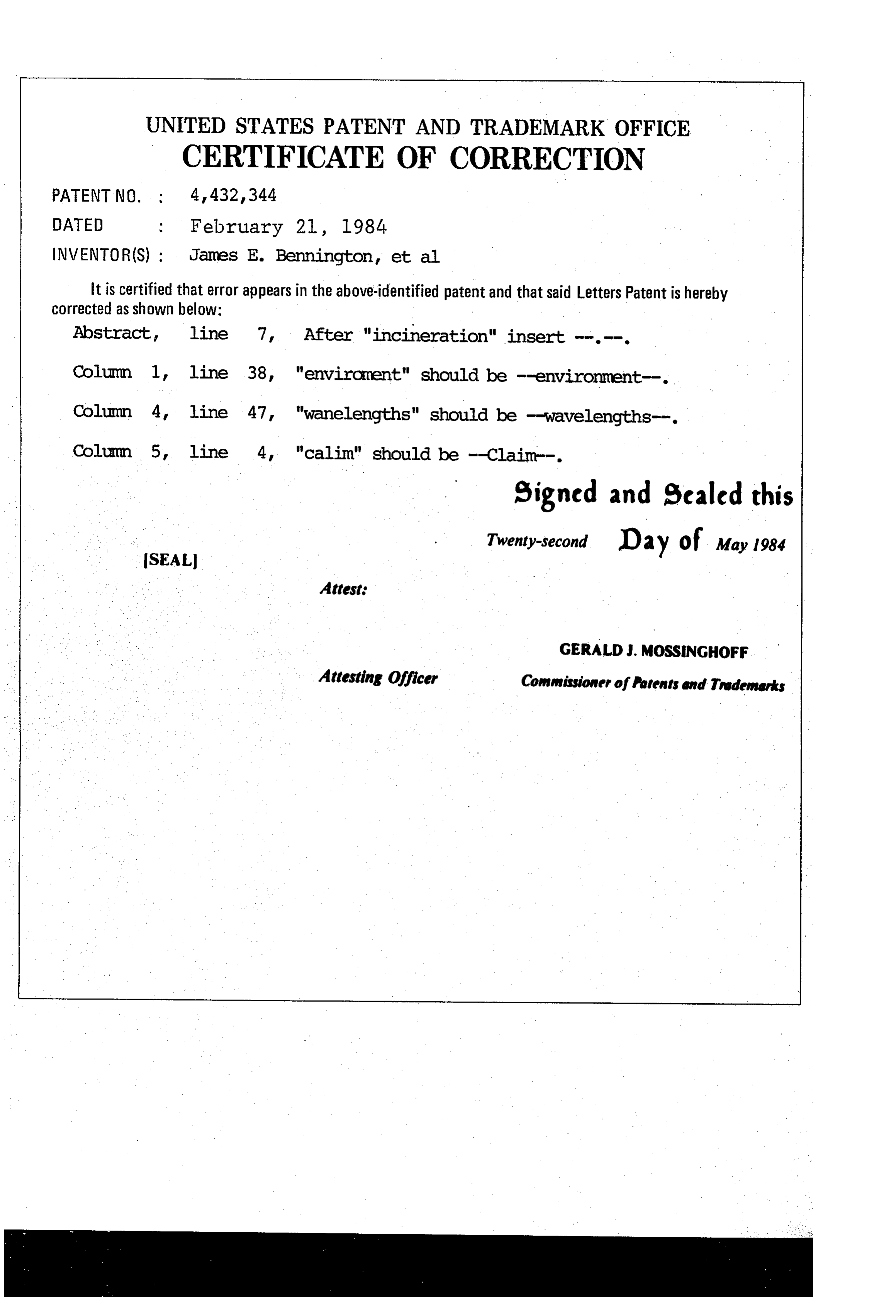
It is certified that error appears in the above-identified patent and that said Letters Patent is hereby corrected as shown below:
Abstract, After "incineration" insert -...-.
Column 1 line 38, "enviroment" should be -environment--. Column 4 line 47, "wanellengths" should be -wavelengths-. "calim" should be -Claim-.
signed and escaled this
SEAL
Attest:
GERALDJ. MOSSINGHoFF
Attesting Officer Commissioner of Patents and Trademarks
Provenance
- Collection
- Cited prior art
- Original PDF
- patentimages.storage.googleapis.com →
- Filed
- 1981-07-15
- Pages
- 6
- Method
- pdftotext (the PDF's own text layer) + pdftoppm 300dpi page scans
- Source
- Google Patents bibliographic record
- Granted
- 1984-02-21
- Inventors
- James E. Bennington; Gerald E. Bennington; Frederick E. Bernardin, Jr.; Donald J. Patterson; Walter J. Weber, Jr.; Focus Environmental Systems
- Transcribed from
- patentimages.storage.googleapis.com →