patent · US4207154
Wave generating apparatus and method
10 June 1980
Page 1 — bibliographic record
United States Patent (19) 11) 4,207,154 Lemelson 45 Jun. 10, 1980 (54) WAVE GENERATINGAPPARATUS AND 57 ABSTRACT
METHOD
An apparatus for reacting on matter with shock waves 76 Inventor: Jerome H. Lemelson, 85 Rector St., which are directed through or against said matter. In Metuchen, N.J. 08840 one form, the shock waves are generated intermittently (21) Appl. No.: 93,779 for an extended period of time, during which time the 22 Filed: Nov.30, 1970 work is subjected to the high temperatures and pres sures of the shock waves. Both chemical and physical
Related U.S. Application Data changes may be effected in the material reacted on by the shock waves, 63 Continuation-in-part of Ser, No. 668,561, Jun. 27, 1957, Where a plurality of shock waves are directed against abandoned.
the same matter to progressively change same, the ap 5ll int. Cl’................................................ B01J 1/12 paratus includes means for amplifying the shock waves 52 U.S. C. ............................. 204/157.1 S; 204/193; to increase the intensity of the individual waves and 204/158 S enhance or improve the reactive effects.
58) Field of Search ............. 204/193, 157.1 S, 158 S; In another form of the invention, a plurality of shock 23/1 R, 252 B, 284, 285 waves are simultaneously generated in different zones (56) References Cited of a reaction chamber and are directed into a reaction
2,745,861 5/1956 Bodine ................................. 204/193 neously subjecting said matter to the heat and pressure 3,348,814 10/1967 Shaw ......................................., 259/1 of each of the shock waves directed thereagainst. Primary Examiner-Howard S. Williams 22 Claims, 53 Drawing Figures
Page 2
Drawing sheet — no readable text.
Page 3
Drawing sheet — no readable text.
Page 4
Drawing sheet — no readable text.
Page 5
Drawing sheet — no readable text.
Page 6
Drawing sheet — no readable text.
Page 7
Drawing sheet — no readable text.
Page 8
Drawing sheet — no readable text.
Page 9
Drawing sheet — no readable text.
Page 10
Drawing sheet — no readable text.
Page 11
Drawing sheet — no readable text.
Page 12
Drawing sheet — no readable text.
Page 13
Drawing sheet — no readable text.
Page 14
degrees Farenheit and may be used as described herein
WAWE GENERATING APPARATUS AND to effect chemical and physical changes in matter sub METHOD jected thereto. One or more lasers or electron guns may be employed and directed to generate one or more
RELATED APPLICATIONS 5 intense beams operable to generate shock waves as This is a continuation-in-part of application Ser. No. described hereafter.
668,561 filed June 27, 1957, for Wave Generating Appa A primary object of this invention is to provide in ratus, now abandoned. provapparatus and methods for generating and apply
ing shock waves to matter.
Yet another object is to provide improved means for
This invention relates to wave generating apparatus generating and augmenting shock waves in reaction and methods for reacting on matter by means of intense chambers by the sudden release of intense radiant en shock waves, which may be generated in gaseous or ergy.
liquid media comprising the matter to be reacted on or Another object is to provide an apparatus and comprising a wave conducting medium which is cou 15 method for generating and augmenting shock waves by pled to the surface of a liquid or solid material or con means of intense arcing or generating sparks in a gase tains matter to which energy is to be transferred by ous or liquid medium.
means of shock waves. Another object is to provide an apparatus and The conventional so-called shock tunnel or shock method for generating and augmenting shock waves in tube provides means for the generation of a single shock 20 a gaseous, liquid or solid medium by generating intense wave therein which shock wave is generally directed radiant energy by means of a laser or electron beam along the tunnel against a model, with the results ob generating gun and directing same into a gas, liquid or served by means of photography for analyzing the aero a solid.
dynamic effects of the model. Such a shock tube is an 25 Another object is to provide an apparatus and elongated metal duct divided by a diaphragm into low method for deforming matter by means of the intense and high pressure regions wherein a driver gas, usually pressures generated by a plurality of shock waves di helium, is released suddenly from the high pressure rected against the matter.
region by puncturing the diaphragm, resulting in the Another object is to provide a shockwave generating development of a shock wave as the gas enters a low 30 apparatus pressure region. Large shock tubes have been devel matter. and method capable of coating or eroding oped in which shock waves have been generated in the Another object is to provide improvements in appa working or low pressure region of the tube in excess of ratus which is applicable for high-temperature reactions 20 times the speed of sound and temperatures associated such as that defined by the apparatus herein. with said shock waves have been observed in excess of 32,000 F. (i.e.-in the wave front of the shock wave). 35 With the above and such other objects in view as may While these devices produce sufficiently high energy hereinafter more fully appear, the invention consists of waves to do work, the short duration of the existence of the novel constructions, combinations and arrange ments of parts as will be more fully described and illus the single shock wave and the effort and time required trated to repeat the action are factors which limit the use of understood in the accompanying drawings, but it is to be such apparatus for test purposes. 40 that changes, variations and modifications may be resorted to which fall within the scope of the
This invention relates to an apparatus and method for invention generating, augmenting and utilizing high-intensity as claimed.
pressure waves such as shock waves directed into reac In the drawings:
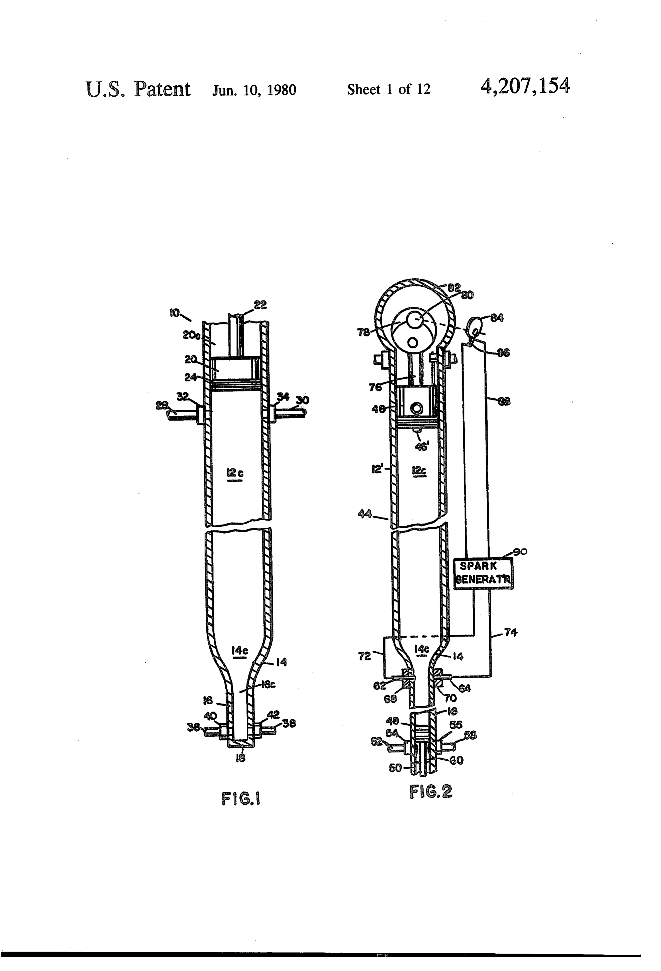
tion chambers for creating chemical and, in certain FIG. 1 is a side view with parts broken away for instances, physical changes in fluids and solids. It is 45 clarity of a wave generating apparatus employing piston known in the art that various chemical reactions which means to generate and amplify compression and shock are difficult or uneconomical to attain at so-called low waves;
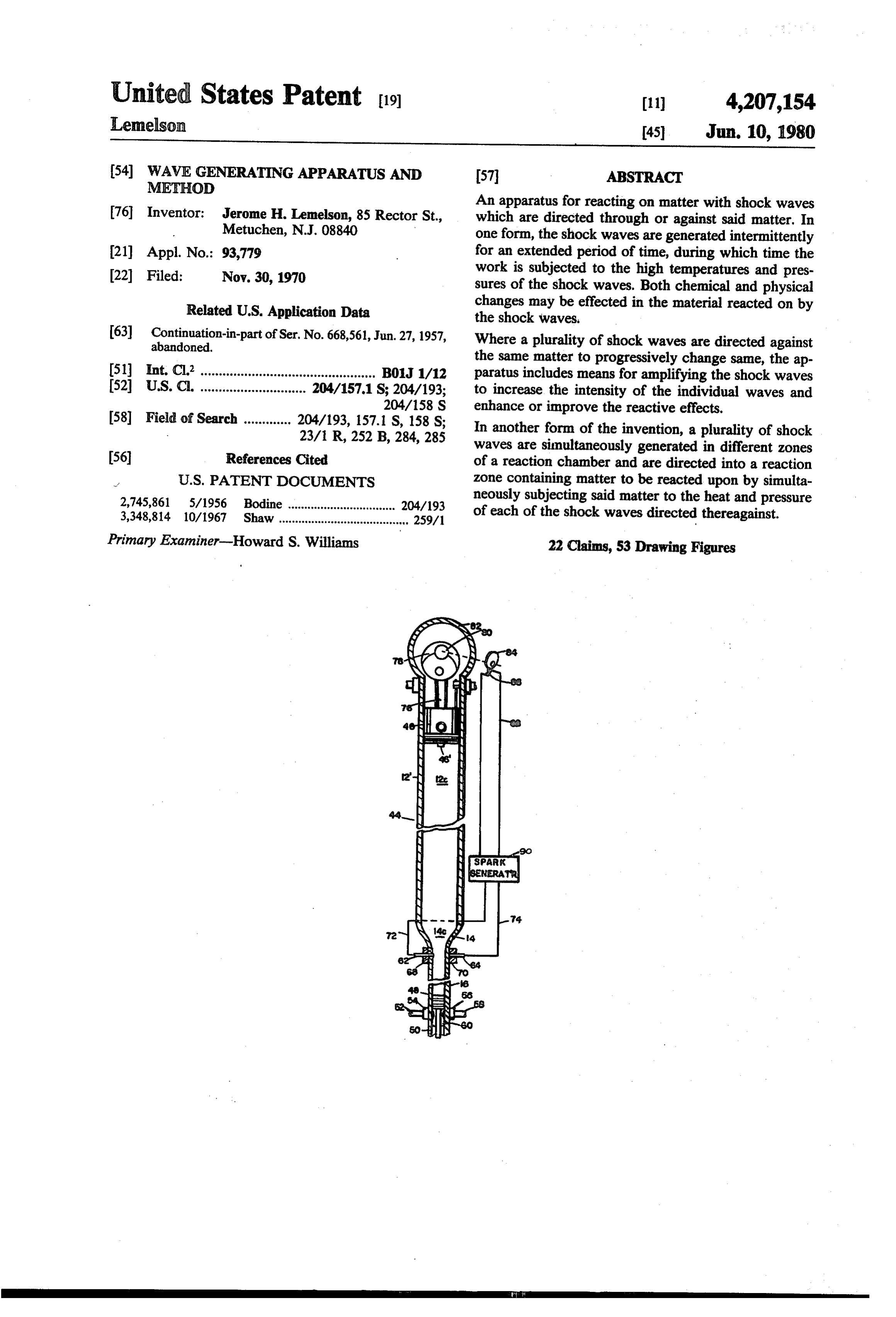
temperatures (below 2500 F) and at pressures in the FIG. 2 is a side view with parts broken away for range of atmospheric pressure can be made to occur clarity of a modified form of the apparatus of FIG. rapidly and efficiently at higher temperatures and pres 50 including spark-generating means for forming and am sures. Certain difficulties are experienced in attempting plifying shock waves;
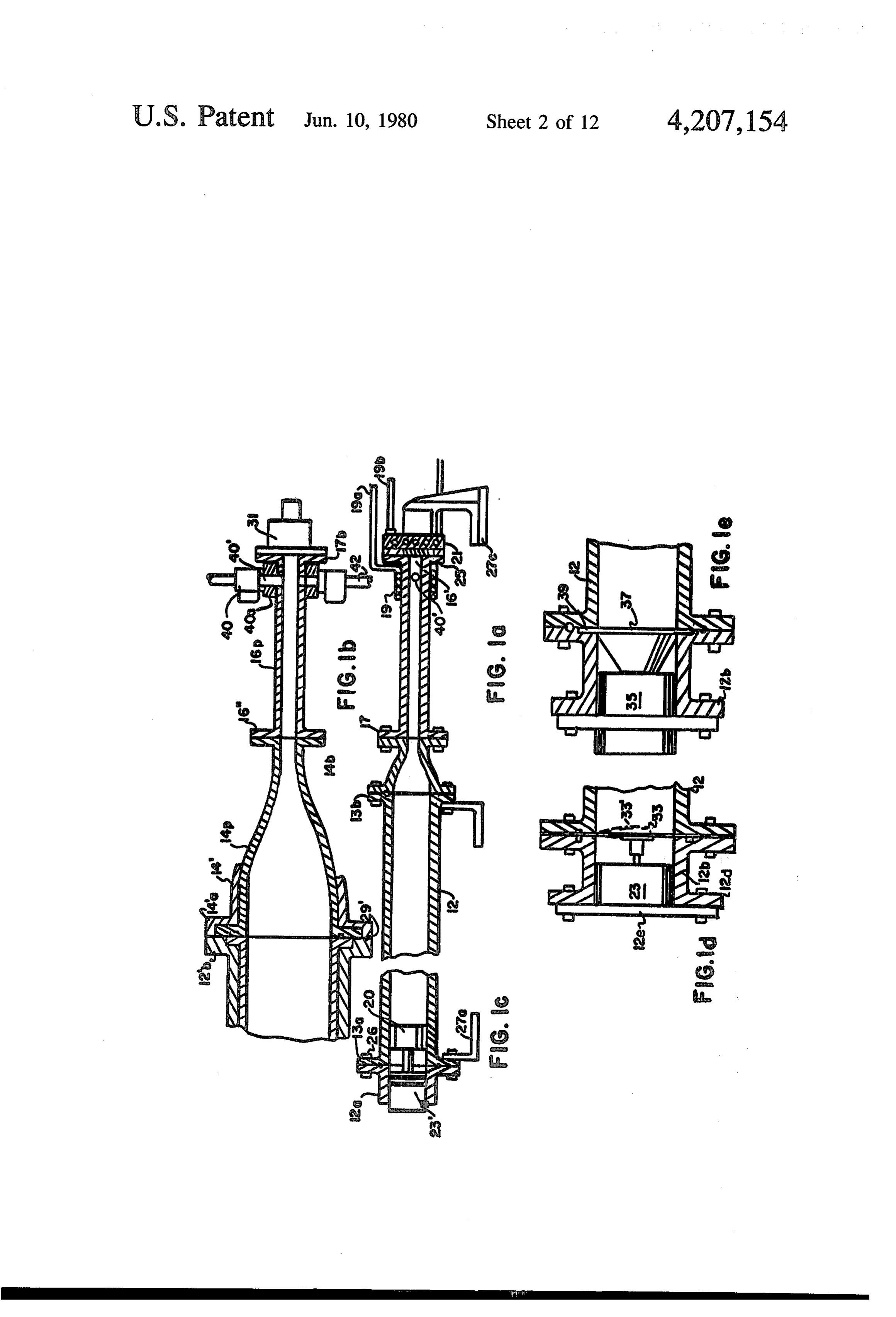
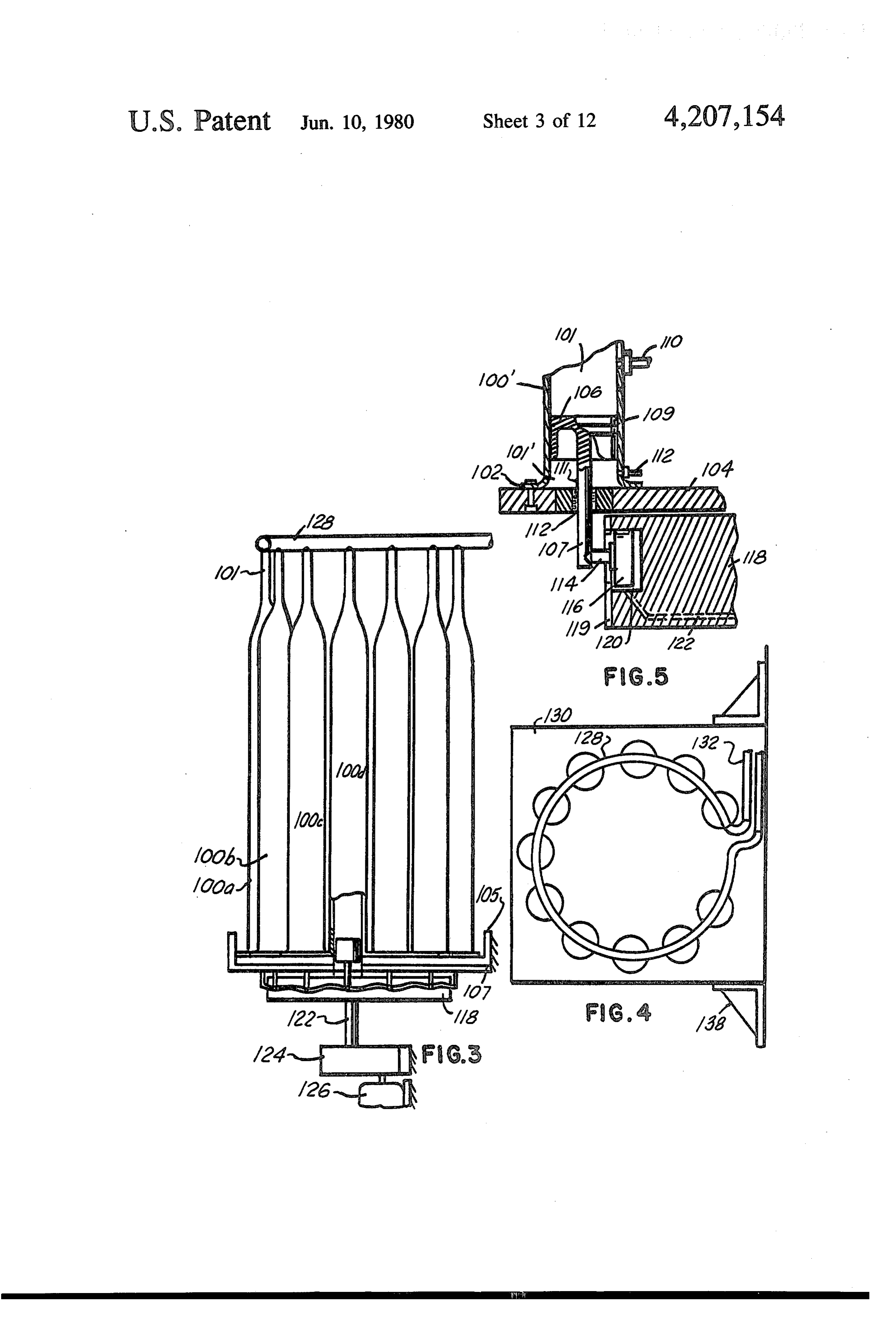
to attain high temperatures and pressure by conven FIG. la is a side view with parts broken away for tional means employing conventional combustion, elec clarity of a modified form of the apparatus of FIG. 1; trical energy, etc. such as energy input requirements, FIG. 1b is a side view with parts broken away for heat corrosion, heat loss in process, and the effects of 55 clarity of a modified form of the apparatus of FIG. 1 a prolonged application of heat to the process chemicals. FIG. Ac is a side view with parts broken away for The instant invention employs one or more means for clarity of a modified form of piston drive means for gas generating one or more shock waves in a fluid medium associated with the apparatus of FIGS. 1 and 2; which may be the so called working fluid, the reacting FIG. d is a side view with parts broken away for fluid or a combination of both intermixed or in interfa 60 clarity of a diaphragm type piston applied to a shock cial relationship with each other such as two gases, a tube of the type illustrated in FIG. 1; gas and and liquid or two liquids in either or both of FIG. lie is a side view with parts broken away for which shock waves are generated and propagated. De clarity showing an ultrasonic whistle connected to a pending on the intensity of the source of the shock wave shock tube; w which may comprise an electrical spark, explosion, 65 FIG. 3 is a side view with parts breken away for mechanical oscillator and amplifying means or one or clarity of a multiple shock tube apparatis; more intense radiation beams, temperatures existing in a FIG. 4 is an end view of an appa fattis ef the type moving shock wave may equal or exceed one million shown in FIG. 3;

Page 15
FIG. 5 is a fragmentary view with parts broken away FIG. 29 is a side-elevational view of a fragment of a for clarity of part of the apparatus of FIGS. 3 and 4; modified form of reaction apparatus of the type shown FIG. 6 is a schematic diagram showing control com in FIGS. 26-28;
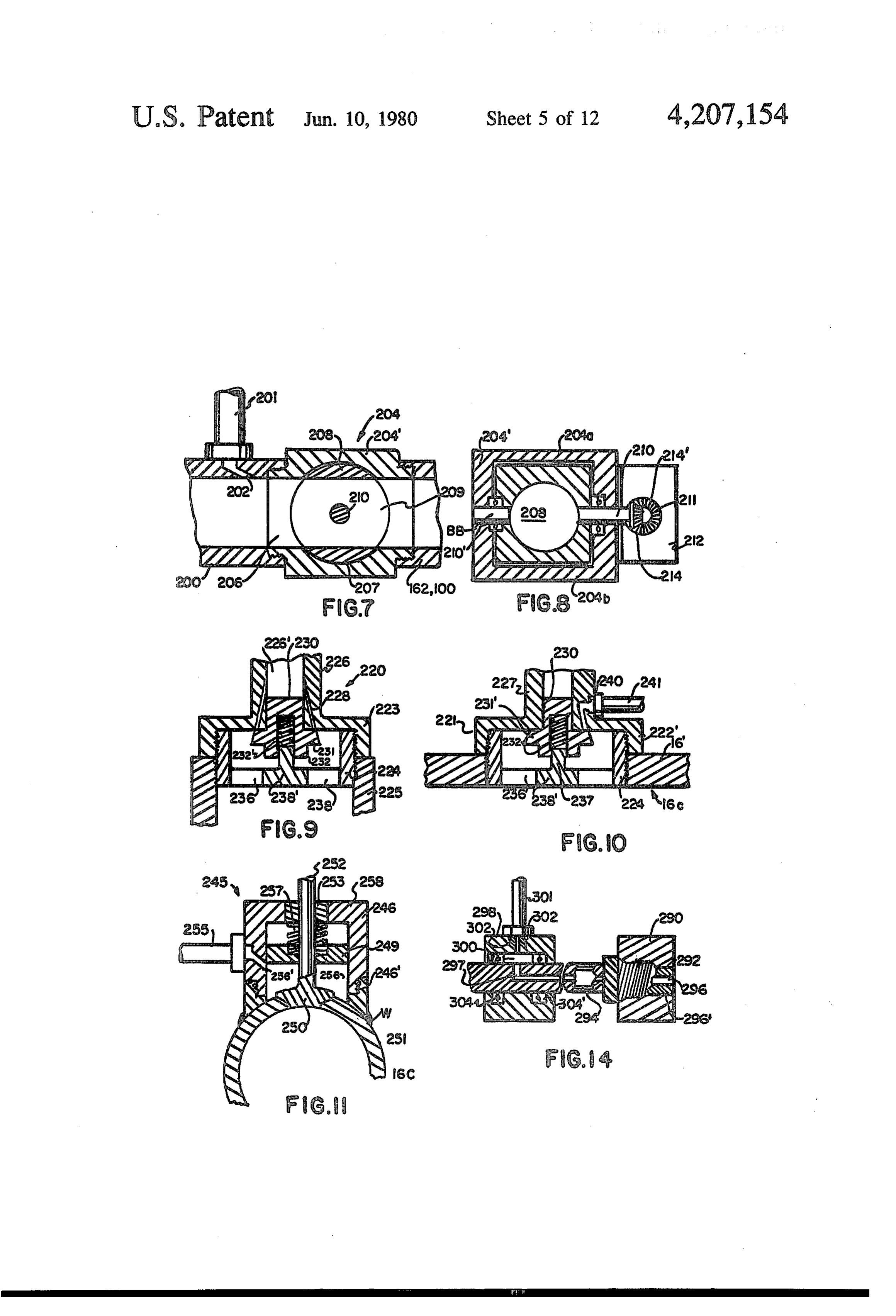
ponents for an apparatus of the type shown in FIGS. FIG. 30 is a side-elevational view of yet another form 1-5; 5 of reaction apparatus employing a free piston to gener FIG. 7 is a cross-sectional side view of a power ate shock waves in a plurality of shock tubes; operated valve applicable to the apparatus of FIGS. FIG. 31 is a fragmentary view of the apparatus of 1-6; FIG. 30 with parts broken away for clarity; FIG. 8 is a cross-sectional view in end elevation of FIG. 32 is a side-elevational view of a modified form the valve of FIG. 7; O of fluid dispensing apparatus employing features of the FIG. 9 is a fragmentary side view in cross-section of invention;
a modified form of valve applicable to the apparatus of theFIG. 33 is a side-elevational view in cross-section of end of a shock tube modified to receive and locate
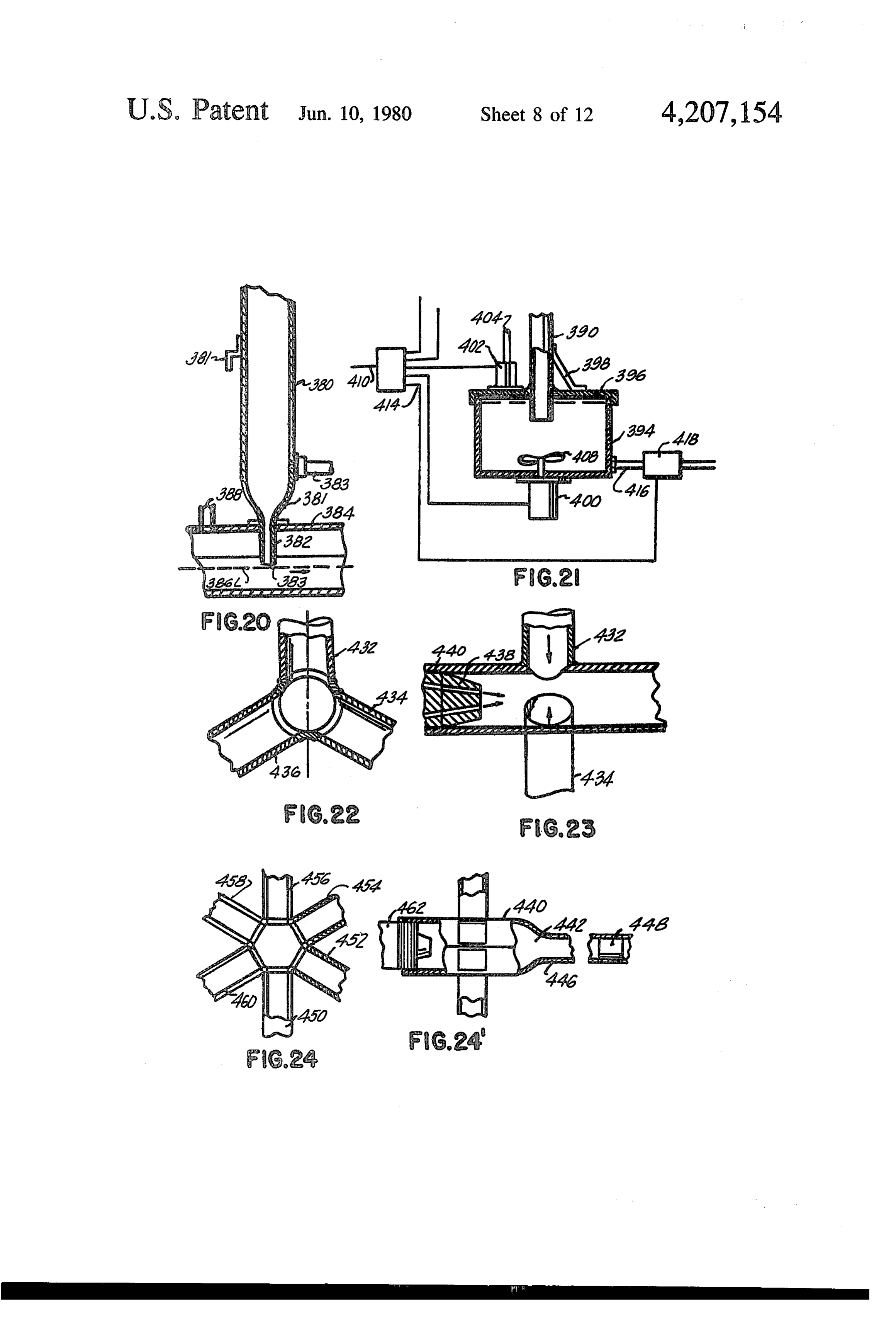
FIG. 10 is a cross-sectioned side view of another form a member to be coated by means of shock waves; of valve applicable to the apparatus of FIGS. 1-6; 15 FIG. 34 is a side-elevational view of a modified form FIG. 11 is a cross-sectional view taken in end eleva of reaction apparatus for reacting on articles disposed on a conveyor;
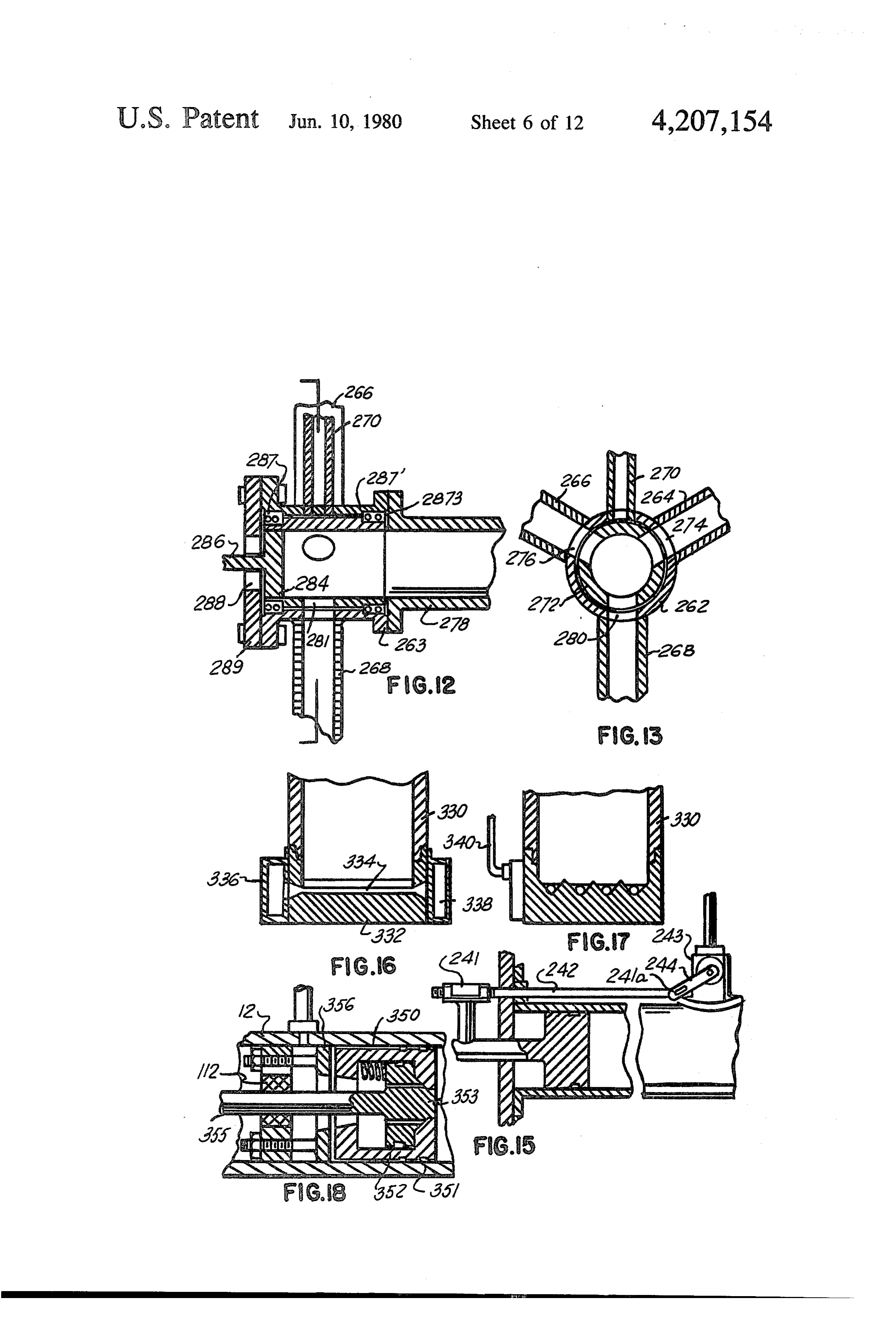
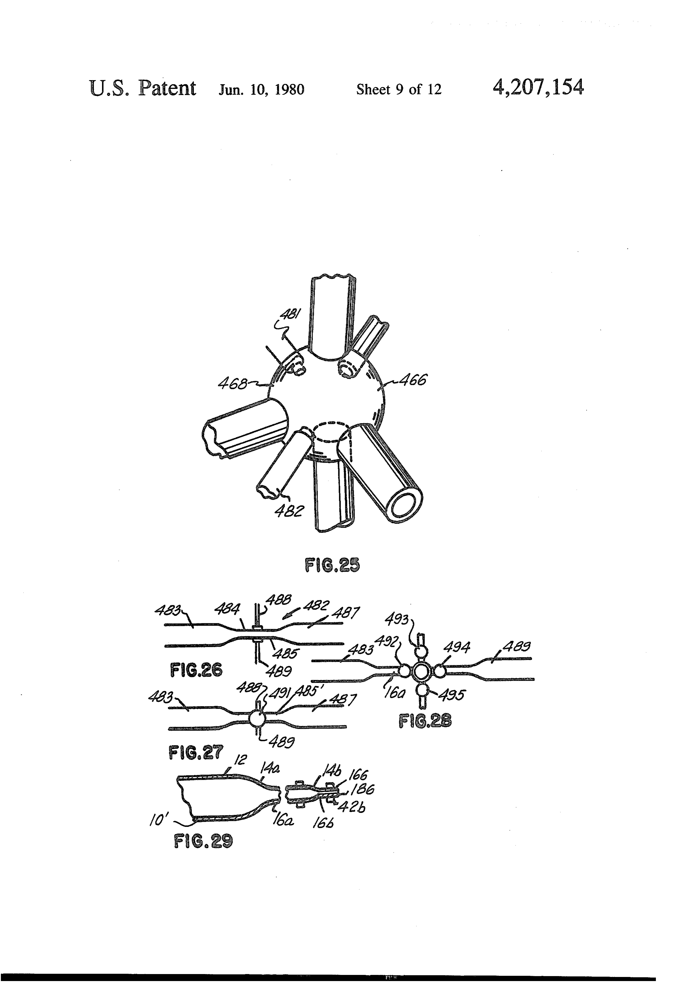
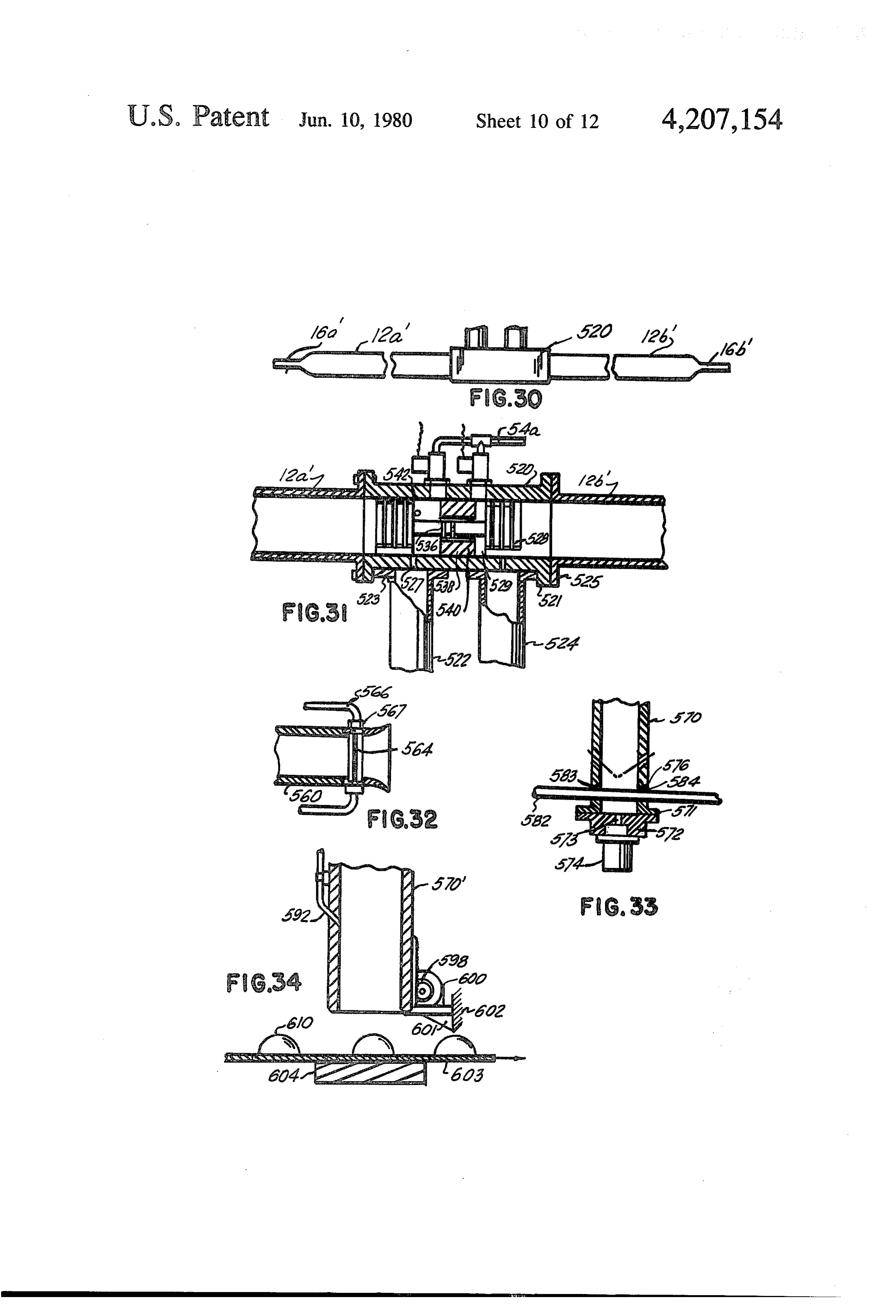
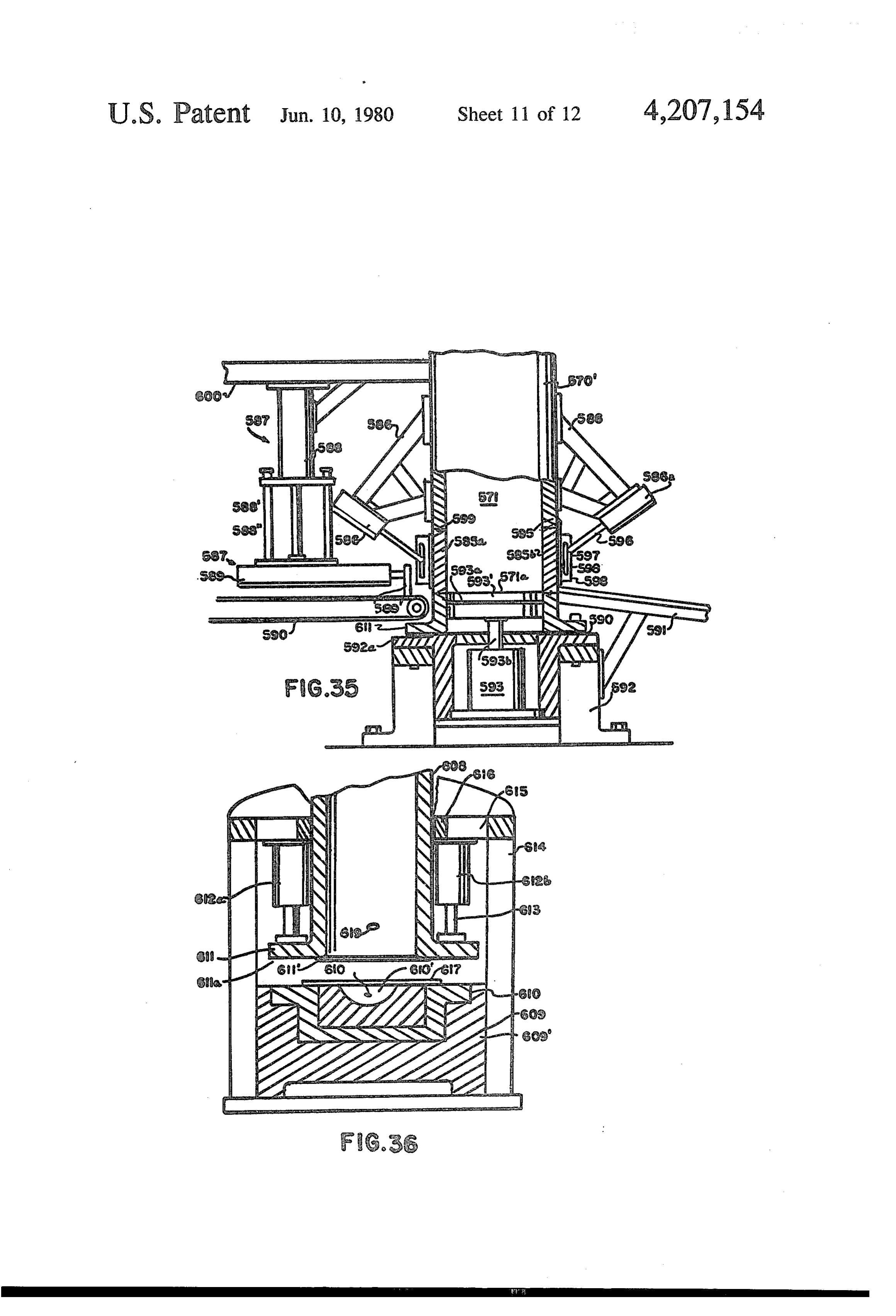
tion of another form of valve application to the appara FIG. 35 is a side view with parts broken away for tus of FIGS. 1-6; clarity of a modified form of reaction chamber for re FIG. 12 is a fragmentary view of a modified form of 20 acting on the end of a shock chamber of the type shown in FIGS. thereto andsmall articles which are automatically fed removed therefrom;
1-6; FIG. 36 is a side view with parts broken away for FIG. 13 is an end elevational view taken in cross-sec clarity of part of a reaction apparatus operable to de tion of the valve of FIG. 12; form sheets and plates into a die; FIG. 14 is a side cross-sectional view of a fluid injec 25 FIG. 37 is a side-elevational view of a reaction cham tor applicable to the apparatus of FIGS. 1-6; ber and an article therein to be coated; FIG. 15 is a side view with parts broken away for FIG. 38 is an end-elevational view with parts broken clarity of the working end of a reaction chamber of the away for clarity of a work piece and a shock wave type shown in FIGS. 2 and 6; generating apparatus coupled thereto; FIG. 16 is a side view in cross-section of the end of 30 FIG. 39 is a side view in cross-section of a modified another form of reaction chamber within the purview of form of piston and spark-generating means applicable to the instant invention; the apparatus of FIG. 2;
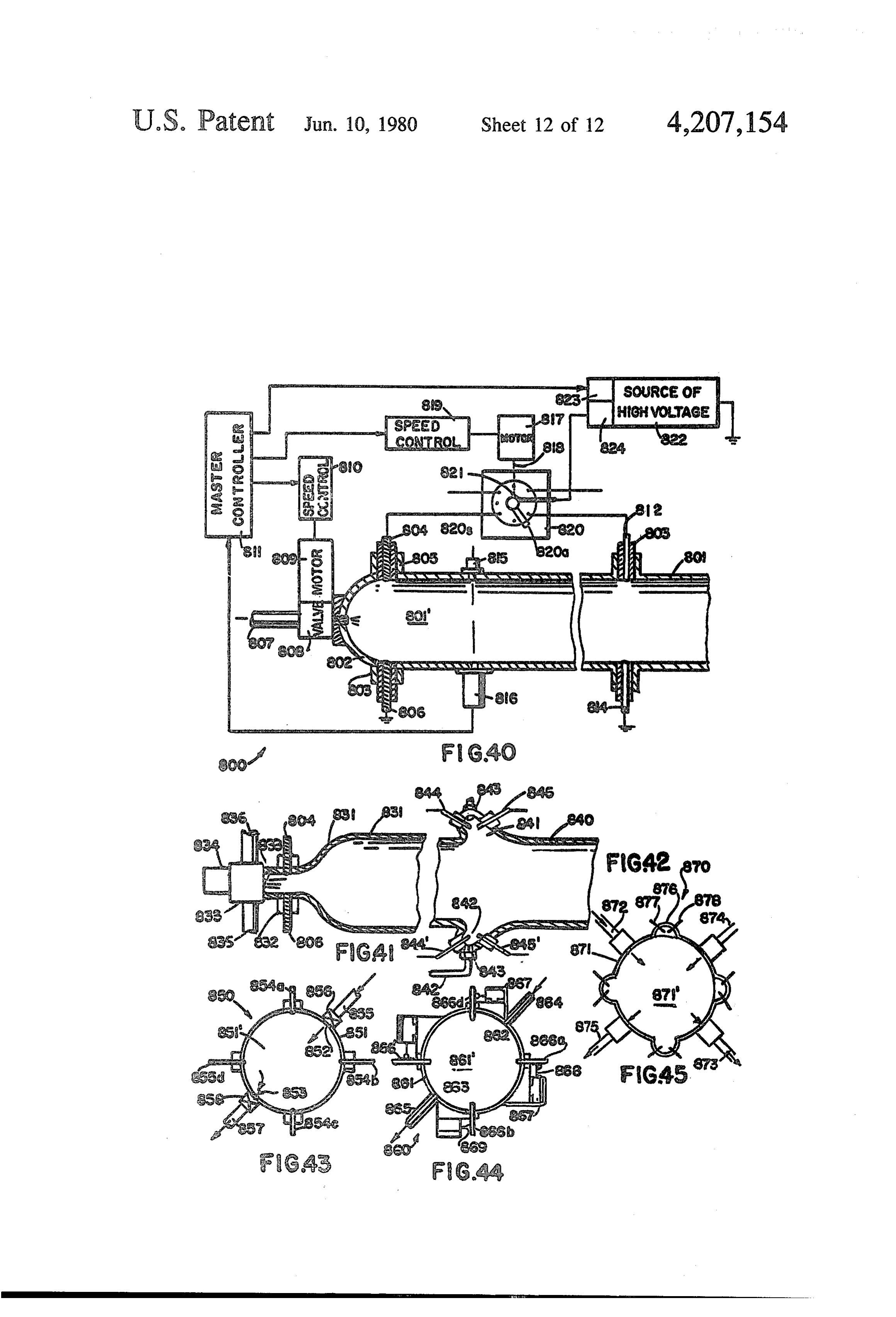
FIG. 17 is a side view in cross-section of yet another FIG. 40 is a side-elevational view of part of a reaction form of reaction chamber; chamber cross-sectioned and provided with spark dis FIG. 18 is a side view in cross-section of a form of 35 charge means for generating and amplifying shock valve applicable to the apparatus of FIGS. 1-6; waves;
FIG. 19 is a side view in cross-section of a timing FIG. 41 is a side view in cross-section of a fragment control applicable to the apparatus of FIGS. 2 and 6; of a modified form of shock wave generating apparatus FIG. 19a is a side view in cross-section of another employing spark discharge means;
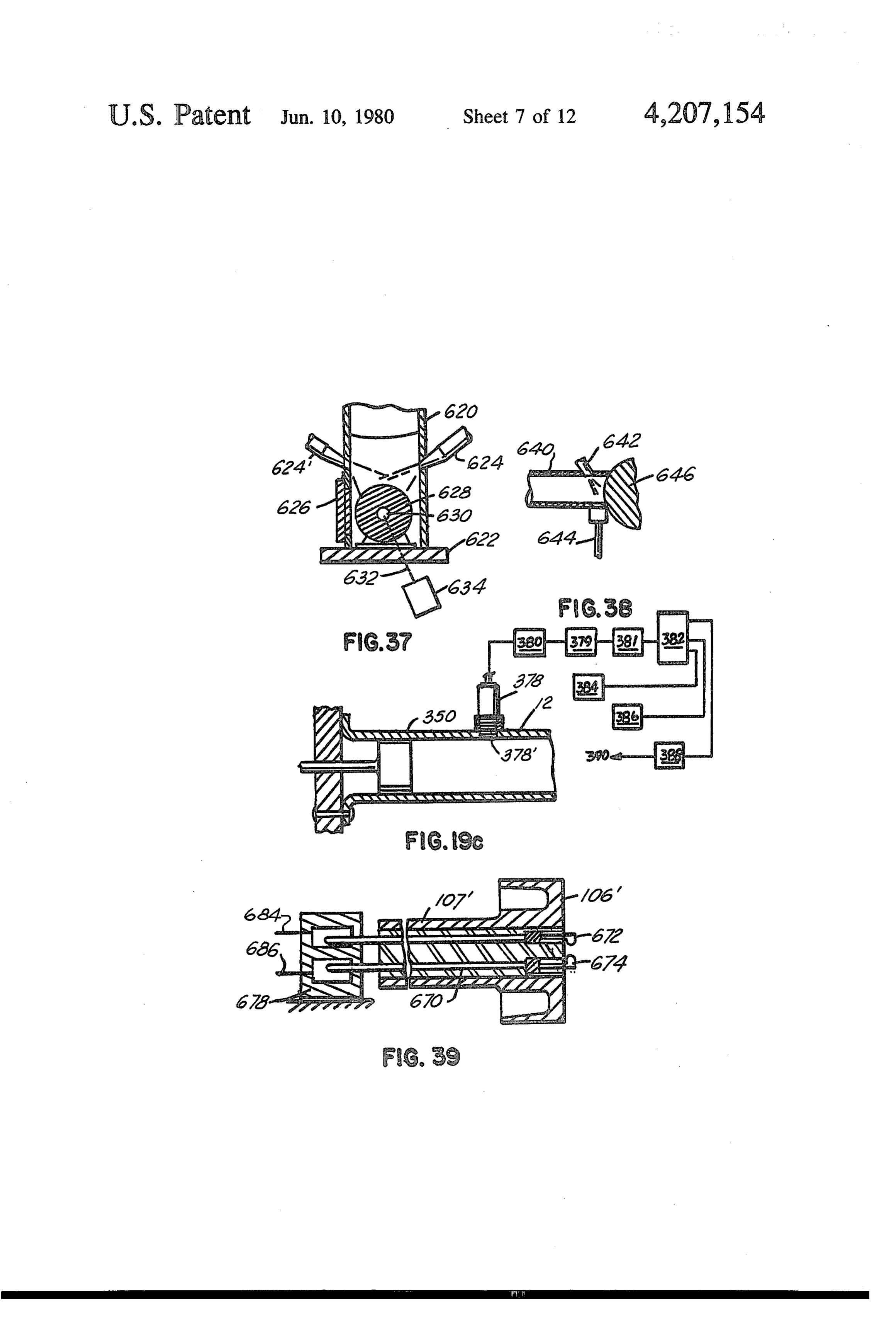
form of timing control; FIG. 42 is a side view in cross-section of a modified FIG. 19C of another form of timing control; form of the apparatus of FIG. 41; FIG. 20 is a side view in cross-section of a modified FIG. 43 is an end elevational view of a modified form form of the apparatus of FIGS. 1, 2 and 6, which is of the apparatus of FIG. 41 and 42;
operable to perform reactions on a liquid in the conduit; 45 FIG. 44 is an end-elevational view of a modified form FIG. 21 is a side view in cross-section of a modified of the apparatus of FIG. 42;
form of the apparatus of FIG. 20; FIG. 45 is an end-elevational view of a modified form FIG. 22 is an end view in cross-section of a reaction of the apparatus of FIG. 44.
chamber employing three shock tubes angulated with areIncreated an important form of the invention, shock waves respect to each other and discharging into a common 50 shock tube in rapid succession in a reaction chamber or and are passed in rapid succession into and reaction zone;
FIG. 23 is a side view in cross-section of the appara through a working region of a said tube to create chemi cal and/or physical changes in matter such as a fluid or tus of FIG.22; fluids through which said waves pass by the action of FIG. 24 is an end view in cross-section of a modified form of the apparatus of FIG.22; the temperature generated in the wave fronts of said 55 shock waves and/or the pressure effects of said waves.
FIG. 24' is a side view with parts broken away for In one form, an oscillating piston is utilized to physi clarity of an apparatus of the type shown in FIG. 24; cally impart kinetic energy to the gas or fluid in a tube FIG. 25 is an isometric view of a reaction chamber and by oscillating at a predetermined frequency which employing a plurality of shock tubes operatively cou may be considered the resonant frequency of the fluid in pled to said chamber; 60 said tube configuration, said piston may be used to set FIG. 26 is a side-elevational view of shock wave up a wave motion therein which is augmentive in effect generating apparatus applicable to the apparatus of on each successive pressure purturbation and/or on an FIGS. 1-6; oscillating pressure wave set up in at least part of said FIG. 27 is a side-elevational view of a modified form tube such that said pressure wave develops into a shock of that shown in FIG. 26; 65 wave. The shock wave oscillating in the range of 25 to FIG. 28 is a side elevational view of yet another 100 or more cycles per section, or waves generated at modified form of the apparatus shown in FIGS. 26 and such frequencies, in the working region of the shock 27; tube may then be used to compress a fluid therein and to
Page 16
transfer part of their thermal energy to said fluid to vide a series of intermittent high intensity shock waves create chemical reactions. Whereas, for certain reac through a test or working section of said chamber. tions and physical changes in matter as provided hereaf (2) Impulse means employing a modified ballistic ter, may be effected by shock waves generated by deto piston preferably driven in short stroke oscillating mo nation, or explosions which are herein proposed for use tion at frequencies in the range of 2000 to 10,000 cycles in the apparatus to be described where application dis per minute to set up transient wave motions in an en advantages of explosives created shocks include possi closed duct or reaction chamber which are augmented ble chemical interaction between the detonation prod or amplified by acoustic resonant effects as well as shap ucts and the desired end-products as well as possible ing said chamber, if necessary, to create a travelling higher equipment and operating costs. 10 shock wave or shock waves in said chamber which pass Temperatures for microsecond periods in the order of through a test section thereof at high frequency. The 450,000 to 1,000,000 F. in helium and deuterium may cumulative or additive effects of the intermittently ap be effected utilizing short time electrical discharges at pearing shock waves in said test section may be used to very high current densities. Spark discharge means may heat a fluid or solid member to high temperatures and to therefore be provided per se or combined with said 15 subject said fluid or solid to high intermittent pressures. mechanical means for creating and augmenting shock Since the high temperatures and pressures generated are waves to create chemical and physical changes in mat transient phenomena and exist in the fluid in which the ter.
shock wave is generated for microsecond periods, the
In the apparatus to be described hereafter, one or result on the gas molecules is an instantaneous heating more modes of operation or combinations of modes of 20 to high temperature followed immediately thereafter by operation of shock generating machinery may be em a rapid cooling. This rapid cooling from high tempera ployed to produce a particular end effect. The selection of which components, group of components, control ture may be used to advantage in various chemical reactions involving gases including fixation processes valves or configurations to employ will depend on the such as nitrogen fixation whereby chemical changes desired end results and the parameters experienced 25 occur and remain as a result of said rapid inflection in during the operation of the apparatus in light of the temperature and/or pressure.
chemical reaction or test requirements.
The basic mode of operation of the wave generating or(3) Combinations of spark discharge and mechanical laser drive means such as said oscillating piston in apparatus to be described is effected by the creation of which both means coact to provide multiple intermit a shock wave phenomenon in a shock tube or reaction 30 tent shock waves of increased or amplified intensity in a chamber of a characteristic such that a multiplicity of test or working region of a reaction chamber or shock shock waves may be rapidly generated, preferably at a tube.
predetermined and fixed frequency in a fluid and used to effect chemical and physical changes in matter by cal(4)reactions
Rapid combustion explosive detonation or chemi involving heat occurring at a predeter virtue of the high temperature effects of said shock 35 mined frequency may be employed in the apparatus waves, and/or the high compression pressures resulting described herein per se or in coaction with electrical from the convergence of said shock waves toward each and/or mechanical means of the type described in (2), other and/or their movement in a fluid towards a sur or by means of intense light beams as described. face or surfaces. (5) Other electro-mechanical driving means may be One form of the invention utilizes a reaction chamber employed to create said intermittent pressure disturb which will hereafter be referred to as an intermittent ances in said primary section 12 of duct 10. A vibratable shock tube. Unlike the conventional shock tube which diaphragm or membrane such as the sound producing employs a single shock wave generated therein, the diaphragm of a speaker or horn driven by electromag hereinafter described intermittent shock tube provides a netic means and adapted to vibrate at relatively high shock phenomenon which includes means for generat 45 amplitudes (in the order of 1/64th to inch or more) ing and causing one or more shock waves caused to may be utilized in place of the piston 20 of FIG. 1, 46 of oscillate back and forth in a duct. FIG. 2 or in the other apparatus of the invention. Said The conventional so-called shock tube is a metal tube divided by a diaphragm into a low pressure and a high of the tube would diaphragm preferably extend across the diameter section 12 in the position of the piston or at pressure section. Driver gas, released from the high 50 pressure section by puncturing the diaphragm develops least the frame or rim on which said diaphragm or vi brating plate would extend across and close off the head a shock wave as it enters the low pressure region at 17 end of the section 12 in the position of the piston. The to 20 times the speed of sound. Temperatures up to numeral 23 of FIG. 1d may be considered as the speaker 32,000 F. have been observed in this wave front. or horn body secured in the section 10a and operatively The operation of the proposed intermittent shock 55 communicating with the chamber 10c with the piston 20 tube may be effected by one or combinations of the and piston shaft removed from the drawing. Since a following wave generating techniques, any of which diaphragm or speaker plate would be easier to vibrate at may be applicable to the various configurations to be higher frequencies than the piston due to its lighter described. mass, it may be applied to advantage when operating in (1) The discharge of an intense spark or laser light the higher frequency wave motion range. beam into a chamber or closed tube will create a shock wave, the characteristics (velocity and temperature tentFIG. 1 illustrates an apparatus for creating intermit shock waves and utilizing said shock waves to value) of which will be a function of the intensity of the effect chemical reactions on a fluid or fluids admitted to spark or light energy, the configuration of the tube and a working region of said apparatus. The apparatus com the characteristics of the fluid in which said shock is 65 prises an elongated tube or duct 10 having an oscillat generated. Certain of the shock wave devices provided able piston 20 slidably engaged in an enlarged diameter hereafter may utilize an intermittently generated spark section 12 of said duct and apparatus for admitting a or light beam in an enclosed reaction chamber to pro fluid or fluids such as a gas or liquid to a reduced diame
Page 17
ter section 16 situated beyond the other end of section due to wave motion in said tubes 28 and 30 valves 32 2 and communicating with the latter through a cou and 34 are provided flush with the walls of said cham pling section 14 of smooth tapered or inflected curve ber, which valves may be controllably operated to open contour as illustrated. The entire interior of the elon and close at predetermined time intervals after multiple gated duct 10 is preferably smoothly finished to reduce pressure cycles have occurred in said apparatus or dur the effects of wall friction. Means, not illustrated in ing specific times during each cycle. Also illustrated in FIG. 1, are provided for oscillating the piston 20 prefer FIG. 1 are a pair of fluid ducts 36 and 38 and respective ably in the range of 40 to 100 cycles per second or more valves 40 and 42 mounted flush with the walls of said at displacements in the range of inch to one inch or chamber section 16 and communicating with the inte more which will be limited, of course, by the frequency 10 rior volume for the purpose of admitting and/or remov as well as the capabilities of the apparatus driving said ing predetermined quantities of fluid to the chamber piston. region 16 at predetermined time intervals during each By providing the correct configuration of duct 0 and cycle or after a number of cycles. If a predetermined, by oscillating the piston 20 at or near the natural gas small quantity of fluid is pulsed through one of the dynamical frequency of the configuration of 10, shock 15 valves 36 or 38 at a specific point in the transient pres waves may be formed in the fluid therein and caused to sure cycle, it may be introduced in a manner so as not to oscillate in the reduced diameter section 6 which sec interrupt the shock wave formation and motion therein. tion is shown closed off with an end wall 8. These This may be accomplished by means to be described, waves may be used to heat the fluid therein as well as whereby the valve is opened for brief periods of time, any fluid or solid matter introduced therein to create 20 said action being synchronized to the wave motion in chemical and physical changes in said matter. the duct 10,
In a typical configuration, if the bore of chamber The augmenting or amplifying effect on the waves section 12 is 4 to 6 inches, the bore of reduced section 16 created in section 16 of the duct 10 of FIG. 1 may be about an inch, the length of section 12 about 12 feet with explained qualitatively as follows. On the forward section 16 about two feet, and if the piston 20 is driven 25 stroke, the piston compresses the fluid in front of it and at 50 to 60 cycles per second, shock waves in excess of creates a pressure wave which first travels down the Mach 2 in intensity will develop and oscillate in section duct at the speed of sound. The perturbance enters the i6. The maximum Mach value of the shock wave will restricted section 14 which is designed to permit maxi be a function of the characteristics of the fluid in the mum compression effects on the fluid in the reduced duct 10, the degree it is under pressure, the shape of the 30 section 16 by the compression waves generated in sec configuration, displacement and frequency of oscilla tion 12 by the piston 20 with a minimum of detrimental tion of the piston 20, and purturbations set up by intro effects such as energy losses caused by turbulance re ducing a fluid or fluids into said chamber during opera sulting from abrupt changes in shape of the duct 10 or tion of said piston. Pressure waves set up in the larger the like. The compression wave generated in 12 acts as section 12 drive the fluid in the reduced section 16 35 an elastic piston in passing through the section 14 and through the intermediary section 4. A compression drives the fluid in section 16 creating a pressure wave effect is provided at the coupling section 14 which will which travels to the end of said section and reflects off be augmentive or amplifying in nature if the fluid mo the end wall 18. The reflected wave then travels back tion in the adjacent sections 2 and A6 are what could be up the section 16 and if the frequency of operation of considered in phase. The fluid wave in section 6 may the piston is correct, said reflected wave will arrive at thus develop into a wave motion which includes a the reducting section 14 at a time to be reversed in shock wave or waves which travel to the end and re direction and have part of the energy of the next com flect off the end wall 8. Thereafter the reflected wave pression wave generated in 12 by said piston transferred travels back towards section 4. When the ratio of the thereto. When wave timing or generation in the section length of section 12 is approximately six times the 45 12 is correct, (i.e. the amplitude and frequency of the length of section 16 and the piston 20 is oscillated in the piston 20 are right) the effect will be augmentive and range of 3000 to 4000 times per minute, for diameters in energy will be added to the wave motion in section 16 the ranges of 4 to 6 inches for section 12 and to 1 in a cumulative manner until a shock wave phenomena inches for section 16, the pressure waves generated in develops therein and travels up and down the tube 16. 12 will create shock wave effects in ió which will reach 50 This shock wave may be made to oscillate at relatively peak values when the frequency of piston 20 is adjusted high frequencies (in the order of 50 to 200 times per to create said values. This will occur when the pressure second or more) the repeated intermittent compression waves set up in section 12 reach the section 14 or be effects of the wave on fluids or solids already in section yond at approximately the same time the reflected wave 16 or injected therein intermittently may be used to in section 16 reaches or approaches said section 14 so 55 change the physical and/or chemical characteristics of that a summing or cumulative energy effect is attained said fluids.
and maximum kinetic energy is transmitted from the FIGS. 1a and b show further details of the construc waves in section 12 to those in section 16. As the cham tion and auxiliary apparatus associated with the wave ber 10 is pressurized, the intensity of the shock wave resonating apparatus of FIGS. 1 and 2. The duct sec produced in section 16 will increase. The numerals 28 60 tions 12 and 16 are illustrated as lengths of heavy walled and 30 refer to fluid piping connected in sealing engage cylindrical pipe having end flanges 13a, 13b, 17a and ment with the chamber section 12, for pressurizing said 17b integrally formed or welded thereon. The tubes are chamber interior volume 12c. Either or both fluid lines preferably made of a steel, titanium or other alloy of 28 and 30 thus terminate a source of reservoir of driver high strength and not easily corroded by heat and the or working fluid. 65 expected chemicals participating in or resulting from Fluid lines 29 and 30 may also be used to introduce said reaction and capable of withstanding the eroding and/or remove fluid or fluids from the chamber 10. For effects of said shock waves. High nickel steels such as this purpose, and to prevent perturbations in the duct 10 Inconnel or Hastelloy-X, or suitable titanium may be

Page 18
used to make the shock tube sections 12, 14 and 16 or a shaft 26 (connected to the piston 20) at high frequency may line tubes of which said sections are cast or forged. by conventional means. The amplitude may range from Glass, glass-ceramics, or ceramic materials may also be a fraction of an inch to an inch or more. used as the material of said sections or coated on the FIGS. 12d and 12e show two other wave generating interior of ducts of the shapes illustrated. Bolts 26 may means for creating pressure perturbances in the section be used to hold the three illustrated sections together by 12 of the shock tube 10 which may be amplified to clampingly engaging the flanges. Sealing gaskets or shock waves further down said tube. In FIG. 1d a lineal metallic O-rings are provided in circumscribing chan motor such as a solenoid 23 or other electromagneti nels in the flanges to effect pressure seals thereacross. cally driven transducer is coupled to a plate or dia The construction permits rapid assembly and disassem O phragm 33 supported near its perimeter upon assembly bly of the duct 10, for cleaning and inspection purposes. of sections 12 and 12b of the duct 10. The plate or dia Mounting brackets 27a, 27b and 27c are bolted to the phragm 33 is preferably a thin disc and may correspond flanges for rigidly mounting said duct on a frame or to a modified vibrating diaphragm of a loudspeaker. floor. Fluid piping 19 is provided as a coil about the The dotted outline 33 shows the possible position of 33 working end of chamber 16 for removing heat gener 15 (exaggerated) during the forward stroke in which it ated in said reaction zone by the shock waves and/or creates a pressure wave in section 12. The shaft of 23 is the chemical reaction by circulation of a coolant there secured to 33 by a fitting 33" welded or bonded to the through. The coil 19 may also be used to heat the cham rear face of 33.
ber walls if necessary to enhance the reaction. Bolted to In FIG. 1e is shown another means of generating the end flange 17b of section 16 is an end wall section 18 20 pressure perturbances in the primary chamber 12 of the which may also contain means for removal of heat to type described utilizing a horn 35 having a turbine blade conducted thereto by said shock waves reflecting the arrangement or vibrating element therein operating a reoff. A removal insert 25 is secured to the wall member high frequency and operative to produce high fre 18 having a diameter area equal to that of the cross quency waves. The horn 35 may itself create shock section of chamber 16. The insert may be made of a high 25 waves of low intensity in front of its cone 37 which erosion and heat corrision resistant metal alloy, ce extends completely across the chamber 12 and is held ramic, ceramet or ceramic glass. It is held in a cavity in between the sections 12 and 12b when assembled as the wall 18 upon assembly of 18 with the flange 17b or shown.
by the use of screw fasteners or the like (not shown) and Several modes of operation of the apparatus of FIG. is removable for replacement, if necessary. Insert 25 30 1 are noted viz:
preferably is greater in area than the internal cross sec (1) The entire internal reaction zone may be pressur tional area of tube 16 and is engaged by the metal seal 29 ized. Gas pressures of several atmospheres or higher between the end wall 18 and the flange 17b as illus may be provided in the chamber 12 by, for example, trated. For certain applications, tungsten carbide or the combustion of one or more of the gases introduced into like may be used for insert 25. Said insert 25 is shown in 35 said chamber. Such combustion may be effected by an FIG. 1c as being cup-shaped on the side facing the tube igniter such as a spark plug (not shown) operating at 16 with a wall 25' having a bore the inside diameter of predetermined intervals and preferably synchronized to the chamber section 16. The interior surface of rim or occur with the formation of shock waves in the zone wall 25 thereof receives high intensity forces of the 16c. Combustion may also be effected by the shock waves reflecting off the surface of the base section 25' 40 waves formed in zone 16c and it may be part of the directly in line with said waves and prevent wear-out of chemical process occuring in said zone. Pressurization the rear end of the wall of tube 16. may also be effected by introducing a fluid under pres FIG. 1b shows the reducing section 14 as having a sure through any of the illustrated inlet valves. Said more elongated shape than that illustrated in FIG. 1a. pressurization may be effected, at the beginning of a The exact shape employed will depend on the other 45 working cycle, during the working cycle at predeter parameters of the equipment and fluid used therein. mined time intervals thereof or at specific times in the FIG. 1b also illustrates a modification to the end of the working cycle in synchronization with the wave motion reduced diameter chamber portion 16 with a valve 31 in tube section 12c to augment said wave motion and located directly in alignment with the reaction volume increase the intensity of the shock waves generated in 16' and secured to the end flange 17b thereof and opera 50 zone 16c. Pressurization of the entire internal volune of tive for the longitudinal injection and/or removal of the chamber 10 may be effected by introducing fluid reaction material or products of reaction. The valve 31 through one of the valves 32 or 34 and may be main is preferably program controlled to operate intermit tained at a predetermined average value by automatic tently for a predetermined period during each reaction control means such as by opening said inlet valve for a cycle and if properly operated may be used to inject a 55 predetermined period of time during each cycle using fluid or remove same so as to have an augmenting effect constant fluid pressure applied to driver or working on the waves generated in the chamber rather than a fluid.
detrimental effect. (2) The chamber 10 may be operated by cyclic and Mounting details of the side located valves 40 and 42 rapid reduction of the pressure in the zone 16c by open are also illustrated and include base plugs or plates 40a ing the exhaust valve 42 at a known time in the cycle for welded to the wall of the tube section 16 having a predetermined interval while applying suction to the threaded holes therein to which the fittings 40' of the line 38 to enhance the intensity of the shock waves valves are secured. generated in said section. This may be effected as the In FIG. 1d, means is shown for oscillating a piston 33 result of withdrawing part of the fluid which took part at high frequency. A lineal drive 23 is secured in a sec 65 in the reaction resulting from the prior sheek wave tion 12a of tubing which is provided with a flange and generated therein. Connection of a vacuum pip or is bolted to the end flange 13a of section 2. The motor decompression chamber to the other end of 38 will 23 may be a push-pull solenoid adapted for operation of effect such action when 42 is opened.
Page 19
(3) In a third mode of operation, the inlet lines 28 and piston 46, the spark may be arced during the forward or 30 may be utilized to maintain a supply of driver fluid in compression stroke of said piston at a time to augment section 12c by operation of the valves 32 and 34 in the pressure wave generated in chamber section 12 and synchronization with the wave motion in the chamber hence increase the compression effect on the fluid in after each or a predetermined number of cycles. The section 16. When provided on the face of piston, as drive fluid may also be provided so as to take part in the illustrated hereafter, the spark is generated immediately reaction occuring in reaction chamber section 16c. after the reflection of the shock wave thereof so as to Fluid line 36 may also be connected to a reservoir of a augment the reflected wave. Electrodes may also be reaction fluid under high pressure and line 38 to a cham provided across or within the chamber sections 12 and ber under vacuum. Thus when the valve 40 is opened 10 14 and may be operated perse or in coaction with said for a short interval such as a fraction of a second, a piston 46 and/or other pairs of electrodes. Thus a tube predetermined quantity of fluid from the supply reser configuration as illustrated in FIGS. 1 to 2 may be pro voir will flow into zone 16c. If valve 42 is opened simul vided with spark arcing means perse in the chambers 12 taneously with the opening of valve 40 or shortly there and 16 together with means for generating and timing after, the fluid entering said chamber through valve 40 15 said sparks to create a shock wave motion in the cham may be used to help purge part of the reactant fluid ber section 12 at a predetermined frequency driving already in the reaction region thereof and cause it to fluid in chamber section 16 as does the piston of FIG. 1, flow into the exhaust line 38. If both valves are opened and may be used perse or in coaction with spark arcing for a brief period during each wave cycle, such as after means in section 14.
the shock wave has passed through region 16c and re 20 Further details of the apparatus of FIG. 2 comprises flected off the end wall 18 or at least has caused a prede means for driving the piston 46 which includes a con termined reaction to take place, fluid flow into and out necting rod 76 pivotally mounted on a wrist pin 47 on of the section 16c may be thus timed so as not to reduce piston 46 and connected at the other end to a crank the resonant wave motion therein. Thus precise timing shaft 80 with a cam type of counterbalance 78. The shaft is required in the opening and closing of the valves 40 25 80 is rotated by a motor (not shown) at a constant speed. and 42 and this may be effected by automatic control or Notation 82 refers to a crank case secured to tube 44 for programming means operative to predeterminedly ef supporting and housing the crankshaft 80. fect the means driving the piston 20, spark generation, A second piston 48 is illustrated as being slidably operation of the driver turbine, or other means and engaged in the end of tube section 16 and may serve valve operation. 30 either or both of two purposes, (a) to coact with the FIG. 2 shows shock wave generating apparatus simi action of piston 46 and/or the sparking means in aug lar to that shown in FIG. 1 but having spark generating menting said wave action by imparting energy to the means utilizable per se or with a piston for creating fluid in motion in section 16. It may also be used as a and/or augmenting or increasing the intensity of waves valve if fitted with a sub-piston to admit and/or remove generated by the motion of a piston 46 in an enclosed 35 fluid from chamber 16. By axial adjustment of the posi elongated duct 44. The shock tube 44 may be constant tion of piston 48, it may be used as a movable end wall in internal cross section along its entire length or similar to vary the length of section 16 with (a) temperature to that shown in FIG. 1. It may also have an internal changes in the chamber (b) with fluid chamber or varia cross section or bore the shape of the frustrum of an tions in the characteristics of fluids as reactions progress elongated cone, which extends from a cylindrical sec 40 therein or when different fluids are injected or intro tion 12 in which piston 46 is oscillated. At the end of duced therein as the process progressed all of which section 12 in the tapered section 14 or therebeyond in would ordinarily change the speed of the propagation section 16', is shown situated a pair of electrodes 62 and of sound in the chamber 44. Notation 60 refers to a 64 across the walls of the tube. The electrodes are con sliding seal and bearing support for the shaft 50 of the nected in an electrical circuit 72 with a suitable source 45 piston 48. This piston 48 may also have the design 90 of high voltage current such as an inducation spark shown in FIG. 18 for admitting and/or removing fluid coil or banks of condensers and a means for discharging from the reaction zone 16.
said current across the electrodes at a predetermined In the operation of the described apparatus gas pres time in the transient pressure cycle such that the shock sures of several atmospheres or higher may be provided wave created by said spark will be additive in action 50 in the described shock tubes by combustion of one or and augment or increase the intensity of the pressure or more of the gases introduced into said chamber through shock wave created in section 16 by the motion of the one of the illustrated valves. Pressurization may also be piston 46. In FIG. 2 a pair of ignition points 86 are urged effected by introducing a fluid under the desired pres to close at a predetermined point in the operating cycle sure through any of the illustrated inlet valves. by a cam 84 secured to the shaft 80 of the motor or drive 55 FIGS. 3 to 5 show details of reaction apparatus of the causing motion of the piston 46. By adjustment of the type illustrated in FIG. 1 which may also be modified as position of the cam 84 on the shaft 80 or by other syn in FIG. 2, comprising a multiple array of shock tubes chronizing means, the points 86 may be made to close at which are driven by a common drive means. Multiple a precise time in the pressure cycle (i.e. point in the shock tubes 100a to 100k of the intermittent type illus motion of the picton 46 which operates in phase with trated in FIG. 1 and/or FIG. 2 are provided in a circu said fluid movement cycle in the duct 44. lar array with the ends of the reaction zone sections 101 Shock wave generation and/or augmentation utiliz of each tube communicating with a circular duct 128 ing sparks arcing between electrodes may also be pro into which a working fluid is pumped and held or circu vided in other locations in the apparatus of FIG. 2. For lated while the shock waves generated in said tubes example, a pair of electrodes may be provided project 65 react thereon.
ing from the face of piston 46, or on the end wall 18 to Each of the reaction chambers 100 of the multiple coact with the augmenting action of electrodes 62 and shock tubes, for example, may be closed off and pro 64 or to be used per se. When provided on the face of vided with means for acting on the same or different
Page 20
fluids introduced into each chamber continuously or for ducting a lubricating fluid to the channel 120 for intermittently by valving means connected thereto or lubricating the surfaces of the channel to reduce friction through the piston-end of the tubes, by means described and wear as the piston is moved back and forth by the hereafter. The open ends of the tubes of the assembly of urging of the wheel 116. Oil may be vented through FIGS. 3 to 5 may also be extended into a single con- 5 multiple lines 122" from the shaft 122 by pumping said tainer or chamber having a fluid to be reacted on by the oil through a hole in said shaft communicating with the shock waves generated therein. Said fluid may be a line or ducts 122".
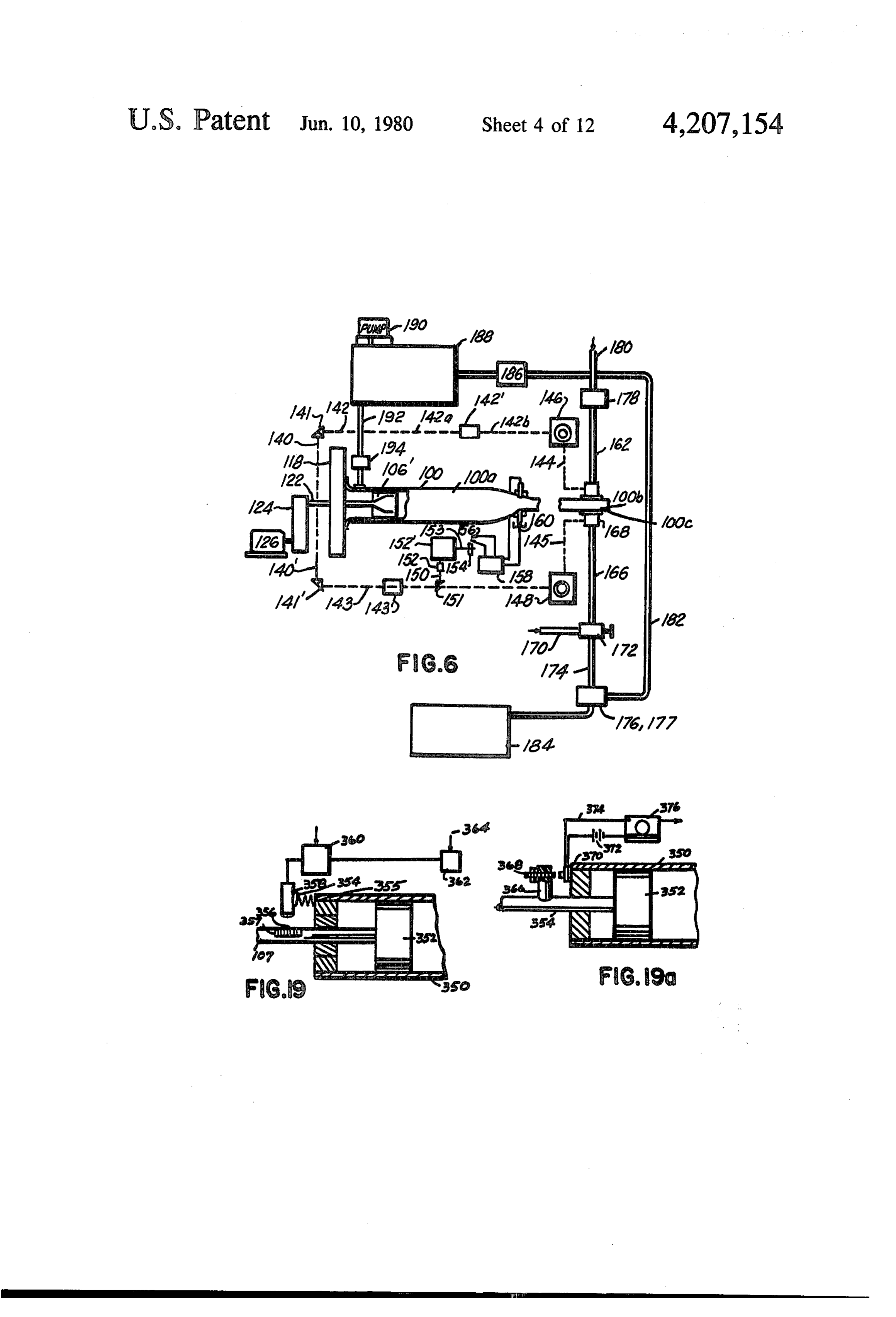
liquid and the ends of said tubes may be projected just Additional design features illustrated in FIGS. 3 to 5 above or below the surface of said liquid. include radial holes 122" provided through the cam disc The reaction tubes 100a to 100k are shown each sup- 10 118 from near the shaft mount or bearing near the cen ported at one end by a plate or frame 104 which is ter of said cam wheel for conducting a lubricating oil to bolted to the floor or frame 105 on brackets 104 and at the channel 120 for improving the operation of urging the other end by a second plate 130 supported by brack the cam rod or wheel 116 engaged therein and reducing ets 109. Details of the mounting of the head end 100' of wear on the walls of said sinusoidal cam channel. Oil each tube are illustrated in the cross-sectional view, 15 may be pumped through the shaft 122 and thence FIG. 3 which shows a flare 102 welded to the end of through multiple ducts or passages 122 provided in the said tube 100 which is bolted to the vertical plate 104, disc 118 or through tubing secured to the disc. In FIG. there being a hole 111 in the plate in line with the longi 5, a fluid line 112 is shown terminating at the head end tudinal axis of each reaction tube through which the of the chamber. Said line may be used to provide lubri piston rod 107 passes. In FIG. 5, the hole 111 is fitted 20 cant for lubricating the piston and cylinder. A similar with a slide bearing 112 for guiding the piston rod in line may be used to introduce a driver or working fluid axial movement therein. A large disc 118 is provided as to the chamber 101 (12c) by introducing it into the a cam unit for driving the pistons 106 of all reaction volume 100c' between the bottom of the piston 106 and tubes as said disc 118 rotates. The disc, preferably made the cover plate 104 whereafter said fluid may be intro of metal, is mounted on a shaft 122 which is supported 25 duced into the chamber 101 downstream of the piston on end bearings 123 and 125 secured to the floor or by valving in said piston to be described. frame 105. The shaft 122 is driven through a reduction FIG. 6 illustrates schematically, apparatus for con gear drive unit 124 by a motor,126. The periphery of the trolling the aforedescribed wave generating means disc 118 is a cylindrical surface 118' having a cam way whereby timing of such functions as fluid injection, provided therein in the form of a closed loop channel 30 reaction product exhausting, spark generation, etc. is 120 of a smooth wave-like contour preferably in the effected by directly coupling timing means to a drive form of a flat sinusoidal curve, as illustrated. In FIG. 5, shaft utilized to drive said piston 106. In FIG. 6, an a ring 119 is fitted over and secured to the periphery of adjustable speed, constant speed motor 126 drives shaft the wheel and partly closes off the sinusoidal channel 122 through gear box 124. Coupled to shaft 122 is the 120. An arm rod 114 formed on or welded to the end of 35 can wheel 118 of FIG. 3 which, as it rotates, causes the piston rod 107 projects into the channel 120. A piston 106 to oscillate back and forth a predetermined roller bearing or bearing supported wheel 116 is rota stroke in tube 100. The piston 106" is assumed to be the tionally mounted on the rod or shaft 114 and rides on valving type illustrated in FIG. 14 or 15 and a chamber one of the side walls of the groove 120 depending on 322 is provided in ducting 100 for holding a quantity of which part of the closed loop curve of said groove is 40 fluid to be injected through 106 in the expansion or opposite said piston. As the disc 118 rotates on its shaft, return stroke of said piston. It is noted that one or more the cam shaped channel 120 will trace a reciprocating of the valving or sparking means to be described may be path in any plane passing through and containing the modified or eliminated as described, from the apparatus axis of the shaft of the disc. The wheel 116 will thus be of FIG. 6 depending on the desired mode of operation carried in an oscillating motion in the groove 120 as the 45 thereof.
disc rotates and will urge the piston 106 to oscillate a Control of timing of the opening and closing of the multiple number of times each time said disc rotates inlet and exhaust valves 164 and 168 to working cham depending on the number of loops to the curved chan ber 100bis effected through shafting geared to the shaft nel. If there are 8 cycles or loops to the channel 120 on the camperiphery, then each piston 106 coupled thereto 50 a122second or gear drive 124. A shaft 140 is geared to shaft 122, shaft 142 is coupled to 140 via gears 141. This as illustrated will oscillate 8 times for each rotation of shaft 142 extends to a variably adjustable speed drive said cam disc 118. If the cam disc 118 is driven at 1,000 146, such as a V-belt device, having an output shaft 144 r.p.m. then each piston will oscillate 8,000 times per extending to an inlet valve 164 which is preferably the minute. type illustrated in FIGS. 7 and 8. Thus as main drive Connected to the ends of each reaction tube is a cir- 55 shaft 122 rotates, the valve drive shaft 144 rotates, and cular duct 128 which communicates with each tube. A can be made adjustable by adjusting drive 146 to rotate fluid pumped through said duct is thus subjected to once, twice or any desired number of times while the shock waves at the points in its travel where each of the piston oscillates once. Shaft 122 may also be made to tube ends 101 connects thereto. A stream length of fluid rotate once for any predetermined number of oscilla in circulating through duct 128 from inlet line 132 to 60 tions of said piston. The latter operation (i.e. one valve exhaust line 133 is thus subjected to the heat and pres rotation or operation per number of perturbances or sure
of shock waves of each of the shock tubes 100a to shock wave generations will permit the working fluid, In FIG. 5 the notation 112 refers to an inlet line to or solid in 100b, to be subjected to shock waves for a prolonged period of time.
chamber 101' for the admission of a fluid thereto and/or 65 Once the variable drive 146 has been set and locked at a lubricating fluid for lubricating the piston 109 in its a predetermined value, phasing of the rotation of valve traverse motion in the tube section 100'. 122" refers to a with the motion of piston 106 may be effected by use of hole or line provided in or attached to the flywheel 118 a non-slip friction clutch between any segments of said
Page 21
take off shafts or by an angularly adjustable shaft cou similar to 146 and 194 to a regulator or a valve for the pling in any shaft such as 142' in shaft 142, Angular valving of driver or working fluid or explosive fuel to adjustment or phasing of the operation of 164 with the the chamber 322. It is noted that the various valves of motion of the piston may be effected by the provision of FIG.6may be solenoid operated and controlled to open graduations or marks on said shafts 142a and 142b and 5 and close by means of electrical contactors such as 156 stationary alignment pointers adjacent to each. By man synchronized to close and open at a specific point(s) in ually rotating one shaft section relative to the other and the rotation of the shaft driving the piston 106". noting the position of the marker line on shaft relative to FIGS. 7 and 8 show details of a rotating valve utilized a stationary marker, then locking or coupling the shafts for the admission of fluid to the reaction chamber and 142 and 142b together at a predetermined position rela 10 /or reaction product removal from the reaction cham tive to shaft 122, the desired timing of the operation of ber described. The valve 204 may be coupled in an inlet 164 relative to the position of the piston 106 may be or exhaust line leading to or from the chamber 100b or effected. it may be fastened to the wall of the chamber 100a or In means similar to that just described, the rotary the end wall 100c of the reduced section 100b. In the exhaust valve 168 or any other valve used for the admis 15 latter position, in line with the central or longitudinal sion or exhausting of products from chamber 100b may axis of the shock tube 100, the valve 204 may be oper be coupled to the main drive and timed to operate in a ated so as to permit all or part of the shock wave gener predetermined synchronization with the motion of the ated in the closed tube to travel therethrough to another piston 106. chamber, to admit and/or exhaust gas from said cham Also illustrated in FIG. 6 are means for timing a spark 20 ber for predeterminedly affecting wave motion or the to be generated at or across the section 100b to occur at reaction, or for removing part of the products of reac a predetermined time in the wave generating cycle in tion therefrom.
accordance with the teachings of FIG. 2. A shaft 150 is The valve 204 has a body 204" made of a rectangular geared to shaft 143 which is coupled via gears 41' to block of metal having two passageways bored therein. shaft 140' geared to the main shaft 122. The shaft 150 25 A first bore 206 is provided through said block for extends to another shaft 153 via a coupling 152. The passing a fluid through said valve. A second passage coupling 152 like 142' is adjustable in angle so that shafts way 204 is provided perpendicular to hole 206. Plates 150 and 153 may be adjusted in relative angle to each 204a and 204b are secured in sealing engagement with other. A cam 154 on the output shafts 153 is adapted to the surfaces of the block 204' across which the hole 207 open and close a switch 156 or contactors which, when 30 is bored. A cylindrical gate 208, is slidably mounted in actuated, complete a circuit as illustrated and described the bore 207 on shaftpins 210 and 210'. A bore 209 the and cause a spark to jump across electrodes 160 and 16. diameter of the bore 206 is provided through cylinder by discharging condensers or energizing a spark 160 208 to align with said hole 206 when the cylinder 208 is and 16 by discharging condensers or energizing a mounted as shown. Thus rotation of the cylinder or rod spark-coil 158. Thus said spark may be made to occur at 35 208 alternately covers and opens the bore through the any time during a pressure cycle by varying the relative valve body 204. A gear 214 secured to the end of one of position of shaft segments 150 and 153 or by adjusting the shafts 210 is engaged by another gear 214 extending the angular position of the cam 54 on its shaft. A vari from a motor driven shaft 21 coupled to motor 22. able speed drive or changeable gear box 152" provided The shaft 211 may be the shaft of the motor driving in shaft 150 may be used to create more than one spark the piston 106 or may be coupled thereto. It may also be per cycle by stepping up the rotation of shaft 153 a coupled to the shaft of a motor synchronized in its oper desired degree. Stepping down said gear or shaft ratio ation to the rotation of the motor driving said piston so will provide one spark produced shock wave per num that the valve 204 may be operative to admit and/or ber of pressure wave generations caused by motion of remove fluid from the shock tube 100b predetermi the piston 106". 45 nately during each pressure cycle. The motor driving Further details of the apparatus of FIG. 6 include an shaft 210 may also be a stepping motor operative to inlet duct 62 to valve 164 and an adjustable valve 178 intermittently open and close said valve by rotating it 90 for adjusting the amount of flow from a pressurized degrees at a time. The rotational positioning of the reservoir (not shown) to chamber 100b, a second adjust cylinder 208 may also be made to occur once during able valve 72 for regulating the degree of suction in 50 every predetermined number of pressure wave cycles exhaust line 166, a vacuum pump 76 connected to 166 or at a predetermined time interval, after the starting of through valve 172. said reaction apparatus after a known reaction has oc If the mode of operation of the apparatus of FIG. 6 curred so as to remove reaction products from the includes the use of a neutral driver fluid such as helium shock tube and/or add new fluid thereto. Synchroniza in which said shock waves are generated, and said in 55 tion of the motor 212 driving the valve gate 208 with jected working fluid is a gas whereby a fluid gas or the rotation of the motor driving the piston 106 may be vapor is removed during operation, then some of said effected by providing both said motors as synchronous driver gas will also be removed and will have to be motors operated by a common alternating current replaced. Also illustrated in FIG. 1 is a pressurized power line. By providing an adjustable phase shifter reservoir 88 of said driver fluid ducted through a line between said power line and one of said motors any 192 to the chamber 322 before the piston 106 through adjustable operation of one of said motors with the an adjustable valve 194. If driver fluid is passed out with other motor may be effected so as to predetermine the the products of reaction, the total exhaust products may instants or the opening and closing of valve 204 relative be passed through a separator 177 prior to passage to a to the transient pressure cycle in the shock tube 100. By storage tank 184 wherein the driver fluid is separated 65 controlling the pressure upstream of the valve 204 as therefrom it may be further processed and returned or well as the concentration of gas, gases or other fluids recycled through the reservoir 188 via ducting 132. In passed therethrough, optimum operating parameters FIG. 6, the numeral 48 refers to a variable speed driver may be attained.
Page 22
FIG. 9 shows details of a fluid pressure operated the pressure drops seating section 231 against surface valve operative for the admittance of a working or 222 and closing off 240.
driving fluid to any of the described reaction apparatus The spring seat member 234 is secured to the insert regions. The valve 220 is opened by the fluid to be through a yoke 238 extending across the insert 224. The admitted at a predetermined pressure and closed by the fluid passed through the valve 221 flows through open action of a spring. It may be applied where a fluid under ings 236 between the yoke mount 238 and the insert intermittent pressure is available, or may utilize the wall 224.
fluctuations in the reaction chamber pressures caused If the pressure against 230 is constant but just enough by the internal wave motion so as to admit fluid thereto to open the valve, the increase in pressure within 16c at a specific instant in a wave cycle. 10 during the operating, cycle may be used to close the The valve 220 comprises a body 222 including an valve and the piston motion will automatically be syn assembly of a cap member 223, a plug 224 and a base chronized to the pressure cycle.
ring 225. The latter 224 has holes therein for fluid flow Another type of inlet valve is illustrated in FIG. 10' to the interior or the reaction chamber from holes 228 and comprises in its simplest form, a flat spring 242 when a piston member 230 compresses a spring 232 and 15 cantilever mounted over an opening 243 in the wall 244 moves thereagainst unseating a shelf section 231 which of duct 10 with a fluid inlet line 245 connected to the normally covers the holes 228 which communicate with duct at the opening. This is a well-known reed valve the inlet line 226. Thus fluid in said feed line 226 forces and the pressure required to open it depends on its di open said valve when the pressure differential across mensions and spring characteristics when mounted. the piston 230 overcomes the force of the spring 232 20 Sufficient pressure within the inlet line 245 will move and said fluid is delivered to the chamber. reed off its closed seating position permitting fluid to The FIG. O', the line 226 of FIG. 9 contains a driver enter chamber. The fluid may be pressure pulsed against fluid which, when its pressure becomes great enough, 242 or provided at constant pressure with the internal pushes piston 230 against spring 232 unseating shelf 231 pressure variations accounting for opening and closing and permitting an inlet hole 240 to communicate said 25 of the valve.
chamber with a second inlet line 241 containing a fluid FIG. 11 shows details of a typical valve for the admis desired to be flowed into said chamber 16c. The driver sion of fuel or driver gas to the smoothly contoured fluid pressure may be obtained from a source of control chamber 251 of any of the wave generating apparatus lable or intermittent pressure which is synchronized in described, or for exhausting the resulting products of pressure variation to the variations in pressure in the 30 reaction therefrom. A valve head 250 is integrally duct 16. The line 226 may also be a bleed line connected formed on the end of a stem 252 which is slidably sup to another part of the reaction chamber or shock tube at ported in a bearing 253 secured to the walls 246 of an a location so as to provide the desired valve opening at enclosed cup-shaped housing 247. A compression coil the desired time in a cycle. spring 257, engaged between the top 258 of housing, FIGS. 10 to 18 show details of automatically oper 35 engages a shelf 254 integrally formed on the stem 252, ated valves for the admission or injection of fluids into and urges the head 250 against the walls of a tapered the shock tube chambers provided herein and/or the hole H in the chamber wall 251. The face 250' of the automatic removal of reaction products therefrom. valve head 250 has a radius of curvature equal to the In FIG. 10, a valve 221 is provided which is opened inside radius of the chamber wall 251 so that when said for permitting flow of a fluid therethrough from an inlet 40 valve is seated flush with said wall 251, the latter will be line 227 by pressure bled from one of the chambers of free of irregularities thereby providing a smooth inte the shock tube illustrated. In the embodiment of FIG. rior surface for optimum efficiency during the genera 10, fluid, under pressure, is preferably bled from near tion of the shock wave phenomenon in the duct. A the head-end of chamber section 16 through line 227 maximum efficiency is attained.
which fluid reacts on one face 230 of a piston 231 forc 45 The valve may be opened by one of several means ing it against a spring 232 which operates to normally including a cam rotated by a shaft gear or synchronized keep said piston flush against a face 222 of the valve, to the shaft driving the piston 20 creating the wave preventing flow from inlet line 241, thereby opening motion. Another method of synchronizing the opera said valve. Ports 240 extending from the inlet line com tion of valve 245 to the wave motion is to open said municate with the inter-volume 16c of the duct 16 when SO valve by a pull-solenoid which is coupled to stem 252 the shelf 231 of the shaped piston or plunger 231 moves and mounted on the top of chamber 246. The solenoid from its seat against surface 222. The coil spring 232, is may be actuated by a photo-relay, pressure switch or compressively engaged in a hole 232 provided partly limit switch in circuit with a power supply and said through the piston section 231 and is held at its other solenoid, which is energized at a point in the piston end by a rod extension 237 of a mount 238 which 55 travel as described.
threads into the valve body as illustrated. The numeral 255 refers to a fluid inlet line communi It it is desired to introduce a working or driver fluid cating through hole 256 with the chamber 256 by use of to the chamber 16c by the pressure of said fluid alone fitting secured to hole in wall 246 which holds fluid to rather than by the bleed actuated means illustrated, said be admitted through said valve when 250 is lifted off its fluid may be provided under a constant or pulsating seat.
pressurization from a pump through the line 227, at a FIGS. 12 and 13 are sectional views showing details sufficient pressure to move said piston 231 against the of a multiple inlet and outlet valving device 260 applica closing action of the spring 232 whereupon a by-pass ble to apparatus of the type described. A body or hous duct (shown as a pair of dotted lines communicating ing 262 is provided to which are secured multiple ducts between said inlet duct 227 and the chamber 16c when 65 264 to 268. The ends of the housing 262 are flared per 231' is unseated and normally covered by the latter) is mitting the device to be bolted to a duct 276 which may used to provide fluid from 227 to chamber 16c. If the be the end of a tube such as the section 16 of FIG. 1 or line 227 is pressure pulsed, the piston will return when tube 48 of FIG. 2. The duct 276 may also be an inlet
Page 23
pipe for admitting a fluid or fluids to the interior of the reaction apparatus of the type described. In FIG. 14 a fitting 260. Secured to the housing 262 are shown three piston 290 which may be similar in operation to piston tubes 264, 266 and 268 of essentially the same diameter, 20 of FIG. 1, may operate in the working zone of FIG. the axes of which are preferably in the same plane and 2 as does 20 or may be oscillated on the end of shaft 22 are essentially perpendicular to the axis of the duct 278. 5 in any of the other illustrated fluid inlet or exhaust lines. The tubes 264 to 268 communicate with the interior of The center of piston 290 has a longitudinal bore 296 the valve 260 through holes 280 in the wall with which which extends partly through the shaft 294 to a point they are aligned, when three holes 281 of a walled cylin where a radial bore 297 communicates 296 with the der 272 are aligned with the holes 280 in the body 262. exterior of said shaft. An injection nozzle 292 is prefera The cylinder 262 is open at one end 263 and closed at 10 bly threaded and adapted to be secured in the counter the other by a plate 284 welded to its other end. Cen bored and threaded end of the bore, and is shown flush trally secured to or formed integrally with the endplate with the face of the piston.
284 is a shaft 286 which is rotationally mounted in a A bearing assembly 298 provides means for commu bearing and shaft seal 288 secured to a plate 289 cover nicating a fluid with the bore 296 as the piston 290 ing the end of casing 262. The shaft 286 may be stepped 15 oscillates relative thereto in a part of the reaction cham or rotated by a solenoid mechanism or motor at any ber or inlet line. The bearing 298 has a volume adjacent predetermined rate or speed to alternately permit the the radial bore of sufficient longitudinal extension to tubes 264 to 268 to communicate with the interior of the always communicate with said bore regardless of the cylinder 272. Thus when the cylinder 272 is aligned stroke position of said piston, although it may be limited with its holes 281 aligned with the holes 280 in the 20 in length and positioned only to communicate therewith casing, a smooth and uninterrupted flow of fluid from at a point in said stroke when fluid delivery is desired. tubes 264 to the inner volume 282 of cylinder 272 if all The volume 300 which is formed by undercutting or holes 280, 281 and the bore of said tubes 264 to 268 are providing a cavity in the inside surface of said bearing, the same diameter. Notations 287 and 287s refer to ball communicated with an inlet tube 301 through a hole 302 bearings and seals secured between the outer wall of 272 25 in said bearing wall. Thus fluid introduced into volume and the inner wall of 262 to facilitate rotation of 262 and 300 through tube 301 flows through bore 296 and to the seal of the interior of said fixture or valve. nozzle 292 through which it may be injected into the Another line or pipe 270 of smaller diameter than the volume beyond the piston. The numerals 304 and 304 others is shown secured to the casing 262 in an angular refer to sliding shaft seals supported by the housing 298 position whereby it will communicate with the volume 30 and adapted to engage the shaft 294 and seal off the 282 when the other ducts 264 to 268 are shut off from chamber 300 as shaft 294 oscillates. said interior as a result of the rotation of the cylinder FIGS. 15 and 16 show details of a modified reaction 272. chamber design including a modification in the design The device of FIGS. 12 and 13 may be utilized with of a wall or surface positioned in the path of intermit the described apparatus in one of several manners: 35 tently appearing shock waves and shaped to more effi (a) Said valve 260 may be fitted on the end section ciently utilize said waves in reaction kinetics of the type 278 of a shock tube as illustrated. The three tubes 264 to described involving fluids. When a shock wave travels 268 may be used to conduct three fluids of different into a container, duct or volume of increasing cross chemical composition to the chamber 282 to be mixed section it increases in intensity. By providing the end and subjected to shock waves generated in 278 and wall 332 of a shock duct 330 or chamber wall with reflected off the back plate. multiple indentations 334 of decreasing cross section (b) The three tubes 264 to 268 may also be the end with depth, the pressure and temperature effects on a sections of shock tubes utilizing the same or different fluid in said indentations will be increased or amplified, fluids as the tube 278. The fourth duct 270 may be used due to the facts that the shock waves are increased in to inject a working fluid into the chamber 282 and/or 45 value after they enter said volumes 334 and the fluid is remove products therefrom during or at the end of confined from lateral flow to a greater degree than if shock wave generation therein. said indentations were not provided. The efficiency of (c) If shock waves are produced in the three tubes certain reactions will thus be improved. 264, 266 and 268 as well as the main shock tube 278 to In FIGS. 15 and 16, the relatively heavy end-wall which they are coupled by means of the valve, the valve 50 section 332 is provided with a series of parallelly ex may be utilized to close off the chamber 282 to the tending V-shaped channels 334 through which a liquid chambers 264 to 268 while a fluid to be worked on is or other fluid is flowed from an inlet duct 336 at one injected through 270, or the three tubes 264, 266 and side of the chamber 330 to a removal duct 338 at the 268 may be used to introduce quantities of different other. It is assumed that the supply reservoir 336 is fluids simultaneously into zone 282 while 270 may be an 55 pressurized or provided with a pump (not shown) and exhaust line for the reaction products. Mor valve which may intermittently or continuously (d) The valve 260 may be used to close off two of the flow fluid through the V-channels 334 in 332. For exam three ducts 264 to 268 while the third is open to 282 ple, said fluid 337 may be filled to a specific height in thereby permitting a single shock wave to collapse on each channel 334 by influx through the openings 335 in the fluid at a time and, at the same time, permitting new the sidewall 332', thence subjected to a predetermined waves to be generated in the other two tubes which are number of shock waves until a specified reaction has closed off until a single opening 281 in 272 passes their taken place and thereafter removed from said channels respective port. If resonance is employed in 264 to 268 during the operation of the shock tube or after the wave to create shock waves, this will permit any disruptive generating means has been stopped.
effects caused by the opening of the valve to be cor 65 The channels 334 may be other than wedge-shaped in rected. cross section. Said indentations 334 may be replaced by FIG. 14 shows still another variation in the described cone, semi-spherical or other shaped cavities which means for admitting or valving a fluid to the interior of may be partially filled and emptied by gravity means
Page 24
(by tipping or dumping the tube 330) or through ducts FIG. 19 shows details of another method of valve and leading to an interconnecting said cavities through the piston timing or synchronization control which utilizes block or wall 332 with supply and drainage or suction a photoelectric cell or the like for scanning marks on the systems. The numeral 339 refers to holes in the wall 332 piston shaft 107 to initiate valve actuation as well as through which products of reaction are removed by effect other control functions such as spark generation. gravity or suction means to ducting 340'. Numeral 340 Notation 358 refers to a photoelectric relay including a refers to a feed line for supplying fluid to reservoir or photoelectric cell, amplifier and associated optical inlet duct 336. means including a slit permitting the scanning unit to Several methods of controlling the valving and other line scan locating lines. The unit 358 is mounted on a mentioned intermittent operating devices are illustrated 10 bracket 354, supported by shock absorbers 355 secured
In FIG. 17, the piston 20 oscillating in the primary just to the wall 350 of the reaction chamber and positioned above the end of piston shaft 107. A grating or grid chamber 12 is driven by a motor through a cam 118. 356 of black and white serves as locating marks which Affixed to the shaft 22 of piston 20 is an arm 115 which are painted, printed or otherwise provided on said shaft extends outwardly therefrom. Secured to the arm 115 is 15 or on a sheet 357 of rigid material such as glass which is an elongated rod 343, which moves in a slide bearing secured to said shaft 107 in a position whereby said lines 343 as the piston 20 moves back and forth. A pin 344a will be individually scanned by the optical head 359 or secured the other end of rod 343, rides in a slot in the slit associated with the photocell of the relay 358. De end of a crank arm 344 which is pivotally mounted on pending on the stroke of the piston 352, the spacing of the casing of a valve 40'. When the crank is urged to 20 the lines on the grid 356 will be a function of the degree pivot by the action of arm 343, rod 343 operates to open of precision required in timing the operation of the and close the valve 40' which connects a line 28' extend wave-generating apparatus. FIG. 19' is a view in a plane ing from a pressurized source of fluid to be injected into perpendicular the chamber 20 and said chamber. Thus, at a predeter fraction gratingtoorthehigh shaft 107 and shows use of a dif mined location during the stroke of the piston 20, fluid 25 tion and timing. FIG. 19' resolution shows a grid for shaft loca grating mounted on a will be injected into chamber 20. The coupling between plate 357 which is a sheet of glass secured to a flat the shaft extension 115 and rod 343 is adjustable so that section of shaft 107 and overhangs said shaft. The the timing of the operation of valve 40' may be adjusted lines on 357" may be in the order of 500 to 5,000 linesgrid per to attain an optimum mode of operation. A collar 115 is inch. To photoelectrically detect these lines, a slit light welded to the end of rod 115 to slidably engage said rod 30 source 358' is also mounted on shock absorbers which 343. The end 343b of the rod 343 is threaded. By adjust are secured to the duct 350 or its support. The light ing a pair of locking nuts 343c and 343d, the location of source 360 is aligned to pass a thin line of light through the piston 20 at which valve 40' opens and the degree of one or more of the spacings between grid lines 357 valve opening may thus be adjusted.
FIG. 18 shows details of a piston operated valving 35 which results in a pulse signal train being generated as the piston moves, which pulse train is passed to the device for use in the apparatus described to admit and adjustable predetermining counter 361 operative to emit /or remove fluid material to the described shock tubes, a signal upon the receipt of a predetermined number of their main chambers, working zones and/or described pulses from relay 358. The pulse output of counter 361 sub-chambers connected thereto. The valving piston may be used to energize one or more devices 362 such 350 of FIG. 18 may be used, for example, as the work as solenoids, solenoids for the described valves, or ing piston 20 of FIG. 1 or as the working chamber end switches controlling spark discharge. It is noted that the wall or valve 48 shown in FIG. 2. The piston 350 may grid on sheet 357 may be replaced by one or more marks also be used in any of the inlet or exhaust lines 28, 30, 36 or lines at predetermined points provided along the or 38 of FIG. to valve fluid to one or more of the length of piston rod 107 at locations where it is required shock tube zones or remove reaction products there 45 to effect one of the described cycle actions for predeter from. As such, the piston may be oscillated after a pre mined operation without need for an adjustable control determined number of motions of the main piston 20 to ler such as a presettable predetermining counter. introduce and/or remove a predetermined amount of Another means for timing the occurrence of the de fluid necessary to sustain the reaction and/or continue scribed the process. The piston of FIG. 18 may also be oscil 50 mittent auxiliary functions in the operation of an inter shock tube as described, is illustrated in FIG.
lated to open and close once during each pressure cycle 19a and may be employed to control such described (i.e. once for each cycle of motion of the main piston or actions each pressure pulse in the shock tube resulting in the valves toas admit the opening and closing of inlet and exhaust or remove fluid relative to any of the formation or amplification of a shock wave in the work regions of the herein described apparatus, the regulation ing section). 55
The piston-valve 350' of FIG. 18 comprises a cylin of flow of a fluid relative to the reaction chamber, the control of one or more of the described motors, or the drical piston head 350 having one or more piston rings timing of wave generating spark discharges to augment 351 assembled therewith and slidably engaged in the fluid flow or other operations which need be synchro tube 12. The interior of the piston 350 has a bore 352 in nized to the oscillating wave motion in the duct. In which a sub-piston 353 is slidably engaged and is prefer FIG. 19a an oscillating piston 352 is provided in a duct ably sealed around its peripheral surface with rings 354. 350 arranged, for example, in apparatus such as illus A shaft 355 of smaller diameter is integrally formed with the sub-piston 353 and is engaged in a slide bearing tratedAn in either FIG. 1 or FIG. 2 or elsewhere herein.
actuator comprising a rigid rod 366 is secured to the 112 secured in tube 12 by a plate 356 which engages and piston shaft 354 and is operative to close the contacts of is held against the inside wall of tube 12. The shaft 355 65 a limit switch 370 when the piston 352 is at a predeter may be driven by various means including a cam disc 118 if piston 350 is the main piston of the apparatus or a mined point in its travel. Said switch 370 is mounted on the end wall of duct 350. The switch 370 is provided in crank or other mechanism. series circuit with an electrical power supply 372 and an
Page 25
adjustable time delay relay 376 so that switch 370 may 380 is mounted with the end portion 382 thereof extend be closed at a selected point in the oscillating gas dy ing into a second duct or container 384 in which is namics cycle occurring in the duct 350. When switch contained a liquid 386 completely or partially filling 370 is actuated by contact with actuator 368, a pulse is said container. Arrow notations 387 indicate the process transmitted to delay relay 376. The output 377 of delay liquid as being in motion past the end of the duct 382 relay 376 may then be passed directly to device 362 to which end is opened and projects below the surface of be controlled thereby or to one or more of the men the liquid 386. The process liquid may also be stationary tioned valve solenoids or servos. The actuator arm 368 or adapted to be intermittently flowed past the open end is shown longitudinally adjustable on piston rod 366 383 of duct 382 and removed from container 384 after a permitting switch 370 to be adjustably closed. 10 predetermined reaction thereon has taken place as the FIG. 19.c shows still another means for effecting tim result of shock waves generated in 382 which intersect ing and control in the operation of valves and the gener said liquid. The pressure effects of the intermittently ation of sparks in apparatus to occur at a precise instant produced shock waves which intersect the liquid in during each pressure or shock wave cycle occurring in tube section 382, provide a pumping action which first one of the described shock tubes. In FIG. 19c timing is 15 forces some liquid out of said tube section 382 and dur controlled and effected by the wave generated transient ing rarefaction draws it back into duct 382. Liquid from pressure. 384 is thus at least partly continuously replaced in tube A pressure sensitive gage 378 is mounted on the wall 382 and if flow is provided by providing a pressure 350 of the shock duct 12 and recessed or shaped so as to differential along the duct 384 using a pump upstream offer minimum resistance to wave and fluid flow. A 20 or downstream of the section illustrated, a substantial gage such as an electrical condenser transient pressure amount of the process liquid will be subjected to the gage is employed which provides a change in output temperature and pressure effects of said waves. The signal when the gas pressure on the face 378 of its probe apparatus of FIG. 20 may also be operated in which the or transducer element varies. The electrical output 378" surface 386L of the liquid is always below the end of of the gage 378 is connected to an adjustable relay 379 25 382 thus permitting interaction of the gas above the which may be adjusted to provide an output signal liquid surface and admitted through inlet 388, with the when the signal from gage 378 reaches a predetermined liquid in container 384. Other modes of operation in voltage. The voltage at which 379 produces an output clude completely filling duct 384 or partially filling it to signal may be adjusted to produce a control output a degree such that the liquid will never be driven out therefrom when a shock wave appears at and/or passes 30 the end of section 383.
said gage. Notations 380 and 381 refer to amplifiers in FIG. 21 is a schematic diagram of apparatus for the output of said pressure gage. The pulse output of changing gage 378 is then passed to a variable delay line 382 of liquids the chemical and/or physical characteristics which may be adjusted to provide an output signal at a utilizing wavesuspensions
generating or organisms in liquids by apparatus of the type de predetermined time in the cycle which signal may be 35 scribed. The apparatus illustrated, includes means for used for energizing a valve, solenoid or other servo for creating one or more sparks in the shock tube such as by effecting such reactions automatically and in accor operating a servo motor or a solenoid actuated switch dance with a predetermined control sequence such that predetermined amounts of material may be predetermi for discharging one or more condenser banks, or for nately processed. In FIG. 21, a reaction chamber 392 is effecting any control or servo action associated with the provided having walls of sufficient strength and suffi transient pressure process. By adjusting the delay line, ciently supported to withstand the output signal therefrom may occur at any time inter applied thereto during operation.theProtrudingforces and shocks into and val in the cycle due to the fact that the input thereto is communicating with the interior 393 of the chamber a function of the pressure variation and wave motion in 392 is an open ended shock tube 390 of the type de the apparatus. The output of delay line 382 may be 45 scribed herein. The duct 390 is shown welded to the top passed over multiple circuits to one or more devices wall 396 of the chamber 392 in a manner to effect a fluid such as a servo control or solenoid 384 for operating a first of the illustrated servos, or solenoid 386 for operat seal the therebetween. A bracket 398 supports duct 390 on cover. The top wall 396 is preferably secured in ing a second of the illustrated servos, to a delay-line 388 sealing engagement to the bottom wall 394 of the vessel and then to a second servo or solenoid 388 for operating 50 392 so that fluid contained another of the illustrated valves or sparking devices 390 forced out during operation.inAnsaidinlet vessel will not be valve 402 is se and to other servos or solenoids.
Transducers other than a pressure sensitive gage and cured to the top wall 396 of the vessel 392 for the admis relay may also be used to trigger or control servo opera sion of one or more liquids and/or gases thereto from an tions which are thus synchronized to the pressure and 55 inlet line or lines 404. An exhaust tube 416 is welded to wave motion in the intermittently operated wave gener the vessel near the bottom portion of a sidewall. A ating apparatus described. For example, a photoelectric solenoid valve 418 and pump (not shown) are used to cell, scanning a light source or beam directed through a effect the removal of liquid from the chamber, or grav predetermined section of the ductor tube of FIG. 2 may ity may be utilized to drawn off the reaction products. be employed to detect the passage of an intense shock The vessel 392 is filled to a selected level with a liq wave therein. For weaker shock detection, a photomul pumped uid, liquids or solid-liquid suspensions. If the liquid is tiplier tube device which scans the field of a Schlerein through the inlet valve 402 to completely fill optical system may be used to detect the presence of a the chamber, then the liquid in the tube 390 will always shock wave in the shock tube by variations in the re be subjected to shock waves without being substantially ceived light as the shock wave passes. 65 displaced. If the resonant wave apparatus of FIG. 1 is Process apparatus utilizing such devices as the wave utilized as the tube 390, then said liquid will provide generating duct of FIG. 1 or 2 or the like is illustrated means whereby shock waves will react on and reflect in FIGS. 20 and 21. In FIG. 20, a resonating wave tube off said liquid and thereafter propogate substantially in
Page 26
a manner similar to the waves propogated in a closed tate securing the ducts 450-460 thereto. In FIG. 24, the end tube. tube 440 has a necked down section 442 which is cou For automatic operation of the apparatus of FIG. 21, pled to a tubular section 446 of reduced diameter which a predetermined amount of liquid or flowable solid may correspond in function to section 16 of FIGS. 1 material is admitted to the chamber 392 to partly or and 2. The tubes 450 to 460 may be shock tubes adapted completely fill said chamber. This may be effected pre to simultaneously transmit shock waves to the main determinately by operating the inlet valve while auto chamber 440 to collapse on a fluid injected therein matically controlling the operation of the piston and through a nozzle or inlet valve 462 and, like the appara spark generating means for creating shock waves in tus of FIGS. 22 and 23, serve to create chemical and/or duct 390. After a predetermined operating time in 10 physical changes in said injected fluid prior to its entry which shock waves are reflected off and/or partly ab into the section 446. Notation 448 refers to a piston sorbed by said liquid to effect a predetermined chamical operating in section 446 for augmenting wave effects in or physical reaction, the exhaust or drain valve 417 is the duct or to a valve. The tubes 450 to 460 may also be opened and reaction products are removed by the ex utilized for admitting a plurality of different fluids into haust pump 418 and the cycle is repeated. 15 the reaction chamber 440 by valving means or by reso A multi-circuit self-recycling timer 412 is provided in nant wave action involving flow in all said tubes. the apparatus of FIG. 21 to operate each of the men FIGS. 25 and 25 show a spherical reaction chamber tioned valve solenoids and servo-motors for predeter 464 into which multiple shock waves are directed, ei mined time intervals to effect the above described ac ther one after the other in rapid succession or simulta tions in sequence. The timer 412 control circuits include 20 neously from multiple shock tubes 477 to 480 to spheri a start control for the motor driving the piston in tube cal chamber. Such an apparatus may be employed for 390, a stop control for the servo or solenoid operating reacting on a single fluid or mixture of fluids previously each valve and a start and stop control for each men disposed in said spherical chamber 464 or predetermi tioned pump motor. When actuated by signals from nately injected with respect to the appearance of shock timer 412, each of these servo devices operate the 25 waves therein.
valves and other devices or by known means. Notation The reaction chamber 464 consists of an assembly of 400 refers to a motor driving paddles 408 in vessel 392 semi-spherical shell sections 466 and 468 having flanges for circulating liquid therein during a reaction cycle. 470 and 472 circumscribing the edge of each and assem FIGS. 22 and 23 show apparatus which employs bled face to face so as to seal said chamber to define an shock tubes to heat and/or compress a fluid moving 30 enclosed spherical reaction volume or zone 465 contain through a duct 430 to create a reaction therein. Nota ing or terminating the illustrated piping connected tion 431 refers to a working section of a duct or pipe 430 thereto for the admission and removal of working fluid through which a liquid, gas or vapor is flowing. In FIG. and products of reaction.
23 a cross sectional view of the duct at the working The chamber illustrated in FIG. 25 employs four section 431 is shown in three shock tubes 432, 434 and 35 shock tubes 477, 478,479 and 480 of the type described. 436 secured to duct 430 by welding. If the shock tubes These tubes may be any suitable design and operation 432 to 436 are mounted within their axes in a single and have their exhaust ends secured flush to the spheri plane (perpendicular to the longitudinal axis of 430, and cal surface 465 of wall of the chamber. If said four tubes are equi-spaced at 120 degrees about 430, and shock 477 to 480 are axially aligned and welded or otherwise waves are generated simultaneously in each and reach secured to the wall 464 of the sphere at 120 degrees to the chamber 431 simultaneously, then the effect will be each other, normal shock waves generated in each such that all three shock waves simultaneously enter which simultaneously enter said chamber will define duct 430 and react on a predetermined portion of the substantially an equilateral pyramidal configuration or fluid therein may be made to impart extremely high volume the inside of which decreases rapidly in volume pressures and temperatures to the fluid therein. If the 45 as said shock waves converge. The fluid within said fluid in 430 is a mixture of two or more liquids, gases, decreasing volume is thus not only rapidly compressed vapors or combinations of these fluids, the effect of the during the time interval said shock waves are present in high pressure and temperature of the simultaneously the chamber 465 but is heated to a high temperature, the appearing and collapsing shock waves may be utilized value of which will be a function of the intensity of the to effect one or more particular chemical reactions 50 shock waves, the dimension of the spherical volume and between said fluids. Depending on the intensity of the the characteristics of the fluid in the chamber. shock waves, the dimension of the duct 430 and the Several modes of operation of the reaction apparatus characteristics of the reaction fluid(s) in 430, high reac of FIGS. 25 and 25' as well as FIGS. 26-28 are noted tion temperature may be experienced by the fluid near and include:
the center of duct 430. By utilizing two pairs of aligned 55 (a) In a first mode, the reaction apparatus operates by and opposed shock tubes 432, the shock wave generated means of continuous injection of a single working fluid in each tube may be used to augment the rarefaction or mixture of fluids through a single injection nozzle effect in the opposite tube and generate a resonant wave 481 or nozzles and continuous removal of the products effect therein. of reaction via an exhaust duct 482 positioned across FIGS. 24 and 24 shown plural duct configurations chamber 464 from the inlet duct 481 or by means of a for wave generating apparatus. Six auxiliary ducts 450, plurality of outlets while shock waves of the same inten 452, 454, 456, 458 and 460 are shown with their open sity are generated in the shock tubes 477 to 480 at prede ends connected to a larger reaction chamber 440. The termined frequency and simultaneously enter the reac larger chamber 440 may be a shock tube in which shock tion zone 465.
waves are generated in accordance with the teachings 65 (b) A second mode of operation involves the intermit of FIGS. 1 and 2 or may merely serve to receive waves tent injection of predetermined quantities of a working from the auxiliary tubes connected thereto. Chamber fluid, or mixtures of fluids through a single inlet or 440 is shown modified with a hexagonal wall to facili injector 481 or through multiple inlets or the intermit
Page 27
tent injection of predetermined quantities of multiple characteristics of the fluid in the center section 485 and fluids such as liquids, gases, vapors, particles or combi the intensity of the shock waves generated therein, the nation of these materials injected in mixtures or through shock waves will partly reflect off each other and main separated inlets so as to mix within the chamber 464. tain the bi-directional wave motion in each half of sec Each of said predetermined amounts of fluids may be tion 485 and will provide a zone near the middle of injected into the zone 465 prior to the arrival of said section 485 the fluid of which will experience high shock waves at said chamber 464 or caused to flow by compression forces and high temperatures as said waves the action of the waves. The pressure increase in zone approach each other. Notation 490 refers to cooling 465 resulting from the arrival of the shock waves coils for circulating a coolant around the center of sec therein, and/or auxiliary suction pump means may be 10 tion 485 to help dissipate heat conducted through the provided to remove the products of reaction as de gas to the walls of said tube and, in certain situations scribed, with or without the use of an automatic valve. remove some of the heat of reaction. A fluid or fluids (c) In a third mode of operation the shock waves may be injected as described at a suitable time in each introduced into the chamber 464 may be generated by operating cycle and may be predeterminately removed means of apparatus of the type provided in FIGS. 1, 2 15 from the central section during each cycle or after a or 25. If the shock waves generated in all shock tubes predetermined plurality of cycles have caused a desired 477 to 480 are timed so as to appear simultaneously in the chamber region 465 a resonating transient wave reaction The to take place.
apparatus of FIG. 27 is similar to that of FIG. 26 phenomenon in each of the tubes 477 to 480 may be but is modified near the center of the reduced diameter sustained. Such resonant shock wave phenomena will 20 section 485' at which is provided a reaction chamber or be further augmented in another configuration in which vessel 491 communicating with the two tubes. The tubes 477 to 480 are positioned opposite and aligned vessel 491 is shown as a sphere although it may be any with each other across the chamber 464.
The tubes 477 to 480 may be welded or otherwise suitable shape, serves the function of the previously secured in sealing engagement with the chamber wall 25 described configuration.
FIG. 28 shows apparatus similar to FIG. 27 having 464". Notation 473 refers to a pressure seal such as a valves 492, 493, 494 and 495 respectively provided in metal O-ring or other flexible metal seal seated in a the shock channel 473" in one of the flange mating surfaces and exhaust linetube sections 16a and 16b, inlet line 488' and 489' which may be operated in any of the provided as a closed loop. Bolts or fasteners 474 are described manners to serve the various functions de used for clampingly engaging the flanges 470 and 472 30 scribed.
together to effect assembly of the two half shells 466 and 468. Brackets 475 and 476 are bolted to the flanges In FIG. 29 is shown a modification of the shaped 470 and 472 and are secured to upright supports 477 to shock tube reaction apparatus illustrated in FIGS. 1 and 478 which are rigidly affixed to a frame or base 479 for 2 operative to provide further wave augmenting effects holding the reaction apparatus in place. 35 beyond the primary chamber 12. Connected to the pri FIGS. 26 to 28 show a number of assembly configura mary chamber section 12 is a first reducing fitting or tions of pressure wave generating apparatus of the type section 14a of the type described which extends to a described involving a plurality of shock tubes which are first reduced diameter tube 16a which extends to a sec placed in endwise abutment and are interconnected so ond reducing section 14b extending to a further reduced that pressure or shock waves when predeterminately diameter tube 16b. The oscillating wave motion set up generated in each coact on a common fluid or fluids in section 12 by one of the means described induces a between the ends of said tubes. In FIG. 26 tubular shock shock wave of higher intensity in section 16a which in wave generator 482 is provided which comprises two of turn drives the fluid in section 16b in a manner so as to the shock tubes of FIG. 1 in endwise abutment and create a shock wave of still higher intensity therein. communicating with each other. The reaction appara- 45 FIGS. 30 and 31 illustrate wave generating apparatus tus comprises a first chamber 483 of enlarged diameter of the type described utilizing a so-called free piston having a reducing section 484 connected thereto ex internal combustion engine to generate pressure waves tending to a smaller diameter section 485 which con in tubes such as 10 of FIG. 1. FIG. 30 shows the free nects to an expanding section 486 of the same shape as piston apparatus as comprising a central engine block 484. A second chamber 487 connects to the other end of 50 520 containing a free piston assembly and auxiliary section 485. It is assumed that the wave generating apparatus having shock tubes 12a' and 12b' of the type means of FIG. 1 or 2 as well as valve means as described illustrated mounted aligned with said block at opposite is provided for each of the duct sections 483 and 487. ends thereof. If reduced diameter chambers 16a' and The center section 485 of the apparatus of FIG. 26 is 16b are provided and are respectively secured to the preferably less than the diameter of the end sections 55 tubes 12, shock waves of high intensity may be gener and approximately one sixth the total length of the tube ated in each by the operation of the engine which may 482. Connected to the center section 485 near or at its be used to perform any of the described process func middle, are an inlet duct 488 for admitting fluid thereto tions in any of the illustrated configurations or other and an exhaust duct 489 for removing fluid therefrom. combinations of the described apparatus components. By sparking electrodes or driving respective pistons in FIG. 31 is a section taken through the longitudinal each of said end sections 483 and 487 so that waves axis of the block 520 and shows components of the free generated in each travel simultaneously down the tubes piston engine which include a double headed piston towards each other and at the same rate a transient assembly 526 having a first piston 528 connected by a wave phenomenon is set up in each of the shock tube rigid rod 523 of smaller diameter to a second piston 530. sections 483 and 487 which causes respective shock 65 The pistons 528 and 530 are each operative to oscillate waves to be generated in the central reduced diameter in respective chambers 529 and 533 of block 520 while sections which will converge towards each other and the rod 532 slidably engages in a bore in a centrally meet at or near the center of the duct. Depending on the located block 538 separating the chambers 529 and 533.
Page 28
Fuel is admitted to the volumes 529 and 533 defined ment continuously through said tube while shock waves by each piston and the block 520 through respective are generated therein.
injection nozzles 544 and 546 at or near the end of the In FIG. 33, the end wall of the shock tube 570 is made compression stroke and may be ignited by conventional of a heavy block or plate of suitable metal or ceramic spark ignition means triggered by motion of said piston material which may be bolted or otherwise secured to assembly or by compression ignition means. Notation the flanged end section 571 of the tube 570. A fitting 574 542 refers to spark plugs or so-called glow plugs which is secured and centrally mounted on plate 572 which may be used to start or maintain ignition of the fuel may be a valve terminating a piping system for ducting during each cycle. The explosion action on the face 535 10 either intermittently or continuously a fluid such as a of each piston drives the assembly in one direction liquid, gas or particles through an opening 573 therein. whereby the volume containing the burning gas ex Other openings 578 and 589 which also terminate a fluid pands until exhaust ports are cleared by the piston per supply system are provided to supply the same or a mitting the hot expanding gases to escape through a different fluid to chamber 571. A single fluid or fluent manifold 522. The manifolds 522 and 524 (one or more 15 solid material or multiple materials may thus be injected for each combustion chamber) may also be shock tubes continuously or intermittently and synchronized to the utilized for process work of the type described or may generation of shock waves in chamber 571 to be di be connected to drive a gas turbine for operating the rected against and coat, abrade, chemically react with, illustrated or other auxiliary apparatus. The smooth etch, erode or shape the material of member 582 as it is bore 520' of each chamber extends to the ends of the positioned within, intermittently or continuously driven block 520 where shock tubes 12a' and 12b' are bolted 20 through said shock tube by any suitable drive means. thereto. Oscillation of the piston assembly thus alter Powered rollers, for example, may be used to friction nately creates a pressure wave in each duct which, if it ally engage opposite surfaces of member 582 and drive is not a shock wave, may be amplified to become one by it through chamber 571 at a predetermined speed. shaping the tube as illustrated in FIG. 1. If the member 582 is a circular rod, the gates 583 and FIG. 32 shows apparatus for dispensing a fluid such 25 584 are preferably conventional sliding shaft seals. If as a liquid as an atomized spray by means of high pres 582 is a sheet, plate or bar, said seals 583 and 584 may be sure or shock waves. Various atomizing functions may sliding seals of the desired shape employing one or more be performed at high efficiency utilizing the apparatus flexible pads with an opening therein shaped to engage of FIG. 32. Such functions as fuel and process mixing or 30 all the surfaces of the member 582. In another embodi atomization of liquids, the spraying of paints, carbeura ment, the end of the tube 570 may be made in two sec tion, fuel injection, etc. may be performed by apparatus tions adapted to separate and close in sealing engage of the type illustrated in FIG. 32 and the wave generat ment against member 582. The uppersection of reaction ing means provided therein. chamber or shock tube 570 may be separated from the The atomizing and mixing apparatus of FIG. 32 com 35 lower end as shown in FIG. 34 by use of a rack gear 596 prises a duct 560 in which intermittent shock waves are secured to the wall of 570', which may be raised and generated and travel towards an end of said duct which lowered by a motor driven pinion 598. The motor driv is closed off by a porous plug or plate 564 through ing pinion 598 may be operated to raise 570 sufficiently which a liquid or gas is made to flow. A smaller duct to permit the member 582 to be moved a sufficient 566 for the admission of said liquid terminates at a fitting degree to expose a new length of 582 to the shock 567 which is threaded or welded over a hole in the wall waves generated in 570' after the previous wave action 561 of duct 560 which is aligned with a hole 564 pro has been completed on the prior length. vided through porous plug 564. Shockwaves SW strike Various physical and chemical functions may be per the inside surface of plug after forcing fluid in the duct formed on member 582 as it remains in or is driven to flow through said plug 564 and cause the liquid in 45 through the shock tube 570, viz:
said plug to be forced through the pores or capillaries in (a) The surface of member 582 may be worked and said plug and eject as a spray from the other surface 565 /or heated by the multiple shock waves SW travelling thereof. The shock waves also transfer heat to said along tube 570 and intersecting said surface. Such ac porous plate thus heating said liquid and enhancing the tion may serve to heat the surface of member 582, heat atomizing action. 50 treating or working same.
The apparatus of FIG. 33 provides means for contin (b) The driving or working gas already in tube 570 uously processing an elongated solid member such as a may, by virtue of the effects of the shock waves gener bar, rod, sheet or tube by subjecting at least part of the ated in 570, react with the metal or material of member surface of said member to intermittent shock waves 582 to cure a coating applied to said surface or to chemi directed thereagainst while said member 582 is held or 55 cally react therewith to improve its characteristics. The driven through in said apparatus. The apparatus com member 582 may act as a catalyst in a chemical reaction prises a shock tube, a portion of which is shown in cross involving the fluid in duct 570.
section in FIG.33, for generating and directing multiple (c) Liquids or solids such as particles may be injected shock waves against an elongated solid member 582 into the chamber end 571 through nozzles 578 and 580 shown penetrating the end of tube 570 by passing during the shock wave generation to chemically react through two gates 583 and 584 which sealingly engage with member 582 and/or fluids disposed therein or the surface(s) of member 583. The gates 583 and 584 coated on the surface of member 582.
preferably comprise a pair of sealing pads or washers (d) Abrasive particles or surface working elements each having an opening of smaller area and shape than may be injected through inlet nozzles 578 to erode or the cross section of the member 582 and each secured in 65 work the surface of member 582.
a respective opening in the shock tube 570 and aligned (e) Combustible materials may be injected through across the walls thereof so that the member 582 will be nozzles 578 to further improve or predeterminately held in a sealing manner yet will be capable of move affect the action of the shock waves generated in 570.
Page 29
Notation 574 refers to a multiple valve mounted on plate 592a and the chamber 570'. The piston 593 with the end wall 572 of chamber 570 for controlling the articles or material thereon, may be raised or lowered a admission and/or removal of reaction products admit brief distance in intermittent and rapid manner by actua ted to chamber 57. tion of the lineal actuator 593 in a manner to cause In FIG.34, apparatus similar to that provided in FIG. articles thereon to bounce and/or shift position or atti 33 is applicable for effecting reaction kinetics involving tude. By such tumbling or bouncing action, the various shock waves operating on a surface or on materials or sides or surfaces of articles introduced into chamber articles disposed on said surface. Such positioning de 570' may be exposed to the direct effects of the pressure vice comprises, in FIG. 33 a rigid flight 586 of a con or shock waves generated within the chamber and if veyor. It may also comprise a belt such as a closed loop 10 articles or particles are provided or layers, those under belt of a belt conveyor. Notation 586' refers to a rigidly neath others will be vibrated to the surface with time supported table or bucking plate positioned in align thus providing means for exposing all of the material or ment with a movable shock tube 570' the end of which articles to the direct effects of the shock waves. may be abutted against member 586 with sufficient The apparatus of FIG. 35 may be operated with all of force to effect a fluid tight seal therewith. 15 the illustrated servo devices automatically controlled to The articles 582a or otherwise provided material to operate at predetermined time intervals in a predeter be subjected to the intermittent shock wave action are mined cycle by a multi-circuit cycle timer or other conveyed by device 570 to a position below the end of suitable automatic controller. The opposed doors 585a the retracted tube 570', whereafter said tube is brought and 585b are opened by respective air or hydraulic into abuttment with the upper surface of member 586 by 20 cylinders 586a and 586b which are shown mounted on the operation of motor 585" driving pinion gear 585 respective frames 586c and 586d secured to the walls of which is coupled to move rack 585 up and down. After the chamber 570'. The doors 585a and 585b are pivot a predetermined amount of exposure of the material or ally mounted on hinges 595 secured to the walls of 570'. articles 582a disposed on member 586 to the pressure The shafts 596 of the door cylinders are provided with temperature effects of the shock waves and in certain 25 pins 597 which ride in slots 598 in brackets 598 permit instances to the fluid or particulated material injected ting said doors to be pivoted when said cylinders re during the generation of said shock waves, the wave tract. The forward thrust of the cylinders 586a and 586b motion is stopped and the tube 570' is raised to permit may be used to effect a clamping seal between the doors movement of the conveyor to remove the so-treated and the openings in the chamber wall in which they material and its replacement with another material be 30 nest. Notation 599 refers to fluid pressure seals provided neath the end of the shock tube. The apparatus may be secured to the doors which bear against the hatchways automatically controlled by automatically positioning they nest in.
material or articles on conveyor 586 and automatically The transfer device 587 comprises a first air cylinder starting and stopping the motor (not shown) which 589 which is movable on a trackway 588' by a second drives belt or conveyor 586. 35 cylinder 588 secured to the framing 600 supporting the FIG. 35 shows processing apparatus operative in a chamber, from a position above the conveyor 590 to the manner similar to that of the apparatus 10 of FIG. 1 save position shown whereby a blade 589' secured to the that other means are provided for exposing different shaft of the ram of said cylinder 589 engages the top of surfaces of an article or articles to the direct force of conveyor 590. By projecting the blade 589 it can be shock waves generated intermittently in a shock tube 32 40 used to push articles or material on the end of conveyor thereof, whereas in FIG. 33, a work member 582 was 590 through the open doorway in 570' into said cham driven continuously through a reaction chamber in the ber. At the end of the reaction cycle, the cylinder 586a working end of the tube, in FIG. 35 the article is placed on a movable plate or pistor. 593 and vibrated or tum FIG. 36 is a partly sectioned partial view of apparatus bled to different attitudes or positions while high inten 45 for shaping metal sheet or plate by means of multiple, sity pressure waves are generated in the chamber 571 intermittently produced shock waves. By clamping and directed to strike said articles or material. sheet material such as metal or plastic sheet in a die Conveying means for transferring material or articles having a cavity protrusion or otherwise shaped portion to be treated in the working region 571a of the tube 570' disposed adjacent a first face of said sheet, and directing in and out of said chamber are also provided and com 50 high intensity pressure waves such as shock waves prise a conveyor 590 which is illustrated as a motor against the other face of said sheet, the forces due to the driven belt and transfer apparatus 587 for pushing an intense pressure shock waves directed against the un article, articles or material off the end of the conveyor supported portion of the sheet and/or the intense head 590 through an opening at one side of said chamber 570' of the shock waves intersecting said sheet, may be oper when a door 585a is open and for transferring same out 55 ative to cause said sheet to deform against and conform of said chamber after a reaction or processing has been to the walls of said die cavity or protrusion. Depending completed and a second door 585b in the other wall of on the intensity of the shock waves, the sheet may be the chamber is opened. gradually or rapidly worked by each successive wave The reaction chamber comprises an elongated vessel directed thereagainst to force said sheet to conform to or shock tube S70' having an end flange 6A1 which is the forming section of the die. Materials normally diffi bolted to a base plate 592a with a circumscribing sealing cult to form by conventional press means may be so ring 590 disposed therebetween. A piston 593 having worked.
one or more piston rings 593a, slidably engages in the FIG. 36 shows details of fluid pressure forming appa bore of chamber 570' and may be urged in short stroke ratus 10 which comprises a reaction chamber 12 which movement up and down or longitudinally in the diame 65 may comprise or terminate a shock tube in which inter ter by a lineal motor or hydraulic cylinder 593, the shaft mittent shock waves are generated by any suitable 593b of which is secured to the piston 593. The cylinder means such as the arcing of high intensity electrical 593 is secured below to the base 592 supporting the base sparks discharged across said chamber intermittent ex
Page 30
plosions generated therein by chemical or electrical fluid pressures or shock waves in excess of Mach 3 means, etc. Reaction chamber 12 may also be provided produced at frequencies in excess of 50 per second. in any suitable configuration or shape of chamber hav Notation 25 refers to one or more conduit or nozzle ing means for generating shock waves of a desired in inlet means connected to the shock tube 12 for blowing tensity. Such waves or pressure pulses may be gener or otherwise injecting a fluid or flowable particles into ated singly or in rapid succession as described. The said tube and/or against the surface of the sheet or plate chamber or tube 12 is provided with means 14 for rais 18 while the shock waves are directed thereagainst. The ing and lowering said chamber against a bed 13 com heat and/or pressure of said shock waves may be used prising a rigid platen or bench 15 in which is secured a in coaction with the fluid or material injected through die 6 shown having a cavity 17 into which a member O conduit 25 to effect one or more physical and/or chemi 18 such as a sheet of metal is to be deformed by pressure cal reactions on member 18, Material injected through and heat applied to one face thereof. The cavity 17 may duct 25 may be used to perform one or more of the be replaced with a flat platen if it is desired to work the functions of abrading or roughening the surface of the surface of the member 18 such as in flattening or work, coating or cladding said surface (which may or straightening said member, heat treating or work-hard 15 may not have been previously abraded by said action) ening same. It is noted that by placing material such as with a protective coating or other material per se or metal powders or abrasive grit particles on the surface during and in coaction with the forming action, effect of member 18 they may be worked into or bonded onto ing a chemical or physical reaction on said member 18 said surface or operate to abrade said surface by the such as softening or cleaning said surface, etching or action of the shock waves thereon. A steel die (not 20 other chemical reaction which occurs with and is en shown) placed on said member 18 and free to move hanced by said shock waves directed thereagainst. In towards the die 16 may also be urged by the impact certain of these fabrication or processing actions, the die pressure of the pressure or shock waves generated in 16 may be replaced by a flat platen and the rest of the chamber 2 to shape or penetrate the surface of sheet illustrated structure may remain for merely processing 13. Such a die may be slidably engaged in the bore of 25 sheets, plates or other shaped solids with shock waves chamber 12 or on sliding guides therein and may, when and chemicals while said shapes are held stationary. impacted by the shock waves generated in chamber 12 FIG. 37 shows in section details of apparatus for coact with the die 16 to shape or cut the sheet 18. Means operating with shock waves on the major surface area for raising and lowering the chamber 2 is provided and of an article, only part of which is ordinarily exposed to comprises at least two hydraulic or air cylinders 20 and 30 said shock waves at a time. A shock tube 620 is pro 22 which are supported on the frame 9 of the press, the vided the far end or working zone of which is illustrated fans 22 and 23 of which cylinders engage a flange 22 of as having a mount 627 secured to the end wall 625 the chamber 12 and preferably are attached thereto for which is secured normal to the longitudinal axis of the assisting in raising as well as lowering the chamber 12 duct 620. The fixture 627 includes bearing means 628 for and forcing its lower rim into clamping engagement 35 supporting a shaft 629 within the duct 620 on which the against the press bed and/or work 18. In FIG. 36 a work 630 is mounted for rotation during or between the circumscribing ridge-like protrusion or lip 23 projects generation of shock waves in said tube. Flanges 631 of from the open end-face 2' of the chamber and is the fixture 627 may be bolted to the end plate 625 per adapted to be forced against the sheet 18 to effect a fluid mitting it to be removed for repair or cleaning. A sec pressure seal therewith. The lip or ring shaped rim 23 ond shaft 632 passes through a rotary seal 633 in the end may be replaced by a sealing ring such as a metal seal or wall 625 and is coupled to shaft 629. Said shaft 632 may O-ring to effect such a circumscribing pressure seal. be coupled by an enclosed gear box to 629 or the latter Upon clamping engagement of the flange 12" of the may pass through a rotary seal in the side wall of 620. A chamber 12 against the press bed 15, shock waves may motor 634 coupled to 632 drives the internally mounted be proclied such as by exploding chemicals in said 45 shaft 629 and may be used to rotate the work (630 which chamber 2 to effect the desired work forming, coating may be clamped, bolted or otherwise secured to shaft or cutting action on the member 18. 629 or to a fixture or in a cage rotationally secured to If work member 18 is metal or other thermoplastic the fixture 627 and rotated when the shaft 629 rotates. naierial, it is noted that by producing a plurality of A door 626 is hinged to the side wall of 620 and is intermittent shock waves in the chamber 12 of FIG. 36, 50 provided as an access to the working region of the sufficient heat from said shock waves may be trans shock duct for removing the work 630 and placing new ferred thereto to raise its temperature a degree whereby work in the fixture. The door 626 is preferably provided it will become softened or rendered mallelable and with sealing means and a clamp 626'. Any of the hereto more easily workable by the forces of the subsequent fore described operations may be performed on the pressure or shock waves directed thereagainst. The 55 work 630 using shock waves. The numerals 622 and 624 degree of softening or increase in workability will be a refer to nozzles secured to the sidewalls of 620 for in function of the intensity of the shock waves generated, jecting fluids(s) and/or abrasive grit or coating material their frequency of appearance at the surface of member such as point into the chamber 620 while shock waves i3 and the physical characteristics as well as dimensions are striking the work 630. It is noted that, the heat as of the material 18 being worked or formed. By produc 60 well as the pressure of the multiple shock waves striking ing fluid pressure in excess of 10 p.s. i. shock waves of an the surface of the work 630 as solid or liquid material intensity greater than Mach 2 and at a frequency in ejected from the nozzles 622 and 624 may coact to excess of 25 per second, most plastic or thin metal non perform such functions as (a) condition the surface of ferrous sheets may be formed or worked as described. 630 for abrading, cleaning or etching action, (b) effect As the intensity and frequency of the shock waves are 65 the material ejected from the nozzles 624 and 624 and increased, the time required to work the member 18 will /or the surface of 630 in such a manner as to improve its be decreased. Many materials not easily formed, or adherence to said surface. A so-called baked on finish worked by conventional means may be formed using such as accomplished by applying radiant heat to a
Page 31
painted surface may thus be effected with shock waves. (a) The working fluid medium may comprise either a The heat and mechanical energy of the waves may thus gas or a liquid in which shock waves are generated be used to physically and chemically change the struc intermittently as described by spark discharge or chemi ture of a coating material or catalyst sprayed against 630 cal explosion means. The gas or liquid may be flowed as said waves intermittently strike said surface. It is into the respective chambers prior to each, working noted that the fixture 627 of FIG. 36 may comprise a cycle after the chamber is closed and sealed and re shaft or frame on a shaft supported and adapted to ro moved therefrom after completion of shock wave reac tate on bearing supported by the side walls 621 and 621" tion on the work which may be admitted to the chamber of the shock tube 620. as descriped. The flow of working fluid into and out of FIG. 38 shows apparatus similar to that of FIG. 34 10 the chamber may be automatically controlled by means for subjecting the surface of a work member 646 to of an automatic controller or computer which also con shock waves for processing, cleaning or coating pur trols the means of an automatic controller or computer poses as described. The work member 646 of FIG. 38 which also controls the means opening and closing the has an exterior or workable surface larger than the reaction chamber and the means generating shock cross-section of the end of the shock tube 640. The 15 WaVeS.
apparatus is utilizable where it is only desired to subject (b) An intense radiation beam such as generated by a part of the surface of an object to the effects of shock laser may be generated within the reaction chamber by waves or to selectively work or subject the surface to a laser disposed therein or directed through a window said shock wave effects. The tube 640 may be portable or small opening in the chamber wall or a plurality of and a handle 645 may be provided for positioning and 20 such beams may be so directed at sufficient intensity to /or holding said tube end 641 is abutment against 646. generate one or more shock waves which travel and The end 641 of said duct may comprise a resilient bell or operate as described throughout the specification. ring shaped washer secured to the end of the tube 640 (c) Informing sheet or plate metal and other materials for effecting a sealing engagement with the work 646 by shock waves as described in FIG. 36 gas such as air should the latter be a little irregular or rough in shape. 25 may be evacuated from the die cavity prior to forcing An inlet valve or pipe 642 may be used to inject a clean the sheet into said cavity to facilitate the formation ing fluid or abrasive or other chemical into the tube 640 thereof. Notation 610a refers to an opening in the die to act and be carried against the surface of the work by wall which extends from a passageway to which is the shock waves generated therein. The numeral 644 connected a line extending from a vacuum pump refers to an exhaust line for removing material injected 30 through a controlled valve for evacuating fluid from or admitted through 642. the die.
FIG. 39 is a view of a modified piston design in cross FIG. 40 illustrates an apparatus 800 for generating section whereby means are provided for the generation and amplifying shock waves by electrical discharge of a spark near the face of the piston. Said spark may be means and applicable to the hereinbefore described used to create shock wave phenomena which will augr 35 forms of the invention. The plural shock wave generat ment the pressure wave generated as a result of the ing apparatus comprises an elongated duct 801 shown motion of the piston provided that said spark is gener having a constant cross section but which may have any ated at the proper instant in the cycle. suitable configuration which will perform a desired The piston assembly 106a has a longitudinal bore function including that shown in FIGS. 1 and 2. Nota therethrough in which a rod shaped or tubular insula tion 802 refers to the head end wall of duct 801 shown tion 670 is secured. The insulator, preferably made of a as semi-spherical of elliptical in shape. Near said end plastic such as a fluorocarbon, or a ceramic such as the wall 802 are mounted a pair of electrodes 804 and 806 type used in spark plug design, houses and supports two secured to the wall of the duct diametrically opposite electrodes 672 and 674 in spaced apart relation as each other across said duct and at a predetermined shown. The ends 672 of the electrodes which project 45 spacing which in FIG. 40 comprises substantially the from the face of the piston 106 provide the gap across inside diameter of said duct so that the ends of said which the spark may jump. A single electrode may also electrodes do not protrude beyond the inside surface of be utilized with the spark jumping therefrom to the the wall of said duct. In certain forms of the invention, piston face which would be ground. A moving electri the electrodes may project into the working volume cal coupling is provided with said electrodes compris 50 801' defined by duct 801. If the duct 801 is made of a ing housing 676 in line with the end of the push rod 107" non-conducting material such as glass or other suitable of the piston. The housing 676 is preferably made of an ceramic or is metal which is lined or coated on the electrical insulating material such as a ceramic insulator inside with a non-cconducting or insultating material in or a plastic such as Teflon. The electrodes 672 and 674 the region of the electrodes 804 and 806, the generation project from the end of piston rod and penetrate the 55 of sufficient electrical potential at the positive electrode housing 676 through two holes which said electrodes 804 will cause an intense spark to discharge across the slidably and sealingly engage therein. The ends of said interior volume 801' of the duct to the grounded elec electrodes slide back and forth in said holes through trode 806. Notations and refer to insulated mounts for respective cavities 680 and 682 therein. Filling each of the electrodes 804 and 806 which may be ceramic insu said cavities 680 and 682 is a quantity of liquid mercury 60 lators secured to holes bored in the walls of the duct by which makes electrical contact with each electrode and ceramic cement or other means. a respective pin conductor 684 secured to said housing. The generation of a spark between the electrodes 804 Each of said pins 684 terminates a common electrical and 806 will cause a shock wave to form, part of which circuit which includes a source of high voltage current wave will travel down the tube 801 with a portion of and means for discharging said current through one of 65 the wave reflecting off the wall of the end wall 802. said electrodes across said gap at the face of said piston. Downstream of the first pair of electrodes, 804 and 806, Modifications to the apparatus of FIGS. 35 to 38 are is situated a second pair of electrodes 812 and 814 also noted as follows: disposed on diametrically opposite portions of the wall
Page 32
of duct 801. If a spark is caused to jump across the tion of the shock tube 801 scanned thereby and the second pair of electrodes just as a shock wave generated notation 815 refers to part of said system including a across the first electrode pair passes, said second spark light source and optical means for generating an image may be used to enhance or amplify the shock wave of the shock wave at the scanning means 816, the latter formed by said spark arced across said first pair of elec being operative to generate a variable signal which it trodes. One or more additional pairs of electrodes may feeds to the master controller 811 for controlling the be provided farther down the tube to further amplify other variables described which includes the timing of the shock wave generated by the first pair of electrodes the injection of input fluids and the timing of the genera if they are discharged in timed relationship to spark tion of shock waves within the volume 801'. generation at each of the other electrodes. . 10 In FIG. 41 is shown a modified form of the shock In FIG. 40 means are provided for effecting synchro wave generating and reaction apparatus of FIG. 40. nization of the spark generation across the illustrated Whereas in FIG. 40, electrodes were disposed across pairs of electrodes 804, 806 and 812, 814 which means is diametrically opposite portions of the substantially con also applicable to any number of electrodes. A source stant diameter shock tube, in FIG. 41, the head end of 822 of high voltage electrical energy is provided and is 15 the shock tube necks down to a reduced diameter por electrically connected in series to each of the electrodes tion 830 which is joined to the main duct portion 831 802 and 812, through a multi-position switch 820 which which corresponds to the duct 801 of FIG. 40. An ex may comprise a beam switching tube or a rotary elec panding portion 831' of substantially smooth contour tro-mechanical switch driven by a motor. As the switch joins the necked down head end portion 830 with the 820 operates to connect its input from voltage sources main duct 831 and supports a pair of insulated elec 822 with various outputs thereof extending to respec trodes 804 and 806 which are operatively connected in tive electrodes situated across different portions of the a circuit including means for generating sufficient elec duct 801, high voltage energy is generated constantly or trical potential therebetween to cause intense spark as a series of pulses at the output 824 of source 822. By generation across the gas volume defined between said controlling the rotation or switching rate of the switch 25 electrodes by the head end portion 831. Notation 832 820, high intensity arcing or sparks may be made to refers to insulating means disposed about the electrodes jump the respective gaps across the tube and electrode 804 and 806 and preferably provided as an annular ring pairs at the desired instant, so that the shock wave first of insulation material defining the complete wall of a generated at the first pair of electrodes nearest the end portion of the duct 830 in the vicinity of the electrodes wall 802 will be amplified or continue undiminished in 30 so as to prevent potential loss or discharge from the intensity as it travels down the tube 801. By controlling positive electrode 804 to the wall of the shock tube. the intensity of the sparks and the timing in accordance Shock waves generated by discharging sparks across with the geometry of the interior of the shock tube 801, the electrodes 804 and 806 travel through the expanding resonant wave effects may be effected as in FIG. 1 to portion 830' and into the volume defined by the main obtain wave amplification. It is noted that the tube 801 35 portion 831 of the tube down which said shock waves may have a variety of shapes including that of a hollow travel and react on material disposed therein or adjacent torroid or endless tunnel whereby a grate degree of the end thereof hereinbefore described. wave amplification may be obtained by causing the Also shown in FIG. 41 is a valve 833 made in accor wave to travel many times around the tube as properly dance with the hereinabove teaching and driven by a timed sparks continue to amplify the originally gener solenoid or motor 834 for injecting one or more fluids ated shock wave to increase its intensity. into the duct section 830, preferably as a series of fluid Further details of the apparatus 800 of FIG. 40 in pulses generated in timed relationship to the sparks clude an inlet nozzle 807 through which one or more generated across the electrodes 804 and 806. Notations working or reactant fluids are admitted to the volume 835 and 836 refer to a plurality of inlet tubes operatively 80' defined by the shock tube 801. A valve 808 commu 45 connected to the valve 833 for respectively admitting nicates with the inlet nozzle 807' and is made in accor different fluids thereto and into the duct through the dance with one of the hereinabove described valve valve exhaust ports 833. Either or both the fluids so structures. Said valve 808 is driven by a motor 809 to admitted may be in one or more states including gases, predeterminately admit fluid, preferably in a pulsed vapors, liquids or particulate material operative to take fashion, from line 807 which connects to a pressurized 50 part in the reaction, serve as a catalyst or be expelled source of said fluid. from the end of duct 831 at high velocity as described. The described stepping switch 820 is shown driven FIG. 42 illustrates a modified form of the apparatus of by a variable speed controlled motor 817 of the output FIG. 40 wherein a plurality of pairs of electrodes, two shaft 818 of which is connected to the shaft rotating the of which pairs are denoted in FIG. 42 by the notations wiper means 820a of the rotary switch 820. A suitable 55 844, 845 and 844, 845 each disposed within respective brush element 821 connects the wiper means 820a with sub-chambers 841 and 842 formed as cavities extending the output 824 of the source 822 of high voltage. The outwardly from the main wall 840 of the shock tube. motor 817 is predeterminately controlled in speed by a Notation 843 refers to fluid inlet ducts communicating conventional speed control unit 89 and the valve with the sub-chambers 842 and 843 for injecting one or motor 809 is similarly controlled by a second speed more fluids therein to be carried into the main volume control unit 810. A master controller such as multi-cir of the shock tube and to react as a result of spark dis cuit predetermining timer or computer 811 generates charge and shock waves generated by the electrodes signals on a plurality of the outputs thereof which are which are insulatedly disposed within each sub-cham used to set or control speed controllers 810 and 819 and ber.
a control 823 for the source 822 of high voltage. A 65 In FIG. 43 is shown a modified form of reaction feedback signal is generated by a scanning means 816 apparatus 850 having features as described. A reaction which includes a Schlerein optical system for detecting chamber 851 is provided which is substantially spherical the passage of shock waves along a predetermined por or cylindrical in shape and has disposed across diametri
Page 33
39 4t cally opposite portions thereof a plurality of pairs of chambers 876 extending outwardly from the main electrodes, said pairs being defined by notations 854a, chamber 87 at diametrically opposite portions of the 854c and 854b, 854d. High potential electrical energy main chamber. Pairs of electrodes defined by notations generated at one or more of said electrodes may be 877 and 878 are insulatedly mounted within each sub caused to arc completely across the reaction chamber chamber for generating intense sparks therein which volume 85’ and/or to any of the other electrodes by create shock waves which travel outwardly into the controlling the potential of said electrodes. For exam main chamber for reacting on fluids injected therein ple, assuming that it is desired to initiate an intense through plural inlet lines 872 and 874. If the shock electrical spark at electrode 854a and to cause same to waves so generated are generated simultaneously by travel completely across volume 851' to electrode 854c 10 simultaneously arcing the electrode pass, said shock without grounding to the closer electrodes 854b and waves may converge on the central portion of the vol 854d. Electrodes 854b and 854d may be charged so as to ume 87.1' defined by chamber 871 and substantially maintain both sufficiently positive during the timing compress and react on fluid disposed therein. Notations desired to generate a spark across electrodes 854a and 873 and 875 refer to exhaust ducts disposed respectively 854c to prevent the spark from arcing to either of the 15 opposite inlet ducts 872 and 874 for receiving fluids other electrodes. A modified form of the potential gen admitted to the reaction chamber 871 after they have erating means provided in the apparatus of FIG. 40 may been reacted on by the shock waves generated therein, be employed to controllably build up potential on one I claim:
or more of the electrodes of the apparatus of FIG. 43 to 1. Shock wave generating apparatus for creating a provide sequential arcing or spark discharge between 20 predetermined change in material comprising: any two or more pairs of electrodes thereof at any suit a reactor having a reaction chamber, said reaction able frequency to react on one or more fluids such as chamber defining a wave-generating zone and a gases, vapors, particulate material or liquids admitted to reaction zone and means joining the two zones so volume 851' through an inlet pipe 855 and an automati as to define a continuous fluid column, means for cally controlled valve 956 disposed between 855 and an 25 intermittently generating shock waves within said opening 852 in the wall of the reaction chamber 851. wave-generating zone and means for directing Operation of the reaction apparatus of FIG. 43 may each of said shock waves from said wave-generat be effected in one or more manners such as the follow ing zone to said reaction zone at a frequency such ing: that a reinforcing, moving shock wave effect is (a) Sparks may be alternately discharged across pairs 30 attained in the reaction zone and shock waves are of electrodes diametrically disposed at opposite wall repeatedly propagated through said reaction Zone, portions of the reaction chamber 852 with the fre means for admitting a working fluid capable of quency of discharge being either at a constant rate or at being chemically changed by shock waves to said any predetermined rate depending on the type of reac reaction chamber, means for removing reaction tion desired. 35 products from said chamber, means for controlling (b) Sparks may be predeterminately generated from the operation of said admitting means to admit fluid one electrode to a plurality of other electrodes either to said reaction chamber in synchronization with simultaneously or in any desired sequence and that a the operation of the means for generating shock controlled constant frequency or predetermined vari waves in said wave-generating zone whereby said able frequency and intensity. reinforcing shock wave effect is maintained in said (c) Sparks may be discharged across diametrically reaction zone and the plurality of shock waves opposite electrodes and adjacent electrodes in predeter passing through said reaction zone are caused to mined sequence. react on matter admitted thereto, and means for In FIG. 43, notation 357 refers to an exhaust duct periodically removing fluid from said reaction zone connected to an opening 853 on the wall of the reaction 45 after it has been predeterminately changed in char chamber 85 to a valve 858 which, like valve 856, is acteristic by the action of a plurality of shock preferably predeterminately controlled in its operation waves directed thereagainst in moving through to remove the products of reaction either during each said reaction zone.
spark-generating cycle or after a predetermined number 2. Shock wave generating apparatus in accordance of cycles. 50 with claim 1 wherein the means for generating shock FIG. 44 shows a modified form of the reaction cham waves in said wave generating zone comprises piston ber of FIG. 43 wherein a plurality of electrodes 866a, means, means for oscillating said piston means in said 866b, 866c and 866d are each supported at adjacent wave-generating zone to generate first waves in said portions of the spherical or cylindrical reaction cham fluid column and means for amplifying the waves so ber 86, and are each operative to be predeterminately 55 generated and applying same to create shock waves in fed into or adjacent the wall of the reaction chamber by said reaction zone.
respective servo motor drive means 867 to account for 3. Shock wave generating and reaction apparatus in the erosion or consummation of said electrodes during accordance with claim 2, including auxiliary wave am the reaction process. The reaction apparatus 860 in plifying means comprising spark generating means hav cludes an inlet duct 864 and an exhaust duct 865 for ing electrodes across which sparks may be discharged respectively admitting reactant fluids and receiving the and means for synchronizing the operation of said products of reaction as described. Valve means, not spark-generating means and the movement of said pis shown, in FIG. 44 may be disposed in the lines 864 and ton to generate electrical discharges of sufficient inten 865, as described. sity and at times such as to amplify the waves generated FIG. 45 lustrates a modified form of the reaction 65 by said piston means and create shock waves. chambers of FIGS. 43 and 44 and includes an apparatus 4. Apparatus in accordance with claim 1 wherein said 870 having a substantially spherical or cylindrical reac reaction zone of said chamber has a cross-section which tion chamber 871 which has a plurality of pairs of sub is smaller than the cross-section of the volume defining
Page 34
said wave-generating zone, means connecting said reac ing zone whereby the shock waves passed to said tion and wave-generating zones comprising a duct of reaction zone are caused to predeterminately react decreasing cross-section. upon and effect changes in matter admitted to said 5. Apparatus in accordance with claim 1, said admit reaction chamber, and ting means being located in said reaction zone and com 5 means for periodically removing material from said prising value means variably operable whereby varia reaction zone after it has been reacted upon by at tions in the timing and amount of fluid removed from least one of said shock waves directed thereagainst said reaction zone and admitted thereto may be ef from said shock wave-generating zone. fected. 10. Shock wave-generating apparatus in accordance 6. Apparatus in accordance with claim 1, said admit 10 with claim 9 wherein said reactor is includes a spherical ting means comprising a plurality of valves including an reaction chamber.
inlet valve and an exhaut valve aligned with each other 11. Shock wave-generating apparatus in accordance across said reaction chamber, a supply of fluid con with claim 10 wherein said means for intermittently nected to said inlet valve, means for controllably oper generating shock waves comprises electrode means and ating said two valves, means for pressurizing said fluid 15 means for generating intense electrical discharges so as to cause it to flow through said inlet valve and to across said electrode means which electrical discharges assist in scavaging part of the fluid in said chamber by are operable to generate said shock waves. causing its flow through said exhaust valve when said 12. Shock wave-generating apparatus for creating a valves are open. predetermined change in material comprising: 7. Shock wave generating apparatus for creating a 20 a reactor having a reaction chamber defining a reac predetermined change in matter comprising in combina tion zone, tion with a reaction chamber defining a first zone in means for intermittently injecting material to be re which shock waves are generated and a second Zone acted on into said reaction zone of said reaction communicating with said first zone in which a change in chamber, matter is effected as the result the heat and pressure of 25 means for generating a plurality of separate shock said shock waves, electric arc-generating means includ waves and means for simultaneously directing said ing a plurality of electrodes communicating with said separate shock waves into said reaction zone in a first zone, a source of high-voltage electrical energy of manner such that said separate shock waves are sufficient potential to generate an electric arc which, directed towards each other and respectively con when discharged across said electrodes, is of sufficient 30 verge on the material injected into said reaction intensity to create shock waves in said first zone capable zone and wherein said material is substantially of propogating to said zone, switching means operative simultaneously subjected to the heat and pressure connected to said source of high-voltage electrical en of each of said shock waves in said reaction zone ergy and said electrodes, and means for operating said and, switching means in a manner to intermittently arc said 35 means for removing material from said reaction zone electrodes so as to intermittently generate shock waves after said material has been reacted upon by said which propogate between said first and second zones at simultaneously generated shock waves. intensities for creating a predetermined change in mat 13. Shock wave-generating apparatus in accordance ter disposed in said second zone. with claim 12 having a plurality of ducts defining 8. Apparatus in accordance with claim 7, each of said branch passageways extending from said reaction electrodes being located within said reaction chamber chamber along each of which branch passageways re across an opposite wall thereof and aligned with each spective of said simultaneously generated shock waves other so as to effect the generation of an electric arc may be directed towards said reaction zone, said branch directly across said chamber when said electrical en passageways communicating with said reaction zone. ergy is discharged across said electrodes. 45 14. Shock wave generating apparatus in accordance 9. Shock wave-generating apparatus for creating a with claim 13 wherein at least two of said ducts are predetermined change in material comprising: disposed in axial alignment with each other. a reactor having a reaction chamber, 15. Shock wave generating apparatus in accordance said reaction chamber defining: with claim 13 wherein the axes of said ducts are dis a wave-generating zone and 50 posed substantially 120 degrees apart from each other a reaction Zone, and are directed substantially towards the center of said means joining the two zones so as to define a con reaction zone.
tinuous fluid column, 16. Shock wave generating apparatus in accordance means for intermittently generating shock waves with claim 12 wherein said means for simultaneously, within said wave-generating zone, 55 directing said shock waves into said reaction zone is means for directing said shock waves from said wave configured to direct said shock waves towards each generating zone to said reaction zone, other along substantially the same axis. means for controllably intermittently admitting a 17. Improved method for producing effects of the working material to said reaction zone which character described in a substance by sound waves working material is capable of being chemically which comprises applying to said substance large changed by the shock waves directed into said amplitude sound waves in a substantially closed system reaction zone, in which a non-linear wave performs a periodic excur means for removing the products of reaction from sion, periodically reinforcing such wave at at least one said reaction zone, point of the system, and synchronizing such periodic means for controlling the operation of said admitting 65 reinforcements with the motion of the wave. means to admit fluid to said reaction chamber in 18. Improved apparatus for producing effects to the synchronization with the operation of said means character described in a substance comprising a substan for generating shock waves in said wave-generat tially closed chamber, means for producing in and ap
Page 35
plying to said substance periodic large-amplitude non zone by the simultaneous action of said plurality of linear waves acting upon said substance in said cham shock waves.
ber, periodically reinforcing said non-linear waves at at 20. Shock wave generating apparatus in accordance least one point in said chamber and synchronizing said with claim 19 including means for controlling said periodic reinforcements with the motion of said waves. shock wave generating means to cause the simulatenous 19. In a shock wave generating apparatus for creating generation of said shock waves and the movement of a predetermined change in matter comprising: said shock waves through said reaction zone in sy a reactor including a reaction chamber defining a chronization with the operation of said means for con reaction zone, means for controllably admitting matter to be reacted O 21. An apparatus matter trollably admitting
to said reaction chamber.
accordance with claim 20 includ on to said reaction zone of said reaction chamber, means for simultaneously generating and directing a ing means for controllably removing matter from said plurality of separate shock waves at matter dis reaction zone of said reaction chamber in synchroniza tion with said means for controllably admitting matter posed within said reaction zone wherein said sepa to rate shock waves converge on said matter in said 5 said reaction chamber.
reaction zone and simultaneously react on said 22. Shock wave generating apparatus in accordance matter by subjecting said matter to the heat and with claim 19 wherein said plurality of shock waves are pressure of said shock waves, and simultaneously caused to converge on said matter from means for removing matter from said reaction zone respective different directions.
after a reaction has taken place within said reaction 20
Provenance
- Collection
- Cited prior art
- Original PDF
- patentimages.storage.googleapis.com →
- Filed
- 1970-11-30
- Pages
- 35
- Method
- pdftotext (the PDF's own text layer) + pdftoppm 300dpi page scans
- Source
- Google Patents bibliographic record
- Granted
- 1980-06-10
- Inventors
- Jerome H. Lemelson
- Transcribed from
- patentimages.storage.googleapis.com →