patent · US2745861
Process and apparatus using resonant sound wave and sonic flame for production of carbon monoxide, synthesis gases, and synthetic hydrocarbons
15 May 1956
Page 1 — bibliographic record
May 15, 1956PROCESS AND APPARATUS
USING RESONANT SOUND WAWE
AND SONIC FLAME FOR PRODUCTION OF CARBON
MONOXIDE, SYNTHESIS GASES, AND
SYNTHETIC HYDROCARBONS
Filed Aug. ll, l952 3. Sheets-Sheet l
INVENTOR.
acaeer G. Aoome/a.
Aorasey
Page 2
May 15, 1956 A. G. BOD NE, JR 2,745,861
PROCESS AND APPARATUS USING RESONANT SOUND WAVE
AND SONIC FLAME FOR PRODUCTION OF CARBON
MONOXIDE, SYNTHESIS GASES, AND
SYNTHETIC HYDROCARBONS
Filed Aug. ll, l952 3. Sheets-Sheet 2
Me- INVENTOR.
Azaaer G. aodwe Me.
Meorraey
Page 3
May 15, 1956 A. G. BODINE, JR 2,745,861
PROCESS AND APPARATUS USING RESONANT SOUND WAVE
AND SONIC FLAME FOR PRODUCTION OF CARBON
MONOXIDE, SYNTHESIS GASES, AND
SYNTHETIC HYDROCARBONS
Filed Aug. 1.l., 1952 3. Sheets-Sheet 3
INVENTOR,
Maater G. aoowee,
Page 4
United States Patent Office 2,745,861 Patented May 15, 1956
pipe, and if the intermittent pressure pulses occur at the 2,745,861 resonant frequency of the conduit (considered as a quar ter-wave organ pipe), a standing wave is established, with
PROCESS AND APPARATUS USING RESONANT 5 a pressure antinode in the closed end of the conduit, and
SOUND WAVE AND SONEC FAME FOR PRO. a velocity antinode at the open end. The pressure anti DUCTION OF CARegN MONOXEDE, SYNTHESIS node of the standing wave periodically compresses the GASES, AND SYNTHETIC HYDROCARBONS fuel-air mixture sufficiently for efficient combustion. Albert G. Bodine, Jr., Van Nuys, Calif. While the fuels heretofore used in such burners have been 0 a process liquid or gaseous hydrocarbons, I have discovered
Application August 1, 1952, Serial No. 303,795 for burning powdered coal, using such a sonic 26 Claims. (C. 260-449) burner, and have found that by properly fluidizing and feeding the powdered coal, with proper control of air, so as to have a rich mixture, the coal can be burned, in a deficiency of air (so as to yield carbon monoxide), with
This invention deals generally, in a primary aspect, with 5 unprecedented processes and reactors for gasification of combustible car rate a number speed of and violence, giving a throughput times higher than with any previously bonaceous raw materials such as powdered coal, coke, wood flour, etc., employing flame and high intensity sound known burner.
The preferred form of burner and reactor has a com waves in combination in a resonant reaction chamber. The invention contemplates, first, the burning of the raw ma 20 bustion gas conduit in the general form of a U-tube, the ends of which are preferably connected by a curved feed terial to produce carbon monoxide; second, injection of pipe.
water to additionally produce hydrogen; third, adjust air to aMeans are provided for feeding charges of fuel and ment of the carbon monoxide-hydrogen ratio to produce both endscombustion zone or zones located in one end or of the U-tube, and for initiating ignition of such a “synthesis' gas suitable for catalytic hydrogenation or fuel charges at the combustion zone or zones. There is other process for synthetic production of hydrocarbons; 25 a gas discharge outlet midway of the length of and fourth, reacting the synthesis gases by catalytic hy the drogenation or other process to furnish a yield of various way U-tube, and there may be an air inlet mid of the length of the feed pipe. The U-tube may hydrocarbon products such as paraffins, isoparaffins, ole be regarded as a half-wave length pipe for a fundamental fins, aromatics, etc. The invention is not, however, re stricted to burning of powdered raw materials, but has 30 wave frequency, and fuel is exploded in the combustion chamber at that frequency. A half-wave length standing application to other reactions, as, for example, to produc wave appears in the hot gases in the U-tube, with pressure tion of synthesis gases by reaction of methane with steam. antinodes at the two ends, and a velocity antinode at It is contemplated that the invention may be practiced the mid-point, adjacent the gas discharge outlet. The as a whole, or may be used merely as an efficient and effec complete feed pipe tive burner and reaction accelerator for producing carbon 35 taking into accountisthe preferably made a half-wave long, monoxide, or carbon monoxide and hydrogen, from the operates, so that this pipelower temperature at which it is actually somewhat shorter raw material. Or the invention may be utilized to than the U-tube. Air may be fed into the intake open produce hydrogen-carbon monoxide adjusted synthesis ing into the feed pipe without use of valves, according to gases, which nay then be employed in a conventional principles set forth in my prior application entitled Stand "Synthine' plant, or otherwise as desired. 40
The present invention employs a reaction chamber ing Wave Jet Propulsion Apparatus, filed February 15, 1947, Serial No. 728,766, now abandoned.
which, in the apparatus aspect, is preferably in the nature Such an apparatus is a very efficient and effective burn of a sonic resonant burner of the general type first dis er, and can be employed to burn petroleum fuel and air closed in my prior application Serial No. 439,926, filed mixtures, fluidized powdered coal, or other powdered April 21, 1942, entitled Method and Apparatus for Gen 45 combustible erating a Controlled Thrust, and now abandoned, also tem, it does carbonaceous materials. Being a closed sys not lose energy like a quarter-wave length in my Patent No. 2,480,626, filed as a continuation-in-part open-ended sonic burner, nor does it produce the ob of Serial No. 439,926. In those cases, however, the uses principally in view were in the fields of jet propulsion and jectionable noise of the latter. Using a rich fuel mixture in such a burner, combustion gas compression. The reaction chamber preferably used 50 products rich in carbon monoxide are obtained, and this for present purposes is of a half-wave U-tube type first carbon monoxide can be collected and employed in mak disclosed in my said application Serial No. 439,926, again ing synthesis gas products by known procedures. disclosed in my Patent No. 2,546,966, filed as a continua The burner apparatus is also equipped, however, with tion-in-part of Serial No. 439,926, and again disclosed in means for introducing certain reagents to various points my co-pending application entitled Acoustic Jet Engine 55
With Centrifugal Fluid Pumping Characteristics, filed producing resonant along the U-tube, or even into the feed pipe, for
April 24, 1950, Serial No. 157,740, of which the present the influencevarious synthetic petroleum products under of the periodic flame and the vibratory pres application is a continuation-in-part.
Speaking broadly and somewhat generally, a sonic burn sure For and velocity conditions created within the U-tube.
example, introduction of steam results in the produc er of the type herein referred to comprises a resonant gas 60
I chamber, typically a conduit, having a combustion cham tion ber region within which a suitable fuel is periodically results burned. The gas chamber or conduit is designed so that an acoustic standing wave can be set up therein by inter mediate of water gas containing hydrogen and carbon mon oxide, and use of a catalyst within a subsequent stage in hydrogenation of the carbon monoxide, and im yield of hydrocarbon products.
mittent combustion taking place in the combustion cham 65 is very violent, andflame
The intermittent produced in such a sonic burner is propagated with extreme velocity.
ber region at a resonant frequency of the confined gas The body or column. In a simple form, the conduit may be tendsflame a is generated at the pressure antinode, and ex substantial distance down the combustion tube, closed at one end, and open at the other, the closed end but generally not to the velocity antinode, where the pres portion forming the combustion chamber. Such a device, sure when excited by intermittent pressure pulses produced by 70 underissome reduced to mean pressure, and cooling air may, conditions, have been admitted. This flame intermittent combustion of fuel in the closed end of the conduit, behaves acoustically like a quarter-wave organ resonant frequencyonof and is literally turned off by the sound wave, at the the apparatus. These sonic condi
Page 5
3. Also occurring under these conditions, depending upon tions, under which successive fuel mixture charges are the oxygen and water admitted, is the reaction: compressed at the resonant frequency of the apparatus, and are violently burned during the compression phases of Successive sound wave cycles, are found to increase very materially the rate of flame propagation, and the 5 andBythesubsequent (downstream) introduction of water, use of a suitable, catalyst, the hydrogen-carbon effectiveness of fuel consumption. The conditions are un monoxide ratio may be increased according to the water usually well adapted for the effective burning of an ex gas-shift reaction:
ceedingly rich fuel mixture, giving an unusually high out put of carbon monoxide. Such a burner is also found in 0. CO--H2O-> CO2-i-H2 (4) practice to have an unexpectedly high through-put rate It will be seen that by manipulating the conditions with fluidized powdered coal. In tests which I have made, within the sonic reactor, different ratios of hydrogen to 400 pounds of powdered coal have been burned per hour oxygen may be obtained in the yield. The ratio may be per cubic foot of burner volume. Insofar as I am advised, further modified by introduction of hydrogen or carbon this through-put is many times the best that has previously 5 monoxide from a separate source. For example, coke. been realized with powdered coal. oven gas may be introduced, and can be converted, with One major object and corresponding accomplishment steam, into hydrogen and carbon monoxide, with high of the invention is accordingly the provision of a novel ratio of hydrogen to carbon monoxide. process and apparatus for burning powdered coal, coke, Thus the process, in this respect, contemplates the pro and the like, to give an exceedingly high through-put 20 duction of hydrogen and carbon monoxide mixtures of rate, and to furnish combustion gases rich in carbon mon various H-CO ratios, for various uses. oxide. To produce synthetic hydrocarbon products, by a proc A further object is provision of a sonic burner process ess in the nature of the "Synthine' process, a hydrogen and apparatus within which a reaction of the general na and carbon monoxide mixture obtained as above is sub ture. C--H2O-> CO-H2 may be carried out, and to this 25 jected to catalytic hydrogenation. The exact reaction or end, the invention provides for introduction to the burner reactions which occur in the Synthine process depend of water, preferably in the form of steam, or steam and upon variable conditions, including hydrogen-carbon air, or steam and oxygen. The desired reaction is pro monoxide ratio, catalyst used, mean static pressure, tem moted and facilitated by the violent, sonically driven perature, and influence of the sound wave maintained flane, and by the high pressure and velocity oscillations within the reactor. 30 in the reactor. For example, with a high ratio of hy drogen to carbon monoxide, and a catalyst of high hy
A still further object and accomplishment is adjust drogenating power, the reaction is believed to be pre ment or improvement of the hydrogen to carbon mon dominantly of the type:
oxide ratio in the output gases, so as to yield directly a "synthesis" gas adjusted to the requirements of a proc 35 ess for production of desired synthetic hydrocarbons, With a lower ratio of hydrogen to carbon monoxide, for example, the "Synthine” catalytic hydrogenation proc and a catalyst of lesser hydrogenating power, the re ess. This I may accomplish in either of several ways. action is believed to be predominantly of the type: By use within the sonic reactor of suitable catalysts (well known in the art), the water-gas-shift reaction, 40
CO-H2O-> CO2-i-H2, will occur, and the proportion The above reactions (both of which are likely to occur of hydrogen thus increased. An alternative is to intro to varying degrees) are favored by cobalt or nickel cata duce coke oven gas into the sonic burner, which, as is lysts. With an iron catalyst, and a still lower ratio of well known, can be converted with steam into hydrogen hydrogen to carbon monoxide, the reaction is believed and carbon monoxide. The hydrogen in this converted to be of the type:
coke oven gas is sufficiently rich to make possible the necessary balance in resulting mixture. These reactions are all aided by the action of the high intensity sound Thus the unsaturated hydrocarbons are promoted by
the lower H-CO ratios. It will be explained hereinafter
Finally, it is a still further object of the invention to how these reactions may be obtained within my sonic react the synthesis gases by catalytic hydrogenation, or 50 reactors.
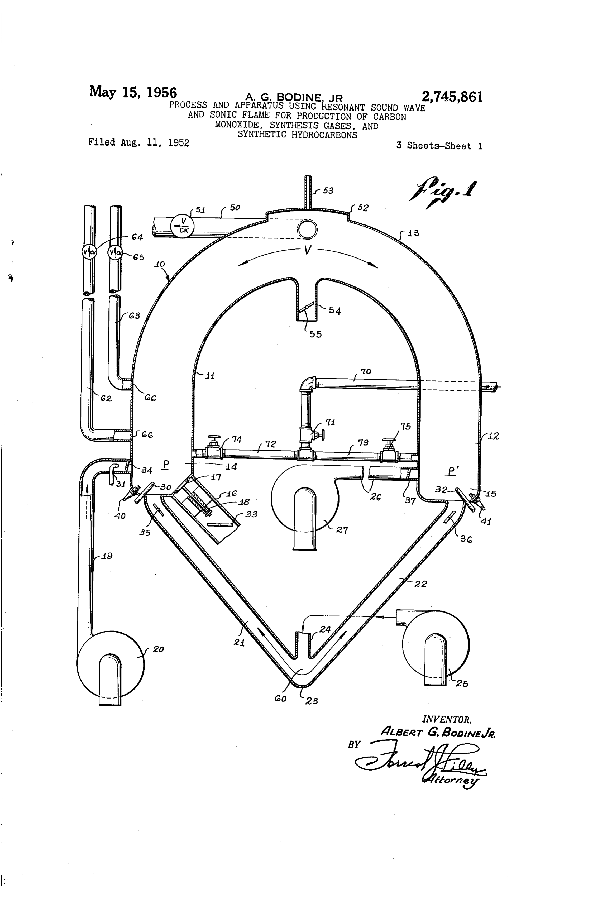
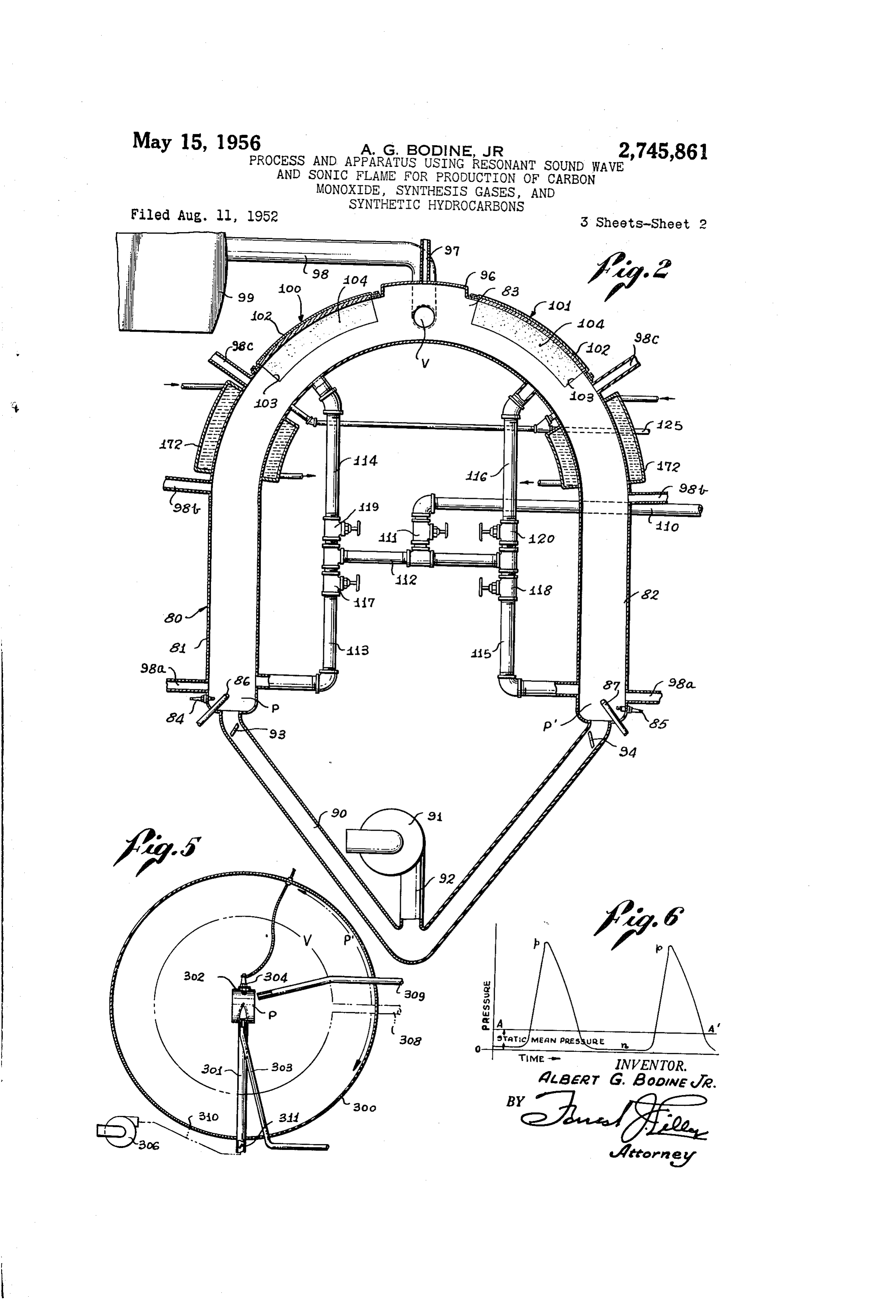
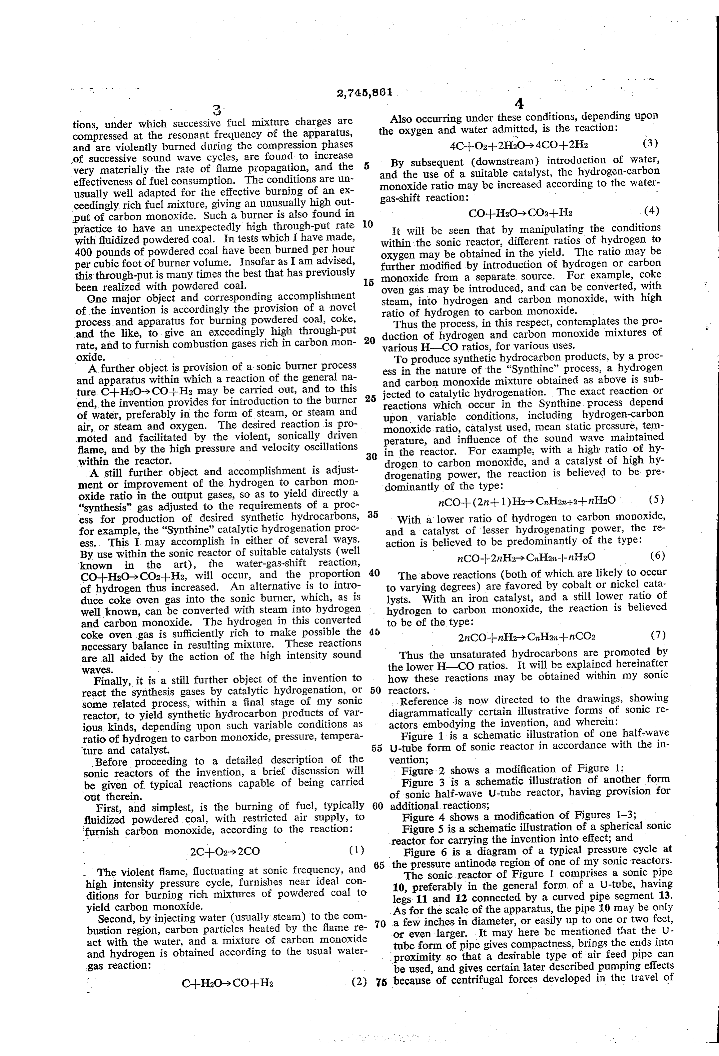
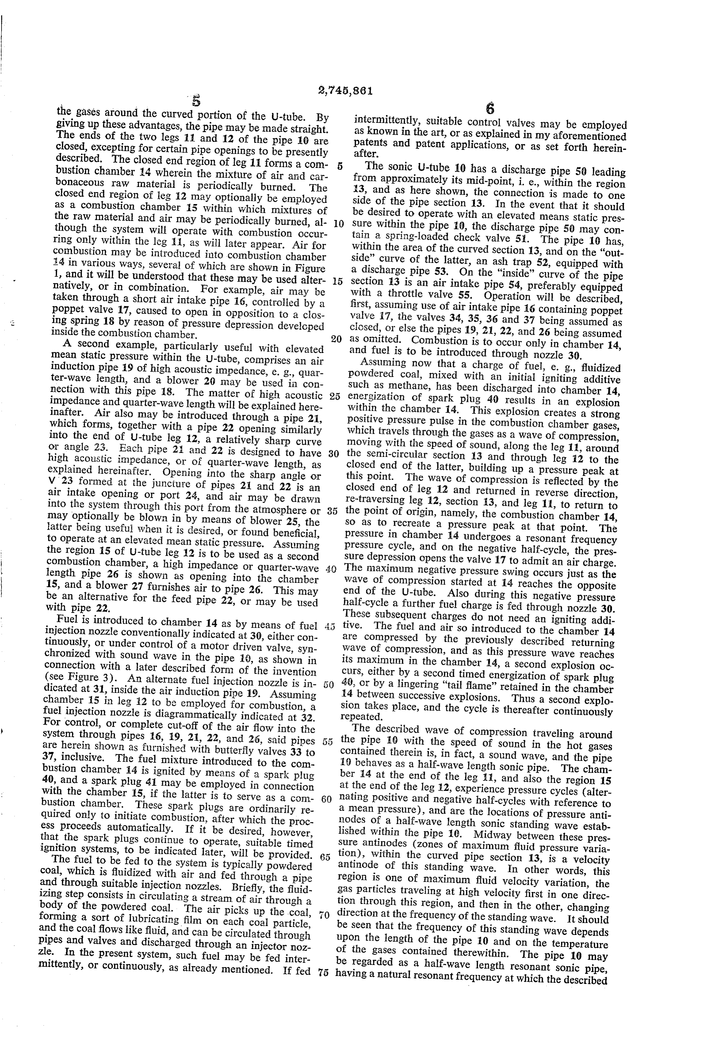
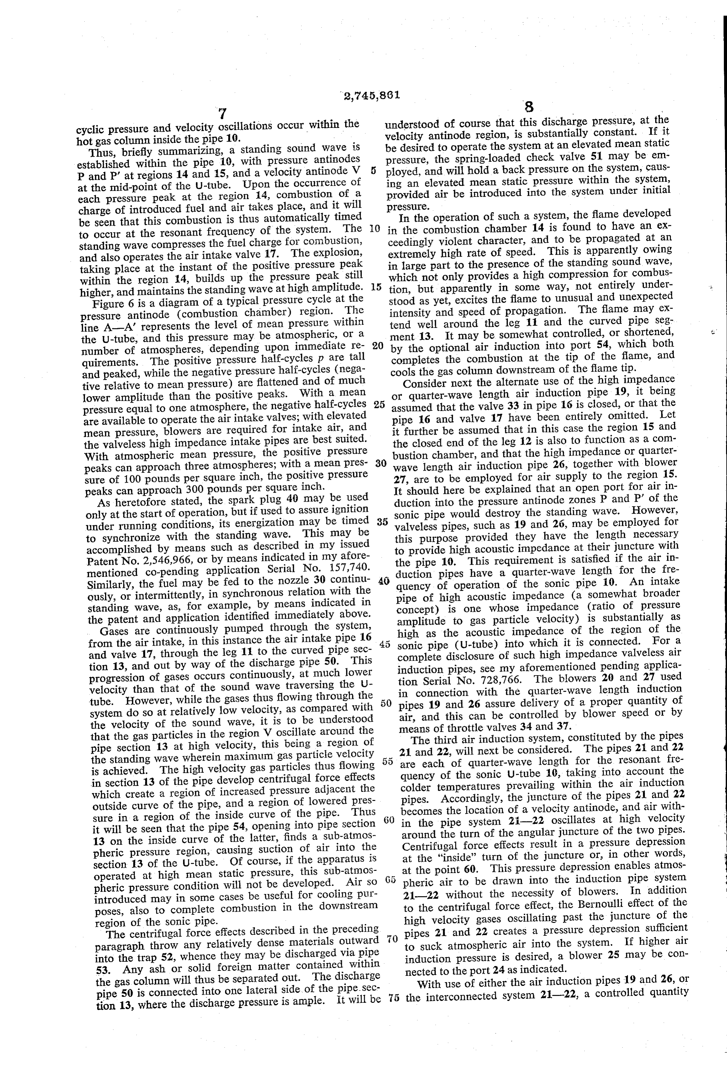
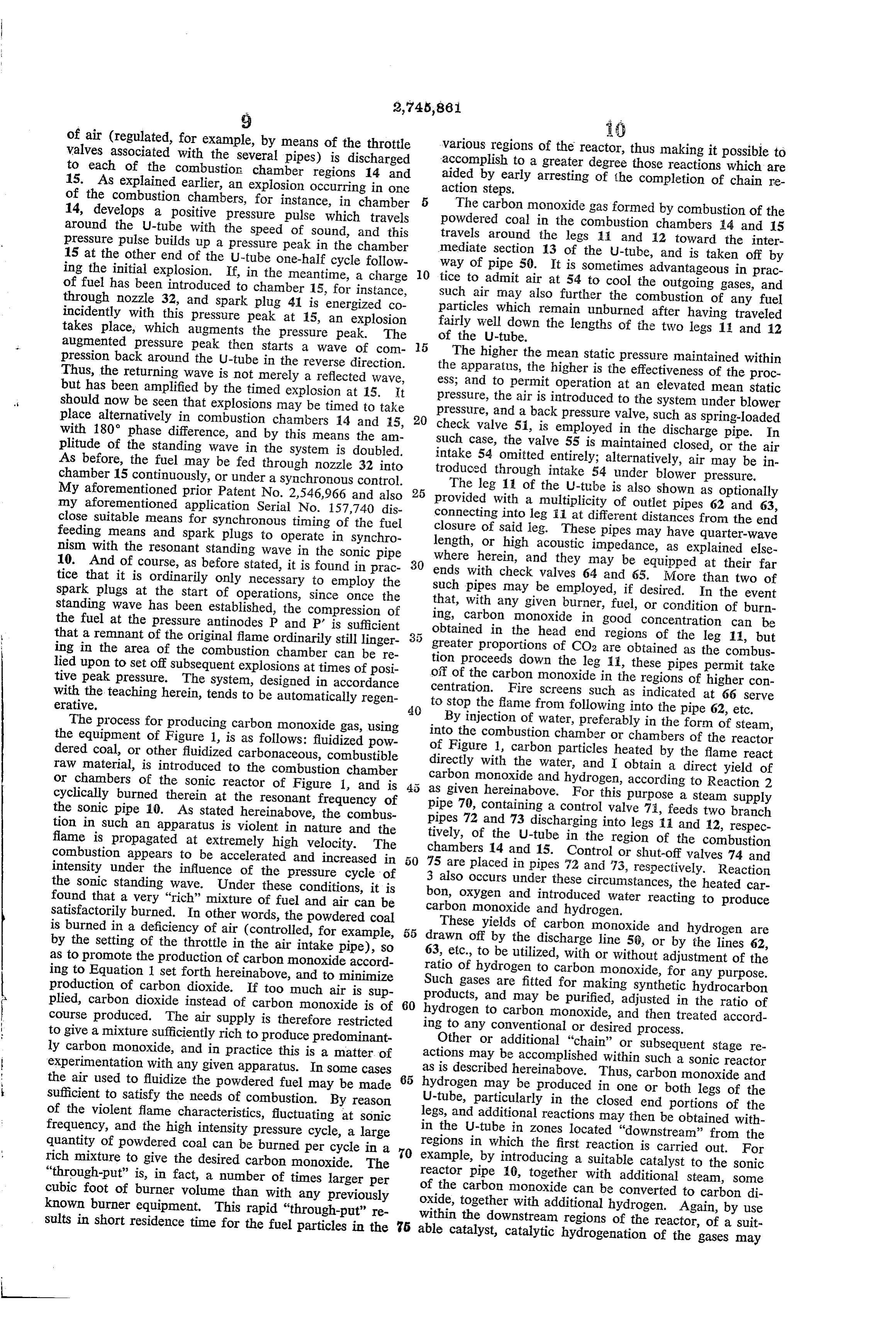
Some related process, within a final stage of my sonic Reference is now directed to the drawings, showing reactor, to yield synthetic hydrocarbon products of var diagrammatically certain illustrative forms of sonic re ious kinds, depending upon such variable conditions as actors embodying the invention, and wherein: ratio of hydrogen to carbon monoxide, pressure, tempera Figure 1 is a schematic illustration of one half-wave ture and catalyst. - 55 U-tube form of sonic reactor in accordance with the in Before proceeding to a detailed description of the vention;
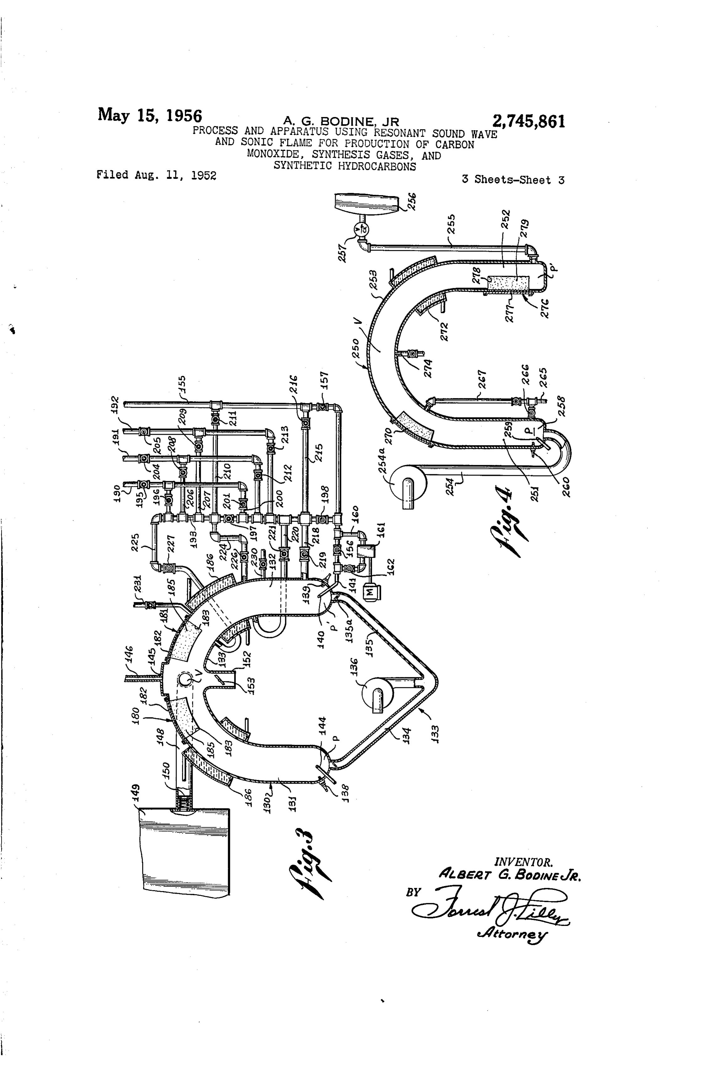
sonic reactors of the invention, a brief discussion will Figure 2 shows a modification of Figure 1; be given of typical reactions capable of being carried Figure 3 is a schematic illustration of another form out therein. of sonic half-wave U-tube reactor, having provision for First, and simplest, is the burning of fuel, typically 60 additional reactions;
fluidized powdered coal, with restricted air supply, to Figure 4 shows a modification of Figures 1-3; furnish carbon monoxide, according to the reaction: Figure 5 is a schematic illustration of a spherical sonic reactor for carrying the invention into effect; and 2C--O2)2CO (1) Figure 6 is a diagram of a typical pressure cycle at 65 the pressure antinode region of one of my sonic reactors.
- The violent flame, fluctuating at sonic frequency, and The sonic reactor of Figure 1 comprises a sonic pipe high intensity pressure cycle, furnishes near ideal con 10, preferably in the general form of a U-tube, having ditions for burning rich mixtures of powdered coal to legs 11 and 12 connected by a curved pipe segment 13. yield carbon monoxide. As for the scale of the apparatus, the pipe 10 may be only Second, by injecting water (usually steam) to the com a few inches in diameter, or easily up to one or two feet, bustion region, carbon particles heated by the flame re 70 or even larger. It may here be mentioned that the U act with the water, and a mixture of carbon monoxide tube form of pipe gives compactness, brings the ends into and hydrogen is obtained according to the usual water proximity so that a desirable type of air feed pipe can gas reaction: - be used, and gives certain later described pumping effects C--H2O-> CO--He (2) 75 because of centrifugal forces developed in the travel of
Page 6
the gases around the curved portion of the U-tube. By intermittently, suitable control 6 giving up these advantages, the pipe may be made straight. as known in the art, or as explained valves may be employed The ends of the two legs 11 and 12 of the pipe 10 are in my aforementioned closed, excepting for certain pipe openings to be presently patents after.
and patent applications, or as set forth herein described. The closed end region of leg 1 forms a com The sonic U-tube 10 has a discharge pipe 50 leading bustion channber 14 wherein the mixture of air and car bonaceous raw material is periodically burned. The from approximately its mid-point, i. e., within the region closed end region of leg 2 may optionally be employed 3, and as here shown, the connection is made to one as a combustion chamber 15 within which mixtures of side of the pipe section 13. In the event that it should the raw material and air may be periodically burned, al 10 sure be desired to operate with an elevated means static pres though the system will operate with combustion occur tain awithin the pipe 10, the discharge pipe 50 may con spring-loaded check valve 5. The pipe 10 has, ring only within the leg 1, as will later appear. Air for within the combustion may be introduced into combustion chamber side” curvearea of the curved section 13, and on the "out of the latter, an ash trap 52, equipped with 34 in various ways, several of which are shown in Figure a discharge pipe 53. On the "inside" curve of the pipe 1, and it will be understood that these may be used alter 5 section 13 is an air intake pipe 54, preferably equipped natively, or in combination. For example, air may be with a throttle valve 55. Operation will be described, taken through a short air intake pipe 16, controlled by a first, assuming use of air intake pipe 6 containing poppet poppet valve 17, caused to open in opposition to a clos valve 17, the valves 34, 35, 36 and 37 being assumed as 3. ing spring 18 by reason of pressure depression developed closed, or else the pipes 19, 21, 22, and 26 being assumed inside the combustion chamber. 20
A second example, particularly useful with elevated as omitted. Combustion is to occur only in chamber 14, and fuel is to be introduced through nozzle 30.
mean static pressure within the U-tube, comprises an air Assurning now that a charge of fuel, e. g., fluidized induction pipe 19 of high acoustic impedance, e.g., quar powdered coal, mixed with an initial igniting additive ter-wave length, and a blower 20 may be used in con such as methane, has been discharged into chamber 14, nection with this pipe 18. The matter of high acoustic 25 energization of spark plug 40 results in an explosion impedance and quarter-wave length will be explained here within the chamber 4. This explosion creates a strong inafter. Air also may be introduced through a pipe 21, positive pressure pulse in the combustion chamber gases, which forms, together with a pipe 22 opening similarly which travels through the gases as a wave of compression, into the end of U-tube leg 12, a relatively sharp curve moving with the speed of sound, along the leg 11, around or angle 23. Each pipe 2 and 22 is designed to have 30 the semi-circular section 13 and through leg 12 to the high acoustic impedance, or of quarter-wave length, as closed end of the latter, building up a pressure peak at explained hereinafter. Opening into the sharp angle or this point. The wave of compression is reflected by the V 23 formed at the juncture of pipes 2 and 22 is an closed end of leg 12 and returned in reverse direction, air intake opening or port 24, and air may be drawn re-traversing leg 12, section 3, and leg 11, to return to into the system through this port from the atmosphere or 35 the point of origin, namely, the combustion chamber 14, may optionally be blown in by means of blower 25, the so as to recreate a pressure peak at that point. The latter being useful when it is desired, or found beneficial, pressure in chamber 14 undergoes a resonant frequency to operate at an elevated mean static pressure. Assuming pressure cycle, and on the negative half-cycle, the pres the region 5 of U-tube leg 12 is to be used as a second sure depression opens the valve 17 to admit an air charge. combustion chamber, a high impedance or quarter-wave 40 The maximum negative pressure swing occurs just as the length pipe 26 is shown as opening into the chamber wave of compression started at 14 reaches the opposite 15, and a blower 27 furnishes air to pipe 26. This may end of the U-tube. Also during this negative pressure be an alternative for the feed pipe 22, or may be used half-cycle a further fuel charge is fed through nozzle 30. with pipe 22.
Fuel is introduced to chamber 14 as by means of fuel These subsequent charges do not need an igniting addi injection nozzle conventionally indicated at 30, either con tive. The fuel and air so introduced to the chamber 14 tinuously, or under control of a motor driven valve, syn are compressed by the previously described returning chronized with sound wave in the pipe 10, as shown in wave of compression, and as this pressure wave reaches connection with a later described form of the invention its maximum in the chamber 14, a second explosion oc (see Figure 3). An alternate fuel injection nozzle is in curs, either by a second timed energization of spark plug dicated at 31, inside the air induction pipe 19. Assuming 40, or by a lingering “tail flame' retained in the chamber chamber 5 in leg 2 to be employed for combustion, a sion 4 between successive explosions. Thus a second explo fuel injection nozzle is diagrammatically indicated at 32. takes place, and the cycle is thereafter continuously repeated.
For control, or complete cut-off of the air flow into the system through pipes 16, 19, 2, 22, and 25, said pipes 55 theThe described wave of compression traveling around pipe 16 with the speed of sound in the hot gases are herein shown as furnished with butterfly valves 33 to contained therein is, in fact, a sound wave, and the pipe 37, inclusive. The fuel mixture introduced to the com is behaves as a half-wave length sonic pipe. The cham bustion chamber 4 is ignited by means of a spark plug ber 4 at the end of the leg i, and also the region 15 40, and a spark plug 41 may be employed in connection at the end of the leg 12, experience pressure cycles (alter with the chamber 15, if the latter is to serve as a com 60 nating bustion chamber. These spark plugs are ordinarily re a meanpositive and negative half-cycles with reference to pressure), and are the locations of pressure anti quired only to initiate combustion, after which the proc nodes of a half-wave length sonic standing wave estab ess proceeds automatically. If it be desired, however, lished within the pipe 10. Midway between these pres that the spark plugs continue to operate, suitable timed sure antinodes (zones of maximum fluid pressure varia ignition systems, to be indicated later, will be provided. tion), within the curved pipe section 13, is a velocity The fuel to be fed to the system is typically powdered antinode of this standing wave. In other words, this coal, which is fluidized with air and fed through a pipe region is one of maximum fluid velocity variation, the and through suitable injection nozzles. Briefly, the fluid gas particles traveling at high velocity first in one direc izing step consists in circulating a stream of air through a tion through this region, and then in the other, changing body of the powdered coal. The air picks up the coal, forming a sort of lubricating film on each coal particle, direction at the frequency of the standing wave. It should and the coal flows like fluid, and can be circulated through be seen that the frequency of this standing wave depends pipes and valves and discharged through an injector noz upon the length of the pipe 0 and on the temperature zle. In the present system, such fuel may be fed inter of the gases contained therewithin. The pipe 10 may mittently, or continuously, as already mentioned. If fed 75 be regarded as a half-wave length resonant sonic pipe, having a natural resonant frequency at which the described
Page 7
cyclic pressure and velocity oscillations occur within the understood of course that this discharge pressure, at the hot gas column inside the pipe 10. velocity antinode region, is substantially constant. If it Thus, briefly summarizing, a standing sound wave is be desired to operate the system at an elevated mean static established within the pipe 10, with pressure antinodes pressure, the spring-loaded check valve 51 may be em P and P' at regions 14 and 15, and a velocity antinode V ployed, and will hold a back pressure on the system, caus at the mid-point of the U-tube. Upon the occurrence of ing an elevated mean static pressure within the system, each pressure peak at the region 14, combustion of a provided air be introduced into the system under initial charge of introduced fuel and air takes place, and it will pressure.
be seen that this combustion is thus automatically timed 0. in Inthethecombustion operation of such a system, the flame developed chamber 14 is found to have an ex to occur at the resonant frequency of the system. The standing wave compresses the fuel charge for combustion, ceedingly violent character, and to be propagated at an and also operates the air intake valve 17. The explosion, extremely high rate of speed. This is apparently owing taking place at the instant of the positive pressure peak in large part to the presence of the standing sound wave, within the region 14, builds up the pressure peak still 5 which not only provides a high compression for combus higher, and maintains the standing wave at high amplitude. tion, but apparently in some way, not entirely under Figure 6 is a diagram of a typical pressure cycle at the stood as yet, excites the flame to unusual and unexpected pressure antinode (combustion chamber) region. The intensity and speed of propagation. The flame may ex line A-A represents the level of mean pressure within tend well around the leg 11 and the curved pipe seg the U-tube, and this pressure may be atmospheric, or a 20 ment 13. It may be somewhat controlled, or shortened, number of atmospheres, depending upon immediate re by the optional air induction into port 54, which both quirements. The positive pressure half-cycles p are tall completes the combustion at the tip of the flame, and and peaked, while the negative pressure half-cycles (nega cools the gas column downstream of the flame tip. tive relative to mean pressure) are flattened and of much Consider next the alternate use of the high impedance lower amplitude than the positive peaks. With a mean 25 or quarter-wave length air induction pipe 19, it being pressure equal to one atmosphere, the negative half-cycles assumed that the valve 33 in pipe 16 is closed, or that the are available to operate the air intake valves; with elevated pipe 16 and valve 17 have been entirely omitted. Let mean pressure, blowers are required for intake air, and it further be assumed that in this case the region 15 and the valveless high impedance intake pipes are best Suited. the closed end of the leg 12 is also to function as a com With atmospheric mean pressure, the positive pressure bustion chamber, and that the high impedance or quarter peaks can approach three atmospheres; with a mean pres 30 wave length air induction pipe 26, together with blower sure of 100 pounds per square inch, the positive pressure 27, are to be employed for air supply to the region 15. peaks can approach 300 pounds per square inch. It should here be explained that an open port for air in As heretofore stated, the spark plug 40 may be used duction into the pressure antinode zones P and P' of the only at the start of operation, but if used to assure ignition Sonic pipe would destroy the standing wave. However, under running conditions, its energization may be timed 35 valveless pipes, such as 19 and 26, may be employed for to synchronize with the standing wave. This may be this purpose provided they have the length necessary accomplished by means such as described in my issued to provide high acoustic impedance at their juncture with Patent No. 2,546,966, or by means indicated in my afore the pipe 10. This requirement is satisfied if the air in mentioned co-pending application Serial No. 157,740. duction pipes have a quarter-wave length for the fre Similarly, the fuel may be fed to the nozzle 30 continu 40 quency of operation of the sonic pipe 10. An intake ously, or intermittently, in synchronous relation with the pipe of high acoustic impedance (a somewhat broader standing wave, as, for example, by means indicated in concept) is one whose impedance (ratio of pressure the patent and application identified immediately above. amplitude to gas particle velocity) is substantially as Gases are continuously pumped through the System, high as the acoustic impedance of the region of the from the air intake, in this instance the air intake pipe 16 sonic pipe (U-tube) into which it is connected. For a and valve 17, through the leg 11 to the curved pipe Sec complete disclosure of such high impedance valveless air tion 13, and out by way of the discharge pipe 50. This progression of gases occurs continuously, at much lower tion Serialpipes, induction see my aforementioned pending applica
velocity than that of the sound wave traversing the U tube. However, while the gases thus flowing through the 50 in connection with the quarter-wave length induction pipes 19 and 26 assure delivery of a proper quantity of system do so at relatively low velocity, as compared with air, and this can be controlled by blower speed or by the velocity of the sound wave, it is to be understood means of throttle valves 34 and 37. that the gas particles in the region V oscillate around the The third air induction system, constituted by the pipes pipe section 13 at high velocity, this being a region of the standing wave wherein maximum gas particle velocity 21 are and 22, will next be considered. The pipes 21 and 22 each of quarter-wave length for the resonant fre is achieved. The high velocity gas particles thus flowing quency of the sonic U-tube 10, taking into account the in section 13 of the pipe develop centrifugal force effects colder temperatures prevailing within the air induction which create a region of increased pressure adjacent the pipes. Accordingly, the juncture of the pipes 21 and 22 outside curve of the pipe, and a region of lowered pres becomes the location of a velocity antinode, and air with sure in a region of the inside curve of the pipe. Thus it will be seen that the pipe 54, opening into pipe section 60 in the pipe system 21-22 oscillates at high velocity around the turn of the angular juncture of the two pipes.
13 on the inside curve of the latter, finds a Sub-atmos Centrifugal force effects result in a pressure depression pheric pressure region, causing suction of air into the at the "inside' turn of the juncture or, in other words, section 13 of the U-tube. Of course, if the apparatus is at the point 60. This pressure depression enables atmos operated at high mean static pressure, this sub-atmos pheric pheric pressure condition will not be developed. Air So 21-22airwithout to be drawn into the induction pipe system the necessity of blowers. In addition introduced may in some cases be useful for cooling pur poses, also to complete combustion in the downstream to the centrifugal force effect, the Bernoulli effect of the region of the Sonic pipe. high velocity gases oscillating past the juncture of the The centrifugal force effects described in the preceding pipes 21 and 22 creates a pressure depression Sufficient paragraph throw any relatively dense materials outward to suck atmospheric air into the system. If higher air into the trap 52, whence they may be discharged via pipe induction pressure is desired, a blower 25 may be con 53. Any ash or solid foreign matter contained within the gas column will thus be separated out. The discharge nected to the port 24 as indicated. With use of either the air induction pipes 19 and 26, or pipe 50 is connected into one lateral side of the pipe sec tion 13, where the discharge pressure is ample. It will be 5 the interconnected system 21-22, a controlled quantity
Page 8
of air (regulated, for example, by means of the throttle various regions of the reactor, thus making it possible to valves associated with the several pipes) is discharged accomplish to a greater degree those reactions which are to each of the combustion chamber regions 14 and aided by early arresting of the completion of chain re 15. As explained earlier, an explosion occurring in one action steps.
of the combustion chambers, for instance, in chamber The carbon monoxide gas formed by combustion of the 14, develops a positive pressure pulse which travels powdered coal in the combustion chambers 4 and 15 around the U-tube with the speed of sound, and this travels around the legs 4 and 12 toward the inter pressure pulse builds up a pressure peak in the chamber mediate section 13 of the U-tube, and is taken off by 15 at the other end of the U-tube one-half cycle follow way of pipe 50. It is sometimes advantageous in prac ing the initial explosion. If, in the meantime, a charge O tice to admit air at 54 to cool the outgoing gases, and of fuel has been introduced to chamber 15, for instance, such air may also further the combustion of any fuel through nozzle 32, and spark plug 41 is energized co incidently with this pressure peak at 15, an explosion particles which remain unburned after having traveled takes place, which augments the pressure peak. The fairly well down the lengths of the two legs 1 and 12 of the U-tube.
augmented pressure peak then starts a wave of com pression back around the U-tube in the reverse direction. The higher the mean static pressure maintained within Thus, the returning wave is not merely a reflected wave, the apparatus, the higher is the effectiveness of the proc but has been amplified by the timed explosion at 15. It ess; and to permit operation at an elevated mean static should now be seen that explosions may be timed to take pressure, the air is introduced to the system under blower place alternatively in combustion chambers 14 and 5, 20 pressure, and a back pressure valve, such as spring-loaded check valve 51, is employed in the discharge pipe. In with 180° phase difference, and by this means the am plitude of the standing wave in the system is doubled. such case, the valve 55 is maintained closed, or the air As before, the fuel may be fed through nozzle 32 into intake 54 omitted entirely; alternatively, air may be in chamber 15 continuously, or under a synchronous control. troduced through intake 54 under blower pressure. My aforementioned prior Patent No. 2,546,966 and also 25 provided The leg 1 of the U-tube is also shown as optionally my aforementioned application Serial No. 157,740 dis connectingwith a multiplicity of outlet pipes 62 and 63, into leg ii at different distances from the end close suitable means for synchronous timing of the fuel closure of said leg. These pipes may have quarter-wave feeding means and spark plugs to operate in synchro nism with the resonant standing wave in the sonic pipe length, or high acoustic impedance, as explained else 10. And of course, as before stated, it is found in prac 30 endswhere herein, and they may be equipped at their far tice that it is ordinarily only necessary to employ the with check valves 64 and 65. More than two of such spark plugs at the start of operations, since once the that, with any pipes may be employed, if desired. In the event standing wave has been established, the compression of given burner, fuel, or condition of burn the fuel at the pressure antinodes P and P' is sufficient ing, carbon monoxide in good concentration can be that a remnant of the original flame ordinarily still linger obtained in the head end regions of the leg 11, but ing in the area of the combustion chamber can be re greater proportions of CO2 are obtained as the combus lied upon to set off subsequent explosions at times of posi tion proceeds down the leg 11, these pipes permit take off of the carbon monoxide in the regions of higher con tive peak pressure. The system, designed in accordance centration.
with the teaching herein, tends to be automatically regen Fire screens such as indicated at 66 serve erative. 40 to stop the fame from following into the pipe 62, etc. The process for producing carbon monoxide gas, using By injection of water, preferably in the form of steam, the equipment of Figure 1, is as follows: fluidized pow into the combustion chamber or chambers of the reactor of Figure 1, carbon particles heated by the flame react dered coal, or other fluidized carbonaceous, combustible directly raw material, is introduced to the combustion chamber carbon with the water, and I obtain a direct yield of or chambers of the sonic reactor of Figure 1, and is monoxide and hydrogen, according to Reaction 2 cyclically burned therein at the resonant frequency of as given hereinabove. For this purpose a steam supply the sonic pipe 10. As stated hereinabove, the combus pipes pipe 70, containing a control valve 73, feeds two branch tion in such an apparatus is violent in nature and the 72 and 73 discharging into legs i and 12, respec flame is propagated at extremely high velocity. The tively, of the U-tube in the region of the combustion combustion appears to be accelerated and increased in chambers 14 and 15. Control or shut-off valves 74 and intensity under the influence of the pressure cycle of 50 75 are placed in pipes 72 and 73, respectively. Reaction the sonic standing wave. Under these conditions, it is bon, 3 also occurs under these circumstances, the heated car found that a very "rich' mixture of fuel and air can be carbon oxygen and introduced water reacting to produce satisfactorily burned. In other words, the powdered coal monoxide and hydrogen. is burned in a deficiency of air (controlled, for example, 55 These yields of carbon monoxide and hydrogen are by the setting of the throttle in the air intake pipe), so drawn off by the discharge line 56, or by the lines 62, as to promote the production of carbon monoxide accord ratio 63, etc., to be utilized, with or without adjustment of the ing to Equation 1 set forth hereinabove, and to minimize Such of hydrogen to carbon monoxide, for any purpose. gases are fitted for making synthetic hydrocarbon production of carbon dioxide. If too much air is Sup products, and may be purified, adjusted in the ratio of plied, carbon dioxide instead of carbon monoxide is of 60 hydrogen to carbon monoxide, and then treated accord course produced. The air supply is therefore restricted to give a mixture sufficiently rich to produce predominant ingOther to any conventional or desired process. or additional "chain' or subsequent stage re ly carbon monoxide, and in practice this is a matter of actions may experimentation with any given apparatus. In some cases as is describedbehereinabove.
accomplished within such a sonic reactor the air used to fluidize the powdered fuel may be made 65 hydrogen may be produced Thus, carbon monoxide and in one or both legs of the sufficient to satisfy the needs of combustion. By reason U-tube, particularly in the closed end portions of the of the violent flame characteristics, fluctuating at Sonic legs, and additional reactions may then be obtained with frequency, and the high intensity pressure cycle, a large in the U-tube in zones located "downstream” from the quantity of powdered coal can be burned per cycle in a 70 regions in which the first reaction is carried out. For rich mixture to give the desired carbon monoxide. The example, by introducing a suitable catalyst to the sonic “through-put' is, in fact, a number of times larger per reactor pipe 10, together with additional steam, some cubic foot of burner volume than with any previously of the carbon monoxide can be converted to carbon di known burner equipment. This rapid "through-put' re oxide, together with additional hydrogen. Again, by use withincatalyst, sults in short residence time for the fuel particles in the 5 able the downstream regions of the of catalytic hydrogenation reactor, of a may the gases suit
Page 9
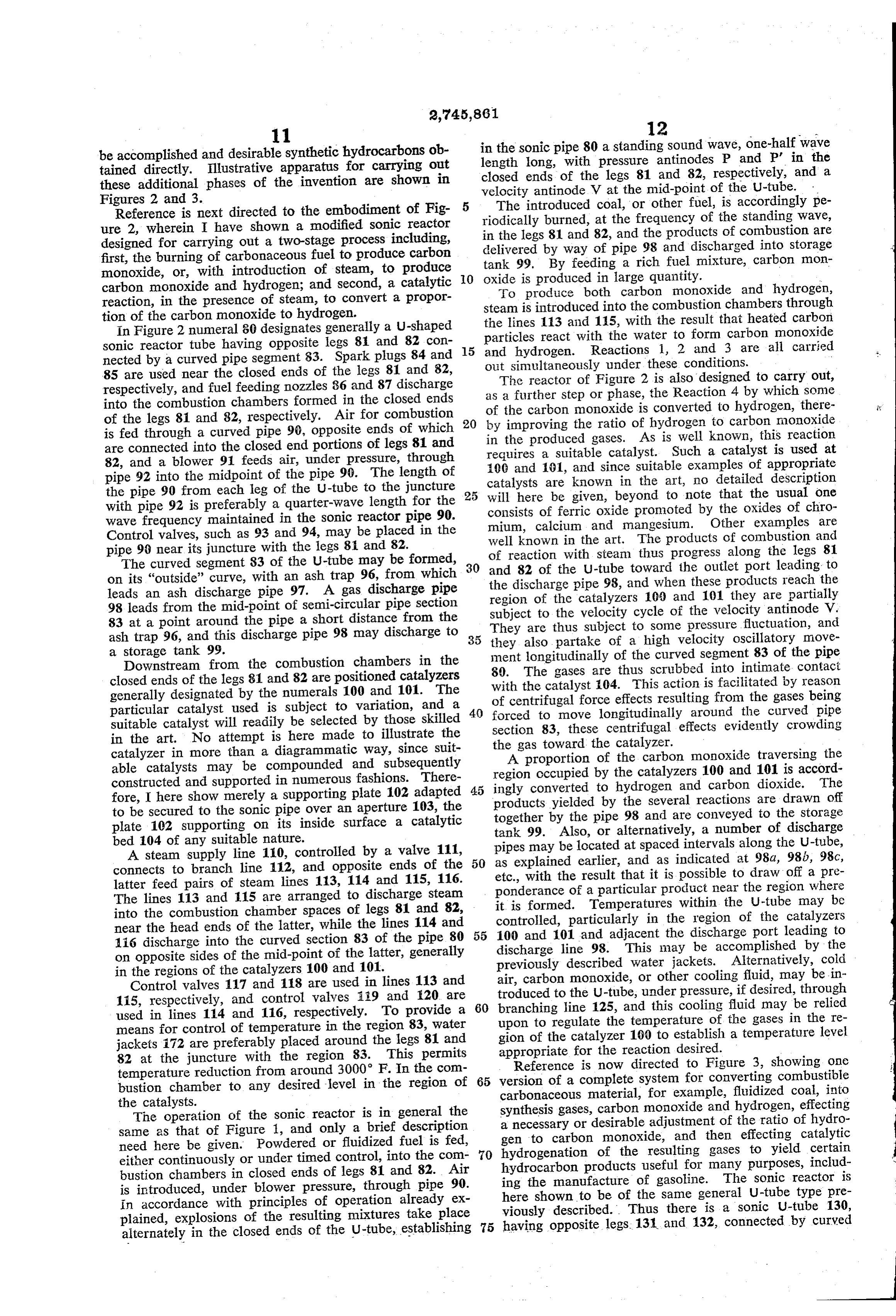
be accomplished and desirable synthetic hydrocarbons ob in the sonic pipe 80 a standing sound wave, one-half wave tained directly. Illustrative apparatus for carrying out length long, with pressure antinodes P and P' in the these additional phases of the invention are shown in closed ends of the legs 81 and 82, respectively, and a Figures 2 and 3. velocity antinode V at the mid-point of the U-tube. . Reference is next directed to the embodiment of Fig The introduced coal, or other fuel, is accordingly pe ure 2, wherein. I have shown a modified sonic reactor riodically burned, at the frequency of the standing wave, designed for carrying out a two-stage process including, in the legs 81 and 82, and the products of combustion are first, the burning of carbonaceous fuel to produce carbon delivered by way of pipe 98 and discharged into storage monoxide, or, with introduction of steam, to produce tank 99. By feeding a rich fuel mixture, carbon mon 0 oxide is produced in large quantity. - carbon monoxide and hydrogen; and second, a catalytic To produce both carbon monoxide and hydrogen, reaction, in the presence of steam, to convert a propor steam is introduced into the combustion chambers through tion of the carbon monoxide to hydrogen. the lines 113 and 115, with the result that heated carbon In Figure 2 numeral 80 designates generally a U-shaped
Sonic reactor tube having opposite legs 8 and 82 con 5 particles react with the water to form carbon monoxide and hydrogen. Reactions 1, 2 and 3 are all carried nected by a curved pipe segment 83. Spark plugs 84 and out simultaneously under these conditions. 85 are used near the closed ends of the legs 81 and 82, The reactor of Figure 2 is also designed to carry out, respectively, and fuel feeding nozzles 86 and 87 discharge as a further Step or phase, the Reaction 4 by which some into the combustion chambers formed in the closed ends of the legs 81 and 82, respectively. Air for combustion 20 of the carbon monoxide is converted to hydrogen, there by improving the ratio of hydrogen to carbon monoxide is fed through a curved pipe 90, opposite ends of which in the produced gases. As is well known, this reaction are connected into the closed end portions of legs 81 and requires a suitable catalyst. Such a catalyst is used at 82, and a blower 91 feeds air, under pressure, through 100 and 61, and since suitable examples of appropriate pipe 92 into the midpoint of the pipe 90. The length of the pipe 90 from each leg of the U-tube to the juncture 25 catalysts will here are known in the art, no detailed description be given, beyond to note that the usual one with pipe 92 is preferably a quarter-wave length for the consists of ferric oxide promoted by the oxides of chro wave frequency maintained in the sonic reactor pipe 90. mium, calcium and mangesium. Other examples are Control valves, such as 93 and 94, may be placed in the well known in the art. The products of combustion and pipe 96 near its juncture with the legs 8 and 82.
The curved segment 83 of the U-tube may be formed, 30 of and reaction with steam thus progress along the legs 81 82 of the U-tube toward the outlet port leading to on its "outside' curve, with an ash trap 96, from which leads an ash discharge pipe 97. A gas discharge pipe the discharge pipe 98, and when these products reach the region of the catalyzers 100 and 101 they are partially 98 leads from the mid-point of semi-circular pipe section subject to the velocity cycle of the velocity antinode V. 83 at a point around the pipe a short distance from the ash trap 96, and this discharge pipe 98 may discharge to 35 they also thus
They are subject to some pressure fluctuation, and partake of a high velocity oscillatory move a storage tank 99. ment longitudinally of the curved segment 83 of the pipe Downstream from the combustion chambers in the 80. The gases are thus scrubbed into intimate contact closed ends of the legs 81 and 82 are positioned catalyzers generally designated by the numerals 100 and 101. The with the catalyst 04. This action is facilitated by reason particular catalyst used is subject to variation, and a 40 of centrifugal force effects resulting from the gases being forced to move longitudinally around the curved pipe suitable catalyst will readily be selected by those skilled section 83, these centrifugal effects evidently crowding in the art. No attempt is here made to illustrate the the gas toward the catalyzer.
catalyzer in more than a diagrammatic way, since suit A proportion of the carbon monoxide traversing the able catalysts may be compounded and subsequently region occupied by the catalyzers 100 and 101 is accord constructed and supported in numerous fashions. There 45 ingly converted to hydrogen and carbon dioxide. The fore, I here show merely a supporting plate 102 adapted products yielded by the several reactions are drawn off to be secured to the sonic pipe over an aperture 103, the together by the pipe 98 and are conveyed to the storage plate 102 supporting on its inside surface a catalytic tank 99. Also, or alternatively, a number of discharge bed 104 of any suitable nature. pipes may be located at spaced intervals along the U-tube, A steam supply line 10, controlled by a valve 111, connects to branch line 112, and opposite ends of the 50 as etc., explained earlier, and as indicated at 98a, 98b, 98c, with the result that it is possible to draw off a pre latter feed pairs of steam lines 113, 114 and 115, 116. ponderance of a particular product near the region where The lines 113 and 15 are arranged to discharge steam it is formed. Temperatures within the U-tube may be into the combustion chamber spaces of legs 81 and 82, near the head ends of the latter, while the lines 114 and 55 controlled, particularly in the region of the catalyzers 100 and 101 and adjacent the discharge port leading to i6 discharge into the curved section 83 of the pipe 80 discharge line 98. This may be accomplished by the on opposite sides of the mid-point of the latter, generally previously described water jackets. Alternatively, cold in the regions of the catalyzers 100 and 101. air, carbon monoxide, or other cooling fluid, may be in Control valves 117 and 118 are used in lines. 113 and 115, respectively, and control valves 19 and 20 are troduced to the U-tube, under pressure, if desired, through used in lines 114 and 116, respectively. To provide a 60 branching line 125, and this cooling fluid may be relied upon to regulate the temperature of the gases in the re means for control of temperature in the region 83, water gion of the catalyzer 100 to establish a temperature level jackets 172 are preferably placed around the legs 81 and appropriate for the reaction desired. 82 at the juncture with the region 83. This permits Reference is now directed to Figure 3, showing one temperature reduction from around 3000 F. In the com bustion chamber to any desired level in the region of 65 version of a complete system for converting combustible carbonaceous material, for example, fluidized coal, into the catalysts. synthesis gases, carbon monoxide and hydrogen, effecting The operation of the sonic reactor is in general the a necessary or desirable adjustment of the ratio of hydro same as that of Figure 1, and only a brief description gen to carbon monoxide, and then effecting catalytic need here be given. Powdered or fluidized fuel is fed, hydrogenation of the resulting gases to yield certain either continuously or under timed control, into the com 70 hydrocarbon products useful for many purposes, includ bustion chambers in closed ends of legs 81 and 82. Air ing the manufacture of gasoline. The sonic reactor is is introduced, under blower pressure, through pipe 90. here shown to be of the same general U-tube type pre in accordance with principles of operation already ex viously described. Thus there is a sonic U-tube 130, plained, explosions of the resulting mixtures take place having opposite legs. 131 and 132, connected by curved alternately in the closed ends of the U-tube, establishing 75
Page 10
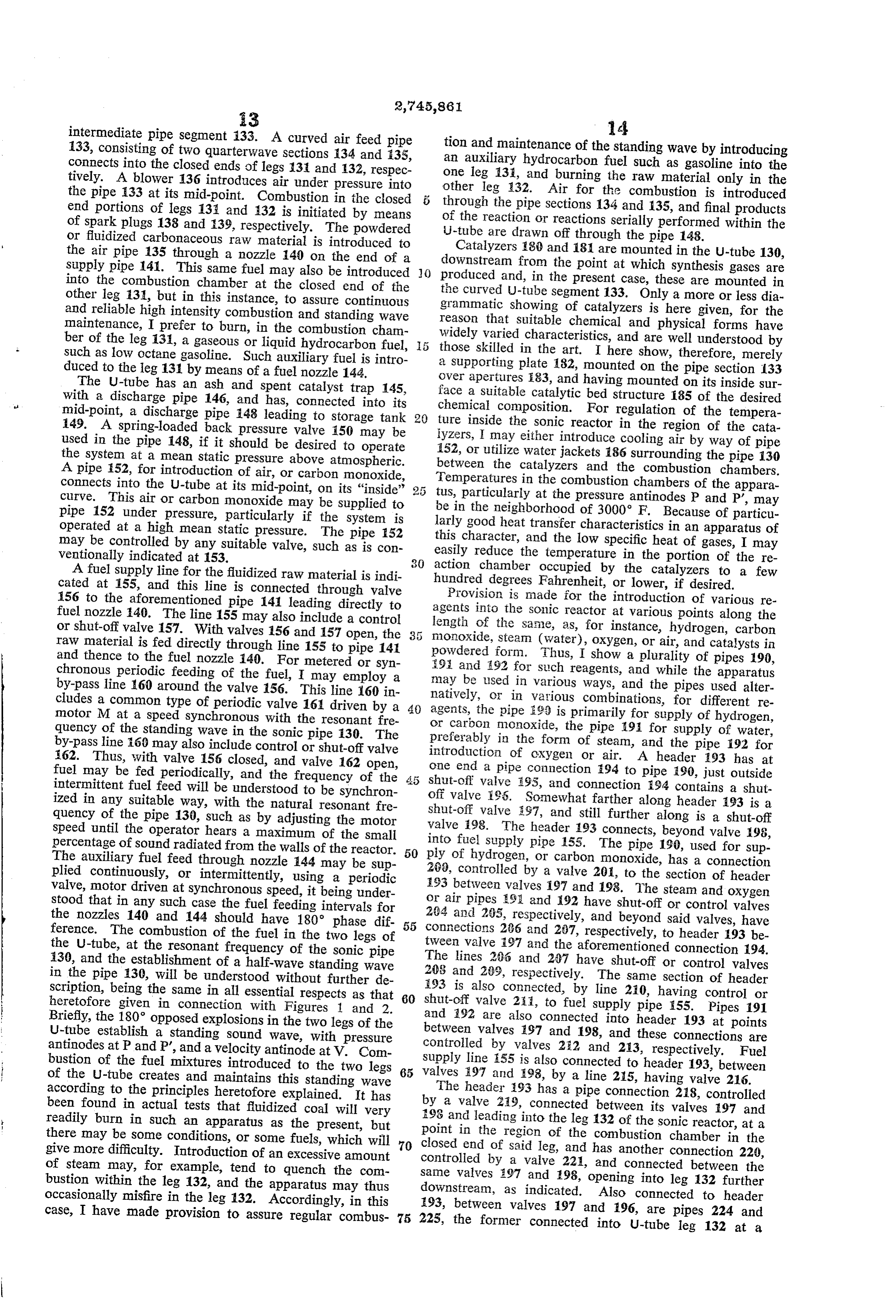
intermediate pipe segment 133. A curved air feed pipe tion and maintenance of the standing wave by introducing 133, consisting of two quarterwave sections 34 and 35, an auxiliary hydrocarbon fuel such as gasoline into the connects into the closed ends of legs 3 and 132, respec one leg 131, and burning the raw material only in the tively. A blower 136 introduces air under pressure into other leg 32. Air for the combustion is introduced the pipe 133 at its mid-point. Combustion in the closed through the pipe sections 134 and 135, and final products end portions of legs 131 and 132 is initiated by means of the reaction or reactions serially performed within the of spark plugs 138 and 39, respectively. The powdered J-tube are drawn off through the pipe 148. or fluidized carbonaceous raw material is introduced to the air pipe 135 through a nozzle 140 on the end of a Catalyzers 180 and 18 are mounted in the U-tube 130, downstream from the point at which synthesis gases are supply pipe 141. This same fuel may also be introduced () produced into the combustion chamber at the closed end of the and, in the present case, these are mounted in other leg 31, but in this instance, to assure continuous the curved U-tube segment 133. Only a more or less dia and reliable high intensity combustion and standing wave grammatic showing of catalyzers is here given, for the reason that suitable chemical and physical forms have maintenance, I prefer to burn, in the combustion cham widely varied characteristics, and are well understood by ber of the leg 131, a gaseous or liquid hydrocarbon fuel, such as low octane gasoline. Such auxiliary fuel is intro athose skilled in the art. I here show, therefore, merely supporting plate 182, mounted on the pipe section 33 duced to the leg 131 by means of a fuel nozzle 144. over apertures i83, and having mounted on its inside sur The U-tube has an ash and spent catalyst trap 145, face a suitable catalytic bed structure i85 of the desired with a discharge pipe 146, and has, connected into its mid-point, a discharge pipe 148 leading to storage tank 20 chemical composition. For regulation of the tempera 149. A spring-loaded back pressure valve 150 may be ture inside the sonic reactor in the region of the cata used in the pipe 148, if it should be desired to operate 152,yzers, I may either introduce cooling air by way of pipe the system at a mean static pressure above atmospheric. or utilize water jackets 86 surrounding the pipe 130 between the catalyzers and the combustion chambers.
A pipe 52, for introduction of air, or carbon monoxide, Temperatures connects into the U-tube at its mid-point, on its “inside' tus, particularlyin atthethecombustion chambers of the appara pressure antinodes P and P', may curve. This air or carbon monoxide may be supplied to be in the neighborhood of 3000 F. Because of particu pipe 152 under pressure, particularly if the system is operated at a high mean static pressure. The pipe 52 larly good heat transfer characteristics in an apparatus of may be controlled by any suitable valve, such as is con this character, and the low specific heat of gases, I may ventionally indicated at 153. easily reduce the temperature in the portion of the re A fuel supply line for the fluidized raw material is indi action chamber occupied by the catalyzers to a few cated at 55, and this line is connected through valve hundred degrees Fahrenheit, or lower, if desired. 156 to the aforementioned pipe 141 leading directly to agents Provision is made for the introduction of various re fuel nozzle 40. The line 155 may also include a control into the Sonic reactor at various points along the or shut-off valve 157. With valves 156 and 157 open, the length of the same, as, for instance, hydrogen, carbon raw material is fed directly through line 155 to pipe 14 monoxide, steam (water), oxygen, or air, and catalysts in and thence to the fuel nozzle 140. For metered or syn powdered form. Thus, I show a plurality of pipes 190, 593 and 92 for such reagents, and while the apparatus chronous periodic feeding of the fuel, I may employ a by-pass line 60 around the valve 156. This line 160 in may be used in various ways, and the pipes used alter natively, or in various combinations, for different re cludes a common type of periodic valve 161 driven by a 40 agents, motor M at a speed synchronous with the resonant fre the pipe 93 is primarily for supply of hydrogen, quency of the standing wave in the sonic pipe 30. The or carbon monoxide, the pipe 9 for supply of water, preferably in the form of steam, and the pipe 192 for by-pass line 60 may also include control or shut-off valve introduction 62. Thus, with valve 56 closed, and valve 162 open, of oxygen or air. A header 193 has at fuel may be fed periodically, and the frequency of the 4.5 one end a pipe connection 194 to pipe 90, just outside intermittent fuel feed will be understood to be synchron shut-off valve 95, and connection 94 contains a shut ized in any suitable way, with the natural resonant fre off valve 95. Somewhat farther along header 193 is a quency of the pipe 130, such as by adjusting the motor shut-off valve 97, and still further along is a shut-off speed until the operator hears a maximum of the small valve 98. The header 193 connects, beyond valve 198, percentage of sound radiated from the walls of the reactor. into fuel supply pipe 155. The pipe 190, used for sup The auxiliary fuel feed through nozzle 44 may be sup 50 ply of hydrogen, or carbon monoxide, has a connection plied continuously, or intermittently, using a periodic 290, controlled by a valve 20, to the section of header valve, motor driven at synchronous speed, it being under 193 between valves 197 and 198. The steam and oxygen stood that in any such case the fuel feeding intervals for or air pipes 98 and 92 have shut-off or control valves the nozzles 140 and 144 should have 180° phase dif 294 and 285, respectively, and beyond said valves, have ference. The combustion of the fuel in the two legs of 55 connections 286 and 287, respectively, to header 193 be the U-tube, at the resonant frequency of the sonic pipe tween valve 197 and the aforementioned connection 94. 130, and the establishment of a half-wave standing wave The lines 266 and 287 have shut-off or control valves in the pipe 130, will be understood without further de 203 and 299, respectively. The same section of header scription, being the same in all essential respects as that 93 is also connected, by line 210, having control or heretofore given in connection with Figures 1 and 2. 60 shut-off valve 2 ill, to fuel supply pipe 55. Pipes 191 Briefly, the 180' opposed explosions in the two legs of the and 92 are also connected into header 193 at points U-tube establish a standing sound wave, with pressure between valves 497 and 198, and these connections are antinodes at P and P', and a velocity antinode at V. Com controlled by valves 252 and 213, respectively. Fuel bustion of the fuel mixtures introduced to the two legs 65 Supply line i55 is also connected to header 193, between of the U-tube creates and maintains this standing wave valves i97 and 98, by a line 25, having valve 216. according to the principles heretofore explained. It has The header 193 has a pipe connection 218, controlled been found in actual tests that fluidized coal will very by a valve 259, connected between its valves 197 and readily burn in such an apparatus as the present, but 198 and leading into the leg 132 of the sonic reactor, at a there may be some conditions, or some fuels, which will 70 point in the region of the combustion chamber in the closed end of said leg, and has another connection 220, give more difficulty. Introduction of an excessive amount controlled of steam may, for example, tend to quench the com by a valve 22, and connected between the bustion within the leg 32, and the apparatus may thus same valves 197 and 98, opening into leg 132 further occasionally misfire in the leg 132. Accordingly, in this downstream, as indicated. Also connected to header case, I have made provision to assure regular combus 75 225, 93, between valves 197 and 196, are pipes 224 and the former connected into U-tube leg 132 at a
Page 11
steam is introduced in the general region to which th
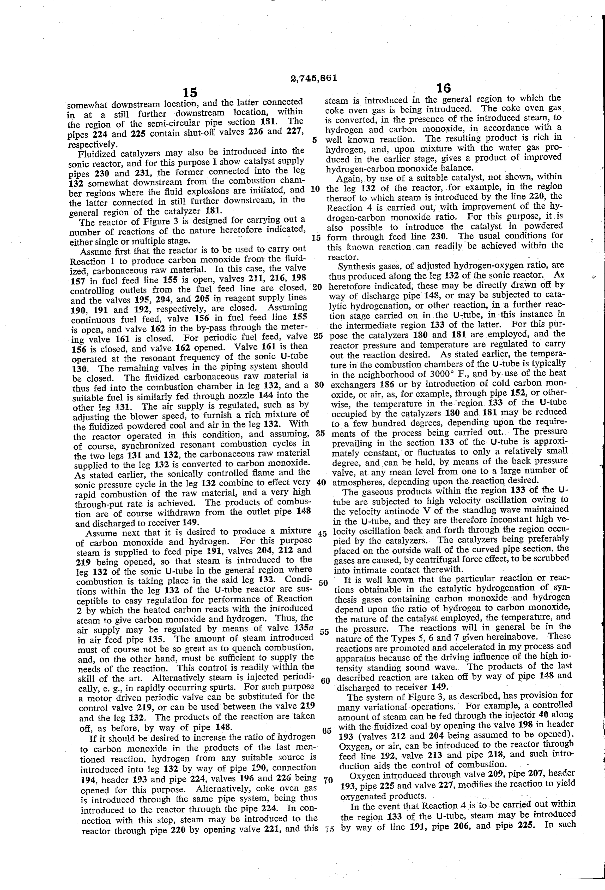
somewhat downstream location, and the latter connected coke oven gas is being introduced. The coke oven gas in at a still further downstream location, within is converted, in the presence of the introduced steam, to the region of the semi-circular pipe section 131. The hydrogen and carbon monoxide, in accordance with a pipes 224 and 225 contain shut-off valves 226 and 227, well known reaction. The resulting product is rich in respectively. hydrogen, and, upon mixture with the water gas pro Fluidized catalyzers may also be introduced into the duced in the earlier stage, gives a product of improved sonic reactor, and for this purpose I show catalyst supply pipes 230 and 231, the former connected into the leg hydrogen-carbon monoxide balance. Again, by use of a suitable catalyst, not shown, within 132 somewhat downstream from the combustion cham ber regions where the fluid explosions are initiated, and 10 the leg 132 of the reactor, for example, in the region thereof to which steam is introduced by the line 220, the the latter connected in still further downstream, in the Reaction 4 is carried out, with improvement of the hy general region of the catalyzer 181. drogen-carbon monoxide ratio. For this purpose, it is The reactor of Figure 3 is designed for carrying out a also number of reactions of the nature heretofore indicated, 5 form possible to introduce the catalyst in powdered through feed line 230. The usual conditions for either single or multiple stage. ---
Assume first that the reactor is to be used to carry out this known reaction can readily be achieved within the Reaction 1 to produce carbon monoxide from the fluid reactor. - - Synthesis gases, of adjusted hydrogen-oxygen ratio, are ized, carbonaceous raw material. In this case, the valve thus produced along the leg 132 of the sonic reactor. As c 157 in fuel feed line 155 is open, valves 211, 216, 198 heretofore indicated, these may be directly drawn off by controlling outlets from the fuel feed line are closed, 20 way of discharge pipe 148, or may be subjected to cata and the valves 195, 294, and 205 in reagent supply lines lytic hydrogenation, or other reaction, in a further reac 190, 191 and 192, respectively, are closed. Assuming continuous fuel feed, valve 156 in fuel feed line 155 tion stage carried on in the U-tube, in this instance in is open, and valve 162 in the by-pass through the meter 25 the intermediate region 133 of the latter. For this pur ing valve 161 is closed. For periodic fuel feed, valve pose the catalyzers 180 and 181 are employed, and the 156 is closed, and valve 162 opened. Valve 61 is then reactor pressure and temperature are regulated to carry operated at the resonant frequency of the sonic U-tube out the reaction desired. As stated earlier, the tempera 130. The remaining valves in the piping system should ture in the combustion chambers of the U-tube is typically be closed. The fluidized carbonaceous raw material is in the neighborhood of 3000 F., and by use of the heat thus fed into the combustion chamber in leg 132, and a 30 eXchangers 186 or by introduction of cold carbon mon oxide, or air, as, for example, through pipe 152, or other suitable fuel is similarly fed through nozzle 144 into the other leg 131. The air supply is regulated, such as by wise, the temperature in the region 133 of the U-tube adjusting the blower speed, to furnish a rich mixture of occupied by the catalyzers 180 and 181 may be reduced the fluidized powdered coal and air in the leg 132. With 35 to a few hundred degrees, depending upon the require the reactor operated in this condition, and assuming, ments of the process being carried out. The pressure of course, synchronized resonant combustion cycles in prevailing in the section 133 of the U-tube is approxi the two legs 131 and 132, the carbonaceous raw material mately constant, or fluctuates to only a relatively small supplied to the leg 132 is converted to carbon monoxide. degree, and can be held, by means of the back pressure As stated earlier, the sonically controlled flame and the valve, at any mean level from one to a large number of sonic pressure cycle in the leg 132 combine to effect very 40 atmospheres, depending upon the reaction desired. rapid combustion of the raw material, and a very high The gaseous products within the region 133 of the U through-put rate is achieved. The products of combus tube are subjected to high velocity oscillation owing to tion are of course withdrawn from the outlet pipe 148 the velocity antinode V of the standing wave maintained and discharged to receiver 149. in the U-tube, and they are therefore inconstant high ve Assume next that it is desired to produce a mixture 45 pied locity oscillation back and forth through the region occu of carbon monoxide and hydrogen. For this purpose by the catalyzers. The catalyzers being preferably steam is supplied to feed pipe 191, valves 204, 212 and placed on the outside wall of the curved pipe section, the 219 being opened, so that steam is introduced to the gases are caused, by centrifugal force effect, to be scrubbed leg 132 of the sonic U-tube in the general region where into intimate contact therewith. combustion is taking place in the said leg 132. Condi 50 It is well known that the particular reaction or reac tions within the leg 132 of the U-tube reactor are sus tions obtainable in the catalytic hydrogenation of syn ceptible to easy regulation for performance of Reaction thesis gases containing carbon monoxide and hydrogen 2 by which the heated carbon reacts with the introduced depend upon the ratio of hydrogen to carbon monoxide, steam to give carbon monoxide and hydrogen. Thus, the the nature of the catalyst employed, the temperature, and air supply may be regulated by means of valve 135a 55 the pressure. The reactions will in general be in the in air feed pipe 35. The amount of steam introduced nature of the Types 5, 6 and 7 given hereinabove. These must of course not be so great as to quench combustion, reactions are promoted and accelerated in my process and and, on the other hand, must be sufficient to supply the apparatus because of the driving influence of the high in needs of the reaction. This control is readily within the tensity standing sound wave. The products of the last skill of the art. Alternatively steam is injected periodi 60 described reaction are taken off by way of pipe 148 and cally, e.g., in rapidly occurring spurts. For such purpose discharged to receiver 149. - a motor driven periodic valve can be substituted for the The system of Figure 3, as described, has provision for control valve 219, or can be used between the valve 219 many variational operations. For example, a controlled and the leg 132. The products of the reaction are taken amount of steam can be fed through the injector 40 along off, as before, by way of pipe 148. 65 with the fluidized coal by opening the valve 198 in header If it should be desired to increase the ratio of hydrogen 193 (valves. 212 and 204 being assumed to be opened). to carbon monoxide in the products of the last men Oxygen, or air, can be introduced to the reactor through tioned reaction, hydrogen from any suitable source is feed line 492, valve 213 and pipe 218, and such intro introduced into leg 132 by way of pipe 190, connection duction aids the control of combustion. 194, header 193 and pipe 224, valves 196 and 226 being 70 193, Oxygen introduced through valve 209, pipe 207, header opened for this purpose. Alternatively, coke oven gas pipe 225 and valve 227, modifies the reaction to yield is introduced through the same pipe system, being thus oxygenated products. . - introduced to the reactor through the pipe 224. In con In the event that Reaction 4 is to be carried out within nection with this step, steam may be introduced to the the region 133 of the U-tube, steam may be introduced reactor through pipe 220 by opening valve 221, and this 75 by way of line 191, pipe 206, and pipe 225. In such
Page 12
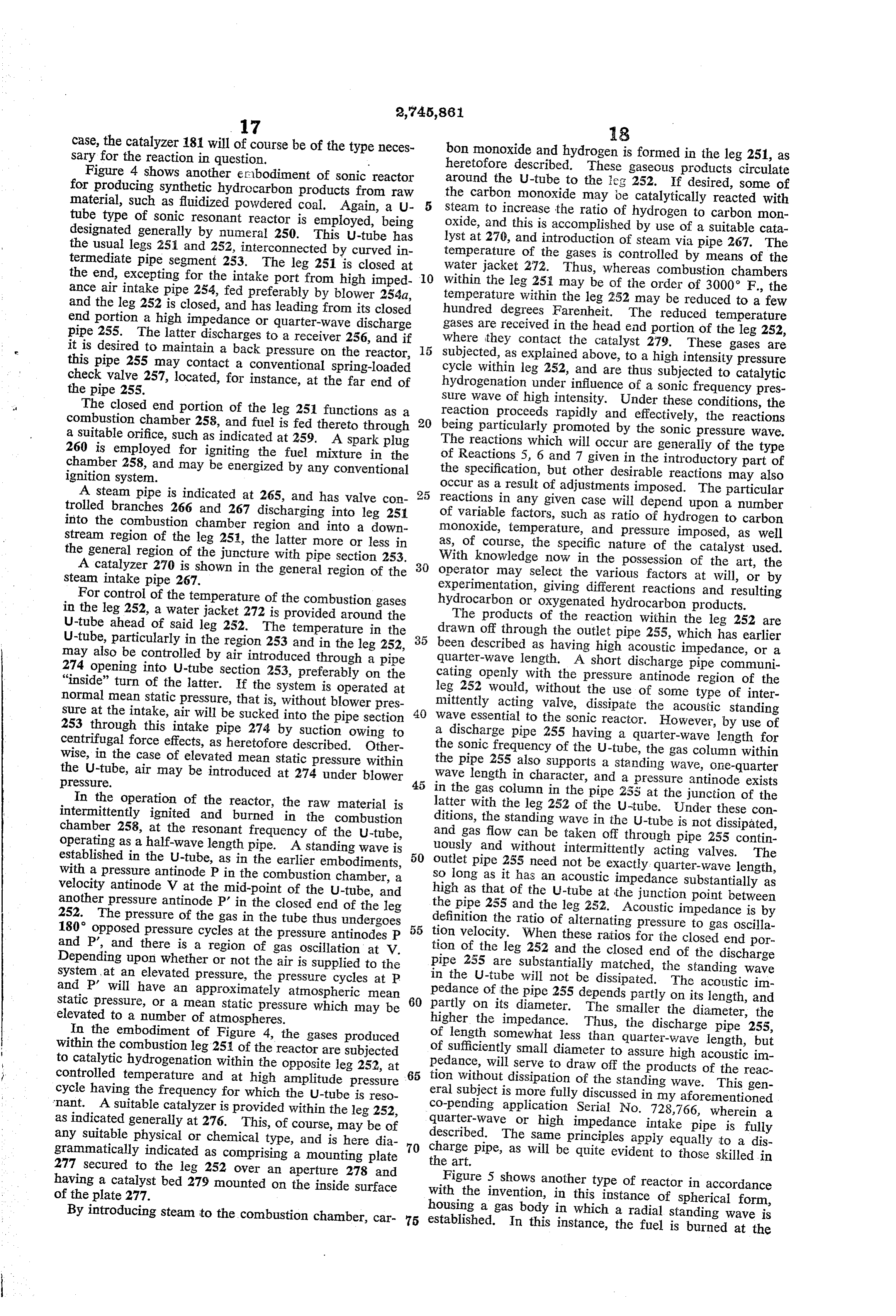
case, the catalyzer 181 will of course be of the type neces bon monoxide and hydrogen3.is formed in the leg 251, as sary for the reaction in question. heretofore described. These gaseous products circulate Figure 4 shows another erbodiment of sonic reactor around the U-tube to the leg 252. If desired, some of for producing synthetic hydrocarbon products from raw the carbon monoxide may be catalytically reacted with material, such as fluidized powdered coal. Again, a U steam to increase the ratio of hydrogen to carbon mon tube type of sonic resonant reactor is employed, being oxide, and this is accomplished by use of a suitable cata designated generally by numeral 250. This U-tube has lyst at 270, and introduction of steam via pipe 267. The the usual legs 251 and 252, interconnected by curved in temperature of the gases is controlled by means of the termediate pipe segment 253. The leg 251 is closed at water jacket 272. Thus, whereas combustion chambers the end, excepting for the intake port from high imped within the leg 2.5i may be of the order of 3000 F., the ance air intake pipe 254, fed preferably by blower 254a, temperature within the leg 252 may be reduced to a few and the leg 252 is closed, and has leading from its closed hundred degrees Farenheit. The reduced temperature end portion a high impedance or quarter-wave discharge gases pipe 255. The latter discharges to a receiver 256, and if whereare received in the head end portion of the leg 252, they contact the catalyst 279. These gases are it is desired to maintain a back pressure on the reactor, subjected, as explained above, to a high intensity pressure this pipe 255 may contact a conventional spring-loaded cycle within leg 252, and are thus subjected to catalytic check valve 257, located, for instance, at the far end of hydrogenation under influence of a Sonic frequency pres the pipe 255. sure wave of high intensity. Under these conditions, the The closed end portion of the leg 251 functions as a reaction proceeds rapidly and effectively, the reactions combustion chamber 258, and fuel is fed thereto through 20 being particularly promoted by the sonic pressure wave. a suitable orifice, such as indicated at 259. A spark plug The reactions which will occur are generally of the type 260 is employed for igniting the fuel mixture in the of Reactions 5, 6 and 7 given in the introductory part of chambersystem.
ignition 258, and may be energized by any conventional the specification, but other desirable reactions may also occur as a result of adjustments imposed. The particular
A steam pipe is indicated at 265, and has valve con 25 reactions in any given case will depend upon a number trolled branches 266 and 267 discharging into leg 25 of variable factors, such as ratio of hydrogen to carbon into the combustion chamber region and into a down monoxide, temperature, and pressure imposed, as well stream region of the leg 25, the latter more or less in as, of course, the specific nature of the catalyst used. the general region of the juncture with pipe section 253. With knowledge now in the possession of the art, the A catalyzer 270 is shown in the general region of the 30 operator may select the various factors at will, or by steam intake pipe 267. experimentation, giving different reactions and resulting For control of the temperature of the combustion gases hydrocarbon or oxygenated hydrocarbon products. in the leg 252, a water jacket 272 is provided around the The products of the reaction within the leg 252 are U-tube ahead of said leg 252. The temperature in the drawn of through the outlet pipe 255, which has earlier U-tube, particularly in the region 253 and in the leg 252, 35 been described as having high acoustic impedance, or a may also be controlled by air introduced through a pipe 274 opening into U-tube section 253, preferably on the cating openly length.
with the
A short discharge pipe communi pressure antinode region of the "inside' turn of the latter. If the system is operated at leg 252 would, without the use of some type of inter normal mean static pressure, that is, without blower pres mittently acting valve, dissipate the acoustic standing sure at the intake, air will be sucked into the pipe section 40 wave essential to the sonic reactor. However, by use of 253 through this intake pipe 274 by suction owing to a discharge pipe 255 having a quarter-wave length for centrifugal force effects, as heretofore described. Other the sonic frequency of the U-tube, the gas column within wise, in the case of elevated mean static pressure within the pipe 255 also supports a standing wave, one-quarter the U-tube, air may be introduced at 274 under blower pressure. 45 Wave length in character, and a pressure antinode exists in the gas column in the pipe 23S at the junction of the
In the operation of the reactor, the raw material is latter with the leg 252 of the U-tube. Under these con intermittently ignited and burned in the combustion ditions, the standing wave in the U-tube is not dissipated, chamber 258, at the resonant frequency of the U-tube, and gas flow can be taken off through pipe 255 contin operating as a half-wave length pipe. A standing wave is uously and without intermittently acting valves. The established in the U-tube, as in the earlier embodiments, 50 outlet pipe 255 need not be exactly quarter-wave length, with a pressure antinode P in the combustion chamber, a so long as it has an acoustic impedance substantially as velocity antinode V at the mid-point of the U-tube, and high as that of the U-tube at the junction point between another pressure antinode P' in the closed end of the leg the pipe 255 and the leg 252. Acoustic impedance is by 252. The pressure of the gas in the tube thus undergoes definition the ratio of alternating pressure to gas oscilla 180 opposed pressure cycles at the pressure antinodes P 55 tion velocity. When these ratios for the closed end por and P', and there is a region of gas oscillation at V. tion of the leg 252 and the closed end of the discharge Depending upon whether or not the air is supplied to the pipe 255 are Substantially matched, the standing wave system, at an elevated pressure, the pressure cycles at P and P’ will have an approximately atmospheric mean pedance of the pipe 255 depends partly The in the U-tube will not be dissipated. acoustic im on its length, and static pressure, or a mean static pressure which may be 60 partly on its diameter. The smaller the diameter, the elevated to a number of atmospheres. higher the impedance. Thus, the discharge pipe 255, In the embodiment of Figure 4, the gases produced of length somewhat less than quarter-wave length, but within the combustion leg 251 of the reactor are subjected of Sufficiently small diameter to assure high acoustic im to catalytic hydrogenation within the opposite leg 252, at pedance, will serve to draw off the products of the reac controlled temperature and at high amplitude pressure 65 tion without dissipation of the standing wave. This gen cycle having the frequency for which the U-tube is reso eral subject is more fully discussed in my aforementioned 'nant. A suitable catalyzer is provided within the leg 252, co-pending application Serial No. 728,766, wherein a as indicated generally at 276. This, of course, may be of quarter-wave or high impedance intake pipe is fully any suitable physical or chemical type, and is here dia described. The same principles apply equally to a dis grammatically indicated as comprising a mounting plate 70 the charge art.
pipe, as will be quite evident to those skilled in 277 secured to the leg 252 over an aperture 278 and having a catalyst bed 279 mounted on the inside surface Figure 5 shows another type of reactor in accordance of the plate 277. with the invention, in this instance of spherical form, By introducing steam to the combustion chamber, car housing a gas body in which a radial standing wave is 75 established. In this instance, the fuel is burned at the
Page 13
center of the spherical shell, and sends out radially and water by the time the velocity antinode region V is traveling compression waves, and these waves are re reached, there may still be regions closer to the point of flected by the inside surface of the sphere, to be returned combustion at which carbon monoxide predominates, and toward the source as a focus. A second charge of fuel the pipe 309 reaches into this region and takes off the is burned at the center, or focus, coincidentally with the desired product. - arrival of this reflected wave of compression, and a spher The other auxiliary equipment described in connection ical type of standing wave is thus established, with a first with employed other embodiments of the invention may easily be with the spherical form of apparatus of Fig pressure antinode P at the center, a second pressure an tinode P' at the reflecting boundary, and a velocity anti O for introducingas reagents ure 5. Thus, will be evident, pipes may be employed to various regions of the shell, node region V in space between the regions P and P. catalytic structures may be mounted therein, etc. As specifically shown in Figure 5, the spherical shell is The reactors and processes described herein are par indicated at 300, and an air supply pipe 301 extends in ticularly useful for carrying out reactions of the types wardly through this shell to support a short cylinder 302 at the center of the shell. The pipe 391 joins the cylinder 5 given hereinabove, such as for gasification of powdered and fluidized carbonaceous raw materials to produce 302 tangentially, so that air introduced through pipe 301 carbon monoxide, mixtures of carbon monoxide and spins within the cylinder 302. A fuel feed pipe 303 hydrogen, and synthetic hydrocarbon or oxygenated introduces fluidized powdered raw material, as coal, to products. They promote, accelerate, and shift the equilib the turbulent space inside the cylinder 302, and a spark rium of such reactions by reason of the high intensity plug 304 mounted in the cylinder 302 ignites the charge. Sonic pressure and velocity cycles maintained within the The pipe 301 is preferably a valveless, high impedance reaction regions of the apparatus. pipe, i. e., having an acoustic impedance as high as the As heretofore stated, the particular temperatures, pres center region of the gas body in the shell 300, and if it be desired to operate at an elevated mean pressure, a Sures, catalysts, and the various reagents used in the mak blower 306 may be employed to supply air under pres ing of synthetic hydrocarbons, are subject to wide varia tion to give different end products, as will be understood sure to pipe 301. Otherwise, the pipe 30 may have its by and will be within the skill of those versed in the art. entrance mouth open to atmosphere. Some indication of typical operating conditions will A discharge pipe 308 takes off gaseous products from nevertheless be given, though without intention of limiting velocity antinode region V, and another discharge pipe the scope of the invention.
309 is shown as positioned to take off products of com 30 The particular product obtainable by catalytic hydro bustion immediately adjacent the pressure antinode re genation of carbon monoxide at any temperature depends gion P. A third discharge pipe 319 takes off products partly upon hydrogen-carbon monoxide ratio, catalyst from the pressure antinode region P. The pipe 309, used and pressure, but, in general, it is known that straight connecting into the region P, should be sufficiently long chain hydrocarbons are obtained in the range 300 to have an acoustic impedance substantially as high as 500 F., alcohols in the range 575-750 F., isoparaffins that of the gas body in the region P; and the pipe 310 in the range 750-885 F., and aromatics in the range should be long enough to have an acoustic impedance as 885-930 F.
high as that in the region P. The useful operating pressures are not critical and The processes described hereinabove may be carried out in this different form of apparatus. Fuel charges 40 can range from atmospheric to several thousand pounds per square inch, depending largely upon the catalyst.
consisting of mixtures of powdered fuel, for example, Different reactions, of course, occur at optimum rate at powdered coal, and air are introduced periodically or different pressures, and some proceed best in a range as continuously, by way of fuel feed pipe 302, and air is supplied through air supply pipe 301, the amount of air high as from 4000 to 5000 pounds per square inch. As earlier explained, the standing sound wave main being controllable by means of butterfly valve 310. iained within the gas body or column has a varying pres To initiate operation, the spark plug 304 is energized sure cycle
at one region, the pressure antinode, and this and explodes the first fuel charge. This explosion sends a cycle diminishes to zero amplitude toward another region, spherical radially traveling wave of compression to the the velocity antinode. This pressure cycle swings above wall of the spherical shell 300. This wave is reflected back towards the source, and builds up a second pres 50 and below a mean pressure level, which may be close to atmospheric, or considerably elevated above atmospheric.
sure peak upon arriving back at P. This compression I have previously had reference to "mean static pressure,' peak results in an explosion of the fuel charge introduced in the interim, so that an augmented pressure peak is which term, strictly speaking, denotes the internal pres sure which would exist within the system in a quiescent produced, sending out another radially traveling wave of state, i. e., with no sound wave. For example, this mean compression. This cycle is then repeated at the resonant static pressure might be atmospheric pressure, if no frequency of the gas body in the spherical shell. It will be seen that a standing wave is established, having pres blower elevated is used for air supply; or it might be considerably using blower pressure, and a back-pressure hold.
sure antinodes P and P' and velocity antinode V, posi ing valve at the discharge. Mean operating pressure, with tioned as indicated in the drawings. the standing wave established, will in general somewhat Products of combustion may be drawn of through pipe 308, having an intake mouth located in the velocity 60 exceed mean static pressure at the pressure cycle regions, and will tend to be less than static at the velocity antinode antinode region of the sphere. Such a pipe need have regions. - no valve, unless it be desired to operate at an elevated The magnitude of the pressure swing above and below mean pressure, in which case a spring-loaded back pres sure valve (not shown) would be used in the pipe 308. 65 aStatic mean operating pressure increases with increased mean pressure. Thus, with a mean static pressure cf
Also shown are discharge pipes 309 and 350, taking one atmosphere, the positive pressure peak will easily products of combustion from a point closely adjacent reach 40 pounds per square inch, while with a mean static the combustion region, and from the outer pressure antinode region P', respectively, and such pipes, in order pressure of 200 pounds per square inch, the peak positive pressure can reach or somewhat exceed 500 pounds per to avoid loss of wave energy, are designed to have high square inch.
acoustic impedance, as earlier discussed. An advantage The catalytic hydrogenation of synthesis gases is in the use of the pipe 309 is that it may draw off products usually carried out at medium pressures, i. e., 75-220 of combustion from an inner region of the apparatus, pounds per square inch. According to my invention, this where the combustion may not be entirely completed. reaction may be carried out in a velocity antinode region For example, if, under any conditions of operation, the fuel charge tends to be largely burned to carbon dioxide 75 (Figure 3), where pressure is substantially static mean
Page 14
pressure, or in a pressure antinode region (Figure 4), powdered carbonaceous fuel such as coal and the like, where the mean pressure somewhat exceeds static mean, that comprises: periodically burning successive rich mix and large pressure swings are imposed. In the first case, ture charges of the powdered fuel and air within, and the static mean pressure is set to the desired operating at instants of peak positive pressure at, a pressure anti pressure, and the main value of the sound wave to the node region of a confined resonant half wavelength sonic reaction is evidently the high velocity of the oscillating gas column undergoing the pressure and velocity cycles gases scrubbed back and forth along the catalyst. In the of a standing sound wave maintained in said column by second case, the pressure swings up and down about the such burning, and drawing off the products of combustion operating mean. By establishing a mean static pressure of 80 pounds per square inch, I have a positive pressure 0 from said gas column.
3. The process of producing carbon monoxide from a peak approaching 220 pounds per square inch. The powdered carbonaceous fuel such as coal and the like, negative pressure half cycle will then drop the pressure that comprises: periodically burning successive rich mix to about 40 pounds per square inch, so that I have a ture charges of the powdered fuel and air within, and at resonant frequency pressure Swing covering the range instants of peak positive pressure at, each of the pres from 40–220 pounds per square inch. 5 sure antinode regions of a confined half wavelength sonic
The higher pressures favor the production of oxy gas column undergoing the pressure and velocity cycles genated compounds, and choice of proper temperature of and high pressure, together with the proper catalysts, Sucha standing burning, sound wave maintained in said column by and drawing off the products of combus provide conditions under which the isoparaffins can be obtained. For example, the latter reaction has been ob 20 tion4. from said gas column. The process of producing carbon monoxide from tained in known apparatus with a pressure of 4,400 a powdered carbonaceous fuel such as coal and the like, pounds per square inch. With the present process. (re that comprises: periodically burning successive rich mix acting in a pressure antinode Zone) the mean pressure ture charges of the powdered fuel and air within, and at may be lower, but the pressure swing will cover a sub stantial range. Thus, as an example, mean pressure 25 instants of peak positive pressure at, a pressure antinode region of a confined resonant half wavelength sonic gas may be 2,500 pounds per square inch, giving a pressure column undergoing the pressure and velocity cycles of a swing over the approximate range of 1,200-6,000 pounds standing sound wave, periodically burning mixtures of per square inch.
In general, my sonic process and reaction chamber positive hydrocarbon fuel and air within, and at instants of peak provide conditions under which any of the known reac 30 the gas column, pressure at, the other pressure antinode region of tions of the types herein referred to, namely, burning of all in such manner as to maintain said raw materials to produce CO, reacting with steam to Standing wave by such burning, and drawing off the prod produce hydrogen, catalytic hydrogenation of H and ucts of combustion from said gas column. CO, oxygenation, hydroforming, etc., can be promoted 5. The process of producing carbon monoxide from a and accelerated, and the equilibrium points of the dif 35 powdered carbonaceous fuel such as coal and the like, ferent reactions desirably shifted, owing to the high am that comprises: periodically burning successive rich mix plitude pressure and velocity cycling. Those having a ture charges of the powdered fuel and air within, and at knowledge of these reactions can, with the teachings given instants of peak positive pressure at, a pressure antinode herein, performany of them under the improved con region of a confined resonant gas body undergoing the ditions provided by the present invention. 40 pressure and velocity cycles of a standing sound wave It has been mentioned earlier that the present process maintained in said body by such burning, and drawing off consumes powdered coal at an unprecedented rate. The the products of combustion from said gas body. . . present process and apparatus has a corresponding high 6. The process of producing carbon monoxide from a through-put rate, giving high plant output. Under cer powdered carbonaceous fuel such as coal and the like, tain circumstances, this high through-put rate has inci 45 that comprises: periodically burning successive rich mix dental but important advantages. It is known, for ex ture charges of the powdered fuel and air within, and at ample, that high through-put rate favors the production instants of peak positive pressure at, a pressure antinode of oxygenated compounds. Also, high space velocity region of a confined resonant gas body undergoing the favors the production of olefins. pressure and velocity cycles of a standing sound wave The invention has now been described as embodied maintained in said body by such burning, and drawing off in several typical and illustrative embodiments and with 50 the products of combustion from- a velocity antinode reference to certain specific reactions. These embodi region of said gas body.
ments and specific reactions are to be considered as illus 7. The process of producing carbon monoxide from a trative and not limitative, however, and the invention is powdered charbonaceous fuel such as coal and the like, not deemed to be limited in scope excepting as expressed that comprises: periodically burning successive rich mix in the appended claims. It is also to be noted that, while 55 ture charges of the powdered fuel and air within, and I have shown several forms of physical apparatus, each at instants of peak positive pressure at, a pressure anti equipped with a selection of certain auxiliary apparatus, node region of a confined resonant gas body under such as air intake devices, feed pipes, product discharge de going the pressure and velocity cycles of a standing sound vices, valves, catalysts, etc., these various auxiliary de wave maintained in said body by such burning, and draw vices may each and all be used in connection with any 60 ing off the products of combustion from another pressure one or all of the main illustrative embodiments, as will antinode zone of said gas body. readily be apparent to those skilled in the art. 8. The process of producing carbon monoxide from a I claim: powdered carbonaceous fuel such as coal and the like, 1. The process of producing carbon monoxide from a that comprises: periodically burning successive rich mix powdered carbonaceous fuel such as coal and the like, 65 ture charges of the powdered fuel and air within, and at in that comprises: periodically burning successive rich mix stants of peak positive pressure at, a pressure antinode ture charges of the powdered fuel and air within, and at region of a confined resonant gas body undergoing the instants of peak positive pressure at, a pressure antinode pressure and velocity cycles of a standing sound wave region of a confined resonant gas column undergoing the pressure and velocity cycles of a standing sound wave 70 maintained off the in said body by such burning, and drawing products of combustion from a plurality of regions maintained in said column by such burning, and draw ingm.off the products of combustion from said gas col of9.saidThe standing wave.
process of producing carbon monoxide from a 2. The process of producing carbon monoxide from a 75 that powdered carbonaceous fuel such as coal and the like, comprises: periodically burning successive rich mix
Page 15
ture charges of the powdered fuel and air within, and at the products of the reaction from a velocity antinode instants of peak positive pressure at, a pressure antinode region of the gas column.
region of a confined resonant gas body undergoing the 16. The process of gasifying a carbonaceous combusti pressure and velocity cycles of a standing sound wave 5 successiveble raw material, that comprises: periodically burning maintained in said body by such burning, and drawing off air within, rich and mixture charges of the raw material and at instants of peak positive pressure at, the products of combustion from a position within said a pressure antinode region of a confined resonant gas gas body in the general region of said pressure antinode. column undergoing the pressure and velocity cycles of a 10. The process of producing carbon monoxide from a powdered carbonaceous fuel such as coal and the like, O standing burning, sound wave maintained in said column by such thereby producing carbon monoxide, withdraw that comprises: forming a fluidized stream of the pow ing gaseous products from the gas column from a point dered fuel and air, feeding said stream to a pressure spaced along said column from said pressure antinode, antinode region of a confined resonant gas body under so as to establish a longitudinal flow of said carbon going the pressure and velocity cycles of a standing wave, periodically burning the fluidized fuel sp introduced to monoxide monoxide along said gas column, whereby said carbon is subjected to the pressure and velocity oscilla said pressure antinode region in a deficiency of air at in tions of the standing sound wave maintained along the stants of peak positive pressure thereat, thereby driving said standing wave by the periodically released heat, and gas to column, and introducing reagents into said gas column react with said carbon monoxide during its longitudinal drawing off the resulting products of combustion from the travel along said gas column, and while it is being sub gas body.
11. The process of producing carbon monoxide from 20 jected to said pressure and velocity oscillations of said standing sound wave.
a powdered carbonaceous fuel such as coal and the like, 17. The process of gasifying a powdered solid carbona that comprises: periodically forming rich mixture charges ceous combustible raw material such as coal and the like, of the powdered fuel and air in the pressure antinode that comprises: periodically burning successive rich mix region of a resonant sonic reaction chamber, periodically 25 ture charges of the powdered raw material and air within, burning the fuel charges at said pressure antinode region and at instants of peak positive pressure at, a pressure at a resonant frequency of the chamber thereby driving antinode region of a confined resonant gas column under said standing wave by the periodically released heat, and going the pressure and velocity cycles of a standing sound drawing off products of the combustion from the chamber.
12. The process of producing carbon monoxide from a 30 wave maintained in said column by such burning, thereby producing carbon monoxide, withdrawing gaseous prod powdered carbonaceous fuel such as coal and the like, that comprises: periodically forming rich mixture charges ucts from the gas column from a point spaced along said column from said pressure antinode, so as to establish of the powdered fuel and air in the pressure antinode a longitudinal flow of said carbon monoxide along said region of a resonant sonic gas conduit in which a standing gas column, whereby said carbon monoxide is subjected sound wave can be established, burning the charges at to the pressure and velocity oscillations of the standing said pressure antinode region of the conduit at a reso 35 sound wave maintained along the gas column, and cata nant frequency of the conduit thereby establishing and lytically reacting the carbon monoxide with steam during driving said standing wave by the periodically released its longitudinal travel along said gas column, and while heat, and drawing off products of combustion from the it is being subjected to said pressure and velocity oscilla conduit. tions of said standing sound wave. 13. The process of gasifying a powdered solid carbona 40 18. The process of producing synthetic hydrocarbon ceous combustible raw material such as coal and the like, products from a powdered solid carbonaceous raw mate that comprises: periodically burning successive rich mix rial such as coal and the like, that comprises: periodically ture charges of the powdered raw material and air within, burning successive rich mixture charges of the powdered and at instants of peak pressure at, a pressure antinode 45 raw material and air within, and at instants of peak posi region of a confined resonant gas body undergoing the tive pressure at, a pressure antinode region of a confined pressure and velocity cycles of a standing sound wave resonant gas column undergoing the pressure and velocity maintained in said body by such burning, injecting steam cycles of a standing sound wave maintained in said column into the general region of said pressure antinode for re by Such burning, thereby producing carbon monoxide, action with the heated carbon of the raw material to pro establishing a flow of said carbon monoxide longitudinally duce carbon monoxide and hydrogen, and drawing off the along said gas column in a direction away from said pres products of the reaction from the gas body. Sure antinode region, reacting steam with heated carbon 14. The process of gasifying a powdered solid carbona in the gas column to produce hydrogen flowing along said ceous combustible raw material such as coal and the like, gas column in a mixture with said carbon monoxide, that comprises: periodically burning successive rich mix 55 effecting hydrogenation of the mixture of hydrogen and ture charges of the powdered raw material and air within, and at instants of peak pressure at, a pressure antinode carbon monoxide by contacting said mixture with a cata lyst at a region of said gas column which is subject to region of a confined resonant gas column undergoing the said standing sound wave, and withdrawing the products pressure and velocity cycles of a standing sound wave of hydrogenation from the gas column. of at least half-wave length maintained in said column 60 19. The process of producing synthetic hydrocarbon by such burning, injecting steam into the general region products from a powdered solid carbonaceous raw mate of said pressure antinode for reaction with the heated rial such as coal and the like, that comprises: periodically carbon of the raw material to produce carbon monoxide burning successive rich mixture charges of the powdered and hydrogen, and drawing off the products of the reac raw material and air within, and at instants of peak posi tion from the gas column.
15. The process of gasifying a powdered solid carbona 65 tive pressure at, a pressure antinode region of a confined resonant gas column undergoing the pressure and velocity ceous combustible raw material such as coal and the like, cycles of a standing sound wave maintained in said column that comprises: periodically burning successive rich mix by such burning, thereby producing carbon monoxide, es ture charges of the powdered raw material and air within, tablishing a flow of said carbon monoxide longitudinally and at instants of peak pressure at, a pressure antinode region of a confined resonant gas column undergoing the 70 along sure said gas column in a direction away from said pres antinode region, reacting steam with heated carbon pressure and velocity cycles of a standing sound wave in the gas column to produce hydrogen flowing along said maintained in said column by such burning, injecting gas column in a mixture with said carbon monoxide, ef. steam into the general region of said pressure antinode fecting hydrogenation of the mixture of hydrogen, and for reaction with the heated carbon of the raw material to produce carbon monoxide and hydrogen, and drawing off carbon monoxide by contacting said mixture with a cata
Page 16
lyst within a velocity antinode region of said gas column longitudinally along said gas column in a direction away whereby the gases undergo a substantial velocity oscilla tion cycle, and withdrawing the products of hydrogena from said pressure antinode region, mixing hydrogen with said carbon monoxide, effecting hydrogenation of the tion from the gas column. mixture of hydrogen and carbon monoxide by contacting 20. The process of producing synthetic hydrocarbon products from a powdered solid carbonaceous raw mate said mixture with a catalyst within a volecity antinode region of said gas. column whereby the gases undergo a rial such as coal and the like, that comprises: periodically substantial velocity oscillation cycle, and drawing the burning successive rich mixture charges of the powdered products of hydrogenation from the gas column. raw material and air within, and at instants of peak posi 24. The process of producing synthetic hydrocarbon tive pressure at, a pressure antinode region of a confined O products resonant gas column undergoing the pressure and velocity terial suchfrom as a powdered solid carbonaceous raw ma coal and the like, that comprises: periodi cycles of a standing sound wave maintained in said column cally burning successive rich mixture charges of the by such burning, thereby producing carbon monoxide, powdered raw material and air within, and at instants of establishing a flow of said carbon monoxide longitudinally peak positive pressure at, a pressure antiode region of a along said gas column in a direction away from said pres 15 confined resonant gas column undergoing the pressure Sure antinode region, reacting steam with heated carbon and velocity cycles of a standing sound wave maintained in the gas column to produce hydrogen flowing along said in gas column in a mixture with said carbon monoxide, ef bonsaid column by such burning, thereby producing car fecting hydrogenation of the mixture of hydrogen and oxidemonoxide, establishing a flow of said carbon mon longitudinally along said gas column in a direction carbon monoxide by contacting said mixture with a cata 20. away from said pressure antiode region, mixing hydrogen lyst within a second pressure antinode region of said gas with said carbon monoxide, effecting hydrogenation of column whereby the gases undergo a pressure oscillation the mixture of hydrogen and carbon monoxide by con cycle, and withdrawing the products of hydrogenation tacting said mixture with a catalyst within a second pres from the gas column.
21. The process of producing synthetic hydrocarbon 25 gases sure antinode region of said gas column whereby the products from a powdered solid carbonaceous raw mate ing theundergo a pressure oscillation cycle, and withdraw products of hydrogenation from the gas column.
rial such as coal and the like, that comprises: periodically burning Successive rich mixture charges of the powdered duit25.having In a sonic burner, the combination of: a gas con a resonant frequency at which a longitudinal raw material and air within, and at instants of peak posi standing sound wave can be set up therein, with at least tive pressure at, a pressure antinode region of a confined 30 two pressure antinode resonant gas column undergoing the pressure and velocity antinode region, said regions conduit and an intervening velocity having a substantial lon cycles of a standing sound wave maintained in said gitudinal bend in the region of said velocity antinode, column by such burning, thereby producing carbon mon whereby centrifugal force effects are exerted upon prod oxide, establishing a flow of said carbon monoxide lon gitudinally along said gas column in a direction away 35 ucts traveling longitudinally through said velocity anti node regions and past said bend, means for introducing from Said pressure antinode region, reacting steam with fuel and air mixtures into the pressure antinode region in heated carbon in the gas column to produce hydrogen one end portion of said conduit and for burning said mix flowing along said gas column in a mixture with said car ture at said pressure antinode region, so as to set up bon monoxide, cooling said mixture of hydrogen and car periodic compression and consequent fuel combustion bon monoxide to a temperature at which said gases can 40 at the resonant frequency be catalytically hydrogenated, effecting hydrogenation of lishing and maintaining saidof standing the conduit, thereby estab wave, an ash trap the mixture of hydrogen and carbon monoxide by con communicating with said conduit in the region of said tacting the cooled mixture of hydrogen and carbon mon longitudinal bend and on the outside of said bend, so as oxide with a catalyst at a region of said gas column which to collect ash particles thrown outwardly from the gas is subject to said standing sound wave, and withdrawing 45 stream in the conduit by centrifugal force upon travers the products of hydrogenation from the gas column.
22. The process of producing synthetic hydrocarbon ing said longitudinal bend, and means for withdrawing products from a powdered solid carbonaceous raw ma gaseous products of combustion from another region of terial such as coal and the like, that comprises: pe said conduit.
riodically burning successive rich mixture charges of the 26. In a sonic burner, the combination of: a gas con powdered raw material and air within, and at instants of 50 duit having a resonant frequency at which a longitudinal peak positive pressure at, a pressure antinode region of a standing sound wave can be set up therein, with at least confined resonant gas column undergoing the pressure two pressure antinode regions and an intervening velocity and velocity cycles of a standing sound wave maintained antinode region, said conduit having a substantial lon in said column by such burning, thereby producing car 55 gitudinal bend in the region of said velocity antinode, bon monoxide, establishing a flow of said carbon mon whereby centrifugal force effects are exerted upon prod oxide longitudinally along said gas column in a direction ucts traveling longitudinally through said velocity anti away from said pressure antiode region, mixing hydrogen node regions and past said bend, means for introducing with said carbon monoxide, effecting hydrogenation of the fuel and air mixtures into the pressure antinode region mixture of hydrogen and carbon monoxide by contacting 60 in one end portion of said conduit and for burning said said mixture with a catalyst at a region of said gas column mixture at said pressure antiode region, so as to set up which is subject to said standing sound wave, and with periodic compression and consequent fuel combustion at drawing the products of hydrogenation from the gas the resonant frequency of the conduit, thereby establish column. ing and maintaining said standing wave, an ash trap com 23. The process of producing synthetic hydrocarbon 65 municating with said conduit in the region of said lon products from a powdered solid carbonaceous raw mate gitudinal bend and on the outside of said bend, so as to rial such as coal and the like, that comprises: periodically collect ash particles thrown outwardly from the gas burning successive rich mixture charges of the powdered stream in the conduit by centrifugal force upon travers raw material and air within, and at instants of peak posi ing said longitudinal bend, and means for withdrawing tive pressure at, a pressure antinode region of a con 70 gaseous products of combustion from the velocity anti fined resonant gas column undergoing the pressure and node region of the conduit from a point therein spaced velocity cycles of a standing sound wave maintained in inward from the plane of communication between the said column by such burning, thereby producing carbon conduit and ash trap.
monoxide, establishing a flow of said carbon monoxide 5 (References on following page)
Page 17
References Cited in the file of this patent 2,388,348 , Stimson ---------------- Nov. 6, 1945
UNITED STATES PATENTS 2,690,960 Kistiakowsky et al. ------- Oct. 5, 1954 1,860,138 Cross ---------------- May 24, 1932 FOREIGN PATENTS 2,087,391 Toulmin, Jr. ------------ July 20, 1937 5 REIGN - 2,347,682 Gunness ---------------- May 2, 1944 823,231 France ---------------- Oct. 11, 1937

Provenance
- Collection
- Cited prior art
- Original PDF
- patentimages.storage.googleapis.com →
- Filed
- 1952-08-11
- Pages
- 17
- Method
- pdftotext (the PDF's own text layer) + pdftoppm 300dpi page scans
- Source
- Google Patents bibliographic record
- Granted
- 1956-05-15
- Inventors
- Jr Albert G Bodine
- Transcribed from
- patentimages.storage.googleapis.com →