patent · US3952519
Heat transfer system employing supercooled fluids
27 April 1976
Page 1 — bibliographic record
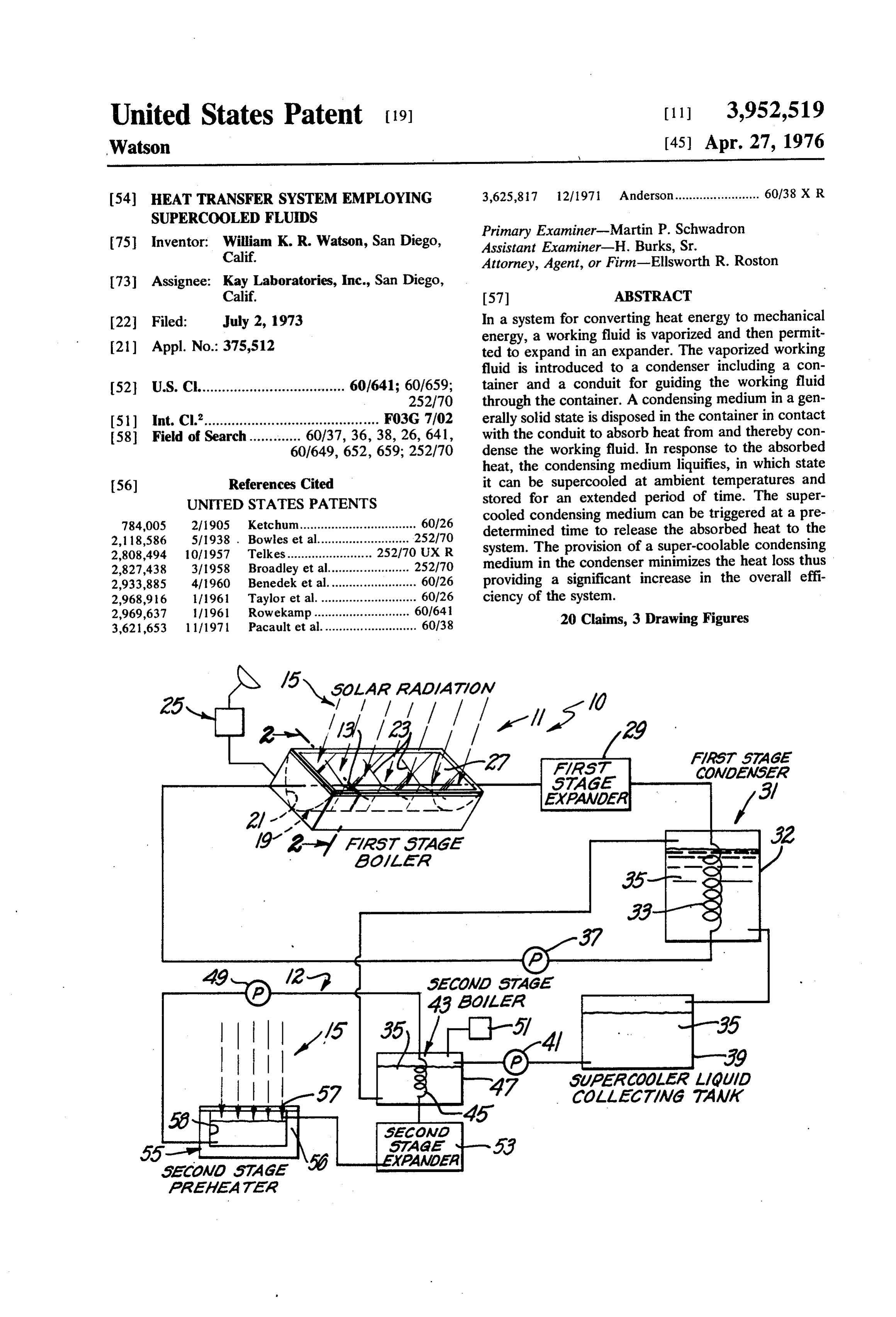
United States Patent (19) 11, 3,952,519 Watson (45) Apr. 27, 1976 (54) HEAT TRANSFER SYSTEM EMPLOYING 3,625,817 12/1971 Anderson........................ 60/38 X R
SUPERCOOLED FLUIDS
Primary Examiner-Martin P. Schwadron 75 Inventor: William K. R. Watson, San Diego, Assistant Examiner-H. Burks, Sr. Calif. Attorney, Agent, or Firm-Ellsworth R. Roston 73 Assignee: Kay Laboratories, Inc., San Diego,
Calif. 57 ABSTRACT 22 Filed: July 2, 1973 In a system for converting heat energy to mechanical energy, a working fluid is vaporized and then permit 21 ) Appl. No.: 375,512 ted to expand in an expander. The vaporized working fluid is introduced to a condenser including a con 52 U.S. C. .................................... 60/641; 60/659; tainer and a conduit for guiding the working fluid 252/70 through the container. A condensing medium in a gen 51) int. C.’............................................ F03G 7/02 erally solid state is disposed in the container in contact 58) Field of Search............. 60/37, 36, 38, 26, 641, with the conduit to absorb heat from and thereby con 60/649, 652, 659; 252/70 dense the working fluid. In response to the absorbed heat, the condensing medium liquifies, in which state 56 References Cited it can be supercooled at ambient temperatures and UNITED STATES PATENTS stored for an extended period of time. The super 784,005 2/1905 Ketchum................................. 60/26 cooled condensing medium can be triggered at a pre determined time to release the absorbed heat to the 2,118,586 5/1938 . Bowles et al.......................... 252/70 2,808,494 10/1957 Telkes........................ 252 to Ux R system. The provision of a super-coolable condensing 2,827,438 3/1958 Broadley et al....................... 252/70 medium in the condenser minimizes the heat loss thus 2,933,885 4/1960 Benedek et al......................... 60/26 providing a significant increase in the overall effi 2,968,916 1/1961 Taylor et al............................ 60/26 ciency of the system.
2,969,637 /1961 Rowekamp........................... 60/641 o 3,621,653 l l 11971 Pacault et al........................... 60/38 20 Claims, 3 Drawing Figures
COAMAWSAA
AAAAWOAA
YAMAA
Page 2
Drawing sheet — no readable text.
Page 3
course during the nighttime no radiant energy is re
HEAT TRANSFER SYSTEM EMPLOYING ceived from the sun, but even during the daytime a SUPERCOOLED FLUIDS considerable portion of the solar radiation may be in
BACKGROUND OF THE INVENTION
tercepted by clouds and haze. These factors have re duced the reliability of solar radiation as a source of 1. Field of the Invention heat.
This invention relates generally to apparatus for con To provide for these “rainy days' it has been desir densing a vaporized fluid and more specifically to the able to store energy in some form. It is known that use of such an apparatus in a solar energy converter. 10 energy in an electrical form can be stored in batteries. 2. Description of the Prior Art However, the cost of batteries having a capacity suffi Most apparatus providing a source of mechanical or cient to store a large amount of electrical energy has electrical power rely upon some source of heatenergy. been prohibitive. Furthermore, batteries have had an This heat energy typically results from the combustion internal resistance which gradually dissipates the stored of fuels such as oil, gas, coal and gasoline. In some 15 energy. As a consequence, batteries have not been systems, nuclear materials have undergone fission to capable of storing electrical energy for significant pe provide the heat energy. riods of time.
The heat provided by these sources of energy has It is known that the dissipation of heat energy from been converted into either electricity or mechanical an object can be reduced if the object is thermally work, unfortunately with tremendous inefficiency. The 20 insulated. For example, hot fluids have been disposed inefficiency has occurred as a result of the loss from the in vacuum bottles to inhibit the transfer of heat from system of a very large portion of the heat provided by the enclosed fluid through the walls of the bottle. These the source of energy. This lost heat has not been avail vacuum bottles as well known to be ineffectual for able for conversion into either electrical or mechanical extended periods of time. This would make such insu work. By way of example it will be noted that internal 25 lating means inapplicable to the present invention for combustion engines typically have an efficiency of the long term storage of thermal energy. Other insulat 22%, diesel engines have an efficiency of approxi ing means such as that used to lag pipes would be simi mately 40%, and nuclear or conventional power sta larly undesirable for storing heat energy over an ex tions have an efficiency of approximately 50%. tended period of time.
Electrical power stations are typical of those sources 30 SUMMARY OF THE ENVENTION of power which rely upon a source of heat energy. In these power stations, the heat is used to vaporize a In accordance with the present invention, a storage working fluid, such as water, to provide steam having a means such as a condenser is provided which has char high temperature and pressure. The steam is intro acteristics for storing energy in the form of heat. When duced to an expander, such as a stream engine or tur 35 used in a power system, this storage means or con bine, wherein the steam expands initially at substan denser significantly reduces the amount of energy lost tially constant temperature, and subsequently at sub to the environment. Instead, the stored energy is re stantially constant entropy. This expansion provides tained in the system, so that substantially 100% of the mechanical work and additionally reduces the temper heat energy provided by the heat source is ultimately ature and pressure of the steam. converted into power. As a practical matter, for a given In order to pump the working fluid back to the heat 40 power output, a heat source may use approximately source, the exhaust steam is introduced into a con one half the quantity of fuel used by prior systems In a denser where it is cooled to a liquid state. This conden solar energy converter, only about one-half the solar sation is typically accomplished with vast condensing radiation of the present system is needed for a given towers or the use of a relatively cold condensing me 45 power output.
dium. The condensing medium has typically included Of significant advantage is the fact that the heat en water which has been provided by a source such as a ergy in the present condenser or storage means can be lake, river or ocean. After passing through the con stored for a substantially indefinite period of time. This denser, the heated condensing medium has been re stored energy can be subsequently released to provide turned to the cooling source. It can be appreciated that a source of heat when the radiant energy of the sun is this heat absorbed by the condensing medium has been 50 no longer available. Heat continues to be available lost as far as its conversion to power is concerned. even when the rays of the sun are blocked so that the Particularly disturbing has been the fact that as much primary deficiency of solar energy converters of the energy has been lost in heating the condensing medium prior art is overcome by the present invention. as has been provided by the engine or turbine in the 55 In the storage means or condenser of the present form of electrical or mechanical power. invention, the condensing medium includes a first Some energy converters have relied upon solar radia chemical having a particular melting temperature and tion to heat the working fluid. Solar radiation is a pre characteristics for maintaining a relatively fluid stage at ferred source of energy for several reasons. First, the temperatures below the particular melting tempera quantity of energy available is generally unlimited. ture. Under these conditions, the chemical is said to be Additionally, the solar energy is relatively powerful, 60 supercooled. This first chemical can be disposed in the providing approximately one horsepower per square converter in a generally solid state so that when heat is yard of surface when the rays of the sun are received absorbed from the working fluid to condense or other normal to the surface. Furthermore, solar radiation is wise transfer heat from the working fluid, the chemical "free' when it is available. is heated above its particular melting temperature. This The questionable availability of solar radiation is 65 provides the first chemical with a generally fluid state. perhaps the primary deficiency of such a solar energy The fluid chemical is then allowed to drain from the converter. The sun cannot be relied upon to shine con converter into a tank where it can be stored for a sub tinuously upon any particular area of the earth. Of stantially indefinite period of time. In the tank, the
Page 4
chemical supercools to maintain the generally fluid referred to as the point of focus. The conductor 13 is state even attemperatures below the particular melting preferably disposed to pass through this point of focus temperature. to receive the concentrated solar heat energy. At a time when the radiant energy of the sun cannot The reflector 19 may be longitudinal in configuration be received to provide a source of heat, a particular 5 and the reflecting surface 21 may define a parabola in choice of working fluid can be heated by the first super axial cross section as shown in FIG. 2. In such an em cooled chemical. For example the working fluid and bodiment each axial cross section will provide a point the first supercooled chemical can be separated in a of focus and collectively the points of focus will define heat exchanger such as a boiler. Then a triggering a line of focus along which the conductor 13 is prefer means, such as a second chemical, can be introduced to 10 ably disposed. As the rays 15 of the sun strike the re the first chemical to trigger the crystallization of the flecting surface 21 of the reflector 19, they will be first chemical. This crystallization will occur at the reflected to converge on the conductor 13; the first particular melting temperature of the first chemical working fluid in the conductor 13 will be heated by this which will be greater than the boiling point of the work concentrated solar energy.
ing fluid which in turn is higher than the ambient tem- 15 The conductor 13 can be held in its preferred posi perature. In this manner the heat energy stored in the tion along the line of focus by plurality of wires 23 first chemical can be released to the working fluid in which can be attached at one of their ends to the pipe the boiler to heat and thereby vaporize the working 13 and at the other of their ends to the reflector 19. fluid and drive the expander. The conductor 13 may be coated, at least in proximity In a particular embodiment, a second working fluid 20 to the reflector 19, with a material such as black paint such as Freon “11” may be used in the heat exchanger. having a high emissivity. This coating will enhance the and a second expander responsive to the Freon vapor absorption of heat by the conductor 13. In a preferred can provide the power output of the system. A particu embodiment the reflector 19 is formed from an alumi larly desirable first chemical is that provided by sodium num sheet and the surface 21 is polished to enhance the acetate which has characteristics for crystallizing to 25 reflection of the rays 15. . . . . ." release 42 calories per gram at a particular melting To inhibit the loss of heat from the conductor 13 by temperature of 58°C. This first chemical is particularly convection, it may be desirable to inhibit the flow of air desirable for use with the Freon '1 1' which has a boil around the conductor 13. In a preferred embodiment, ing point of approximately 24 C. the frame 17 defines an enclosure with a sheet 27 These and other features and advantages of the pre- 30 which faces the surface 21. The sheet 27 may be either sent invention will be more apparent with a description rigid or flexible, but it is preferably transparent to per of preferred embodiments discussed with reference to mit the rays 15 to pass through the sheet 27 to the the associated drawings. reflecting surface 21. In a preferred embodiment, the DESCRIPTION OF THE DRAWINGS 35 sheet 27 is formed from a transparent plastic material. In an embodiment of the present invention which
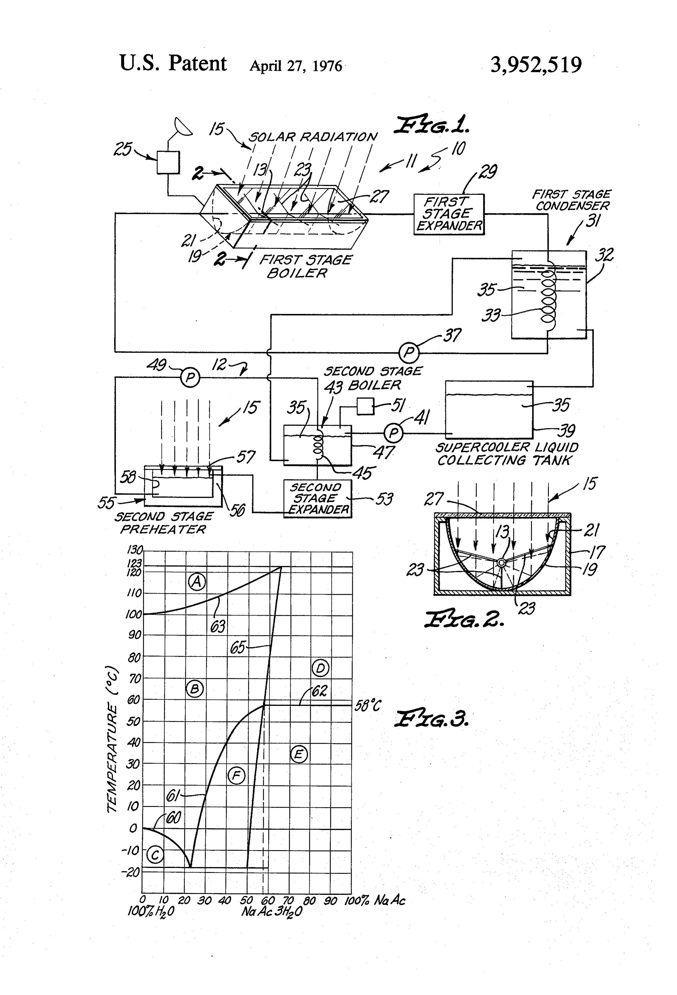
FIG. 1 is a schematic diagram of a solar energy con includes a solar heat source 11, it is desirable that the verter including one embodiment of the condenser of reflector 19 be positioned so that the pipe 13 is sub the present invention; stantially perpendicular to the rays 15 of the sun. Since FIG. 2 is an end elevation view of a reflector for the sun rotates with respect to the surface of the earth, conveying solar radiation to provide a source of heat, 40 a tracking means, shown generally at 25 in FIG. 1, can and be provided to track the sun and rotate the reflector 19 FIG. 3 is a graph illustrating the temperature and accordingly. i is , : . .
phase characteristics of a condensing medium adapted In a preferred embodiment of a solar heat source 11, for use in the condenser of the present invention. the reflector 19 can be of a size sufficient to receive the 45 rays 15 of the sun which would otherwise fall on ap
DESCRIPTION OF THE PREFERRED
EMBODIMENTS proximately two square yards of the surface of the earth. When the rays 15 pass normal to the atmosphere
An energy converter is illustrated in FIG. 1 to include and perpendicular to the conductor 13 at the line of a first stage 10 and a second stage 12. In the first stage focus, a reflector 19 of this size will develop approxi 10, a heat source 11 or boiler provides heat for vaporiz- 50 mately two horsepower of heat energy. ing a first working fluid or for heating a liquid which is In this particular embodiment, the first working fluid typically guided by a conductor 13 through the heat may comprise water having a vaporizing temperature source 1. The heat source 11 can be any of those of 100°C. The water in the conductor 13 will enter the noted in the prior art to derive heat from the combus heat source 11 at a temperature of approximately 58 tion of oil, gasoline, coal or gas. The heat source 11 55 C. It will exit the heat source 11 at a temperature of may also be of the type providing heat from the break approximately 158 C. and a pressure such as 85 lbs. ing up into fission fragments of nuclear materials such per square inch. At this high pressure and temperature, as uranium. In the particular embodiment illustrated, the water at the output of the heat source 11 will have however, the heat source 1 derives heat from the a vapor state as it passes to an expander 29. It will be radiant energy of the sun which is characterized by the 60 appreciated that the temperature of the water can be rays 15. heated to a temperature less than that producing vapor As illustrated in FIGS. and 2, this solar heat source ization of the water. ... " . . . " 11 will typically include a frame 17 providing structural The expander 29 will typically be a steam engine or support for a reflector 19. The reflector 19 has a re turbine providing a source of mechanical power. in the flecting surface 21 with characteristics for receiving the 65 expander 29, the steam will initially expand at a sub essentially parallel rays 15 of the sun and reflecting the stantially constant temperature and pressure. A further rays 15 so that in a particular cross section of the re adiabatic expansion of the steam in the expander 29 flector 19, the rays 15 converge at a point, typically will decrease the temperature of the steam to substan
Page 5
tially that of the expander, 29. The pressure of the temperature of its melting point. During this crystalliza steam will also decrease to substantially atmospheric tion, the heat absorbed by the chemical to achieve the pressure. Even under these conditions, the water will supercooled state is released at the substantially con typically maintain the vapor state. . . . . . . . . stant temperature of its melting point. Since this melt As is well known in the state of the art, in order to ing point is higher than the temperature at which the reduce the volume and facilitate the pumping of the supercooled chemical is stored, the chemical becomes first working fluid, it is desirable that the steam from a source of heat when triggered. These characteristics the expander 29 can be condensed to transfer heat or of supercoolable chemicals are explained in greater that the heat from the heated water can be cooled to detail in copending application Serial Number 357,817 transfer heat. Therefore, in the present invention, the 10 which was filed in the Patent Office on May 7, 1973, steam from the expander: 29 is conducted through a and which is assigned of record to the assignee of re condenser 31. The condenser 31 can be substantially cord of the present application.
any heat exchanger providing for the separation of first A supercoolable chemical which is particularly desir and second materials between which the heat is to be 15 able for use with a first working fluid of water is sodium exchanged. Thus, is a preferred embodiment, the con acetate trihydrate which has a melting temperature of denser is provided with a coil 33, which conducts the approximately 58°C. The sodium acetate trihydrate is first working fluid, such as steam, through a container advantageous to the present invention not only due to 32. A condensing medium. 35 is disposed within the its desirable melting temperature but also because of its container 32 in substantial contact with the outer sur desirable phase characteristics. In FIG. 3, a graph is face of the coil 33. The condensing medium 35 absorbs 20 provided which shows the melting temperatures and heat from the steam so that the water of the first work phase of a compound including sodium acetate and ing fluid is condensed. In this liquid state, the water can water. On this graph, the lines 60 and 61 show the be induced by a pump.37 to flow back to the heat melting point of the compound for various percentages source 11 to complete the energy, cycle. It will be ap 25 by weight of the anhydrous sodium acetate in the wa preciated that other heat transfer means than. the con ter. It will be noted that with zero percent sodium ace denser 31 can be used to transfer, heat, particularly tate, corresponding to 100% water, the compound has when the medium transferring heat constitutes aheated a melting point of 0°C., the melting point of water. As liquid rather than a vapor. . . . . . . . . . the percentage of sodium acetate in the compound is Of course, chemicals other than water, may be used 30 theincreased to approximately 23%, the melting point of for the first working fluid and some of these chemicals compound drops along a line 60 to a temperature of may have a boiling point lower than the ambient tem approximately -18 C. As the percentage of sodium perature. Under these circumstances it may be desir acetate is further increased to approximately 60%, the able to pressurize the condenser 31 to raise the boiling melting point of the compound rises along a line 61 to point of the first working fluid. . .. . approximately 58 C., the melting temperature of so The condensing medium 35 is preferably introduced 35 dium acetate trihydrate. This melting temperature of to the condenser 31 in a generally solid state character 58 C. is maintained even with further increases in the ized by substantial solid portions, but sufficient fluid percentage of the sodium acetate in the compound as portions to facilitate pumping of the condensing me shown by a constant temperature line 62. 1. dium 35. In this generally solid state, the condensing 40 Superimposed upon this graph is a phase diagram medium 35 will have a temperature below, its particular including a generally horizontal line 63 and a generally melting temperature. : . . . . . . .. . vertical line 65. These lines 63 and 65 together with the As previously discussed, the condensing media of the lines 60, 61 and 64 separate areas which are designated past have typically included cool water which has been in FIG.3 by the encircled capital letters A through F. In pumped from a lake, river, or ocean to condense the these areas A-F the compound has a particular phase first working fluid. After the heat from the working 45 which is dependent upon both the percentage of so fluid has been absorbed, the condensing medium and dium acetate in the compound and the temperature of , the absorbed heat have been returned to the water the compound. For example, above the line 63, in the area designated by the encircled A, the compound source. Since approximately as much heat has been returned to the water source as has been converted to consists of anhydrous sodium acetate and water vapor. mechanical energy by the expander, these systems. of 50 In the area designated by the encircled D to the right of the prior art had overall thermodynamic efficiencies of line. 65 and above the line 62, the compound includes less than 50%. is . . . . . . . . . . anhydrous sodium acetate and water in a liquid, brine The condensing medium 35 of the present invention type of phase. In the area B, defined by the lines 60, 61, also absorbs heat from the first working fluid; however 55 63 and 65, the compound has a temperature greater this condensing medium 35 is retained so that the ab than that of its melting point, and a liquid phase. At sorbed heat can be subsequently used in the system. As temperatures below the melting point of the compound a result, the overall efficiency of the present energy. in the area C, below the line 60, the sodium acetate in converter approaches 100% when both mechanical the compound has a liquid phase and the water in the compound has a solid phase.
output and heat retention are considered. . .
Supercoolable chemicals are particularly. desirable 60 Of particular interest in the present invention is the for use as the condensing medium. 35 since they each phase of the compound attemperatures below its melt have a particular melting temperature and characteris ing point and in proximity to the line 65. In the area E tics for maintaining a liquid state for extended periods to the right of the line 65 and below the line 62, the of time even attemperatures below the particular melt 65 compound in a supercooled state forms sodium acetate ing temperature. When such a chemical, it is in... the trihydrate with a precipitate of anhydrous sodium ace liquid state below its melting temperature, it is said to tate. This precipitate is configured in a multiplicity of be supercooled. In the supercooled state, the chemical - flakes which reinforce the crystals of sodium acetate can be triggered at any time to crystallize at the higher trihydrate when the compound is triggered. As a result
Page 6
of this reinforcement, the compound in this area E sodium acetate trihydrate form nucleation centers crystallizes to form a rigid block. This rigid form is about which the condensing medium forms one of a undesirable in the present invention wherein the con multiplicity of crystals. The characteristics of this par densing medium 35 preferably crystallizes in a state ticular triggering means are explained in greater detail which facilitates the pumping of the medium 35. in copending application Ser. No. 357,817, filed May 7, It will be noted that to the left of the line 65 and 1975 assigned to the assignee of the present applica below the line 61 in the area F, the compound in the tion.
supercooled state forms sodium acetate trihydrate and The crystallization of the supercooled condensing water in a liquid state. When this compound is trig medium 35 will occur at the substantially constant gered, the sodium acetate trihydrate forms a multiplic O temperature of its melting point. If the second working ity of crystals having a particulate configuration. The fluid flowing through the coil 45 has a vaporizing tem relative movement of the crystals is enhanced by the perature lower than the melting temperature of the lubrication resulting from the excess water in the com condensing medium 35, the second working fluid will pound. Thus, this phase of the compound is particularly vaporize at a high temperature and pressure as the desirable for use in the present invention since it crys 5 condensing medium 35 crystallizes. This high pressure tallizes in the generally solid configuration which facili second working fluid can be introduced to an expander tates the pumping of the crystallized medium 35. This 53 such as a turbine. In the expander 53, the second desirable phase can be provided by the compound working fluid initially expands at a substantially con including approximately 53% of the anhydrous sodium stant temperature and pressure and then further ex acetate. This particular compound has a melting tem 20 pands at a substantially constant entropy to a lower perature of approximately 56°C. temperature and pressure. This lower temperature may In the condenser 31 as heat is absorbed from the first be below the vaporizing temperature of the second working fluid, the temperature of the condensing me working fluid in which case the second working fluid dium 35 rises above its melting temperature to provide will condense to a liquid state in the expander 53. It will the medium 35 with a liquid state. In this liquid state, 25 be appreciated that the second working fluid may be the condensing medium 35 can be permitted to drain heated to a temperature above its normal temperature from the condenser 31 into a collecting tank 39. Even but below any vaporizing temperature without depart though the collecting tank 39 will typically be exposed ing from the scope of the invention. to an ambient temperature, the condensing medium 35 As the condensing medium 35 crystallizes, it prefer will supercool to maintain its liquid state even at a 30 ably achieves the generally solid state as previously temperature below its melting point. defined. In this state, the crystallized condensing me One of the major problems associated with solar dium 35 can be induced to flow from the boiler 43 back energy converters of the past has been the fact that the to the condenser 31 by the pump 41. The condensing rays 15 of the sun are not available during the night and medium 35 can be retained in the condenser 31 until may even be blocked by clouds or haze during the day. 35 the daylight hours provide the radiant energy needed to Under these circumstances, the reflector 19 cannot heat the first working fluid and drive the expander 29. function as a source of heat. It can be appreciated that the second working fluid In the present invention, the heat which was ab can be pumped directly from the expander 53 into the sorbed by the condensing medium 35 when solar en 40 boiler 43. However, the temperature of the second ergy was available is retained as latent heat in the su working fluid at the output of the expander 53 will percooled chemical in the collecting tank 39. When the typically be the ambient temperature at the time the reflector 19 can no longer function as a heat source, boiler 43 is in operation. Since this will typically be the the latent heat in the supercooled condensing medium nighttime, the second working fluid at the output of the 35 can be converted into mechanical or electrical en expander 53 will be exposed to an ambient temperature ergy by the second stage 12. in the second state 12, a 45 which is considerably cooler than the daytime ambient pump 41 induces the supercooled medium 35 to flow temperature. If this relatively cold fluid were returned from the tank 39 into a heat exchanger such as a boiler directly to the boiler 43, a substantial quantity of heat 43. The boiler 43 typically includes a coil 45 enclosed would be needed in the boiler 43 to provide the second by a container 47. In a particular embodiment, a sec working fluid with the desired temperature and pres ond working fluid can be induced to flow through the 50 Sle.
coil 45 by a pump 49. In the boiler 43, the supercooled In a preferred embodiment of the invention, a pre chemical 35 is preferably disposed in the container 47 heater 55 is provided to receive the second working exteriorly of the coil 45. A triggering means can then fluid from the expander 53 so that it can be heated be injected or otherwise disposed in the container 47 to prior to its introduction into the boiler 43. If the second initiate the crystallization of the supercooled condens 55 working fluid is retained in the preheater 55 during the ing medium 35. daylight hours, this preheating can be accomplished by In a preferred embodiment, the triggering means solar radiation. It will be appreciated, however, that the includes a chemical which can be injected into the preheater 55 does not have to be included and that the container 47 by an injection apparatus 51. A triggering second working fluid does not have to be preheated. means particularly desirable for use with a condensing 60 The preheater 55 can include a container having medium which includes sodium acetate trihydrate is walls 56 which define an opening 58 through which the chemical sodium borate pentahydrate. This chemi ambient thermal energy can radiate to raise the tem cal can be formed into particles having a maximum perature of the second working fluid to the ambient dimension of 10 microns, and the particles can be car temperature. A sheet 57 of transparent material such as ried by an inert fluid such as silicone oil. This chemical 65 plastic is disposed over the opening 58 to inhibit the triggering means can be injecting by the apparatus 51 loss of heat from the second working fluid in the pre into the container 47. As the triggering chemical mixes heater 55. If the walls 56 are insulated, the heat im with the sodium acetate trihydrate, the particles of parted to the second working fluid can be retained in
Page 7
the preheater 55 until the boiler 43 is again needed to melting temperature of approximately 24 C. very provide a source of heat. closely approximates an average daylight ambient tem A preheater of the type described provides means for perature.
raising the temperature of the second working fluid The heat which is absorbed by the condensing media prior to its introduction into the boiler 43. If this in of the prior art was lost and as a result the energy con crease in temperature is supplied by solar radiation, verters of the prior art were only approximately 50% this feature will further increase the overall efficiency thermodynamically efficient. In the present invention of this particular system. the heat absorbed by the condensing medium 35 is The melting and vaporizing temperatures of the first retained so that the overall efficiency of the present and second working fluids and the condensing medium 10 system approached 100%. Furthermore, this heat en 35 are of particular interest to the present invention. ergy can be stored for a substantially indefinite period The vaporizing temperature of the first working fluid of time and its release to the system can be triggered to must be higher than the melting temperature of the provide a heat source when solar radiation is no longer condensing medium 35. Furthermore it is important 15 available. Thus the primary disadvantage of solar en that the second working fluid have a boiling point ergy, the fact that it is not continuously available, is which is lower than the melting temperature of the significantly reduced by the present invention. condensing medium 35. This will insure that the second Although a particular embodiment of the invention working fluid vaporizes in response to the crystalliza has been described as including two working fluids and tion of the condensing medium 35. two expanders 29 and 53, it will be apparent to those In a preferred embodiment of the present invention, 20 skilled in the art that the invention can also be embod the first working fluid is water which has a vaporizing ied where a single expander, such as the expander 29, temperature of 100° C. at atmospheric pressure. The is driven by both the first and second working fluids. A condensing medium 35 includes sodium acetate trihy further embodiment might include a single working drate and has a melting temperature of approximately 25 fluid for driving a single expander, such as the expander 56 C. The medium 35 also has characteristics for 29. Other types of heat sources, and triggering means maintaining a liquid state below its melting tempera will also be apparent to those of ordinary skill in the art. ture. In the condenser 31, the water in the vapor state Other types of pre-heating means, such as the container enters the coil 33 at a temperature greater than 100° C. 55, can also be used with the present invention. It fol As heat is absorbed by a condensing medium 35, the 30 lows that although the inventive concept has been de temperature of the water is lowered to approximately scribed with reference to particular embodiments, the melting point of the condensing medium 35 which working fluids, and condensing media, it will be appar in this particular embodiment is about 56°C. In this ent to those skilled in the art that the concept can be fluid state, the water is induced to flow by the pump 37 otherwise embodied so that the scope of the invention so that it enters the heat source 11 at a temperature of should be ascertained only with reference to the follow approximately 58° C. At the output of the particular 35 ing claims.
heat source 11, the water may have a temperature of I claim:
approximately 158°C. and a pressure of substantially 1. In combination for providing a controlled transfer 85 lbs. per square inch. Of course, the temperature and of heat from a first chemical:
pressure will vary depending on the ambient conditions means for providing for a heating of the first chemi on a particular day and also the size of the reflector 19. 40 cal;
The sodium acetate trihydrate of the condensing a container;
medium 35 in this particular embodiment has a latent conducting means providing for a flow of the first heat of crystallization of 42 calories per gram. Thus, chemical in the heated state through the container; with each gram of water condensed in the condenser 45 second chemical means disposed in the container 31, approximately 13.5 grams of the sodium acetate separated from the conducting means but in heat will be liquified. When the supercooled condensing conducting relationship to the first chemical for medium 35 is pumped from the collecting tank 39 into absorbing heat from the first chemical in the the boiler 43, it is triggered to crystallize at the substan heated state, the second chemical means being tial constant temperature of its melting point. As it 50 normally disposed in a solid crystalline state and crystallizes, the sodium acetate trihydrate releases its being provided with characteristics for being con latent heat of crystallization at the melting temperature verted from the solid crystalline state to a liquid of the condensing medium 35. state at a controlled temperature and for being In this particular embodiment the second working retained in the liquid state at temperatures below fluid can be Freon “11” which has a vaporizing temper the controlled temperature; ature or boiling point of approximately 24° C. When 55 the second chemical means having characteristics for exposed to the higher temperature of the crystallizing storing the absorbed heat energy without any heat sodium acetate, the Freon vaporizes to provide a rela loss of such heat energy until triggered at a prede tive high pressure for driving the expander 53. termined time at the controlled temperature and It is particularly desirable that the boiling tempera 60 for releasing the absorbed heat at the controlled ture of the second working fluid approach the ambient temperature upon such triggering; temperature of the environment during daylight hours. means for providing for a triggering of the second Since this ambient temperature is approximately the chemical means into the crystalline state at the temperature at which the second working fluid will controlled temperature to provide for a release of normally be introduced to the boiler 43, the second heat from the second chemical means; working fluid can be vaporized with very little addi 65 means responsive to the heat released by the second tional heat from the crystallizing condensing medium chemical means for using such released heat to 35. It is this feature which makes Freon "I l' of even provide work energy; and means for providing for further advantage to the present invention since its the heating of the second chemical means by the
Page 8
first chemical flowing through the container to 8. Apparatus for converting solar energy into work convert the second chemical means from the crys ing energy comprising:
talline state to the liquid state at the controlled first means including a first working fluid having temperature. characteristics for being heated, and for being 2. The combination recited in claim 1 wherein: 5 cooled;
the second chemical means comprise at least one reflector means responsive to solar radiation to heat supercoolable chemical disposed in the container the first fluid;
in a generally solid state, the supercoolable chemi- second means for cooling the first fluid from the cal having characteristics for melting at the con- heated state;
trolled temperature and characteristics for chang- 10 chemical means included in the second means for ing to a liquid state at the controlled temperature in absorbing heat from the first fluid in the heated response to the absorbed heat from the first chemi- state to liquify the chemical means, the chemical cal means and for being supercooled below the means including a supercooled fluid having a solid controlled temperature and for being retained in crystalline state and a particular melting tempera the liquid state below the controlled temperature 15 ture and having characteristics for being converted without any loss of heat energy with the passage of to a liquid state at the particular melting tempera time to store the absorbed heat until the triggering ture upon the application of heat and of remaining of the second chemical means and wherein the in the liquid state attemperatures below the partic means for providing work energy includes a pump. ular temperature after being converted from the 3. The combination recited in claim 2 further com- 20 solid crystalline state to the liquid supercooled prising means for triggering the the supercooled chemi- state by the application of heat and having charac cal to the solid crystalline state at the controlled tem- teristics of being triggered from the liquid state to perature to release the absorbed heat. .. . . the solid crystalline state at the particular melting 4. The combination set forth in claim 2 wherein th temperature for the release of heat; ; second chemical means includes sodium acetate trihy- 25 first pump means for providing a flow of the first drate. working fluid in the cooled state from the second 5. A system for converting heat to work energy, com- means to the reflector means to become heated by prising: the solar energy from the reflector means; first chemical means having properties for being means for providing for a controlled triggering of the heated and for being cooled to transfer heat in 30 chemical means from the liquid state to the solid accordance with such heating and such cooling; crystalline state at the particular melting tempera second means for heating the first chemical means to ture for the release of heat; and provide the first chemical means in the heated means responsive to the heat released by the chemi state; cal means upon the triggering of the chemical third means coupled to the second means and re- 35 means from the liquid state to the solid crystalline sponsive to the first chemical means in the heated state for providing work energy. state to absorb heat and thereby cool the first 9. The apparatus set forth in claim 8 further compris chemical means; ing: !". . . . ; , the third means including a supercooled fluid having a second working fluid having characteristics for properties of solidifying into a solid crystalline state 40 being heated and for being cooled from the heated from a liquid state at a particular temperature to state;
release heat and for absorbing heat from the first fourth means for providing for the heating of the chemical means to become converted from the second working fluid in accordance with the heat solid crystalline state to the liquid state at the par- released by the chemical means upon the triggering ticular temperature and of thereafter being re- 45 of the chemical means from the liquid state to the tained in the liquid state attemperatures below the solid crystalline state at the particular melting tem particular temperature; perature; and fourth means for absorbing heat from the third means fifth means responsive to the second fluid in the during the conversion of the supercooled chemical heated state to provide in the third means from the liquid state to the solid 50 the working energy.
crystalline state at the particular temperature; 10. The apparatus recited in claim 9 wherein the fifth means for providing for a controlled conversion chemical means includes sodium acetate trihydrate and of the supercooled chemical from the third means the triggering means includes sodium borate pentahy from the liquid state into the solid crystalline state 55 drate. . .
at the particular temperature; 11. The apparatus recited in claim 10, wherein: sixth means for providing for the heating of the third first pump means are included for pumping the first means by the first chemical means to convert the working fluid into position for obtaining a transfer supercooled fluid from the crystalline state to the of heat from the first working fluid to the chemical liquid state at the particular temperature; and means and wherein second pump means are in means responsive to the heat absorbed by the fourth 60 cluded for pumping the second working fluid into means for providing the work energy. position for obtaining transfer of heat from the 6. The combination set forth in claim 5 wherein chemical means to the second working fluid. means are included for heating the first chemical 2. The apparatus set forth in claim 10 wherein the means by solar energy. first working fluid includes water and the second work 7. The combination set forth in claim 5 wherein the 65 ing fluid includes Freon “11”. w first chemical means includes water and the 3. The combination recited in claim 10 wherein the supercooled chemical in the third means includes chemical means includes anhydrous sodium acetate sodium acetate trihydrate. and water and the ratio of the number of molecules of
Page 9
the water to the number of molecules of the anhydrous a conversion of the condensing medium from the sodium acetate is greater than 3. : liquid state to the solid crystalline state. 14. An energy converter including: 15. The converter recited in claim 14 wherein the a first heat source; condensing medium includes sodium acetate trihy a first expander; drate.
a condenser; 16. The converter defined in claim 14 wherein the first means for conducting a first working fluid in a first working fluid has a boiling point which is higher first loop through the first heat source, the first than the melting point of the condensing medium, and expander, and the condenser, the melting point of the condensing medium is higher O than the boiling point of the second working fluid.
a second heat source;
a second expander; 17. The converter recited in claim 16 wherein the second means for conducting a second working fluid first heat source includes reflector means for concen in a second loop through the second heat source trating radiant energy to heat the first working fluid. and the second expander; 18. The converter set forth in claim 14 wherein the a condensing medium including a supercooled me 15 second heat source includes;
dium having properties of being retained in solid portions of the third means for conducting the con crystalline state at ambient temperatures and of densing medium through a particular portion of the being converted to a liquid state at a particular second means and in proximity to the second work elevated temperature by the application of heat 20 ing fluid; and and of being retained in the liquid state at ambient the means providing the working energy including temperatures and of being triggered to become fourth means disposed relative to the particular converted to the solid crystalline state at the partic portion of the third means for triggering the crys ular elevated temperature to provide for a release tallization of the condensing medium.
19. The converter recited in claim 18 wherein the third means for conducting the condensing medium fourth means includes:
in a third loop through the condenser to provide for a chemical having properties for triggering the crys an absorption of heat by the condensing medium tallization of the condensing medium in the super and a conversion of the condensing medium from cooled state, and the solid crystalline state to the liquid state and 30 means for injecting the triggering chemical into the through the second heat source to provide for a portions of the third means. triggering of the condensing medium from the liq 20. The converter recited in claim 19 wherein the uid state to the solid crystalline state and a release condensing medium includes sodium acetate trihydrate of heat; and and the triggering chemical includes sodium borate means for providing for a controlled triggering of the 35 pentahydrate. sk k k sk. k. condensing medium in the third loop to provide for
Provenance
- Collection
- Cited prior art
- Original PDF
- patentimages.storage.googleapis.com →
- Filed
- 1973-07-02
- Pages
- 9
- Method
- pdftotext (the PDF's own text layer) + pdftoppm 300dpi page scans
- Source
- Google Patents bibliographic record
- Granted
- 1976-04-27
- Inventors
- William K. R. Watson; Kay Laboratories Inc
- Transcribed from
- patentimages.storage.googleapis.com →