patent · US4026269
Solar heating systems
31 May 1977
Page 1
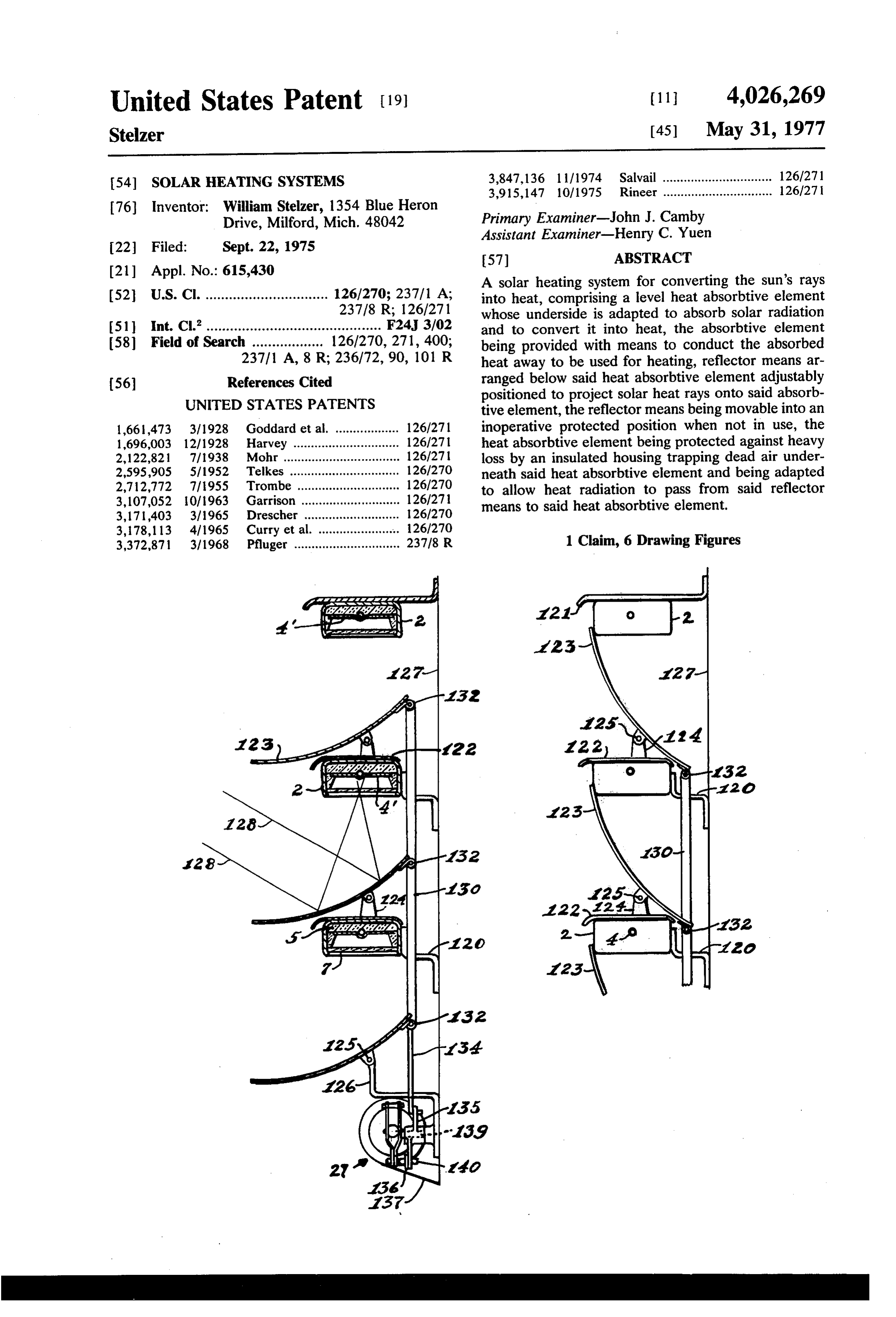
United States Patent (19) 11 4,026,269 Stelzer (45) May 31, 1977 54). SOLAR HEATING SYSTEMS 3,847,136 1 1/1974 Salvail ............................... 126/271 3,915,147 10/1975 Rineer ............................... 126/27 | 76 Inventor: William Stelzer, 1354 Blue Heron
Drive, Milford, Mich. 48042 Primary Examiner-John J. Camby
Assistant Examiner-Henry C. Yuen
(21) Appl. No.: 615,430 A solar heating system for converting the sun's rays 52 U.S. Cl. ............................... 126/270; 237/1 A; into heat, comprising a level heat absorbtive element 237/8 R; 126/271 whose underside is adapted to absorb solar radiation (51 int. C.’............................................ F24, 3/02 and to convert it into heat, the absorbtive element 58) Field of Search .................. 126/270,271, 400; being provided with means to conduct the absorbed 23711 A, 8 R; 236/72, 90, 101 R heat away to be used for heating, reflector means ar 56 References Cited ranged below said heat absorbtive element adjustably
UNITED STATES PATENTS
positioned to project solar heat rays onto said absorb tive element, the reflector means being movable into an 1,66,473 3/1928 Goddard et al. .................. 126/271 inoperative protected position when not in use, the 1,696,003 12/1928 Harvey .............................. 126/27 heat absorbtive element being protected against heavy 2,122,821 7/1938 Mohr ................................. 126/27 loss by an insulated housing trapping dead air under 2,595,905 5/1952 Telkes ............................... 126/27O neath said heat absorbtive element and being adapted 2,712,772 71955 Trombe ............................. 126/270 to allow heat radiation to pass from said reflector 3,107,052 10/1963 Garrison ............................ 126/271 means to said heat absorbtive element. 3,171,403 3/1965 Drescher ........................... 126/270 3, 178,113 4/1965 Curry et al. ... ... 126/270 3,372,871 3/1968 Pfluger .............................. 23718 R 1 Claim, 6 Drawing Figures
Page 2
Drawing sheet — no readable text.
Page 3
Drawing sheet — no readable text.
Page 4
with a desirable coating to obtain maximum absorb
SOLAR HEATING SYSTEMS tivity and minimum emissivity. The tube 4 and plate 4 are insulated against heat loss by an insulating member
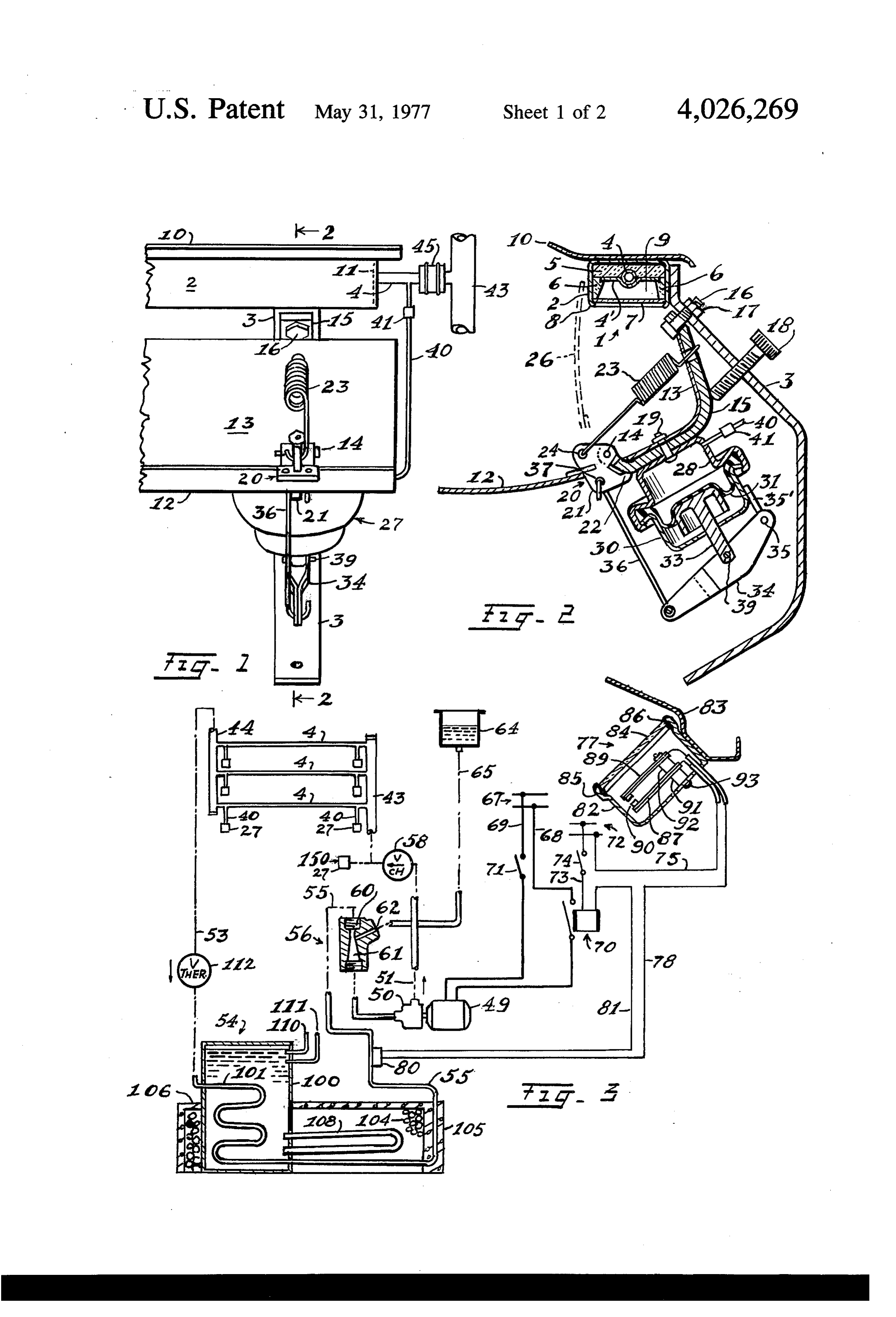
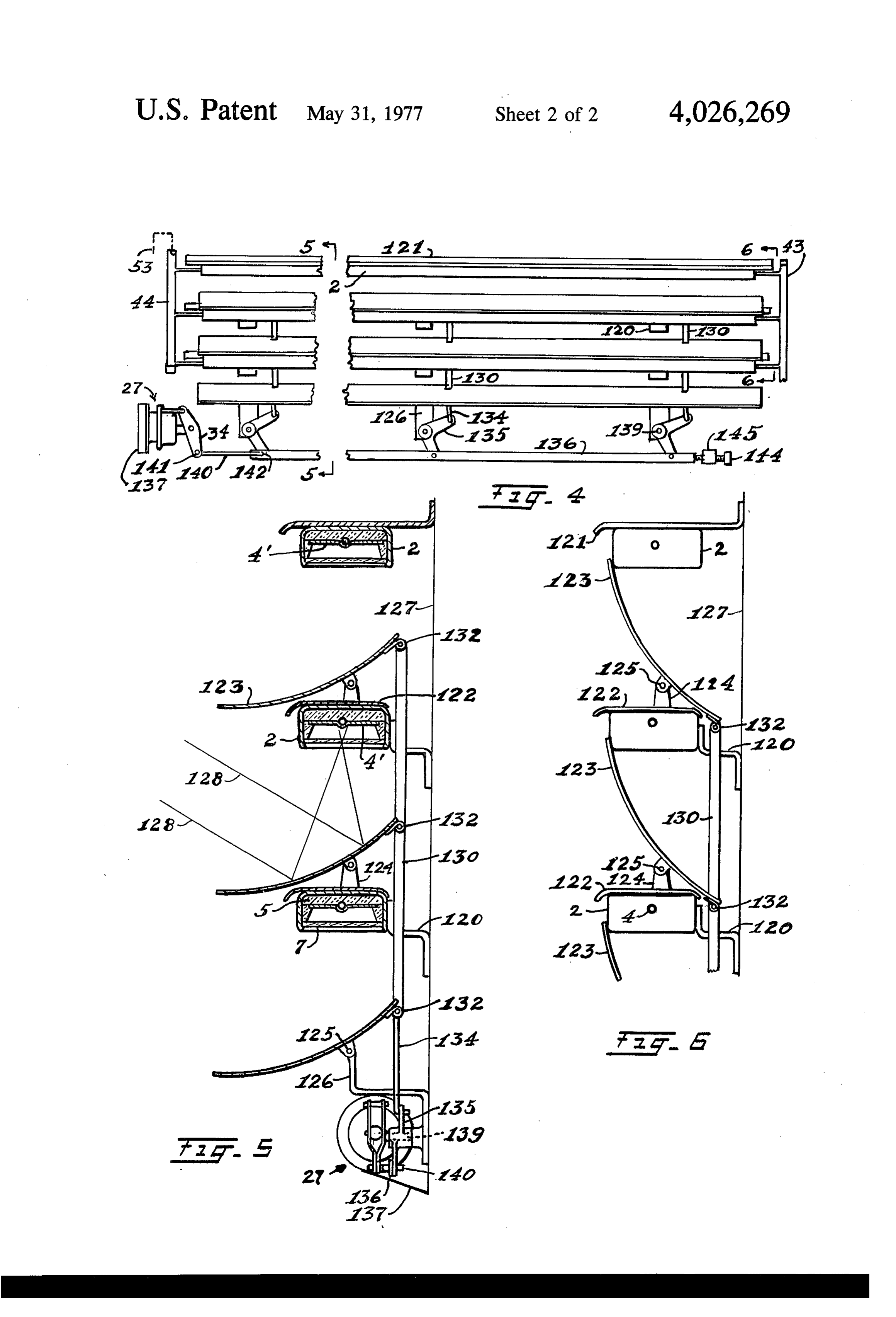
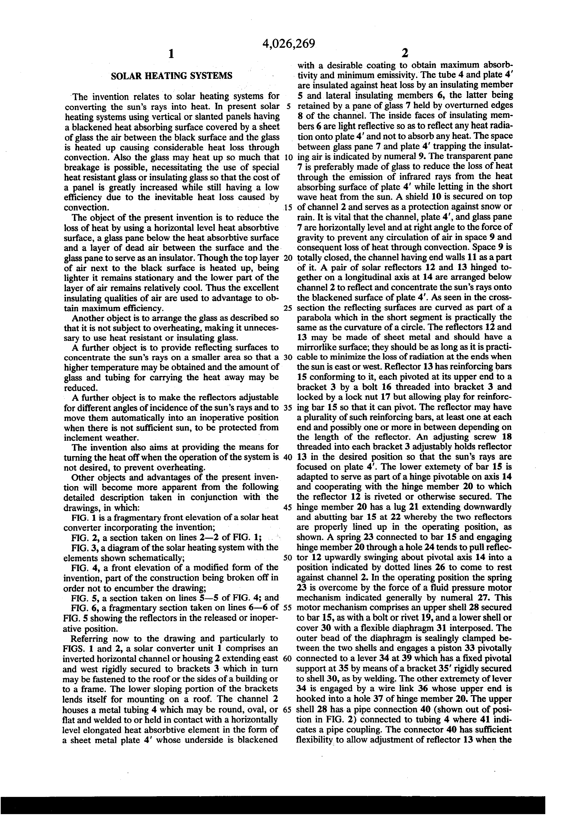
The invention relates to solar heating systems for 5 and lateral insulating members 6, the latter being converting the sun's rays into heat. In present solar retained by a pane of glass 7 held by overturned edges heating systems using vertical or slanted panels having 8 of the channel. The inside faces of insulating mem a blackened heat absorbing surface covered by a sheet bers 6 are light reflective so as to reflect any heat radia of glass the air between the black surface and the glass tion onto plate 4' and not to absorb any heat. The space is heated up causing considerable heat loss through between glass pane 7 and plate 4' trapping the insulat convection. Also the glass may heat up so much that 10 ing air is indicated by numeral 9. The transparent pane breakage is possible, necessitating the use of special 7 is preferably made of glass to reduce the loss of heat heat resistant glass or insulating glass so that the cost of through the emission of infrared rays from the heat a panel is greatly increased while still having a low absorbing surface of plate 4' while letting in the short efficiency due to the inevitable heat loss caused by wave heat from the sun. A shield 10 is secured on top convection. 15 of channel 2 and serves as a protection against snow or The object of the present invention is to reduce the rain. It is vital that the channel, plate 4', and glass pane loss of heat by using a horizontal level heat absorbtive 7 are horizontally level and at right angle to the force of surface, a glass pane below the heat absorbtive surface gravity to prevent any circulation of air in space 9 and and a layer of dead air between the surface and the consequent loss of heat through convection. Space 9 is glass pane to serve as an insulator. Though the top layer 20 totally closed, the channel having end walls 11 as a part of air next to the black surface is heated up, being of it. A pair of solar reflectors 12 and 13 hinged to lighter it remains stationary and the lower part of the gether on a longitudinal axis at 14 are arranged below layer of air remains relatively cool. Thus the excellent channel 2 to reflect and concentrate the sun's rays onto insulating qualities of air are used to advantage to ob the blackened surface of plate 4'. As seen in the cross tain maximum efficiency. 25 section the reflecting surfaces are curved as part of a Another object is to arrange the glass as described so parabola which in the short segment is practically the that it is not subject to overheating, making it unneces same as the curvature of a circle. The reflectors 12 and sary to use heat resistant or insulating glass. 13 may be made of sheet metal and should have a A further object is to provide reflecting surfaces to mirrorlike surface; they should be as long as it is practi concentrate the sun's rays on a smaller area so that a 30 cable to minimize the loss of radiation at the ends when higher temperature may be obtained and the amount of the sun is east or west. Reflector 13 has reinforcing bars glass and tubing for carrying the heat away may be 15 conforming to it, each pivoted at its upper end to a reduced. bracket 3 by a bolt 16 threaded into bracket 3 and A further object is to make the reflectors adjustable locked by a lock nut 17 but allowing play for reinforc for different angles of incidence of the sun's rays and to 35 ing bar 15 so that it can pivot. The reflector may have move them automatically into an inoperative position a plurality of such reinforcing bars, at least one at each when there is not sufficient sun, to be protected from end and possibly one or more in between depending on inclement weather. the length of the reflector. An adjusting screw 18 The invention also aims at providing the means for threaded into each bracket 3 adjustably holds reflector turning the heat off when the operation of the system is 40 13 in the desired position so that the sun's rays are not desired, to prevent overheating. focused on plate 4'. The lower extemety of bar 15 is Other objects and advantages of the present inven adapted to serve as part of a hinge pivotable on axis 14 tion will become more apparent from the following and cooperating with the hinge member 20 to which detailed description taken in conjunction with the the reflector 12 is riveted or otherwise secured. The drawings, in which: 45 hinge member 20 has a lug 21 extending downwardly FIG. 1 is a fragmentary front elevation of a solar heat and abutting bar 15 at 22 whereby the two reflectors converter incorporating the invention; are properly lined up in the operating position, as FIG. 2, a section taken on lines 2-2 of FIG. 1; . shown. A spring 23 connected to bar 15 and engaging FIG.3, a diagram of the solar heating system with the hinge member 20 through a hole 24 tends to pull reflec elements shown schematically; 50 tor 12 upwardly swinging about pivotal axis 14 into a FIG. 4, a front elevation of a modified form of the position indicated by dotted lines 26 to come to rest invention, part of the construction being broken off in against channel 2. In the operating position the spring order not to encumber the drawing; 23 is overcome by the force of a fluid pressure motor FIG. 5, a section taken on lines 5-5 of FIG. 4; and mechanism indicated generally by numeral 27. This FIG. 6, a fragmentary section taken on lines 6-6 of 55 motor mechanism comprises an upper shell 28 secured FIG. 5 showing the reflectors in the released or inoper to bar 15, as with a bolt or rivet 19, and a lower shell or ative position. cover 30 with a flexible diaphragm 31 interposed. The Referring now to the drawing and particularly to outer bead of the diaphragm is sealingly clamped be FIGS. 1 and 2, a solar converter unit 1 comprises an tween the two shells and engages a piston 33 pivotally inverted horizontal channel or housing 2 extending east 60 connected to a lever 34 at 39 which has a fixed pivotal and west rigidly secured to brackets 3 which in turn support at 35 by means of a bracket 35' rigidly secured may be fastened to the roof or the sides of a building or to shell 30, as by welding. The other extremety of lever to a frame. The lower sloping portion of the brackets 34 is engaged by a wire link 36 whose upper end is lends itself for mounting on a roof. The channel 2 hooked into a hole 37 of hinge member 20. The upper houses a metal tubing 4 which may be round, oval, or 65 shell 28 has a pipe connection 40 (shown out of posi flat and welded to or held in contact with a horizontally tion in FIG. 2) connected to tubing 4 where 41 indi level elongated heat absorbtive element in the form of cates a pipe coupling. The connector 40 has sufficient a sheet metal plate 4' whose underside is blackened flexibility to allow adjustment of reflector 13 when the
Page 5
entire reflector and motor mechanism assembly swings lower part of the water tank extends into a gravel bed a short angular distance on bolt 16. It is apparent that 104 contained by an insulated enclosure having sides a number of solar heating units may be used in one 105 and top 106, which may serve as foundations or system, thus the manifolds 43 and 44 serve to connect structural parts of a building. A plurality of large pipes a plurality of solar units in parallel, the connection 108 in the lower part of the gravel bed are connected to between the manifolds and the tubes 4 being facilitated the lower end of tank 100 in such a manner that ther by flexible couplings 45, as shown in FIG. 1. In the mo-syphonic flow of water from the tank heats up the embodiment shown the cross-sectional view in FIG. 2 is gravel bed 104. With this arrangement different zones typical at each bracket 3. of temperature are established, the upper part of tank Referring now to the diagram in FIG. 3, the embodi 10 100 being the hottest and the lower part of tank 100 ment by way of example assumes the use of hydraulic and of the gravel bed 104 having a lower temperature. fluid such as water with anti-freeze solution and rust The hot water in the upper part of tank 100 may be inhibitor for transmitting the heat energy. For this pur circulated in a conventional manner as it is done in pose a centrifugal pump 50 driven by an electric motor present hot water heating systems for heating the build 49 is arranged to pump fluid through pipe 51 to tubes 5 ing as with pipes 110 and 111. It is desirable that enclo 4 via inlet manifold 43 and out through outlet manifold sures 105, 106, and the part of tank 100 extending 44 and pipe 53 to a heat sink 54 for storing thermal above the latter be insulated to have better control of energy from where the fluid is returned through pipe 55 the heat storage and of heating the building for which to the inlet side of pump 50 to complete the closed the system is designed. In order to adjust the rate of circuit. A jet operated pressure amplifier 56 is inter 20 flow through the hydraulic pipes to the time required to posed in line 55. Line 51 has a check valve 58, the valve heat the fluid in tubes 4, I interpose a thermostatic latter being of the residual spring biased type to provide 112 in line 53. This is a conventional valve which enough resistance to prevent a thermosyphon flow is responsive to the temperature of the fluid passing when the system is not in operation. The pressure am through pipe 53 so that with a high temperature the plifier 56 has a narrowing inlet 60 to change pressure 25 valve is wide open to permit maximum flow and with into velocity and a venturi type outlet 61 to change lower temperatures the flow becomes more restricted, velocity back into pressure. A suction inlet passage 62 but it is never entirely closed. It is desirable that the at the narrow portion of the venturi 61 is connected to pipes, including manifolds 43 and 44, between the solar a reservoir 64 by a pipe 65. The electrical circuit for heat collectors and the heat sink be insulated against energizing the electric motor 49 is connected to an 30 heat loss, though the insulation is omitted in the draw electric line 67 where two wires 68 and 69 lead to ling.The modified construction shown in FIGS. 4, 5, and motor 49 with a relay 70 and manual switch 71 inter posed. The relay 70 is energized from a low voltage line 6 is adapted specially for wall mounting and is best 72 where one wire 73 leads to relay 70 with a manual suited for northern climates where the sun is low in the switch 74 interposed, and a second wire 75 leads to a 35 winter and there may be heavy snowfall. The channels solar thermostatic switch 77 which controls the energi housing the heat absorbtive plate are similar to the one zation of relay 70 through wire 78, a thermostatic shown in FIGS. 1 and 2 and thus carry the same numer switch 80 and wire 81. The solar thermostatic switch als. They are mounted one above the other to the south comprises a housing 82 with an attached mounting side of a building or wall by means of brackets 120 and bracket and shield 83 and a glass window 84 secured in 40 121, the latter serving as a shield for the topmost chan a recess 85 of the housing as with sealing compound at nel against rain or snow. The lower channels have 86. Within the housing are two spaced bi-metallic ele shields 122 for the same purpose, particularly when the ments 87 and 89 provided with electric contact points reflectors are in the retracted position as shown in FIG. 90 and secured to the housing with electric insulating 6. The reflectors 123 are pivotally supported by sup spacers 91 and 92 by means of insulated bolts or rivets 45 ports 124 extending upwardly from shields 122 or 93. Wire 75 leads to element 87 and wire 78 to element channels 2 to rotate about pivot pin 125. The lower 89. In both elements the metal having the higher coeffi most reflector is pivoted directly to brackets 126, cient of expansion is on the upper side facing the win which are like brackets 120 secured to the wall, nu dow 84. Both are similar except that element 87 which meral 127 indicating a line marking the outside surface. is closest to the window 84 has a blackened surface so 50 The reflectors have a paraboloid curvature as seen in that the solar rays falling on the blackened surface heat the cross-section so that sun rays are focused onto the up the element 89 while the other element 87 remains heat absorbtive plate 4", lines 128 indicating the pro at ambient temperature because it is shielded from the jection of such rays. The reflectors 123 are connected sun and has no blackened surface. The purpose of this together by connecting links 130 engaging hinge joints arrangement is to make the switch 77 truly responsive 55 132 secured to reflectors 123. The lower ends of links to the solar heat rays and to be independent of the 130 are engaged by push rods 134 at the hinge joints ambient temperature. When the ambient temperature 132 of the reflector so that the reflectors rock in unison increases both elements bend in the same direction when push rods 130 are actuated by a fluid pressure maintaining the gap between the contact points unless motor mechanism 27 working through a number of bell solar radiation with sufficient intensity falls on element 60 cranks link 136. The motor mechanism is mounted to 89 to cause deflection of the latter to close the the face 127 of the building by a bracket 137 and is of contacts. The thermostatic switch 80 is normally the same construction as shown in FIG. 2. The bell closed. It is mounted adjacent pipe 55 and opens only cranks 135 are rotatably supported by studs 139 ex when there is overheating of pipe 55, as for instance tending from brackets 126. One arm of each bell crank when the heat sink is heated up to the maximum de 65 is134. connected to cross link 136 and other to push rods A rod 140 connected to the lower end of lever 34 sired temperature. The heat sink 54 in the example shown comprises a water tank 100 provided with a at 141 also engages one end of the cross link 136 at 142 heating coil 101 connecting line 53 to line 55. The so that all bell cranks, connecting links, and reflectors
Page 6
move in unison when actuated by the motor mecha The operation of the modified construction shown in nism 27. The position of the reflectors may be adjusted FIGS. 4, 5, and 6 is similar to that described, except by an adjusting screw 144 in a threaded bracket 145 that instead of a plurality of fluid pressure motor mech secured to the wall of the building, acting as a stop for anisms 27 only a single unit is used and linkage is sup rod 136. The reflectors are urged into the inoperative 5 plied so that all reflectors are forced to move together. protected position shown in FIG. 6 by the weight of Thus the diagram shown in FIG. 3 also applies to the links 130 which may be made heavy enough to supply modified construction shown in FIGS. 4, 5, and 6 with the necessary force after the fluid pressure motor the exception that instead of the plurality of motor mechanisms 27 there is only a single motor mechanism mechanism is deemergized.
The operation of the sytem is intermittent. When the 10 indicated by numeral 150. In FIG. 4 this single motor sun is not shining the solar converter is in a closed mechanism is shown in the energized position where position where reflector 12 of the construction shown the reflectors 123 are in a position to reflect the sun's rays when they are at the lowest angle as illustrated in in FIGS. 1 and 2 is tilted upwardly as indicated by FIG.
dotted lines 26 so that the mirror surfaces are protected hours5.in The angle varies to some degree during the which the solar heating system is in operation;
from the weather. Motor 49 is at rest and no fluid is 5 being circulated. Assuming now the sun is shining on 4' however, due to the width of the heat absorbtive plate solar thermostatic switch 77, the sun's rays heat up the ated. and window 7 considerable variation can be toler black surface of bi-metallic member 89, causing ment in If it is desired to narrow the heat absorbtive ele contacts 90 to close, and assuming that the manual relation to the width of the reflectors 123, the structure shown in FIGS. 4 and 5 lends itself readily to switch 74 is closed, the control circuit energizing relay 20 the 70 is closed, which in turn closes the electric power application of a solar tracking mechanism because circuit to start motor 49 and pump 50. The latter of the single actuating mechanism and single adjusting pumps water through the closed pipe circuit and gener device to which the tracking mechanism can be ap ates a certain hydraulic pressure which is also transmit plied. Such tracking mechanisms are known to the art ted to motor mechanisms 27 through the small tubings 25 and it would serve no purpose to include such detail in 40 acting on diaphragms 31 as shown in FIG. 2. Piston the present disclosure. While three reflectors 123 and 33 is pushed downwardly to swing lever 34 about pivot heat absorbers are shown in FIGS. 4 and 5, it is appar 35 to actuate hinge member 20 through connecting entThe that any number or only a single unit could be used. embodiments shown are calculated to fulfill the link 36 to pull reflector 12 downwardly, swinging about pivot 14 into the position shown where the sun's rays 30 objects above stated, but it will be appreciated that the are received and projected onto the heat absorbtive invention is susceptible to modification, variation and plate 4'. The latter heats up and transmit the heat to the change without departing from the scope or fair mean water in the tube 4. The position of the reflectors may ingI claim:
of the invention.
be manually adjusted with screw 18. The width of the heat absorbtive plate 4' permits the focus to be off to 35 tion1. Ainto solar heating system for converting solar radia heat, comprising an elongated horizontally some extent, so that an adjustment needs be made only disposed level heat absorbtive element extending east a few times per year. At the start of the operation, when and west having a horizontally level underside at right the heat transfer fluid is still cold, valve 112 has the angle to the force of gravity, said underside being maximum restriction so that the flow of fluid is very 40 adapted slow and the hydraulic pressure in pipes 51 and 53 is for good solar radiation absorbitvity, a hori high, thus furnishing ample power for the movement of zontally level transparent pane underneath said heat the motor mechanism 27 as described. After the fluid absorbtive element, a space between said underside heats up passing slowly through tubes 4 the thermo and said pane to contain a level layer of dead air, an insulating housing to cover said heat absorbtive ele static valve 112 opens up more and allows a faster flow 45 ment and having side walls supporting said transparent as long as the water passing through it has a sufficient pane and confining said layer of dead air, reflector temperature. The faster flow reduces the heat gener ated by pump 50 but the jet action past inlet 62 of the means having a reflective surface below said heat ab pressure amplifier draws fluid from reservoir 64 and sorbtive element and said pane arranged at such angle thereby boosts the hydraulic pressure in the entire as to receive solar radiation and to reflect it through closed circuit providing sufficient pressure above atmo 50 said pane to said underside of said heat absorbtive spheric pressures for the expansible motor mechanism element to convert said radiation into heat, said reflec 27 to hold reflector 12 in the operating position. It tor means (and) being movable and adjustable by ad should be noted that the boost in pressure does not justing means to focus the solar radiation reflected by make more work for pump 50. When the solar radia said reflector means onto said horizontally disposed tion drops below a certain predetermined intensity, the 55 heat absortive element when in the operative position, bi-metal element 89 moves out of contact to break the (and) means to controllably render said reflector control circuit, whereby motor 49, and pump 50 are means ineffective by tilting said reflector means stopped and the head of the pump is reduced to zero. towards said housing so that said reflecture surface and Residual pressure above atmospheric is relieved said heat absorbtive element are not exposed to the sun through passage 62 and reservoir 64. Relieving the 60 and are shielded from adverse weather by said housing, hydraulic pressure in the motor mechanism 27 allows and means to conduct the heat absorbed by said ele ment away to be used.
reflector 12 to be returned to the inoperative folded ak k 2k xk sk position by force of springs 23.
Provenance
- Collection
- Cited prior art
- Original PDF
- patentimages.storage.googleapis.com →
- Filed
- 1975-09-22
- Pages
- 6
- Method
- pdftotext (the PDF's own text layer) + pdftoppm 300dpi page scans
- Source
- Google Patents bibliographic record
- Granted
- 1977-05-31
- Inventors
- William Stelzer
- Transcribed from
- patentimages.storage.googleapis.com →