patent · US4193755
Liquid to gas fuel conversion burner device
18 March 1980
Page 1 — bibliographic record
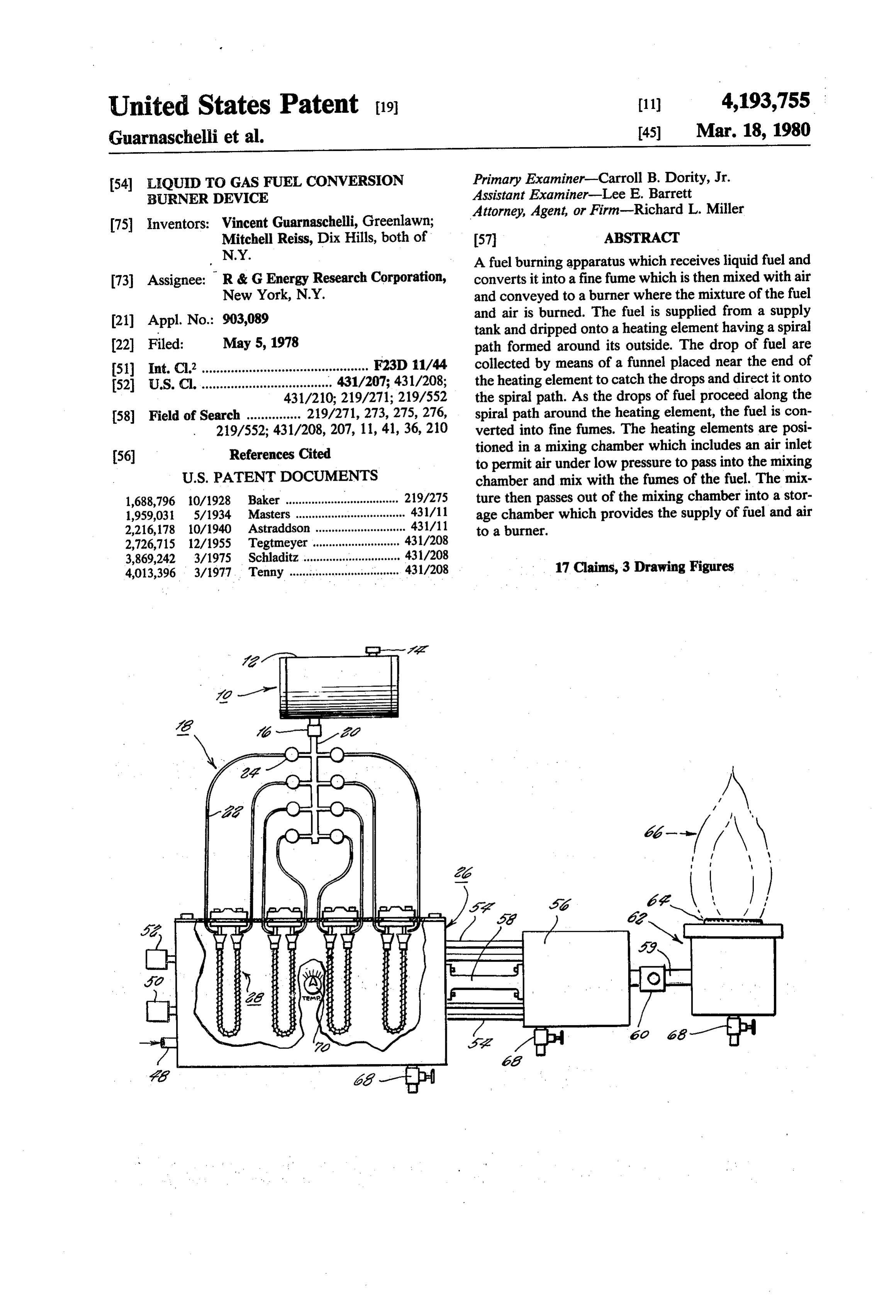
United States Patent (19) 11) 4,193,755 Guarnaschelli et al. 45) Mar. 18, 1980 (54) LIQUID TO GAS FUEL CONVERSION Primary Examiner-Carroll B. Dority, Jr. BURNER DEVICE Assistant Examiner-Lee E. Barrett Attorney, Agent, or Firm-Richard L. Miller 75 Inventors: Vincent Guarnaschelli, Greenlawn;
Mitchell Reiss, Dix Hills, both of 57 ABSTRACT
N.Y. A fuel burning apparatus which receives liquid fuel and 73) Assignee: R & G Energy Research Corporation, converts it into a fine fume which is then mixed with air New York, N.Y. and conveyed to a burner where the mixture of the fuel (21) Appl. No.: 903,089 and air is burned. The fuel is supplied from a supply tank and dripped onto a heating element having a spiral (22 Filed: May 5, 1978 path formed around its outside. The drop of fuel are 51) Int. Cl’.............................................. F23D 11/44 collected by means of a funnel placed near the end of 52 U.S. C. .................................... 431/207; 431/208; the heating element to catch the drops and direct it onto 431/210; 219/271; 219/552 the spiral path. As the drops of fuel proceed along the 58 Field of Search ............... 219/271, 273, 275,276, spiral path around the heating element, the fuel is con 219/552; 431/208, 207, 11, 41, 36,210 verted into fine fumes. The heating elements are posi (56. References Cited tioned in a mixing chamber which includes an air inlet to permit air under low pressure to pass into the mixing
1,688,796 10/1928 Baker .................. ... 219/275 ture then passes out of the mixing chamber into a stor 1,959,031 5/1934 Masters ..... ... 431/11 age chamber which provides the supply of fuel and air 2,216,178 10/1940 Astraddson ... 431/11 to a burner.
2,726,715 12/1955 Tegtmeyer ..... ... 431/208 3,869,242 3/1975 Schladitz .............................. 431/208 4,013,396 3/1977 Tenny ........................ 431/208 17 Claims, 3 Drawing Figures
Page 2
Drawing sheet — no readable text.
Page 3
Drawing sheet — no readable text.
Page 4
burner which can often create a dangerous system.
LIQUID TO GAS FUEL CONVERSION BURNER whereby an inefficient amount of fuel and air mixture is
provided. Also, when a sufficient number of the holes
BACKGROUND OF THE INVENTION 5 are clogged and are not properly maintained, explosions could also frequently occur in the furnace or fuel burn
This invention relates to fuel burning devices and ing equipment.
more particularly to a method and apparatus for con SUMMARY OF THE INVENTION verting liquid fuel to gas fuel and utilizing the gas fuel for a burner.
Fuel burning equipment are well known and are of to Accordingly, it is an object of the present invention provide a method and apparatus for burning fuel, and d numerous different types. Essentially, the type of equip especially liquid fuel, which avoids the aforementioned ment will depend on the fuel being utilized. Some equip problems of prior art devices.
ment are designed to receive solid fuel such as coal A further object of the present invention is to provide while others are able to utilize gas fuel. One of the most 15 a fuel burning apparatus which completely converts the popular types of fuel burning equipment are those liquid fuel into fine fumes which can then be mixed with which utilize liquid fuel as either oil, kerosene, gasoline, air and conveyed to a burner for a more efficient fuel or standard heating number 2 fuel. .
The fuel burning equipment, especially of the liquid burning apparatus.
fuel type are utilized for numerous purposes. For exam provide afurther
Still a object of the present invention is to fuel burning apparatus including a specially ple they can be in the form of an oil furnace for use in 20 designed heating device for converting the liquid fuel home heating equipment. Additionally, such liquid fuel burning equipment is also utilized as part of hot water into its gas fumes for subsequent mixing with air to heaters, stoves, industrial boilers, and even the internal provide a mixture for a fuel burner. Yet a further object of the present invention is to combustion engine can be considered as such as liquid fuel burning system. 25 provide a spiral heating element for use in converting Most of the conventional liquid fuel burning devices liquid fuel to its gas fumes for use in a fuel burning take the liquid fuel, such as oil, and atomize the oil into apparatus.
small drops by means of pressure. The air pressure can Still a further object of the present invention is to be supplied by a motor driven fan or a rotary burner provide a fuel burning apparatus including a specially type. In such cases, the atomized liquid fuel mixed with 30 designed mixing chamber where liquid fuel can be al the air is sent to a burner where the heat and flame is most entirely converted into its gas vapor and mixed produced. Other types of oil burners send the oil di with air to provide an improved fuel mixture for use in rectly into the furnace chamber. The oil is permitted to a burner.
give off some of its vapor and this vapor flows up A further object of the present invention is to provide wardly in the furnace toward the burner which is posi-35 a fuel burning apparatus which is more efficient, sub tioned at the top. As it moves upward, it combines with stantially odorless, substantially without any soot, and air and this combination is then burned. more effective then conventional fuel burning appara One of the main problems with existing types of fuel tuS.
burning equipment concerns the efficiency of operation. Yet another object of the present invention is to pro Part of the reduced efficiency occurs in the lack of 40 vide a method of burning fuel by heating liquid fuel to utilization of all of the fuel. There is much fuel waste in convert it almost entirely into fumes which can be all types of existing equipment since not all of the fuel is mixed with atomized or vaporized and accordingly many liquid apparatus. air to provide an improved fuel burningparticles remain. Some of these liquid particles are not Yet a further object of the present invention is to utilized at all and accordingly reduces the amount of 45 provide a fuel burning apparatus comprising a unique output heat from a given supply of fuel. An additional heating element which can accept fuel of a liquid type, loss of efficiency results in the fact that much of the fuel remains in its liquid form in larger particles and cannot convert it into fine fumes which are mixed with air to burn during the given amount of time for the burning become a combustible mixture which is supplied to a cycle. As a result, these particles are never sufficiently 50 burner to produce a high efficient burning device. Briefly, the invention comprises a fuel burning appa converted into heat and provide another source of heat loss. ratus which includes a heating device for receiving a In addition to actual heat loss and lack of efficiency of liquid fuel and converting it almost entirely into fine existing equipment, the conventional type of burners, fumes. The fumes, or vapor, are mixed with air to pro and especially oil burning equipment, produce a tre 55 vide a combustible mixture. A conveying device trans mendous amount of pollutants. Much of the liquid fuel ports the mixture to a burner where the combustible particles are converted into soot and other waste prod mixture is burned.
ucts which pollute the atmosphere as well as providing In an embodiment of the invention, the heating de dirt in the environment around the fuel burning equip vice includes at least one heating element having a spi ment. Also, the lack of complete burning produces 60 ral path around the outside thereof. A receiver is con smoke and other odors in the environment also tending nected to the heating element in order to receive all of the pollute the atmosphere. the liquid fuel and direct it onto the spiral path. In this Other problems also exist in connection with the manner, the liquid fuel flows around the heating ele present type of fuel burning equipment, and especially ment until it is almost entirely converted into the fine the oil burners. Because the liquid fuel is either atom 65 fumes. The heating elements are positioned in a mixing ized or the vapors form naturally from the fuel, there tank having an air inlet and an outlet. Air under low still exists large particles of liquid fuel throughout the pressure is sent into the mixing tank and traverses the burner. These tend to clog the holes in the conventional heating element to mix with the fumes. The mixture
Page 5
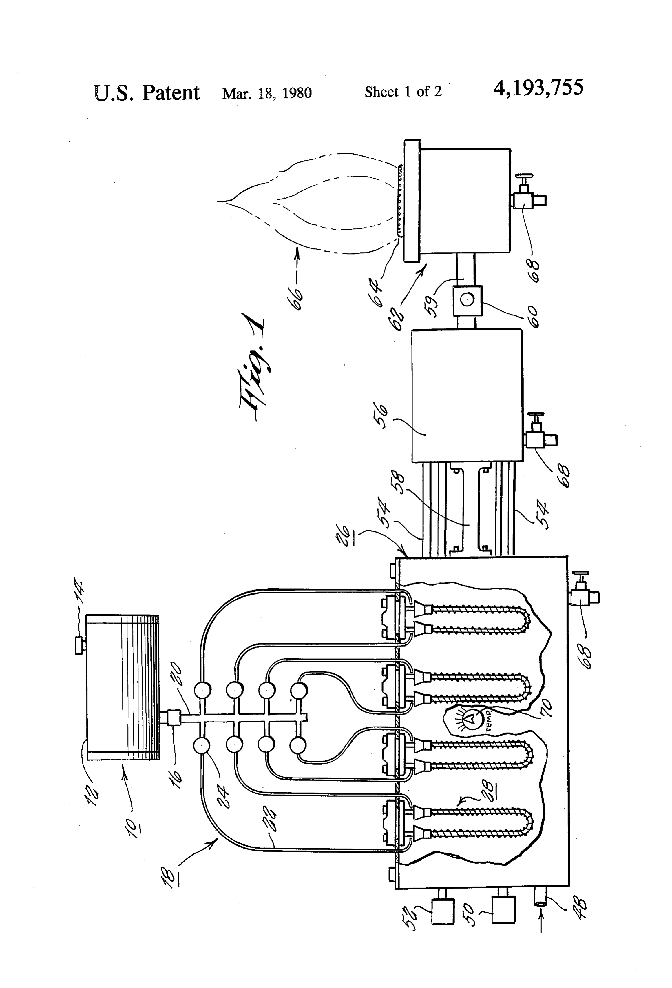
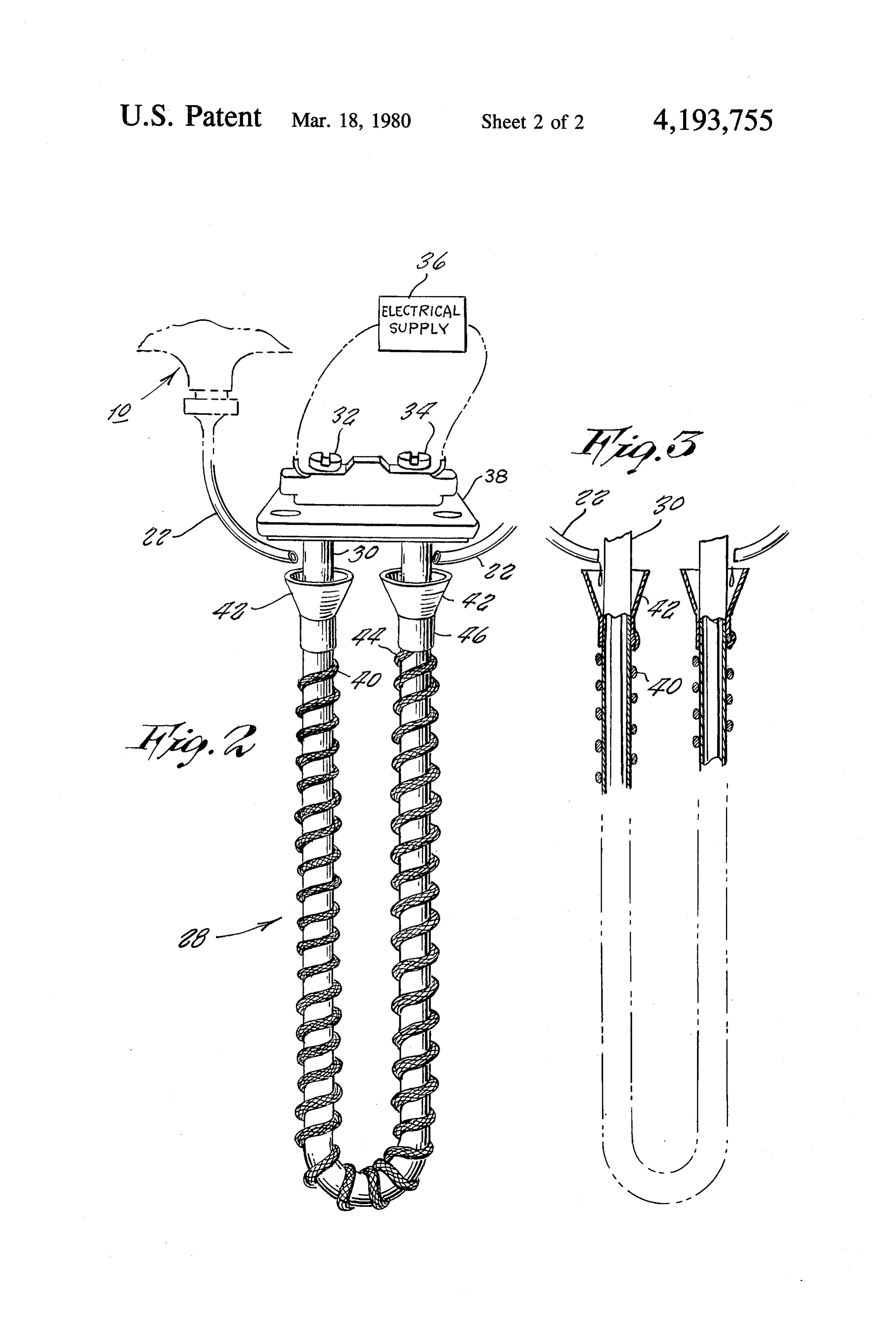
then leaves through the outlet means and through a 34 which are in turn connected to a source of electrical conveying device to the burner. supply 36. The heating element 30 is mounted onto a The invention also contemplates a method of burning head support 38 which permits it to be easily installed fuel including the steps of heating the liquid fuel in and held in place in the mixing tank. One such typical order to convert it almost entirely into fine fumes or heating element is available under the name CALROD, vapor. The fine fumes are mixed with the air and sup produced by the General Electric Company. plied to the burning device. Around the outside of the heating element is wound a In an embodiment of the invention, the heating is spiral retaining path 40 which can be formed of a mate achieved by applying the fuel in individual drops onto a rial which will retain the liquid. By way of example, it heating element and directing the fuel along the outer 10 can be formed of stranded wire, such as picture frame surface of the heating element until it is almost entirely wire, or other similar material. Adjacent the ends of the converted to the fine fumes. Air is then passed across legs of the U-shaped heating element are placed funnels the heating element to provide the combustible mixture 42. The ends of the stranded wire 40 shown at 44 are which is then supplied to the burner. inserted between the lower portion 46 of the funnel and The invention also contemplates a unique heating 15 the heating element 30.
element having a spiral path therearound. The heating The ends of the capillary tubes 22 are positioned element is of the electrical kind whereby the ends can be adjacent the openings of the funnels 42. The other ends connected to an electrical power supply. The spiral can of the tubes 22 ultimately reach to the fuel supply tank be formed of stiff absorbing material, such as stranded 10. The liquid fuel is controlled so that it will provide wire which is wound around the outside of the heating 20 the fuel at a drop rate. The drops are collected by the element. A funnel is positioned at the ends of the heat funnels 42 to prevent any of the fuel from escaping and ing element to collect the liquid fuel which is dripped being wasted. The funnels then direct the fuel into the into the funnel and then sent through the stranded wire stranded wire which retains the fuel and directs it in a around the heating element until it is almost entirely spiral path around the heating rod. As the fuel proceeds converted into fine fumes. 25 along the spiral path, it is heated by the heating rods so The aforementioned objects, features and advantages that it turns into fine fumes or a type of vapor fuel. of the invention will, in part, be pointed out with partic Referring back to FIG. 1, it will be seen that the ularity, and will, in part, become obvious from the fol mixing tank 26 includes an air inlet 48 where air can be lowing more detailed description of the invention taken applied at a low pressure. The pressure valves 50 and 52 in conjunction with the accompanying drawings, which 30 provide the appropriate control of the pressure and also form an integral part thereof. emergency pressure release, as needed. The air entering BRIEF DESCRIPTION OF THE DRAWINGs into the mixing tank is permitted to pass across the heating elements 28 and to mix with the fumes of the
In the drawings: fuel. This mixture of air and fuel vapor passes across the FIG. 1 is a schematic drawing of the fuel burning 35 mixing tank and leaves through the connecting tubes 54 apparatus of the present invention and wherein the provided in parallel at the output of the mixing tank 26. mixing tank is shown partly cut away; The mixture passes into a storage tank 56. The storage FIG. 2 is an isometric drawing of one of the heating tank 56 is shown interconnected by means of a brace 58 elements utilized in the apparatus shown in FIG. 1, and to the main mixing tank 26. At the outlet of the storage FIG. 3 is a sectional view through a portion of the tank 56 is connected a supply tube 59 with a control heating elements showing the operation thereof. valve 60 in series therewith. The mixture of air and fuel In the various figures of the drawings like reference fumes passes through the tube 59 to a conventional characters designate like parts. burner 62 including a burning element 64 therein. The
DESCRIPTION OF THE PREFERRED
fuel is then permitted to burn as shown at 66. Appropri 45 ate drain elements 68 are provided at the bottoms of
EMBOOMENTS each of the tanks as well as the burner as is well known Referring now to FIG. 1, the fuel burning apparatus in the art.
of the present invention is shown to include a fuel sup The operation of the fuel burning system will now be ply shown generally at 10 and including a fuel tank 12 explained. The liquid fuel is provided either by a gravity with an inlet nozzle 14 and an outlet control. 16. The feed or pressure feed, or the like, through the tubes tank is typically a gravity feed tank whereby the fuel which enter into the supply tank which is otherwise will automatically flow down through a valve control sealed. The liquid fuel is sent directly to the tops of the system shown generally at 18. The control system in heating spiral elements. The needle valves in the tubing cludes a main flow tube 20 with a plurality of individual are controlled so that the liquid is applied onto heating capillary feed tubes 22 flowing from the main tube 20. 55 elements in a drop like fashion.
In each of the capillary tubes is provided a needle valve The electrical heating elements are connected to a 24, or other similar type of valve, which is capable of heat supply and the appropriate temperature set by regulating the flow of liquid fuelso as to reduce its flow means of the control 70, as is well known in the art. The down to a drip rate. fuel is collected by the funnels and is directed around The liquid fuel is provided into a mixing tank shown 60 the spiral path to thereby allow enough time to convert generally at 26 which can be formed of steel, or other the oil into fine fumes and develop the fumes. These such similar material. Positioned in the mixing tank 26 fumes are then mixed with air to produce the appropri are a plurality of heating devices shown generally at 28. ate combustible mixture so that a mere spark can cause Each of the heating devices are connected in parallel. the mixture to burn with the greatest efficiency produc Referring now to FIGS. 2 and 3, the heating devices 65 ing a tremendous economy with little pollution. The will be shown in more detail. The heating devices 28 mixing tank permits the air to enter at a low pressure. each include a U-shaped electrical heating element 30 This can be provided by means of an air blower, or the having the ends connected to electrical terminals 32 and like, as is well known. The air passes across the heating
Page 6
elements and leaves through a number of outlet holes theoretically produce 140,000 BTU. However, this is connected with tubing, such as copper tubing. The air only in theory. With the 30-40% efficiency, the home pressure can be approximately one pound or there unit can only realize 42,000-56,000 BTU from one gal about. lon of such fuel oil. The reason for such low efficiency The mixture passes through the storage tank and into 5 is that the stack temperature is approximately 600' the burner. The burner head can consist of a series of F-700' F. Therefore, a large percentage of the heat holes of 40,000 drill size or the like, placed in a circle or goes up the chimney as waste product. other similar shape. When the fumes mixed with air pass The most efficient type of conventional oil burner is through these holes it causes a little separation which the Custom Mark III Oil Unit, produced by the Axel allows more air inbetween and creates an ideal condi 10 Anderson Company, Williamsport, Penna. This is ap tion for burning the fumes. proximately 60% efficient since it utilizes redirection of It has been discovered that with the present appara the fuel and reburning of the fuel product. As a result, tus, there is achieved a tremendous improved efficiency the stack temperature is reduced to about 350 F.-400' over conventional prior art types of equipment. For F. As a result, from one gallon of number 2 fuel oil, example, one gallon of fuel has been found to provide as 15 approximately 84,000 BTUs can be obtained. much heat as six times as much when utilizing conven The present invention has been found to produce a tional equipment. Furthermore, because of the design of stack temperature of about only 10 F. above the ambi the present equipment, substantially every drop of oil ent temperature. It will be noted that this is extremely fed into the equipment is utilized so that there is almost low in comparison to conventional burners. As a result, no loss of fuel in the system. For example, the use of the 20 the efficiency produced is better than 99%. funnel makes sure that all of the fuel is directed into the As is evident from the foregoing description, one of spiral and also prevents the air from blowing the oil the reasons for this efficiency is that substantially all of drops away from the spiral element. the fuel is evaporated and converted into a vapor like When fed in the drop like manner, the forces that product which is mixed with the air to produce the hold the molecular structure of the fuel as a liquid can 25 combustible material. Accordingly, there is little waste change as a result of the spiral flow around the heating of fuel. Furthermore, because the fuel is all converted element. This permits the fuel to become a very fine into the vapor like material, there are no particles which vapor. With this process, the natural state of the fuel is can escape to produce waste. Furthermore, in most not destroyed. However, it is converted into a vapor prior art systems, the air is supplied by means of force like fume which permits it to combine easily with the 30 feeding utilizing a blower or high pressure air input. air. As a result, it burns more efficient and extremely This high pressure tends to send alot of the heat up the clean. For example, it has been found that the resultant stack producing great amount of wasted energy. Be flame is odorless and does not produce any soot. cause the present system utilizes extremely low pressure The present apparatus has been in operation for a air, there is no force for pushing the fuel and air mixture period of time and it has been found that the walls 35 into the stack as waste product. .
around the apparatus are almost entirely sootless. Also, An additional reason for the efficiency is that the fuel a shiny aluminum plate or the like inserted into the is evaporated at a controlled temperature. In the prior flame has been found to produce no soot on the plate. systems the fuel is left to evaporate at either normal or Other similar tests have been carried out to note that the very low temperatures whereby much of the fuel will result is almost no pollution while producing the ef. remain in its liquid state with very little vapor being ficienct output. produced. On the other hand, some systems will rely on Although the heating element has been described by the walls of the burner itself to produce the evaporation means of wrapping around the heating element, the and when these get too hot the entire molecular struc heating device can be manufactured as a unitary ele ture of the fuel is broken down and byproducts are ment with the spiral effect already included around the 45 produced which result in great waste. By means of the device itself. This would produce a unique type of spiral unique heating elements of the present invention, appro heating element which would direct all of the fuel priate control of the heating temperature is obtained around the heating element providing sufficient time for whereby all of the fuel is converted into vapor while at it to become transformed into its vapor like state. How the same time the fuel does not break down but rather ever, it is believed that in addition to the spiral arrange 50 remains as fuel but only the bonds holding together the ment, similar types of arrangements could also be in molecular structure as a liquid are separated to produce cluded whereby sufficient time is provided so that all of the very fine vapor, the liquid fuel will be retained around the surface of a There has been disclosed heretofore the best embodi heating element giving it enough time and opportunity ments of the invention presently contemplated. How to be converted from its liquid state into the vapor like 55 ever it is to be understood that various changes and 'fume state needed to combine with the air. modifications may be made thereto without departing By way of example, the invention has been tried with from the spirit of the invention.
various types of heating fuel. It has been found that We claim:
efficient operation is achieved when utilizing a heating 1. A fuel burning apparatus comprising: number 2 fuel as well as oils or kerosene. Used engine receiving means for receiving a liquid fuel and dis oil when strained produces efficient results. pensing it a drop at a time; In order to compare the extremely efficient and soot heating means comprising at least one heating ele less operation, various types of oil burners have been ment and stranded wire spirally wound about the compared. Utilizing a standard type of oil burner as is heating element, the stranded wire receiving the used in a home, it has been found that only 30%-40% of 65 drops of liquid fuel from the receiving means and efficiency is obtained. Thus, in utilizing fuel, only a directing the drops of liquid fuel through the wire portion of the total available energy can be achieved. It and around the heating element for converting the has been found that one gallon of number 2 fuel oil can liquid fuel into fine fumes;
Page 7
mixing means comprising a mixing tank having an air mixing the fine fumes with air by passing air at a low inlet means and outlet means, said heating element pressure across the heating element; and being positioned in said mixing tank such that air supplying the mixture of air and fine fumes to a burn from said air inlet means can traverse said heating ing device to form the mixture.
element to mix with the fumes, said mixture leaving 5 10. A method as in claim 9 and wherein said heating through said outlet means; element is contained in a chamber, and wherein said burner means for burning the mixture of air and fine steps of mixing comprises the steps of blowing air fumes, and through said chamber so that it crosses the heating conveying means for supplying said mixture from 10 element and can mix with the fumes.
said mixing means to said burner means. 11. A method as in claim 9 and further comprising the 2. A fuel burning apparatus as in claim 1 and wherein step of controlling the temperature of the heating ele said heating element is a U-shaped electrical heating ment to thereby regulate the rate of conversion into fine element having the ends thereof capable of connection fumes.12. A method as in claim 9 and further comprising the to an electrical power supply, and wherein said receiv 15 steps of placing a funnel about the leg of the heating ing means comprises funnels adjacent the ends of the element adjacent its ends to catch the fuel applied legs of the U-shaped heating element, the ends of the thereon, and to direct it into the spiral path around the stranded wire being respectively held between said heating element.
funnels and said heating element. 13. A method as in claim 12 and wherein said step of 3. A fuel burning apparatus as in claim 1 and wherein forming the spiral path comprises the step of wrapping there are a plurality of said heating elements connected a stranded wire about a U-shaped heating element, posi in said mixing tank in parallel relationship with each tioning a funnel at the end of each leg, and locating the other.
4. A fuel burning apparatus as in claim 1 and wherein ends of the wire between the funnel and the heating said mixing means further comprises a gravity feed 25 element. 14. A method as in claim 9 and wherein said step of system for supplying liquid fuel to the receiving means. applying the fuel uses a gravity feed supply. 5. A fuel burning apparatus as in claim 4 and further 15. A spiral heating element for use as a heating de comprising control valve means interconnected be vice for converting liquid fuel into fine fumes for use in tween said gravity feed means and said mixing means a fuel burning apparatus, said spiral heating element for regulating the supply of liquid fuel to the drip rate. 30 comprising:
6. A fuel burning apparatus as in claim 1 and wherein a heating element having a spiral path of stranded said conveying means comprises a storage tank, a plu wire therearound, and receiving means coupled to rality of conveying tubes interconnecting said outlet said element for receiving the liquid fuel and di means with said storage tank, and a supply tube inter recting it into said spiral path, whereby the liquid connecting said storage tank with said burner means. 35 fuel flows through the stranded wire around said 7. A fuel burning apparatus as in claim 1 and further heating element until it is converted almost entirely comprising pressure control means for supplying the air into fine fumes.
at said air inlet means at a low pressure. 16. A spiral heating element as in claim 15 and 8. A fuel burning apparatus as in claim 2 and further wherein said heating element is a U-shaped electrical comprising temperature control means for controlling heating element having the ends thereof capable of the heating of said electrical heating elements. connection to an electrical power supply, and wherein 9. A method of burning fuel comprising: said receiving means comprises funnels adjacent the forming a spiral path of stranded wire about a heating ends of the legs of the U-shaped heating element, the element; ends of the stranded wire being respectively held be supplying a liquid fuel at a drop rate on the stranded 45 tween said funnels and said heating element. wire; 17. A spiral heating element as in claim 15 and heating the heating element as the drops of fuel pass wherein said spiral path is integrally formed in a single through the stranded wire about the heating ele unit with said heating element. s ment to convert it into fine fumes;
Provenance
- Collection
- Cited prior art
- Original PDF
- patentimages.storage.googleapis.com →
- Filed
- 1978-05-05
- Pages
- 7
- Method
- pdftotext (the PDF's own text layer) + pdftoppm 300dpi page scans
- Source
- Google Patents bibliographic record
- Granted
- 1980-03-18
- Inventors
- Vincent Guarnaschelli; Mitchell Reiss; R AND G ENERGY RES CORP
- Transcribed from
- patentimages.storage.googleapis.com →